1
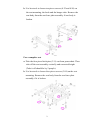
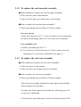
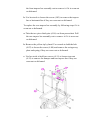
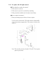
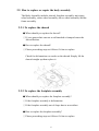
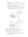
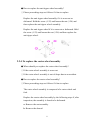
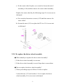
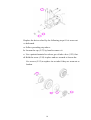
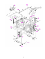
Merits
P710/P720 series
Service Manual
Nov.1.2006 V1
Index
1. Introduction ............................................................................1
2. Service guide ...........................................................................1
2.1.
2.2.
How to replace or repair the seat assembly ................................................ 1
2.1.1.
To replace the seat body ................................................................................... 1
2.1.2.
To replace the seat base plate assembly ............................................................ 3
2.1.3.
To replace the seat tower assembly ................................................................... 3
2.1.4.
To replace the left/right armrest ........................................................................ 5
How to replace or repair the body assembly .............................................. 6
2.2.1.
To replace the shroud ....................................................................................... 6
2.2.2.
To replace the footplate assembly ..................................................................... 6
2.2.3.
To replace the anti-tipper wheel assembly ........................................................ 7
2.2.4.
To replace the caster wheel assembly................................................................ 8
2.2.5.
To replace the driver wheel assembly ............................................................... 9
2.2.6.
To replace the frame assembly........................................................................ 11
The numbers shown in this service manual is just for reference. The part
numbers should be in accordance with current exploded drawing.
1. Introduction
The purpose of this manual is to provide dealers and/or distributors with
the product information and instructions that are required for servicing the
P710/P720 powerchair.
2. Service guide
The P710/P720 powerchair consists of three main parts:
n Seat assembly
n Body assembly
n Electrical system (Please refer to P7 series Shark or VR2 service
manual)
2.1. How to replace or repair the seat assembly
The Seat assembly includes the seat body, the seat tower assembly, the
seat base plate assembly and the left/right armrest.
2.1.1. To replace the seat body
◆ When should you replace the seat body?
◇ If the seat body is worn out.
◇ If the seat body is pierced or scratched by something.
◇ If the powerchair crashed cause the seat body out of shape.
◆ How to replace the seat body?
◇ Please proceeding steps as follows if it has to replace.
Replace the seat body by the following steps if it is broken.
For eazy on seat
a. Push the seat swing away plate with yellow tip (4.06 with 4.09)
under the seat down to unlock it. Lift the rear part lightly and
move back of seat from powerchair. Take off the seat assembly
vertically. (See page 4)
1
b. Use hex tools to loosen ten pieces screws (4.23 and 4.26) on
the seat mounting, the hook and the hanger tube. Remove the
seat body from the seat base plate assembly if seat body is
broken.
For a complete seat
a. Take the four piece hitch pins (3.11) out from powerchair. Then
take off the seat assembly vertically and concerted height
(Take it off should be by 2 people).
b. Use hex tools to loosen four pieces screws (3.09) on the seat
mounting. Remove the seat body from the seat base plate
assembly if it is broken.
2
2.1.2. To replace the seat base plate assembly
◆ When should you replace the seat base plate assembly?
◇ If the seat base plate is deformation.
◇ If the seat base plate out of shape due to an accident.
◆ How to replace the seat base plate assembly?
◇ Please proceeding steps as follows if it has to replace.
For eazy on seat
Follow preceding step of 2.1.1. You can remove the seat mounting,
the hook and the hanger tube too if it is worn out or deformed.
For a complete seat
a. Follow preceding step of 2.1.1.
b. Use hex tools to loosen two screws (3.08) to remove the seat
mounting if it is worn out or deformed. (See page 2)
2.1.3. To replace the seat tower assembly
◆ When should you replace the seat tower assembly?
◇ If the seat tower is deformation.
◇ If the seat tower out of shape due to an accident.
◆ How to replace the seat tower assembly?
◇ Please proceeding steps as follows if it has to replace.
The seat tower assembly includes the front trapeze bar assembly
and rear trapeze bar assembly.
To replace the front trapeze bar assembly by following steps if it
is worn out or deformed.
a. Take the two piece hitch pins (4.14) out from powerchair. Pull
3
the front trapeze bar assembly out to remove it if it is worn out
or deformed.
b. Use hex tools to loosen the screw (4.03) to remove the trapeze
bar or horizontal bar if they are worn out or deformed.
To replace the rear trapeze bar assembly by following steps if it is
worn out or deformed.
a. Take the two piece hitch pins (4.14) out from powerchair. Pull
the rear trapeze bar assembly out to remove it if it is worn out
or deformed.
b. Remove the yellow tip by hand. Use wrench to hold the bolt
(4.07) to loosen the screw (4.08) and remove the swing away
plate and spring if they are worn out or deformed.
c. Use hex tools to hold two screws (4.11) to loosen two nuts
(4.12) to remove the bumper and rear trapeze bar if they are
worn out or deformed.
4
2.1.4. To replace the left/right armrest
◆ When should you replace the armrest?
◇ If the armrest is worn out.
◇ If the armrest is pierced or scratched by something.
◇ If the powerchair crashed cause the armrest out of shape.
◆ How to replace the armrest?
◇ Please proceeding steps as follows if it has to replace.
Use hex tools to loosen bolt (3.28) under armrest to disassemble
armrest from armrest support plate. If the armrest is broken, then
replace it.
Note: The arm tube protective shrouds (3.34 and 3.35) are option
parts for powerchair.
5
2.2. How to replace or repair the body assembly
The Body Assembly includes shroud, footplate assembly, anti-tipper
wheel assembly, caster wheel assembly, driver wheel assembly and the
frame assembly.
2.2.1. To replace the shroud
◆ When should you replace the shroud?
◇ If your powerchair can not avoid knocked or bumped cause the
shroud broken.
◆ How to replace the shroud?
◇ Please proceeding steps as follows if it has to replace.
Check for deformations or cracks on the shroud. Simply lift the
shroud straight up then replace it.
2.2.2. To replace the footplate assembly
◆ When should you replace the footplate assembly?
◇ If the footplate assembly is deformation.
◇ If the footplate assembly out of shape due to an accident.
◆ How to replace the footplate assembly?
◇ Please proceeding steps as follows if it has to replace.
6
Replace the footplate assembly by following steps if it is worn out
or deformed.
a. Use hex tools to hold the screw (8.09) and loosen the nut (8.10)
and then replace the footplate assembly.
b. Hole the screws (8.04 and 8.08) and loosen the nuts (8.11 and
8.06) then remove the footplate and footplate bracket. If they
are worn out, then replace it.
2.2.3. To replace the anti-tipper wheel assembly
◆ When should you replace the anti-tipper wheel assembly?
◇ If the anti-tipper wheel assembly is worn out.
◇ If your powerchair can not avoid knocked or bumped cause the
anti-tipper wheel broken.
7
◆ How to replace the anti-tipper wheel assembly?
◇ Please proceeding steps as follows if it has to replace.
Replace the anti-tipper wheel assembly if it is worn out or
deformed. Hold the screw (1.25) and loosen the nut (1.24) and
then replace the anti-tipper wheel assembly.
Replace the anti-tipper wheel if it is worn out or deformed. Hold
the screw (1.23) and loosen the nut (1.24) and then replace the
anti-tipper wheel.
2.2.4. To replace the caster wheel assembly
◆ When should you replace the caster wheel assembly?
◇ If the caster wheel assembly is worn out.
◇ If the caster wheel assembly is out of shape due to an accident.
◆ How to replace the caster wheel assembly?
◇ Please proceeding steps as follows if it has to replace.
The caster wheel assembly is composed of a caster wheel and
fork.
Replace the caster wheel assembly by the following steps if, after
inspection, the assembly is found to be deformed.
a. Remove the seat assembly.
b. Remove the shroud.
8
c. Fix the caster wheel in place, use wrench to loosen the nut of
assembly (6.24) and then remove the caster wheel assembly.
Replace the caster wheel by the following steps if it is worn out or
deformed.
a. Use wrench to loosen two screws (6.22) and then remove the
caster wheel.
b. Loosen the nuts (6.15) to replace the PU tire. If it is worn out
or deformed.
2.2.5. To replace the driver wheel assembly
◆ When should you replace the driver wheel assembly?
◇ If the driver wheel assembly is worn out.
◇ If the driver wheel assembly is out of shape due to an accident.
◆ How to replace the driver wheel assembly?
◇ Please proceeding steps as follows if it has to replace.
Loosen the nut (5.17) and washer (5.16) to replace the driver
wheel assembly if it is worn out or deformed.
9
Replace the driver wheel by the following steps if it is worn out
or deformed.
a. Follow preceding step above.
b. Loosen the cap (5.27) by hand to remove it.
c. Use a pointed material to release gas of tube valve (5.23) first.
d. Hold the screw (5.24) in place and use wrench to loosen the
five screws (5.25) to replace tire or tube if they are worn out or
broken.
10
2.2.6. To replace the frame assembly
◆ When should you replace the frame?
◇ If the frame is deformation.
◇ If your powerchair can not avoid knocked or bumped cause the
frame deform.
◇ If the frame is out of shape due to an accident.
◆ How to replace the frame?
◇ Please proceeding steps as follows if it has to replace.
The frame assembly is composed of the front cross beam, rear
cross beam and the frame.
Replace the front cross beam by following steps if there is noise
or sticking motion during operation of the powerchair.
a. Remove the seat assembly, the shroud and the caster wheel
assembly by step 2.1, 2.2.1 and 2.24.
b. Use hex tools to hold the screw (1.08) and loosen the nut (1.09)
then remove the front cross beam. If the front cross beam is
worn out or deformed. (See page 13)
Replace the rear cross beam by following steps if there is noise or
sticking motion during operation of the powerchair.
a. Remove the seat assembly and the shroud by step 2.1 and 2.2.1.
b. Use hex tools to loosen six pieces the screw (5.18) to remove
motor and gearbox assembly. (See page 10)
c. Use hex tools to hold the screws (1.14 and 1.17) and loosen the
nuts (1.15 abd 1.12) then remove the rear cross beam. If the
rear cross beam is worn out or deformed. (See page 13)
Check the whole body assembly by the following steps if there is
11
noise or sticking motion during operation of the powerchair.
a. In addition to follow preceding step above, it has to remove the
footplate assembly and the anti-tipper assembly by step 2.1,
2.2.1, 2.2.2 and 2.2.3 previously.
b. Use hex tools to loosen six pieces the screw (5.18) to remove
motor and gearbox assembly. (See page 10)
c. Use hex tools to loosen the screws (1.03 and 1.05) to remove
cable support bar and top cross bar. (See next page)
d. Use hex tools to hold the screw (1.17 and 1.11) and loosen the
four nuts (1.12) to remove four pieces shock. (See next page)
e. Hold the screw (5.40) and loosen the nut (5.41) to remove
controller. (See next page)
e. Check for deformations or cracks on the frame and replace the
frame should they exist.
12
13