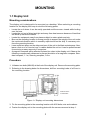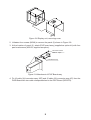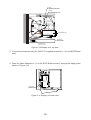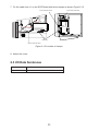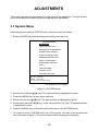
1
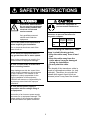
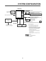
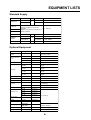
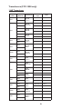
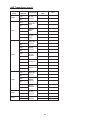
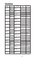
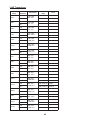
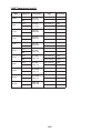
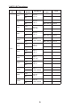
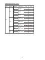
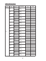
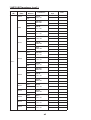
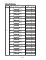
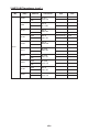
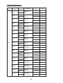
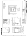
Back
Installation Manual
COLOR VIDEO SOUNDER FCV-1500
COLOR VIDEO MONITOR FCV-1500M
SAFETY INSTRUCTIONS ...................................................... i
SYSTEM CONFIGURATION ................................................ ii
EQUIPMENT LISTS ................................................................. iii
MOUNTING
1.1 Display Unit ..........................................................................1
1.2 Transducer (FCV-1500 only) ................................................2
1.3 Optional Water Temperature Sensors..................................2
WIRING
2.1 General Wiring .....................................................................4
2.2 Connection of Optional Equipment ...................................... 6
2.3 I/O Data Sentences ........................................................... 11
ADJUSTMENTS
3.1 System Menu .....................................................................12
3.2 Transducer Setting (FCV-1500 only) ................................. 13
3.3 Adjustment for Transmitter Unit/Telesounder/
Picture Recorder ................................................................ 16
3.4 Nav Data Setting ................................................................ 19
3.5 Picture Adjustment ............................................................. 20
3.6 DIP Switch Settings for EXIF Board .................................. 21
APPENDIX ........................................................... AP-1
PACKING LISTS .................................................................... A-1
OUTLINE DRAWING ........................................................... D-1
INTERCONNECTION DIAGRAM ................................... S-1
Your Local Agent/Dealer
9-52 Ashihara-cho,
Nishinomiya, Japan
Telephone :
0798-65-2111
fax
0798-65-4200
:
All rights reserved.
Printed in Japan
FIRST EDITION : APR. 1999
K1
PUB.No. IME-23630-K1
( DAMI ) FCV-1500/M
: DEC. 12,2003
*00080867401*
*00080867401*
*00080867401*
*IME23630K10*
*IME23630K10*
*IME23630K10*
SAFETY INSTRUCTIONS
WARNING
CAUTION
ELECTRICAL SHOCK HAZARD
Ground the equipment to
prevent mutual interference.
Do not open the equipment
unless totally familiar with
electrical circuits and
service manual.
Observe the following compass safe
distances to prevent deviation of a
magnetic compass:
Only qualified personnel
should work inside the
equipment.
Standard
compass
Turn off the power at the switchboard
before beginning the installation.
Display
unit
Fire or electrical shock can result if the
power is left on.
1.1 m
Steering
compass
0.8 m
When handling the transducer cable,
keep in mind following points.
• Keep the cable away from oil and
fuel.
• Keep the cable away from the
place where it may be damaged
during the installation.
• Do not paint the cable.
Do not install the equipment where it
may get wet from rain or water splash.
Water in the equipment can result in fire,
electrical shock or equipment damage.
Be sure no water leaks in at the transducer mounting location.
The sheath of the transducer cable is
made of chlorophrene rubber (or vinyl
chloride). Therefore, do not paint the
sheath with organic liquid (such as
toluene) since it may harm the sheath.
Water leakage can sink the vessel. Also
confirm that the transducer will not loosen
by ship’s vibration. The installer of the
equipment is solely responsible for the
proper installation of the equipment.
FURUNO will assume no responsibility for
any damage associated with improper
installation.
Be sure that the power supply is
compatible with the voltage rating of
the equipment.
Connection of an incorrect power supply
can cause fire or equipment damage. The
voltage rating of the equipment appears
on the label above the power connector.
i
i
SYSTEM CONFIGURATION
Display Unit
CV-1500/1500M
Navigator
External
Monitor
Color Monitor
Interface
OP02-76
(Internal)
Interface
VI-1100A
Transmitter unit (ETR-2D etc.)
High resolution transceiver unit (IS-73)
Telesounder (TS-7000)*3
Water Temperature Sensor
Transmitter unit (ETR-2D etc.)
High resolution transceiver unit (IS-73)
Telesounder (TS-7000)*3
Same as above.
Switch Box
Same as above.
EX-7
Same as above.
*2
Picture recorder (MT-12)
Rectifier
RU-1746B-2
Ship's Mains
24/32 VDC
AC100/110/115/200/
220/230V, 1φ, 50/60Hz
Sonar, telesounder (TS-50/80)*3,
net recoder
Transducer*1 Transducer*1
*1 : FCV-1500 only
*2 : FCV-1500M, FCV-1500 with the
EXIF Board assy (option) only
*3 : Master ship; FCV-1500M, FCV-1500
with the EXIF Board assy are available.
Sister ship; FCV-1500 with the EXIF
Board Assy (option) only.
One external unit is connectable on
the sister ship.
Output signal is one frequency only.
: Option
: Connectable External
Equipment
ii
EQUIPMENT LISTS
Standard Supply
Name
Type
Qty
Code No.
CV-1500
Display Unit
Remarks
–
For FCV-1500
–
For FCV-1500M
1
CV-1500M
Select from 1, 2 or 3kW transducer,
referring to page iv to xv and the
Appendix.
Selection not necesary if transducer is
already installed.
FCV-1500 only
Spare Parts
SP02-04001
Fuse
Installation
Materials
CP02-06201
Accessories
Transducer
Thru-hull Pipe
Transducer Tank
1 set 001-396-930
001-396-940
For FCV-1500
CP02-06202
001-399-090
For FCV-1500M
FP02-04900
1 set 000-012-375
1 set
Filter
Optional Equipment
Name
Color Monitor
Interface
Water Temperature
Sensor
Rectifier
Type
Code No.
Remarks
Includes CMIF assy., XH connector,
M3X10 screw, clamp
OP02-76
000-012-377
T-02MSB
000-040-040
Thru-hull type
T-02MTB
000-040-026
Transom mount, with 8 m cable
T-03MSB
000-040-027
Thru-hull type, with 8 m cable
RU-1746B-2
000-030-439
AC → DC
MJ-A6SPF
0012-050
000-134-424
6P-6P, 5 m, for connection of
navigator
MJ-A6SPF
0012-100
000-133-817
6P-6P, 10 m, for connection of
navigator
MJ-A6SPF
0011-050
000-132-244
6P-4P, 5 m, for connection of
navigator
MJ-A6SPF
0011-100
000-132-336
6P-4P, 10 m, for connection of
navigator
Cable Assy.
Vinyl Cover
10-026-0601
000-800-199-0 4
Hood
FP02-02610
002-007-280
Vinyl Wire
KIV2.0SQ, Black
000-554-516
For earth
000-506-505
For connection of transducer
(FCV-1500 only)
FM14-8P
000-511-408
For FNZ-18
OP03-70
008-423-420
ETR-2D
000-001-548
NCS-254-P
Connector
Handle
ETR-3D
000-001-54 9
ETR-5D
000-001-578
Transmitter Unit
ETR-10D
000-001-579
High Resolution
Transceiver Unit
IS-73
000-000-143
Interface
VI-1100A
000-021-805
Switch Box
EX-7
000-027-553
Cable Assy.
NCS255AD254P-L500
000-142-518
For FCV-1500, dual frequency
transducer installation.
EXIF Board assy
OP02-77
000-012-378
For FCV-1500 only
Booster Box
BT-5
-
FCV-1500M only
For FCV-1500 only
iii
Transducers (FCV-1500 only)
1 kW Transducer
Frequency
(kHz)
Hull
Material
Steel
15/45
FRP
Steel
FRP
Steel
15/50
FRP
Steel
FRP
Steel
15/68
FRP
Steel
15/88
FRP
Steel
15/200
FRP
Steel
28/45
FRP
Steel
FRP
Steel
28/50
FRP
Steel
FRP
Steel
28/68
FRP
Steel
28/88
FRP
Steel
28/200
FRP
Steel
45/88
FRP
Transducer
Thru-Hull
Pipe
Tank
15F-4S
45F-3H
15F-4S
50B-6/6B
15F-4S
50B-9B
15F-4S
50F-8G
15F-4S
68F-8H
15F-4S
88B-8
15F-4S
200B-5S
28F-8
45F-3H
28F-8
50B-6/6B
28F-8
50B-9B
TWB-6000 (2) T-656
28F-8
50F-8G
28F-8
68F-8H
28F-8
88B-8
TWB-6000 (2) T-657
28F-8
200B-5S
45F-3H
88B-8
iv
1 kW Transducer (con’t.)
Frequency
(kHz)
Hull
Material
Steel
45/200
FRP
Steel
FRP
Steel
50/88
FRP
Steel
FRP
Steel
FRP
Steel
FRP
Steel
50/200
FRP
Transducer
Thru-Hull
Pipe
45F-3H
200B-5S
50B-6/6B
88B-8
50B-9B
88B-8
TWB-6000 (2) T-658
50F-8G
88B-8
50B-6/6B
200B-5S
50B-9B
200B-5S
50F-8G
200B-5S
Steel
50/200-1T
FRP
Steel
50/200-1ST
FRP
Steel
FRP
Steel
50/400
FRP
Steel
FRP
Steel
68/200
FRP
88/200
Steel
FRP
Tank
50B-6/6B
400B-52
50B-9B
400B-52
50F-8G
400B-52
68F-8H
200B-5S
88B-8
200B-5S
v
2 kW Transducer
Frequency
(kHz)
Hull
Material
Steel
15/45
FRP
15/50
15/68
Steel
FRP
Steel
FRP
Steel
15/88
FRP
Steel
15/200
FRP
Steel
28/45
FRP
Steel
28/50
FRP
Steel
28/68
FRP
Steel
28/88
FRP
Steel
28/200
FRP
Steel
45/88
FRP
45/200
Steel
FRP
Steel
50/88
FRP
Steel
50/200
FRP
Steel
68/200
FRP
88/200
Steel
FRP
Transducer
Thru-Hull
Pipe
Tank
15F-10
45F-6H
15F-10
50B-12
TFB-7000 (2) T-627
15F-10
68F-30H
15F-10
88B-10
15F-10
200B-8/8B/8N
TFB-7000 (2) T-629
TRB-1100 (2) T-629-F
TFB-7000 (2) T-632
TRB-1100 (2) T-632-F
28F-18
45F-6H
28F-18
50B-12
28F-18
68F-30H
28F-18
88B-10
28F-18
200B-8/8B/8N
TFB-7000 (2) T-634
TRB-1100 (2) T-634-F
TFB-7000 (2) T-636
TRB-1100 (2) T-636-F
TFB-7000 (2) T-638
TRB-1100 (2) T-638-F
45F-6H
88B-10
45F-6H
200B-8/8B/8N
50B-12
88B-10
50B-12
200B-8/8B/8N
68F-30H
200B-8/8B/8N
88B-10
200B-8/8B/8N
TFB-7000 (2) T-643
TRB-1100 (2) T-643-F
TFB-7000 (2) T-645
TRB-1100 (2) T-645-F
TFB-7000 (2) T-649
TRB-1100 (2) T-649-F
vi
3 kW Transducer
Frequency
(kHz)
Hull
Material
Steel
15/45
FRP
Steel
15/50
FRP
Steel
15/68
FRP
Steel
15/88
FRP
Steel
15/107
FRP
Steel
15/150
FRP
Steel
15/200
FRP
Steel
28/45
FRP
Steel
28/50
FRP
Steel
28/68
FRP
Steel
28/88
FRP
Steel
28/107
FRP
Steel
28/150
FRP
Steel
28/200
FRP
Steel
45/88
FRP
Steel
45/107
FRP
Steel
45/150
FRP
Transducer
Thru-Hull
Pipe
Tank
15F-10X2
45F-12H
15F-10X2
50F-24H
15F-10X2
68F-30H
15F-10X2
88F-126H
15F-10X2
100B-10R
15F-10X2
150B-12H
15F-10X2
200B-12H
28F-24H
45F-12H
28F-24H
50F-24H
TFB-7000 (2) T-681
TRB-1100 (2) T-681-F
28F-24H
68F-30H
28F-24H
88F-126H
TFB-7000 (2) T-682
TRB-1100 (2) T-682-F
28F-24H
100B-10R
28F-24H
150B-12H
28F-24H
200B-12H
TFB-7000 (2) T-683
TRB-1100 (2) T-683-F
TFB-7000 (2) T-683
TRB-1100 (2) T-683-F
45F-12H
88F-126H
45F-12H
100B-10R
45F-12H
150B-12H
vii
3 kW Transducer (con’t.)
Frequency
(kHz)
Hull
Material
Steel
45/200
FRP
Steel
50/88
FRP
Steel
50/107
FRP
Steel
50/150
FRP
Steel
50/200
FRP
Steel
68/107
FRP
Steel
68/150
FRP
Steel
68/200
FRP
Steel
88/150
FRP
Steel
88/200
FRP
Steel
107/200
FRP
Transducer
Thru-Hull
Pipe
Hull Tank
45F-12H
200B-12H
50F-24H
88F-126H
TFB-7000 (2) T-682
TRB-1100 (2) T-682-F
50F-24H
100B-10R
50F-24H
150B-12H
TFB-7000 (2) T-683
50F-24H
200B-12H
TFB-7000 (2) T-683
TRB-1100 (2) T-683-F
TRB-1100 (2) T-683-F
68F-30H
100B-10R
68F-30H
150B-12H
TFB-7000 (2) T-646
68F-30H
200B-12H
TFB-7000 (2) T-646
TRB-1100 (2) T-646-F
TRB-1100 (2) T-646-F
88F-126H
150B-12H
88F-126H
200B-12H
TFB-7000 (2) T-685
TRB-1100 (2) T-685-F
100B-10R
200B-12H
viii
1 kW/2 kW Transducer
Output
(W)
Frequency
(kHz)
Hull
Material
Steel
15/45
FRP
Steel
15/50
FRP
Steel
15/68
FRP
Steel
15/88
FRP
Steel
15/200
FRP
Steel
28/45
FRP
Transducer
Thru-hull
Pipe
Tank
15F-4S
45F-6H
TFB-7000 (2) T-626
15F-4S
50B-12
TRB-1100 (2) T-626-F
15F-4S
68F-30H
TWB-6000 (2) T-628
15F-4S
88B-10
TRB-1100 (2) T-628-F
15F-4S
200B-8/8B/8N
TWB-6000 (2) T-631
TRB-1100 (2) T-631-F
28F-8
45F-6H
1 k/2 k
Steel
28/50
FRP
Steel
28/68
FRP
Steel
28/88
FRP
Steel
28/200
FRP
Steel
45/88
FRP
Steel
45/200
FRP
28F-8
50B-12
28F-8
68F-30H
28F-8
88B-10
28F-8
200B-8/8B/8N
45F-3H
88B-10
45F-3H
200B-8/8B/8N
ix
TWB-6000 (2) T-657
1 kW/2 kW Transducer (con’t.)
Output
(W)
Frequency
(kHz)
Hull
Material
Steel
FRP
Steel
50/88
FRP
Steel
FRP
Steel
FRP
Transducer
Thru-hull
Pipe
Tank
50B-6/6B
88B-10
50B-9B
88B-10
TFB-7000 (2) T-636
50F-8G
88B-10
TRB-1100 (2) T-636-F
50B-6/6B
200B-8/8B/8N
1 k/2 k
Steel
50/200
FRP
Steel
FRP
Steel
68/200
FRP
Steel
88/200
FRP
50B-9
200B-8/8B/8N
50F-8G
200B-8/8B/8N
TWB-6000 (2) T-658
TFB-7000 (2) T-638
TRB-1000 (2) T-638-F
68F-8H
200B-8/8B/8N
88B-8
200B-8/8B/8N
x
TWB-6000 (2) T-659
1 kW/3 kW Transducer
Output
(W)
Frequency
(kHz)
Hull
Material
Steel
15/45
FRP
Steel
15/50
FRP
Steel
15/68
FRP
Steel
15/88
FRP
Steel
15/107
FRP
Steel
15/150
FRP
Steel
15/200
FRP
Steel
28/45
FRP
Steel
1 k/3 k
28/50
FRP
Steel
28/68
FRP
Steel
28/88
FRP
Steel
28/107
FRP
Steel
28/150
FRP
Steel
28/200
FRP
Steel
45/88
FRP
Steel
45/107
FRP
Steel
45/150
FRP
Transducer
Thru-Hull
Pipe
Tank
15F-4S
45F-12H
15F-4S
50F-24H
15F-4S
68F-30H
15F-4S
88F-126H
15F-4S
100B-10R
TFB-7000 (2) T-637
15F-4S
150B-12H
TRB-1100 (2) T-637-F
15F-4S
200B-12H
28F-8
45F-12H
28F-8
50F-24H
28F-8
68F-30H
28F-8
88F-126H
28F-8
100B-10R
28F-8
150B-12H
28F-8
200B-12H
45F-3H
88F-126H
45F-3H
100B-10R
45F-3H
150B-12H
xi
1 kW/3 kW Transducer (con’t.)
Output
(W)
Frequency
(kHz)
Hull
Material
Steel
45/200
FRP
Steel
FRP
Steel
50/88
FRP
Steel
FRP
Steel
FRP
Steel
50/107
FRP
Steel
FRP
Steel
FRP
Steel
50/150
FRP
1 k/3 k
Steel
FRP
Steel
FRP
Steel
50/200
FRP
Steel
FRP
Steel
68/107
FRP
Steel
68/150
FRP
Steel
68/200
FRP
Steel
88/150
FRP
Steel
88/200
FRP
Transducer
45F-3H
200B-12H
50B-6/6B
88F-126H
50B-9B
88F-126H
50F-8G
88F-126H
50B-6/6B
100B-10R
50B-9B
100B-10R
50F-8
100B-10R
50B-6/6B
150B-12H
50B-9B
150B-12H
50F-8G
150B-12H
50B-6/6B
200B-12H
50B-9B
200B-12H
50F-8G
200B-12H
68F-8H
100B-10R
68F-8H
150B-12H
68F-H
200B-12H
88B-8
150B-12H
88B-8
200B-12H
xii
Thru-Hull
Pipe
Tank
2 kW/3 kW Transducer
Output
(W)
Frequency
(kHz)
Hull
Material
Steel
15/45
FRP
Steel
15/50
FRP
Steel
15/68
FRP
Steel
15/88
FRP
Steel
15/107
FRP
Steel
15/150
FRP
Steel
15/200
FRP
Steel
28/45
FRP
Steel
2 k/3 k
28/50
FRP
Steel
28/68
FRP
Steel
28/88
FRP
Steel
28/107
FRP
Steel
28/150
FRP
Steel
28/200
FRP
Steel
45/88
FRP
Steel
45/107
FRP
Steel
45/150
FRP
Transducer
Thru-Hull
Pipe
Tank
15F-10
45F-12H
15F-10
50F-24H
15F-10
68F-30H
15F-10
88F-126H
15F-10
100B-10R
15F-10
150B-12H
15F-10
200B-12H
28F-18
45F-12H
28F-18
50F-24H
28F-18
68F-30H
28F-18
88F-126H
28F-18
100B-10R
TFB-7000 (2) T-636
28F-18
150B-12H
TFB-7000 (2) T-637
28F-18
200B-12H
45F-6H
88F-126H
45F-6H
100B-10R
45F-6H
150B-12H
xiii
TRB-1100 (2) T-636-F
TRB-1100 (2) T-637-F
2 kW/3 kW Transducer (con’t.)
Output
(W)
Frequency
(kHz)
Hull
Material
Steel
45/200
FRP
Steel
50/88
FRP
Steel
50/107
FRP
Steel
50/150
FRP
Steel
50/200
FRP
Transducer
Steel
FRP
Steel
68/150
FRP
Steel
68/200
FRP
Steel
88/150
FRP
Steel
88/200
FRP
Tank
45F-6H
200B-12H
50B-12
88F-126H
50B-12
100B-10R
50B-12
150B-12H
50B-12
200B-12H
2 k/3 k
68/107
Thru-Hull
Pipe
68F-30H
100B-10R
68F-30H
150B-12H
68F-30H
200B-12H
88B-10
150B-12H
88B-10
200B-12H
xiv
TFB-7000 (2) T-643
TRB-1100 (2) T-643-F
TFB-7000 (2) T-644
TRB-1100 (2) T-644-F
3 kW/2 kW Transducer
Output
(W)
Frequency
(kHz)
Hull
Material
Steel
15/45
FRP
Steel
15/50
FRP
Steel
15/68
FRP
Steel
15/88
FRP
Steel
15/200
FRP
Steel
28/45
FRP
Steel
28/50
FRP
Steel
28/68
FRP
Steel
3 k/2 k
28/88
FRP
Steel
28/200
FRP
Steel
45/88
FRP
Steel
45/200
FRP
Steel
50/88
FRP
Steel
50/200
FRP
Steel
68/200
FRP
Steel
88/200
FRP
Steel
100/200
FRP
Transducer
Thru-Hull
Pipe
Tank
15F-10X2
45F-6H
15F-10X2
50B-12
15F-10X2
68F-30H
15F-10X2
88B-10
15F-10X2
200B-8/8B/8N
28F-24H
45F-6H
28F-24H
50B-12
28F-24H
68F-30H
28F-24H
88B-10
28F-24H
200B-8/8B/8N
45F-12H
88B-10
45F-12H
200B-8/8B/8N
50F-24H
88B-10
50F-24H
200B-8/8B/8N
68F-30H
200B-8/8B/8N
TFB-7000 (2) T-647
TRB-1100 (2) T-647-F
88F-126H
200B-8N
100B-10R
200B-8/8B/8N
xv
TFB-7000 (2) T-649
TRB-1100 (2) T-649-F
MOUNTING
1.1 Display Unit
Mounting considerations
The display unit is designed to be mounted on a desktop. When selecting a mounting
location for the display unit keep in mind the following points.
• Locate the unit where it can be easily operated and the screen viewed while looking
over the bow.
• Locate the unit out of direct sunlight and away from heat sources because of heat that
can build up inside the cabinet.
• Locate the equipment away from places subject to water splash and rain.
• Be sure the mounting location is strong enough to support the weight of the unit under
the continued vibration which is normally experienced on the ship. If necessary reinforce the mounting location.
• Leave sufficient space on the sides and rear of the unit to facilitate maintenance. Also,
leave a foot or so of “service loop” in cables behind the unit so it can be pulled forward
for servicing or easy removal of connectors.
• A magnetic compass will be affected if placed too close to the display unit. Observe the
following compass safe distances to prevent deviation of a magnetic compass: Standard compass, 1.1 m, Steering compass, 0.8 m.
Procedure
1. Unfasten two bolts (M8X40) at the front of the display unit. Remove the mounting plate.
26
26
72
4-φ12
200
490
160
200
100
2. Referring to the drawing below for dimensions, drill four mounting holes of ø12 mm in
the mounting location.
100
400
100
All dimensions
in millimeters
Figure 1-1 Display unit mounting dimensions
3. Fix the mounting plate to the mounting location with M10 bolts, nuts and washers.
4. Fasten the display unit to the mounting plate with the screws removed at step 1.
1
1.2 Transducer (FCV-1500 only)
The performance of the color video sounder greatly depends on the transducer location. A
place least affected by air bubbles should be selected since turbulence interferes with
sounding. Also, select a place least influenced by engine noise. It is known that bubbles
are at a minimum, at normal cruising speed, at the location where the first bow wave falls
and the next wave rises. On small, low speed boats, the position between 1/3 and 1/2 of
ship’s length from the bow is usually a good place. The face of the transducer must be
facing the sea bottom in normal cruising trim of the ship.
1.3 Optional Water Temperature Sensors
Transom mount water temperature sensor T-02MTB
Select a suitable mounting location considering the following:
• Fix the cable at a convenient location with a cable clamp.
• When the cable is to be led in through the transom board, make a hole of approx. 17
mm in diameter to pass the connector. After passing the cable through the hole, fill the
hole with a suitable sealing compound.
D>50 cm
D
Tapping
Screw
(M5X20)
Mount sensor flush
with hull bottom.
Figure 1-2 How to install transom mount water temperature sensor T-02MTB
2
Thru-hull mount water temperature sensor T-02MSB, T-03MSB
When selecting a mounting location for the sensor keep in mind the following points:
• Select a mid-boat flat position.
• The sensor does not have to be installed perfectly perpendicular, however it must not
be located where it won’t be damaged when the boat is dry docked.
• Select a place apart from equipment generating heat.
• Select a place in the forward direction viewing from the drain hole, to allow for circulation of cooling water.
• Select a place free from vibration.
T-02MSB
T-03MSB
Sensor Holder
Sensor
Cable
Lock Nut
Lock Nut
Washer
Rubber Gasket
Lock Nut
Washer
φ21 mm
Rubber Gasket
φ25 mm
Apply sealant.
Apply sealant.
1. Drill a hole of φ21 mm in the hull.
2. Pass the sensor cable through the hull.
3. Pass the rubber gasket, washer and lock
nut onto the cable in that order.
4. Apply high-grade sealant to the sensor
flange, sensor and lock nut. Tighten the
lock nut. Do not overtighten it; torque
should be less than 59N•m.
5. Launch the boat and check for water
leakage around the sensor.
Holder Guide
Thickness within
25 mm
1. Drill a hole of φ25 mm in the hull.
2. Coat the holder guide with sealant, and then
pass it through the hull from outside the boat.
3. Pass the rubber gasket, washer and lock nut
onto the holder guide in that order. Tighten the
lock nut. Torque should be less than 59N•m.
4. Lead in the sensor holder from inside the boat
and set it to the holder guide. Tighten the lock
nut.
5. Launch the boat and check for water leakage
around the sensor.
Figure 1-3 How to mount thru-hull mount water temperature sensors T-02MSB, T-03MSB
3
WIRING
All wiring is terminated at the rear of the display unit. The power and transducer cables
must be fitted with a connnector in the field. The water temperature sensor (option) cable
is prefitted with a connector. For detailed information see the interconnection diagram at
the end of this manual.
External Interface connector*2 (24P)
HIGH
LOW
HIGH
NMEA Connector
TEMP Connector
SONDE Connector
LOW
TRANSDUCER Connector*1
(4P)
Fuse (15A)
POWER
Connector
Earth Terminal
*1: FCV-1500 only, FCV-1500M is covered.
*2: FCV-1500M only, FCV-1500 is covered.
Figure 2-1 Display unit, rear view
2.1 General Wiring
Transducer (FCV-1500 only)
Separate the transducer cable as far apart as possible from other cables to prevent interference to this equipment. Fabricate the transducer cable as below and connect it to the
appropriate TRANSDUCER connector on the rear panel.
Shield
Clamp at shield.
2
3
4
Cable
Connector
Cable Clamp
Note: For the dual frequency transducer
connection, use the NCS255AD-L-500
cable assy (option).
Figure 2-2 How to attach connector to transducer cable
4
External interface (FCV-1500M only)
When the external equipment (E/S, Transmitter unit, Switch box) is connected, attach the
SRCN6A25-24P connector (installation materialls) to the cable.
Note:The EXIF Board assy (option) enables connection of the FCV-1500 to other equipment. SRCN6A25-24P connectosr are supplied with this option in the box.
1. Solder the cable to the connector pins.
Remove connector clamp.
Sheath
Cable
Cable sheild
Solder wires to the each pin.
Pass the connector shell thru the cable.
2. Wind sheild tape supplied.
Sheath
Shield tape
3. Screw the shell on the connector. Fix the connector onto the cable by tightening the clamp.
Clamp
Sheath
Shield tape
Figure 2-3 SRCN6A25-24P connector fablication
Power supply
The display unit is powered by a 24 or 32 VDC power supply (20-40 VDC). The length of
the power cable (type DPYCYS-3.5, or equivalent) should be as short as possible. Plug
the power cable in the POWER connector at the rear of the display unit and connect the
leads to the power supply; white lead to positive (+), black lead to minus (-). Clamp the
shield with the connector.
Taping
Shield
Sheath
Armor
Clamp at armor.
#1 pin (+)
#2 pin (-)
#3 pin
Core
2
S = 3.5 mm
= 2.4 mm
Vinyl Sheath
Figure 2-4 How to attach connector to power cable DPYCYS-3.5
5
Earth
CAUTION
Fasten the copper strap (supplied) between the
earth terminal on the display unit and the ship’s
superstructure.
Ground the equipment to
prevent electrical shock
and mutual interference.
2.2 Connection of Optional Equipment
Navigator
Use cable type MJ-A6SPF0011/0012 (option) to connect a navigator (GPS, etc.) to the
NMEA connector at the rear of the display unit. For details, see the interconnection diagram at the end of this manual.
Water temperature sensor (T-02MSB, T-02MTB, T-03MSB)
Connect the water temperature sensor to the TEMP connector at the rear of the display
unit.
Note: The navigator and the water temperature sensor use the same type of connector.
Be sure not to confuse them when connecting.
Net Sonde FNZ-18
Use connector type FM14-8P (optional supply) and 5-twisted pair cable type CO-SPEVVSB-CO 0.2X5P (optional supply). Attach the connector to the cable as below. Connect the
cable between the CIF port on the display unit of the FNZ-18 and the SONDE connector at
the rear of the display unit. Be sure the shield of the interconnection cable lies in the cable
clamp of the connector (both FNZ-18 and FCV-1500/M). (Analog sonde signal and sonde
temperature are also available. For details see the interconnection diagram at the end of
this manual and the installation manual of the FNZ-18.)
1. Remove sheath
by 15 mm.
2. Fold back the shield onto
the cable; cut unused cores.
Vinyl tape
3. Solder cores to connector
pins; clamp shield.
4. Tape shield with vinyl tape.
(Be sure no gap exists
between clamp and tape.)
Figure 2-5 How to attach FM14-8P connector
6
Color monitor interface
The optional Color Monitor Interface is required to connect a standard VGA monitor. Supply monitor and interconnection cable locally.
Contents of Color Monitor Interface Kit (Type: OP02-76, Code No.: 000-012-377)
Name
Type
Qty
Code No.
Remarks
RGB-BUFF pcb
CMIF Assy.
OP02-76
1
001-396-910
XH Connector
02-986 (13-13P)
1
001-396-740
Clamp
No.1197
1
000-515-870
Pan-head Screw
M3X10
4
000-881-105
C2700W, MBN12
1. Unfasten eight binding screws (M4X8) to dismount the cover.
2
C
E
W
A
R
N
IN
G
Figure 2-6 Display unit, cover removed
2. Unfasten four screws (M3X6) to dismount panel 2 shown in Figure 2-3. These screws
may be discarded.
3. At the location of panel 2, orient the CMIF assy (supplied) as shown in Figure 2-4 on
the next page. Fasten the CMIF assy. with four pan-head screws (M3X10, supplied).
4. Connect the XH connector (13-13P, supplied) between the INTERFACE Board on the
CMIF assy. and J9 on the MAIN Board.
5. Insert clamp at location shown in Figure 2-4. Set cable to clamp.
7
XH Connector (13-13P)
J9
MAIN
02P6255
CMIF
Assy.
Set clamp here.
Figure 2-7 Display unit, right side view
6. Attach the cover.
EXIF Board assy (option)
When connecting telesounder or picture recorder with FCV-1500, the following option kit
is necessary.
Contents of EXIF Board assy (Type: OP02-77, Code No.: 000-012-378)
Name
Type
EXIF Board assy
Qty
Code No.
1
-
Cable assy
81-548-0776
1
000-142-526
Connector
SRCN6A25-24P
2
000-508-676
Pan-head Screw
M3X10
4
000-807-900
Remarks
EXIF pcb assembly
For other equipment
connection
1. Unfasten eight screws (M4x8) to remove the display unit cover.
8
2
CE
A
R
N
IN
G
W
Figure 2-8 Display unit, removing cover
2. Unfasten four screws (M3X8) to remove the panel (2) shown in Figure 2-8.
3. At the location of panel (2), attach EXIF board assy (supplied as option kit) with four
pan head screws (M3X10, supplied as option).
Pan-head screws
M3X10 4 pcs.
EXIF Board assy
Figure 2-9 Attachment of EXIF Board assy
4. Fix J2 cable (XH connector assy, 20P) and J5 cable (XH connector assy, 4P) from the
PWR Board with two cable clamps attached to the EXIF Board (02P6278).
9
J2 cable
XH Connector assy, 20P
J5 cable
XH Connector assy, 4P
J6
J5
J2
J4
PWR
02P6256
J3
Fix with
clamps.
EXIF Board assy
J1
Cable assy
81-548-0776
Edge guard
Figure 2-10 Display unit, top view
5. Connect the connector assy (81-548-0776, supplied as option) to J1 on the EXIF Board
assy.
6. Pass the cable attached to J1 on the EXIF Board at step 5 through the edge guard
shown in Figure 2-10.
J9
J5
J4
J1
J3
MAIN
02P6255
J2
J8
Cable assy
81-548-0776
J6
J7
Figure 2-11 Display unit, side view
10
7. Fix the cable from J1 on the EXIF Board with three clamps as shown Figure 2-12
Fix the cable with clamp.
Fix the cable with clamp.
J9
J5
J4
J1
J3
MAIN
02P6255
J2
J8
J6
J7
DANGER
Cable assy
Fix the cable with clamp.
Figure 2-12 Location of clamps
8. Attach the cover.
2.3 I/O Data Sentences
Input Sentences
RMA, RMC, GLL, GTD, GLC, VTG, MTW, GGA
Output Sentences
DBT, DPT, DBS, MTW, TLL, SDVRM
11
ADJUSTMENTS
This section provides the procedures for initial set up of the equipment. The type of transducer used should be properly set before operating the equipment.
3.1 System Menu
Initial settings are made on SYSTEM menu. Open the menu as follows.
1. Press the [PWR] key while pressing and holding down any key.
[SYSTEM MENU]
LANGUAGE
FUNCTION SETTING
NAV DATA SETTING (NMEA)
SCREEN ADJUSTMENT
USER COLOR SETTING
TRANSDUCER SETTING*
DRAFT ADJUSTMENT
DEMO MODE SETTING
TEST
TEST PATTERN
TARGET ECHO
FACTORY SETTING
[▲] [▼] : Select item.
[MENU] : Open menu.
Turn off power to activate settings.
*Not available on FCV-1500M.
Figure 3-1 SYSTEM menu
2. Select menu with the [▲]/[▼] key. The selected item is highlighted in green.
3. Press the [MENU] key to open menu selected.
4. Select item with the [▲]/[▼] key. The selected item is highlighted in green.
5. Select option with the [t]/[s] key, or set value with the [+]/[-] key. The selected option
is highlighted in white.
6. Press the [MENU] key to close the menu and return to the SYSTEM menu.
7. To escape from the SYSTEM menu turn off the power, and wait a few seconds and
then the power on again. (This must be done when changing the language.)
12
3.2 Transducer Setting (FCV-1500 only)
Select the type of transducer used as follows:
Automatic selection of transducer
1. Select TRANSDUCER SETTING from the SYSTEM menu and press the [MENU] key.
(Refer to page 3-1 for how to display the SYSTEM menu.)
[TRANSDUCER SETTING]
XDR SELECT
:
TYPE
MANUAL
FREQUENCY
:
LO-FREQ
---kHz
HI-FREQ
--- kHz
TRANSDUCER
:
---
---
OUTPUT POWER :
SUPPLY VOLTAGE :
IMPEDANCE
:
FACTORY SETTING :
CAUTION
--W
--V
--Ω
--W
-- V
--Ω
Confirm type of transducer used before
setting type on the menu.
YES
NO
For using SURFACE on the TARGET
ECHO menu, the surface-use 1 kW
transducer should be connected.
Wrong transducer setting may damage the
transducer and void the warranty.
(Select 'YES' & Press [MENU] to default setting. )
<Valid for this page>
Use of it with another transducer may
result in damage to the transducer.
Warning: Changing power settings can damage
your transducer! Please confirm your
transducer's power and frequency rating.
[▲] [▼] : Select item.
[t] [s] : Change setting. (or [+], [-])
[MENU] : Return to SYSTEM MENU.
Figure 3-2 TRANSDUCER SETTING menu
2. Select TYPE.
3. Select LO-FREQ or HI-FREQ with the arrow keys.
4. Set transducer frequency with [+]/[-] key.
5. Press [▼] to select the TRANSDUCER field.
13
6. Press [+]/[-] to display transducer list. The illustration below shows the available 50
kHz transducers.
[50 kHz]
1kW :
2kW
:
3kW
:
50B-6/6B
50B-9/9B
50F-8G
50/200-1ST
50/200-1T
50B-12
50/200/400
50BL_12HR
50F-24H
50/3K/3F
50BL-24HR
[▲/▼] : Select transducer.
[MENU] : Save & Exit.
Figure 3-3 Transducer selection screen (50 kHz)
7. Select transducer type with [▲]/[▼] and then press the [MENU] key. The values for
output power, supply voltage and impedance are automatically set.
8. For 2nd transducer, select appropriate transducer as above.
9. Press the [MENU] key to close the menu and return to the SYSTEM menu.
Manual selection of transducer
If the transducer to be used is not shown on the transducer list, manually set transducer
type as below.
Note 1: When transducer 50/200-1T or 50/200-12M is used, set 50 kHz to 50B-6/6B; 200
kHz to 200B-5S. This is necessary until 50/200-1T and 50/200-12M are added to system
program.
Note 2: Max. output on transducers 50F-38 and 28F-38 is 3 kW.
1. Select TRANSDUCER SETTING from the SYSTEM menu and press the [MENU] key.
(Refer to page 3-1 for how to display the SYSTEM menu.)
2. Select MANUAL to display the following menu.
XDR SELECT
:
FREQUENCY
:
SUPPLY VOLTAGE :
IMPEDANCE
:
TYPE
MANUAL
LO-FREQ
HI-FREQ
50 kHz
46 V
320Ω
CAUTION
Do not manually set transducer type if
type used is programmed in this unit.
200 kHz
75 V
100Ω
Wrong transducer setting may damage the
transducer and void the warranty.
Figure 3-4 Manual Transducer selection screen
14
3. Select HI-FREQ or LO-FREQ with the arrow keys.
4. Use the [+]/[-] key to set frequency.
5. Press [▼] to select SUPPLY VOLTAGE.
6. Set supply voltage with [+]/[-] key.
7. Press [▼] to select IMPEDANCE.
8. Set impedance with [+]/[-] key. (Not required; system will function properly without setting.)
9. For 2nd transducer, set it as appropriate.
10.Press the [MENU] key to return to the SYSTEM menu.
15
3.3 Adjustment for Transmitter Unit / Telesounder/
Picture Recorder
When the transmitter unit (ETR-2D etc.), video sounder, telesounder (TS-50/80/7000/8000)
or picture recorder (MT-12) is connected, do the following adjustments.
Note 1: For FCV-1500, install the EXIF Board assy (option) before the connection.
Note 2: For FCV-1500M, only master ship is available to connect to the telesounder. The
picture recorder is not available to record echo sounder signal, playback only.
Transmitter/video sounder
1. Select FUNCTION SETTING from the SYSTEM menu and press the [MENU] key.
DEPTH UNIT
:m
DEPTH SCALE
: RIGHT
ft
fa
CENTER
hiro
P/B
SCREEN DIVISION
: VERT
HOR
PICT ADVNC DIR
: LEFT
RIGHT
A-SCOPE DISP
: 1/4
1/2
SONDE TEMP DISP
: 1/4
1/2
ZOOM DISP
: FULL
PIC RECALL DISP
: FULL
PWR REDUCT (HF)*
: OFF
ON
PWR REDUCT (LF)*
: OFF
ON
TX SYNC
: INTERNAL
VERT VRM UNIT
: TIME
TEMP UNIT
: C
TEMP INPUT
: SONDE
TEMP ADJUST
: +0.0
NL METHOD
: CORREL-1
ZOOM MARKER
: OFF
ON
TS OUTPUT
: OFF
LOW-FREQ
FACTORY SETTING
: YES
NO
OFF
L/R
1/2
1/2
EXTERNAL
DISTANCE
F
SENSOR
NMEA
F (-20~+20)
CORREL-2
HI-FREQ
<Valid for this page>
(Select ’YES’ & Press [MENU] to default setting.)
[▲] [▼] : Select item.
[ ] [ ] : Change setting. (or [-], [+])
[MENU] : Return to SYSTEM MENU.
*Not available on FCV-1500M.
Figure 3-5 FUNCTION SETTING menu
2. Select TS OUTPUT with [▲]/[▼].
3. Select “OFF” with [t].
16
4. Press [MENU] key to close the menu and return to the SYSTEM menu.
5. Turn the power off and on again.
6. Display the sounder screen to measure how many feet the transmitting line of HIGH
and LOW frequencies is shifted by VRM marker.
7. Turn the power off, and on again while holding any key down.
8. Select DRAFT ADJUSTMENT menu with [▲]/[▼].
9. Press the [MENU] key.
[DRAFT ADJUSTMENT]
DRAFT ADJ (HF)
DRAFT ADJ (LF)
: +0.0 ft
+0.0 ft
(-15~+90)
(-15~+90)
DRAFT ADJ (H) EXT : +0.0 ft
DRAFT ADJ (L) EXT : +0.0 ft
(-15~+90)
(-15~+90)
[▲] [▼]
[ ] [ ]
[MENU ]
4800
: Select item.
: Change setting. (or [-], [+])
: Return to SYSTEM MENU.
Figure 3-6 DRAFT ADJUSTMENT menu
10.Enter the value of the transmitting line measured in step 6 with - (minus) at the DRAFT
ADJ (H) EXT and DRAFT (L) EXT lines with [t]/[s].
11.Press the [MENU] key to return to SYSTEM menu.
Telesounder
The FCV-1500M can be connected to a telesounder onboard a master ship and the FCV1500 can be connected to a telesounder onboard a master ship and sister ship.
1. Select FUNCTION SETTING from the SYSTEM menu.
2. Press the [MENU] key.
3. Select TS OUTPUT with [▲]/[▼].
4. When FCV-1500/FCV-1500M installed on the master ship, select OFF with [t]. When
FCV-1500 is installed on the sister ship, select LOW-FREQ or HI-FREQ with [t]/[s].
(LOW-FREQ; outputs the signal to the master ship from the low frequency port, HIFREQ; outputs the signal to the master ship from the high frequency port)
5. Press the [MENU] key to return to SYSTEM menu.
6. Turn the power off and on again.
17
7. For FCV-1500 only, do the following.
a) Press the [MENU] key.
b) Open the TX/RX menu with [+]/[-] key.
c) When your unit is on the master ship, select EXTER at TDR CNNCT (HF/LF) for
input port. When installing on the sister ship, select INTER at TDR CNNCT (HF/LF)
for output port.
8. Display the sounder screen to measure how many feet the transmitting line of HIGH
and LOW frequencies is shifted by VRM marker.
Transmitting line is low: to the next step,
Transmitting line is same position: to step 15.
9. Turn the power off, and on again while holding any key down.
10.Select DRAFT ADJUSTMENT with [▲]/[▼].
11.Press the [MENU] key.
12.At DRAFT ADJ (HF/LF) line for the sister ship, at DRAFT ADJ (HF/LF) EXT line for the
master ship, enter the value of the transmitting line measured in step 7 with - (minus).
13.Press the [MENU] key to return to SYSTEM menu.
14.Turn the power off, and on again.
15.Check the error between the display transmitted from the sister ship and the display of
own ship.
Picture recorder
The FCV-1500M can playback echo sounder signal and FCV-1500 can record/playback it.
1. Select FUNCTION SETTING from the SYSTEM menu.
2. Press the [MENU] key.
3. Select TS OUTPUT with [▲]/[▼].
4. For playback, select OFF with [t]. For recording, select LOW-FREQ or HI-FREQ with
[t]/[s]. (LOW-FREQ; outputs the signal from the low frequency port, HI-FREQ; outputs the signal from the high frequency port)
5. Press the [MENU] key to return to SYSTEM menu.
6. Turn the power off and on again.
7. For FCV-1500 only, do the following steps.
a) Press the [MENU] key.
b) Open the TX/RX menu with [+]/[-] key.
c) For playback, select EXTER at TDR CNNCT (HF/LF) line for input port. For record
ing, select INTER at TDR CNNCT (HF/LF) line for output port.
18
8. Display the sounder screen to measure how many feet the transmitting line of HIGH
and LOW frequencies is shifted by VRM marker.
Transmitting line is low: to the next step,
Transmitting line is same position: The setting is finished.
9. Turn the power off, and on again while holding any key down.
10.Select DRAFT ADJUSTMENT with [▼] key.
11.Press the [MENU] key.
12.Enter the value of the transmitting line measured in step 8 with - (minus). at the DRAFT
ADJ (H) EXT and DRAFT (L) EXT line with [t]/[s]
13.Press the [MENU] key to return to SYSTEM menu.
3.4 Nav Data Setting
1. Select NAV DATA SETTING (NMEA) from the SYSTEM menu and press the [MENU]
key.
[NAV DATA SETTING (NMEA)]
BAUD RATE (NMEA) : 600
1200
2400
NAV DATA
: DR
AUTO
LC...
NMEA VERSION
: Ver 1.5 Ver 2.0
DISPLAY DATA
: L/L
TD
TLL OUTPUT
: OFF
ON
4800
TIMER
[▲] [▼] : Select item.
[t] [s] : Change setting. (or [-], [+])
[MENU] : Return to SYSTEM MENU.
Figure 3-7 NAV DATA SETTING (NMEA) menu
2. Set baud rate of navigator with [t]/[s].
3. Select NAV DATA with [▲]/[▼].
4. Set type of NMEA talker of navigator (GPS, Loran C, Loran A, Decca, DR, AUTO) with
[t]/[s]. Select AUTO when more than one navigator is connected, and the priority is
GPS, Loran C, Loran A, Decca, DR.
5. Select NMEA VERSION with [▲]/[▼].
6. Set NMEA version of navigator with [t]/[s]. If you are unsure of version number try
both and select the one which successfully receives nav data.
7. Select DISPLAY DATA with [▲]/[▼].
8. Select L/L or TD as appropriate with [t]/[s].
9. Select TLL OUTPUT with [▲]/[▼]. (This enables/disables L/L position output when the
[MARKER] key is operated.)
10.Select ON or OFF as appropriate with [t]/[s].
11.Press the [MENU] key to close the menu and return to the SYSTEM menu.
19
3.5 Picture Adjustment
1. Select SCREEN ADJUSTMENT from the SYSTEM menu and press the [MENU] key.
[SCREEN ADJUSTMENT]
HOR. SIZE
:
+0
HOR. POSITION
:
+0
VERT. SIZE
:
+0
VERT. POSITION
:
+0
DEFLECTION DIST. :
+0
BRIGHTNESS
:
+0
BRIGHTNESS STEP :
1
(1-18)
CONTRAST MAX
:
255
(CONTRAST MIN +1 - 255)
CONTRAST MIN
:
255
(0 - CONTRAST MAX -1)
FACTORY SETTING : YES
NO <Valid for this page>
(Select ’YES’ & press [MENU] to default setting.)
[▲] [▼] : Select item.
[t] [s] : Change setting. (or [-], [+])
[MENU] : Return to SYSTEM MENU.
Figure 3-8 Screen adjustment menu
Horizontal
2. Use the [▲]/[▼] key to select item to adjust.
HOR. SIZE:
Adjusts picture size in horizontal direction.
HOR. POSITION:
Adjusts picture position in
horizontal direction.
VER. SIZE:
Adjusts picture size in verti- Vertical
cal direction.
VER. POSITION:
Adjusts picture position in
vertical direction.
DEFLECTION DIST: Corrects concave distortion.
BRIGHTNESS:
Adjusts picture brightness.
BRIGHTNESS STEP: Sets the amount of brightness levels available when changing
picture brightness.
CONTRAST MAX:
Sets contrast setting to use with maximum brightness setting
(8). (Setting cannot be lower than CONTRAST MIN setting.)
CONTRAST MIN:
Sets contrast setting to use with minimum picture brightness
is used. (Setting cannot be higher than CONTRAST MAX
setting.)
FACTORY SETTING: Restores the factory settings of this menu. (All zeroes except
CONTRAST which is 255.)
3. Use the [t]/[s] key (or[+]/[-]) key to enter appropriate value.
4. Press the [MENU] key to close the menu and return to the SYSTEM menu.
Note: Vertical and horizontal are reversed as shown right.
20
3.6 DIP Switch Settings for EXIF Board
Set the DIP switches on the EXIF Board 02P6279 according to equipment connected. No
change is necessary when connecting a video sounder which uses a linear amplifier (FCV271/382/782, etc.). For a video sounder with a log amplifier (FCV-1500, etc.) change the
DIP switch settings as below. Early model FURUNO video sounders which have a log
amplifier cannot be connected.
1 2 3 4 5 6 7 8
S2
ON
OFF
S3
1 2 3 4 5 6 7 8
ON
OFF
1 2 3 4 5 6 7 8
S1
ON
OFF
DIP switch settings on EXIF Board for linear amp
DIP SWITCH S1
DIP SWITCH S2
1 2 3 4 5 6 7 8
1 2 3 4 5 6 7 8
DIP SWITCH S3
1 2 3 4 5 6 7 8
ON
ON
ON
OFF
OFF
OFF
1:
2:
3:
4:
5:
6:
7:
KP OUT L POS (Default: ON)
KP OUT L NEG (Default: OFF)
KP IN L POS (Default: ON)
KP IN L NEG (Default: OFF
LINER IN L (Default: ON)
LOG IN L (Default: OFF)
KP IN L 12V (OFF, Default)
KP IN L 5 V (ON)
8: WL IN L 12V (OFF, Default)
WL IN L 5 V (ON)
1:
2:
3:
4:
5:
6:
7:
KP OUT H POS (Default: ON)
KP OUT H NEG (Default: OFF)
KP IN H POS (Default: ON)
KP IN H NEG (Default: OFF
LINER IN H (Default: ON)
LOG IN H (Default: OFF)
KP IN H 12V (OFF, Default)
KP IN H 5 V (ON)
8: WL IN H 12V (OFF, Default)
WL IN H 5 V (ON)
LINEAR AMP (Default setting)
Low frequency
S1-5: ON, S1-6: OFF
High frequency
S2-5: ON, S2-6: OFF
1:
2:
3:
4:
5:
6:
7:
8:
GND (Default: OFF)
KP OUT L (Default: OFF)
RECO H (Default: ON)
ETRREC H (Default: OFF)
GND (Default: OFF)
KP OUT H (Default: OFF)
RECO L (ON)
ETRREC L (Default: OFF)
ETR-2D, ETR-3D, ETR-5D/2, ETR-10D/2, EX-7
EXT-H (9 pin ... GND)
S3-1: ON, S3-2: OFF
EXT-L (9 pin ... GND)
S3-5: ON, S3:6, OFF
Note: Do not turn ON S3-1 and S3-2 or S3-5
and S3-6 together. This will short a circuit board.
LOG AMP
Low frequency
S1-5: OFF, S1-6: ON
High frequency
S2-5: OFF, S2-6: ON
DIP switch settings on EXIF Board for log amp
21
APPENDIX
NEW BLT TRANSDUCERS
A new type BLT transducer (Bolt-clamp Langevin Transducer) has been developed for this
echo sounder. The BLT has large bandwidth, good sound efficiency, compact structure
and is reinforced to protect against slamming.
Transducer, thru-hull pipe and tank list
Frequency
(kHz)
28/200
38/200
50/200
28/38
28/50
38/50
28/88
38/88
Transducer
28BL-6HR/200B-8B
38BL-9HR/200B-8B
50BL-12HR/200B-8B
28B L-12HR/38BL-15HR
28B L-12HR/50BL-24HR
38B L-15HR/50BL-24HR
28B L-12HR/88F-126H
38B L-15HR/88F-126H
Hull
Material
Tank
(Code No.)
Fasten inside
hull (Code No.)
Fasten outside
hull (Code No.)
Steel
T-693
(000-015-044)
TWB-6000 (2)
(000-015-207)
TFB-7000 (2)
(000-015-209)
FRP
T-693F
(000-015-241)
TRB-1100 (2)
(000-015-219)
-
Steel
T-693
(000-015-044)
TWB-6000 (2)
(000-015-207)
TFB-7000 (2)
(000-015-209)
FRP
T-693F
(000-015-241)
TRB-1100 (2)
(000-015-219)
-
Steel
T-693
(000-015-044)
TWB-6000 (2)
(000-015-207)
TFB-7000 (2)
(000-015-209)
FRP
T-693F
(000-015-241)
TRB-1100 (2)
(000-015-219)
-
Steel
T-681
(000-015-849)
TWB-6000 (2)
(000-015-207)
TFB-7000 (2)
(000-015-209)
FRP
T-681F
(000-015-850)
TRB-1100 (2)
(000-015-219)
-
Steel
T-681
(000-015-849)
TWB-6000 (2)
(000-015-207)
TFB-7000 (2)
(000-015-209)
FRP
T-681F
(000-015-850)
TRB-1100 (2)
(000-015-219)
-
Steel
T-681
(000-015-849)
TWB-6000 (2)
(000-015-207)
TFB-7000 (2)
(000-015-209)
FRP
T-681F
(000-015-850)
TRB-1100 (2)
(000-015-219)
-
Steel
T-682
(000-015-851)
TWB-6000 (2)
(000-015-207)
TFB-7000 (2)
(000-015-209)
FRP
T-682F
(000-015-852)
TRB-1100 (2)
(000-015-219)
-
Steel
T-682
(000-015-851)
TWB-6000 (2)
(000-015-207)
TFB-7000 (2)
(000-015-209)
FRP
T-682F
(000-015-852)
TRB-1100 (2)
(000-015-219)
-
AP-1
50/88
28/200
38/200
50/200
28/150
38/150
38/150
50B L-24HR/88-126H
28BL-12HR/200B-12H
38BL-15HR/200B-12H
50BL-24HR/200B-12H
28BL-12HR/150B-12H
38BL-15HR/150-12H
50BL-24HR/156-12H
Steel
T-682
(000-015-851)
TWB-6000 (2)
(000-015-207)
TFB-7000 (2)
(000-015-209)
FRP
T-682F
(000-015-852)
TRB-1100 (2)
(000-015-219)
-
Steel
T-683
(000-015-853)
TWB-6000 (2)
(000-015-207)
TFB-7000 (2)
(000-015-209)
FRP
T-683F
(000-015-854)
TRB-1100 (2)
(000-015-219)
-
Steel
T-683
(000-015-853)
TWB-6000 (2)
(000-015-207)
TFB-7000 (2)
(000-015-209)
FRP
T-683F
(000-015-854)
TRB-1100 (2)
(000-015-219)
-
Steel
T-683
(000-015-853)
TWB-6000 (2)
(000-015-207)
TFB-7000 (2)
(000-015-209)
FRP
T-683F
(000-015-854)
TRB-1100 (2)
(000-015-219)
-
Steel
T-683
(000-015-853)
TWB-6000 (2)
(000-015-207)
TFB-7000 (2)
(000-015-209)
FRP
T-683F
(000-015-854)
TRB-1100 (2)
(000-015-219)
-
Steel
T-683
(000-015-853)
TWB-6000 (2)
(000-015-207)
TFB-7000 (2)
(000-015-209)
FRP
T-683F
(000-015-854)
TRB-1100 (2)
(000-015-219)
-
Steel
T-683
(000-015-853)
TWB-6000 (2)
(000-015-207)
TFB-7000 (2)
(000-015-209)
FRP
T-683F
(000-015-854)
TRB-1100 (2)
(000-015-219)
-
Settings
1. Referring to page 14, set the menu as below.
XDCR SELECT: MANUAL
FREQ: 28/38/50 kHz
Transducer
Output
70
28BL-6HR
38BL-9HR
Supply
Voltage
2
70
50BL-12HR
70
28BL-12HR
90
38BL-15HR
50BL-24HR
3
90
90
AP-2
S-1
S-2
S-3
S-4