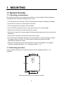
1
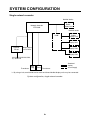
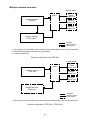
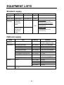
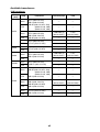
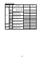
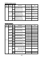
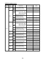
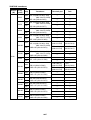
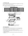
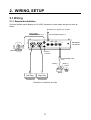
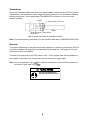
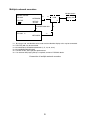
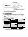
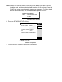
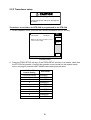
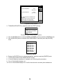
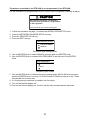
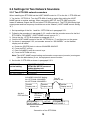
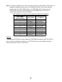
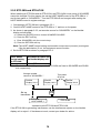
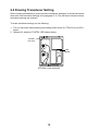
Back
NETWORK SOUNDER
ETR-30N
SAFETY INSTRUCTIONS
WARNING
WARNING
ELECTRICAL SHOCK HAZARD
Install the transducer tank according
to the installation instructions.
Do not open the equipment
unless totally familiar with
electrical circuits and
service manual.
Failure to install the tank correctly may
result in water leakage and damage to
the ship's hull.
Only qualified personnel
should work inside the
equipment.
Turn off the power at the switchboard
before beginning the installation.
Fire or electrical shock can result if the
power is left on.
Do not install the equipment where it
may get wet from rain or water splash.
Water in the equipment can result in fire,
electrical shock or damage to the equipment.
Be sure no water leaks in at the transducer mounting location.
Water leakage can sink the vessel. Also,
confirm that the transducer will not loosen
by ship's vibration. The installer of the
equipment is solely responsible for the
proper installation of the equipment.
FURUNO will assume no responsibility for
any damage associated with improper
installation.
Be sure that the power supply is
compatible with the voltage rating of
the equipment.
Connection of an incorrect power supply
can cause fire or damage the equipment.
Do not diassemble or modify the
equipment.
Electrical shock, damage to the equipment
or injury may result.
i
CAUTION
CAUTION
Ground the equipment to
prevent mutual interference.
The transducer cable must be handled
carefully, following the guidelines
below.
• Keep fuels and oils away from the
cable.
• Locate the cable where it will not be
damaged.
• The cable sheath is made of chlorophrene or polychloride vinyl, which
is easily damaged by plastic solvents
such as toulene. Locate the cable
well away from plastic solvents.
Observe the following compass safe
distances to prevent interference to a
magnetic compass:
Standard
compass
ETR-30N
1.7 m
Steering
compass
1.1 m
Do not allow warm water or any liquid
other than seawater or freshwater to
contact the transducer.
Use the correct fuse.
Use of a wrong fuse can cause serious
damage to the equipment.
Damage to the transducer may result.
Be sure to enter transducer model
correctly.
Do not install the transducer where
noise or air bubbles is present.
Incorrect setting may damage the
transducer.
Performance will be affected.
Do not enter transducer type manually
if the transducer type is programmed
into the equipment.
Damage to the transducer may result.
WARNING LABEL
A warning label is attached to the equipment. Do not remove the label. If the
label is missing or illegible, contact
a FURUNO agent or dealer about
replacement.
WARNING
To avoid electrical shock, do not
remove cover. No user-serviceable
parts inside.
ii
Name: Warning Label (1)
Type: 86-003-1011-1
Code No.: 100-236-231
TABLE OF CONTENTS
SYSTEM CONFIGURATION................................................................................ iv
EQUIPMENT LISTS ............................................................................................. vi
1. MOUNTING ...................................................................................................... 1
1.1 Network Sounder............................................................................................................. 1
1.2 Transducer...................................................................................................................... 2
2. WIRING, SETUP ............................................................................................... 3
2.1 Wiring.............................................................................................................................. 3
2.2 Settings for Single Network Sounder............................................................................... 6
2.3 Settings for Two Network Sounders............................................................................... 12
2.4 Erasing Transducer Setting ........................................................................................... 15
3. OPERATION, MAINTENANCE ...................................................................... 16
3.1 Controls......................................................................................................................... 16
3.2 Additions to NavNet Series Operator’s Manual.............................................................. 17
3.3 Replacing Fuses ........................................................................................................... 18
3.4 All Clear......................................................................................................................... 19
APPENDIX NEW BLT TRANSDUCERS ........................................................ AP-1
SPECIFICATIONS........................................................................................... SP-1
PACKING LIST ................................................................................................. A-1
OUTLINE DRAWINGS ...................................................................................... D-1
INTERCONNECTION DIAGRAM ......................................................................S-1
iii
SYSTEM CONFIGURATION
Single network sounder
NavNet Series
NavNet
Radar
Display Unit
Network Sounder
ETR-30N
NavNet Series
HUB*
NavNet
Radar
Display Unit
NavNet
Display Unit
Rectifier
PR-62
NavNet
Display Unit
Ship’s Mains
12-24 VDC
NavNet
Display Unit
100/110/115/220/230 VAC,
1φ, 50/60 Hz
Transducer
High
Freq.
Low
Freq.
Transducer
: Standard
: Option
: Local Supply
* = By using a hub, one NavNet series radar and three NavNet display units may be connected.
System configuration, single network sounder
iv
Multiple network sounders
NavNet Series
HUB*1
Network Sounder
ETR-30N
NavNet
Radar
Display Unit
NavNet
Display Unit
NavNet
Display Unit
*3
Network Sounder
ETR-6/10N*2
: Standard
: Optional Supply
: Local Supply
*1 = By using a hub, one NavNet series radar and two NavNet display units may be connected.
*2 = Maximum two network sounders may be installed.
*3 = Connect to NET KP.
System configuration, two ETR-30N
NavNet Series
HUB*
Network Sounder
ETR-30N
NavNet
Radar
Display Unit
NavNet
Display Unit
NavNet
Display Unit
Network Sounder
ETR-6/10N
: Standard
: Optional Supply
: Local Supply
* = By using a hub, one NavNet series radar and two NavNet display units may be connected.
System configuration, ETR-30N + ETR-6/10N
v
EQUIPMENT LISTS
Standard supply
Name
Network
Sounder
Spare Parts*
Installation
Materials*
Type
ETR-30N
SP02-04601
CP02-07100
(w/NavNet
connection
cable)
Code No.
—
Qty
002-180-150
—
1 set
Remarks
1
1 set
CP02-07110
—
(No NavNet
connection
cable)
* = See packing list at end of manual.
• Power Cable
MJ-A3SPF0013-035
• NavNet connection cable
MJ-A6SPF0014-050 (5 m)
• CP02-07101
• Power Cable
MJ-A3SPF0013-035
• CP02-07101
Optional supply
Name
Type
Code No.
Remarks
Piggyback
Mount Kit
OP02-84
002-186-170
For mounting two network
sounders piggyback style
Cable Assy.
MJ-A6SPF0014-010
000-144-421
6P-6P, 1 m, For NavNet
MJ-A6SPF0014-050
000-144-422
6P-6P, 5 m, For NavNet
MJ-A6SPF0014-100
000-144-423
6P-6P, 10 m, For NavNet
MJ-A6SPF0014-200
000-144-424
6P-6P, 20 m, For NavNet
MJ-A6SPF0014-300
000-144-425
6P-6P, 30 m, For NavNet
MJ-A6SRMD/TM11AP8-005
000-144-463
For HUB
NCS255AD-254P-L500
000-142-518
For connection of
combination transducers
MJ-A7SPF0002-050
000-127-656
For connecting ETRs
PR-62
000-013-484
100 VAC
000-013-485
110 VAC
000-013-486
220 VAC
000-013-487
230 VAC
Rectifier
Transducer
See the next several pages for transducer and recommended thru-hull pipe
and tank.
vi
Available transducers
1kW transducer
Freq.
(kHz)
Ship
Steel
FRP
28/50
Steel
FRP
Steel
FRP
28/68
Steel
FRP
Steel
28/88
FRP
28/200
Steel
FRP
Steel
FRP
50/88
Steel
FRP
Steel
FRP
Transducer
Thru-hull pipe
Tank
—
—
—
—
TWB-6000 (2)
(000-015-207)
T-656
(000-015-982)
—
—
28F-8 (000-015-003)
50F-8G (000-015-066)
—
—
—
—
28F-8 (000-015-003)
68F-8H (000-015-067)
—
—
—
—
TWB-6000 (2)
(000-015-207)
T-657
(000-015-983)
—
—
—
—
—
—
—
—
—
—
TWB-6000 (2)
(000-015-207)
T-658
(000-015-984)
—
—
—
—
—
—
28F-8 (000-015-003)
50B-6 (000-015-042)
50B-6B (000-015-043, 15M)
(000-015-018, 30M)
(000-015-255, 40M)
28F-8 (000-015-003)
50B-9 (000-138-574)
50B-9B (000-015-065)
28F-8 (000-015-003)
88B-8 (000-015-024)
28F-8 (000-015-003)
200B-5S (000-015-029)
50B-6 (000-015-042)
50B-6B (000-015-043, 15M)
(000-015-018, 30M)
(000-015-255, 40M)
88B-8 (000-015-024)
50B-9 (000-138-574)
50B-9B (000-015-065)
88B-8 (000-015-024)
50F-8G (000-015-066)
88B-8 (000-015-024)
vii
1kW transducer (con’t)
Freq.
(kHz)
Ship
Steel
FRP
Steel
FRP
50/200
Steel
FRP
Steel
Transducer
Thru-hull pipe
Tank
—
—
—
—
—
—
—
—
—
—
—
—
—
—
—
—
—
—
—
—
68F-8H (000-015-067)
200B-5S (000-015-029)
—
—
—
—
88B-8 (000-015-024)
200B-5S (000-015-029)
—
—
—
—
50B-6 (000-015-042)
50B-6B (000-015-043, 15M)
(000-015-018, 30M)
(000-015-255, 40M)
200B-5S (000-015-029)
50B-9 (000-138-574)
50B-9B (000-015-065)
200B-5S (000-015-029)
50F-8G (000-015-066)
200B-5S (000-015-029)
50/200-1T (000-015-170)
FRP
Steel
50/200-1ST (000-015-110)
FRP
Steel
68/200
FRP
88/200
Steel
FRP
viii
2kW transducer
Freq.
(kHz)
Ship
Steel
28/50
FRP
Steel
28/68
FRP
Steel
28/88
FRP
Steel
28/200
FRP
Transducer
Thru-hull pipe
TFB-7000 (2)
(000-015-209)
28F-18 (000-015-004, 15M)
(000-138-573, 30M)
50B-12 (000-015-020)
28F-18 (000-015-004, 15M)
(000-138-573, 30M)
68F-30H (000-015-073)
28F-18 (000-015-004, 15M)
(000-138-573, 30M)
88B-10 (000-015-025)
28F-18 (000-015-004, 15M)
(000-138-573, 30M)
200B-8 (000-015-030)
200B-8B (000-015-032)
200B-8N (000-015-045)
Steel
50B-12 (000-015-020)
88B-10 (000-015-025)
50/88
FRP
Steel
FRP
50B-12 (000-015-020)
200B-8 (000-015-030)
200B-8B (000-015-032)
200B-8N (000-015-045)
Steel
50BL-12 (000-015-246)
200B-8B (000-015-032)
FRP
Steel
68/200
FRP
Steel
88/200
FRP
68F-30H (000-015-073)
200B-8 (000-015-030)
200B-8B (000-015-032)
200B-8N (000-015-045)
88B-10 (000-015-025)
200B-8 (000-015-030)
200B-8B (000-015-032)
200B-8N (000-015-045)
ix
T-634
(000-015-810)
—
—
—
—
TRB-1100 (2)
(000-015-218)
T-634-F
(000-015-811)
TFB-7000 (2)
(000-015-209)
T-636
(000-015-813)
TRB-1100 (2)
(000-015-218)
T-636-F
(000-015-814)
TFB-7000 (2)
(000-015-209)
T-638
(000-015-818)
TRB-1100 (2)
(000-015-218)
T-638-F
(000-015-819)
TFB-7000 (2)
(000-015-209)
T-643
(000-015-821)
TRB-1100 (2)
(000-015-218)
T-643-F
(000-015-822)
TFB-7000 (2)
(000-015-209)
T-645
(000-015-826)
—
50/200
Tank
—
TWB-6000 (2)
(000-015-207)
T-693
(000-015-044)
TRB-1100 (2)
(000-015-218)
T-693-F
(000-015-241)
TFB-7000 (2)
(000-015-209)
T-647
(000-015-831)
TRB-1100 (2)
(000-015-218)
T-647-F
(000-015-832)
TFB-7000 (2)
(000-015-209)
T-649
(000-015-833)
TRB-1100 (2)
(000-015-218)
T-649-F
(000-015-834)
3kW transducer
Freq.
(kHz)
28/45
Ship
Steel
FRP
Transducer
28F-24H (000-015-075)
45F-12H (000-015-076)
—
—
TRB-1100 (2)
(000-015-218)
T-681-F
(000-015-850)
Steel
TWB-6000 (2)
(000-015-207)
T-696
(000-015-048)
TRB-1100 (2)
(000-015-218)
T-696-F
(000-015-244)
28F-24H (000-015-075)
50BL-24H (000-015-247)
FRP
Steel
FRP
28F-24H (000-015-075)
68F-30H (000-015-073)
—
—
—
—
TFB-7000 (2)
(000-015-209)
T-682
(000-015-851)
TRB-1100 (2)
(000-015-218)
T-682-F
(000-015-852)
TFB-7000 (2)
(000-015-209)
T-683
(000-015-853)
FRP
TRB-1100 (2)
(000-015-218)
T-683-F
(000-015-854)
Steel
TFB-7000 (2)
(000-015-209)
T-683
(000-015-853)
TRB-1100 (2)
(000-015-218)
T-683-F
(000-015-854)
Steel
28/88
FRP
Steel
28/150
28/200
28F-24H (000-015-075)
88F-126H (000-015-068)
28F-24H (000-015-075)
150B-12H (000-015-074)
28F-24H (000-015-075)
200B-12H (000-015-069)
FRP
Steel
FRP
Steel
FRP
45/200
—
FRP
28/50
45/150
—
T-681
(000-015-849)
28F-24H (000-015-075)
50F-24H (000-138-582)
45/88
Tank
TFB-7000 (2)
(000-015-209)
Steel
28/68
Thru-hull pipe
Steel
FRP
45F-12H (000-015-076)
88F-126H (000-015-068)
45F-12H (000-015-076)
150B-12H (000-015-074)
45F-12H (000-015-076)
200B-12H (000-015-069)
—
—
—
—
—
—
—
—
—
—
—
—
TFB-7000 (2)
(000-015-209)
T-682
(000-015-851)
FRP
TRB-1100 (2)
(000-015-218)
T-682-F
(000-015-852)
Steel
TWB-6000 (2)
(000-015-207)
T-697
(000-015-239)
TRB-1100 (2)
(000-015-218)
T-697-F
(000-015-245)
Steel
50F-24H (000-138-582)
88F-126H (000-015-068)
50/88
50BL-24H (000-015-247)
88F-126H (000-015-068)
FRP
x
3kW transducer (con’t)
Freq.
(kHz)
Ship
Transducer
Tank
TFB-7000 (2)
(000-015-209)
TRB-1100 (2)
(000-015-218)
T-683
(000-015-853)
T-683-F
(000-015-854)
TFB-7000 (2)
(000-015-209)
T-683
(000-015-853)
FRP
TRB-1100 (2)
(000-015-218)
T-683-F
(000-015-854)
Steel
TWB-6000 (2)
(000-015-207)
T-695
(000-015-047)
FRP
TRB-1100 (2)
(000-015-218)
T-695-F
(000-015-243)
Steel
TFB-7000 (2)
(000-015-209)
T-646
(000-015-829)
TRB-1100 (2)
(000-015-218)
T-646-F
(000-015-830)
TFB-7000 (2)
(000-015-209)
T-646
(000-015-829)
TRB-1100 (2)
(000-015-218)
T-646-F
(000-015-830)
Steel
50/150
FRP
Steel
50F-24H (000-138-582)
150B-12H (000-015-074)
50F-24H (000-138-582)
200B-12H (000-015-069)
50/200
68/150
FRP
50BL-24H (000-015-247)
200B-12H (000-015-069)
68F-30H (000-015-073)
150B-12H (000-015-074)
Steel
68F-30H (000-015-073)
200B-12H (000-015-069)
68/200
FRP
88/150
Thru-hull pipe
Steel
FRP
88F-126H (000-015-068)
150B-12H (000-015-074)
Steel
88F-126H (000-015-068)
200B-12H (000-015-069)
88/200
FRP
—
—
—
—
TFB-7000 (2)
(000-015-209)
T-685
(000-015-855)
TRB-1100 (2)
(000-015-218)
T-685-F
(000-015-856)
xi
1kW/2kW transducer
Output
(W)
Freq.
(kHz)
28/50
Ship
Steel
FRP
28/68
Steel
FRP
28/88
Steel
FRP
Steel
28/200
FRP
45/88
Steel
FRP
Steel
45/200
FRP
Steel
1 k/2 k
FRP
50/88
Steel
FRP
Transducer
Thru-hull pipe
Tank
28F-8 (000-015-003)
50B-12 (000-015-020)
—
—
—
—
28F-8 (000-015-003)
68F-30H (000-015-073)
—
—
—
—
28F-8 (000-015-003)
88B-10 (000-015-025)
—
—
—
—
28F-8 (000-015-003)
200B-8 (000-015-030)
200B-8B (000-015-032)
200B-8N (000-015-045)
—
45F-3H
88B-10 (000-015-025)
—
—
—
—
45F-3H
200B-8 (000-015-030)
200B-8B (000-015-032)
200B-8N (000-015-045)
50B-6 (000-015-042)
50B-6B (000-015-043, 15M)
(000-015-018, 30M)
(000-015-255, 40M)
88B-10 (000-015-025)
50B-9 (000-138-574)
50B-9B (000-015-065)
88B-10 (000-015-025)
—
—
—
—
—
—
—
—
—
—
—
—
50F-8G (000-015-066)
88B-10 (000-015-025)
FRP
Steel
FRP
50/200
Steel
FRP
T-657
(000-015-983)
—
Steel
50/88
TWB-6000 (2)
(000-015-207)
50B-6 (000-015-042)
50B-6B (000-015-043, 15M)
(000-015-018, 30M)
(000-015-255, 40M)
200B-8 (000-015-030)
200B-8B (000-015-032)
200B-8N (000-015-045)
50B-9 (000-138-574)
50B-9B (000-015-065)
200B-8 (000-015-030)
200B-8B (000-015-032)
200B-8N (000-015-045)
xii
TFB-7000 (2)
(000-015-209)
T-636
(000-015-813)
TRB-1100 (2)
(000-015-218)
T-636-F
(000-015-814)
—
—
—
—
TWB-6000 (2)
(000-015-207)
—
T-658
(000-015-984)
—
1kW/2kW transducer (con’t)
Output
(W)
Freq.
(kHz)
Ship
Steel
50/200
FRP
Steel
68/200
FRP
Steel
88/200
FRP
Transducer
50F-8G (000-015-066)
200B-8 (000-015-030)
200B-8B (000-015-032)
200B-8N (000-015-045)
68F-8H (000-015-067)
200B-8 (000-015-030)
200B-8B (000-015-032)
200B-8N (000-015-045)
88B-8 (000-015-024)
200B-8 (000-015-030)
200B-8B (000-015-032)
200B-8N (000-015-045)
Thru-hull pipe
Tank
TFB-7000 (2)
(000-015-209)
T-638
(000-015-818)
TRB-1100 (2)
(000-015-218)
T-638-F
(000-015-819)
—
—
—
—
TWB-6000 (2)
(000-015-207)
T-659
(000-015-985)
—
—
Thru-hull pipe
Tank
28F-8 (000-015-003)
45F-12H (000-015-076)
—
—
—
—
28F-8 (000-015-003)
50F-24H (000-138-582)
—
—
—
—
28F-8 (000-015-003)
68F-30H (000-015-073)
—
—
—
—
28F-8 (000-015-003)
88F-126H (000-015-068)
—
—
—
—
28F-8 (000-015-003)
100B-10R (000-027-438)
—
—
—
—
28F-8 (000-015-003)
150B-12H (000-015-074)
—
—
—
—
28F-8 (000-015-003)
200B-12H (000-015-069)
—
—
—
—
—
—
—
—
—
—
—
—
1kW/3kW transducer
Output
(W)
Freq.
(kHz)
28/45
Ship
Steel
FRP
28/50
Steel
FRP
28/68
Steel
FRP
28/88
Steel
FRP
28/107
Steel
FRP
1 k/3 k
28/150
Steel
FRP
28/200
Steel
FRP
Steel
50/88
FRP
Steel
FRP
Transducer
50B-6 (000-015-042)
50B-6B (000-015-043, 15M)
(000-015-018, 30M)
(000-015-255, 40M)
88F-126H (000-015-068)
50B-9B (000-015-065)
88F-126H (000-015-068)
xiii
1kW/3kW transducer (con’t)
Output
(W)
Freq.
(kHz)
50/88
Ship
Steel
FRP
Steel
FRP
50/150
Steel
FRP
Steel
FRP
Steel
50/200
FRP
Steel
1 k/3 k
FRP
50/200
Steel
FRP
68/107
Steel
FRP
68/150
Steel
FRP
68/200
Steel
FRP
88/150
Steel
FRP
50/200
Steel
FRP
68/150
Steel
FRP
Transducer
Thru-hull pipe
Tank
50F-8G (000-015-066)
88F-126H (000-015-068)
—
—
—
—
50B-6 (000-015-042)
50B-6B (000-015-043, 15M)
(000-015-018, 30M)
(000-015-255, 40M)
150B-12H (000-015-074)
—
—
—
—
50B-9 (000-138-574)
50B-9B (000-015-065)
150B-12H (000-015-074)
—
—
—
—
50F-8G (000-015-066)
150B-12H (000-015-074)
—
—
—
—
—
—
—
—
50B-9 (000-138-574)
50B-9B (000-015-065)
200B-12H (000-015-069)
—
—
—
—
50F-8G (000-015-066)
200B-12H (000-015-069)
—
—
—
—
68F-8H (000-015-067)
100B-10R (000-027-438)
—
—
—
—
68F-8H (000-015-067)
150B-12H (000-015-074)
—
—
—
—
68F-8H (000-015-067)
200B-12H (000-015-069)
—
—
—
—
88B-8 (000-015-024)
150B-12H (000-015-074)
—
—
—
—
50F-8G (000-015-066)
200B-12H (000-015-069)
—
—
—
—
68F-8H (000-015-067)
150B-12H (000-015-074)
—
—
—
—
50B-6 (000-015-042)
50B-6B (000-015-043, 15M)
(000-015-018, 30M)
(000-015-255, 40M)
200B-12H (000-015-069)
xiv
1kW/3kW transducer (con’t)
Output
(W)
Freq.
(kHz)
68/200
Ship
Steel
FRP
1 k/3 k
88/150
Steel
FRP
88/200
Steel
FRP
Transducer
Thru-hull pipe
Tank
68F-8H (000-015-067)
200B-12H (000-015-069)
—
—
—
—
88B-8 (000-015-024)
150B-12H (000-015-074)
—
—
—
—
88B-8 (000-015-024)
200B-12H (000-015-069)
—
—
—
—
xv
2kW/3kW transducer
Output
(W)
Freq.
(kHz)
Ship
Transducer
Thru-hull pipe
Tank
Steel
28F-18 (000-015-004, 15M)
(000-138-573, 30M)
45F-12H (000-015-076)
—
—
—
—
28F-18 (000-015-004, 15M)
(000-138-573, 30M)
50F-24H (000-015-077)
—
—
—
—
28F-18 (000-015-004, 15M)
(000-138-573, 30M)
68F-30H (000-015-073)
—
—
—
—
28F-18 (000-015-004, 15M)
(000-138-573, 30M)
88F-126H (000-015-068)
—
—
—
—
TFB-7000 (2)
(000-015-209)
T-637
(000-015-816)
TRB-1100 (2)
(000-015-218)
T-637-F
(000-015-817)
28F-18 (000-015-004, 15M)
(000-138-573, 30M)
200B-12H (000-015-069)
—
—
—
—
50B-12 (000-015-020)
88F-126H (000-015-068)
—
—
—
—
TFB-7000 (2)
(000-015-209)
T-644
(000-015-824)
TRB-1100 (2)
(000-015-218)
T-644-F
(000-015-825)
50B-12 (000-015-020)
200B-12H (000-015-069)
—
—
—
—
68F-30H (000-015-073)
150B-12H (000-015-074)
—
—
—
—
68F-30H (000-015-073)
200B-12H (000-015-069)
—
—
—
—
88B-10 (000-015-025)
150B-12H (000-015-074)
—
—
—
—
88B-10 (000-015-025)
200B-12H (000-015-069)
—
—
—
—
28/45
FRP
Steel
28/50
FRP
Steel
28/68
FRP
Steel
28/88
FRP
Steel
28/150
FRP
Steel
28/200
FRP
2k/3k
50/88
Steel
FRP
Steel
50/150
FRP
50/200
Steel
FRP
68/150
Steel
FRP
68/200
Steel
FRP
88/150
Steel
FRP
88/200
Steel
FRP
28F-18 (000-015-004, 15M)
(000-138-573, 30M)
150B-12H (000-015-074)
50B-12 (000-015-020)
150B-12H (000-015-074)
xvi
3kW/2kW transducer (con’t)
Output
(W)
Freq.
(kHz)
28/50
Ship
Steel
FRP
28/68
Steel
FRP
28/88
Steel
FRP
Steel
28/200
FRP
45/88
Steel
FRP
Steel
3k/2k
45/200
FRP
50/88
Steel
FRP
Steel
50/200
FRP
Steel
68/200
FRP
Steel
88/200
FRP
Transducer
Thru-hull pipe
Tank
28F-24H (000-015-075)
50B-12 (000-015-020)
—
—
—
—
28F-24H (000-015-075)
68F-30H (000-015-073)
—
—
—
—
28F-24H (000-015-075)
88B-10 (000-015-025)
—
—
—
—
—
—
—
—
—
—
—
—
—
—
—
—
—
—
—
—
—
—
—
—
28F-24H (000-015-075)
200B-8 (000-015-030)
200B-8B (000-015-032)
200B-8N (000-015-045)
45F-12H (000-015-076)
88B-10 (000-015-025)
45F-12H (000-015-076)
200B-8 (000-015-030)
200B-8B (000-015-032)
200B-8N (000-015-045)
50F-24H (000-015-077)
88B-10 (000-015-025)
50F-24H (000-015-077)
200B-8 (000-015-030)
200B-8B (000-015-032)
200B-8N (000-015-045)
68F-30H (000-015-073)
200B-8 (000-015-030)
200B-8B (000-015-032)
200B-8N (000-015-045)
88F-126H (000-015-068)
200B-8 (000-015-030)
200B-8B (000-015-032)
200B-8N (000-015-045)
xvii
TFB-7000 (2)
(000-015-209)
TRB-1100 (2)
(000-015-218)
T-647
(000-015-831)
T-647-F
(000-015-832)
—
—
—
—
1. MOUNTING
1.1 Network Sounder
1.1.1 Mounting considerations
The network sounder can be installed on the deck or on the bulkhead. When selecting a
mounting location, keep the following points in mind:
• The temperature and humidity of the mounting location should be moderate and stable.
• Locate the unit away from exhaust pipes and vents.
• The mounting location should be well ventilated.
• Do not install the equipment where it may get wet from rain or water splash.
• Mount the unit where shock and vibration are minimal.
• Keep the unit away from electromagnetic field-generating equipment such as motors and
generators.
• Leave slack in cables for maintenance and servicing ease.
• For mounting on a bulkhead, be sure the mounting location is strong enough to support
the weight of the unit (5.6 kg, 12.3 lbs) under the continued vibration normally
experienced onboard the vessel.
• Observe the following compass safe distances to prevent disturbance to a magnetic
compass: standard compass, 1.7 m, steering compass, 1.1 m.
1.1.2 Mounting procedure
Fix the network sounder to the mounting location with four tapping screws (5 × 25,
supplied).
404 ±1
200 ±0.5
200 ±0.5
Mounting dimensions for the network sounder
1
1.1.3 Stacking units
You may stack two network sounders by using the optional piggyback mount kit (Type
OP02-84, Code No. 002-186-170) as below.
Note: Change the tap setting on the lower unit before installing the upper unit. See
paragraph 2.2 for how to change tap setting.
Contents of piggyback mount kit
Name
Type
Code No.
Qty
Jointing Fixture (LWR)
02-142-1131
100-300-211
1
Jointing Fixture (UPR)
02-142-1132
100-300-221
1
Hexagon Head Bolt B
M5 x 12
000-803-147
2
Pan Head Screw B
M4 x 8
000-881-445
15
#
#
#
#
#
FURUNO
NETWORK SOUNDER ETR-30N
#
HOST NAME
4 5
6
3
7
2
8
1
0 9
DEFAULT
Remarks
Remove mounting feet.
#
TX/STBY POWER
I
ON
Jointing Fixture (UPR)
O OFF
#
Pan Head Screw B
SIDE VIEW
Jointing Fixture (LWR)
Hexagon
Head
Bolt B
#
#
#
#
#
#
#
FURUNO
NETWORK SOUNDER ETR-30N
HOST NAME
4 5
6
3
7
2
8
1
0 9
DEFAULT
TX/STBY POWER
I
ON
O OFF
# = Screw location (15)
How to assemble the piggyback mount kit
1.2 Transducer
The performance of this sounder is directly related to the mounting location of the
transducer. When selecting a mounting location keep in mind the following points:
• Select a location not influenced by air bubbles and engine noise.
• As a general rule the position between 1/3 and 1/2 of ship’s length from the bow is
usually a good location.
• The face of the transducer must be facing the sea bottom under normal cruising
conditions.
2
2. WIRING, SETUP
2.1 Wiring
2.1.1 Standard installation
Connect NavNet series display unit or HUB, transducer, power cable and ground wire as
below.
NavNet Series display unit or HUB
Ground Wire
KIV 2.0SQ, black, 2 m
MJ-A6SPF0014-050, 5 m
TRANSDUCER
L
NETWORK
H
NET KP
OUT/IN
OUT/IN
12-24VDC
+1
NETWORK
SOUNDER
3 GND
2
-
Ground
Ground
Terminal
MJ-A3SPF0013-035,
3.5m
Black (-)
White (+)
Shield
Battery
Low Freq.
High Freq.
Transducer
Transducer
Connection of network sounder
3
Transducer
Route the transducer cable well away from power cables, televisions and CRTs to prevent
interference to the network sounder. Attach the NCS connector to the transducer cable as
below and connect it to the appropriate TRANSDUCER connector on the front of the
network sounder.
Shield
Shield Foam 71TS-10-1
Cable
NCS Connector Cable Clamp
NCS-254-P
How to attach connector to transducer cable
Note: For dual-frequency transducer, use the optional cable assy. NCS255AD-254P-L500.
Ground
To prevent interference to the picture and radio equipment, connect a ground wire (KIV 2.0
sq, black) between the ground terminal and ship’s grounding bus. The length of the wire
should be as short as possible.
To obtain a good ground on an FRP vessel, a 20 × 30 cm copper plate can be welded on
the outside of the ship’s hull. Connect the ground wire to the copper plate.
Note: Use a "closed-type" lug (
not use an "open-type" lug (
) to make the connection at the network sounder. Do
).
CAUTION
Ground the equipment to
prevent mutual interference.
4
Multiple network sounders
NavNet Series
Network Sounder
ETR-30N
*4
*3
NavNet
Display Unit
HUB
NETWORK
EXT KP
*6
*1
NET KP
OUT/IN
MJ-A7SPF0002-050
*5
Network Sounder NET KP OUT/IN
ETR-30N *2
NETWORK
*4
*2
*1 = By using a hub, one NavNet series radar and two NavNet display units may be connected.
*2 = Two ETR-30N may be connected.
*3 = MJ-A6SPF0014-010/050/100/200/300 (1, 5, 10, 20, 30 m)
*4 = MJ-A6SRMD/TM11AP8-005
*5 = Connect to NET KP to get best performance.
*6 = If an external KP (Keying Pulse) is required, contact a FURUNO dealer.
Connection of multiple network sounders
5
2.2 Settings for Single Network Sounder
WARNING
ELECTRICAL SHOCK HAZARD
Do not open the equipment.
Only qualified personnel
should work inside the
equipment.
2.2.1 Internal settings
Set the tap inside the network sounder to match transducer output power.
1. Disconnect the power cable from the network sounder.
2. Remove the cover of the network sounder.
.....
ABCDE ABCDE
J2
TAP
H
J9
.....
TAP
L
Network sounder ETR-30N, top view, cover removed
3. Using a pincers, set jumper block of TAP H (High) referring to the transducer label on
the cover. Jot down the tap position. When the NavNet display unit is powered you can
confirm setting (see page 10).
Note 1: The transducer model recorded on the label is in the unit’s memory. Therefore,
you can set transducer type following “Transducer connected to the ETR-30N is
programmed in the ETR-30N” (page 9.)
Note 2: To connect other make of transducer contact your FURUNO dealer for details.
4. If a low frequency transducer is installed, set TAP L.
5. Close the cover and connect the power cable to the network sounder.
6. Confirm that the HOST NAME control is in the “0” position.
6
HOST NAME Control
Sets host name.
FURUNO
HOST NAME
4 5
6
3
7
2
8
1
0 9
DEFAULT
NETWORK SOUNDER ETR-30N
TX/STBY POWER
I
ON
O OFF
POWER switch
Turns power
On and off.
LED lamp
The lamp flashes when the NavNet display unit
is powered and communicating with the network
sounder.
ETR-30N
7. Turn on the ETR-30N and the NavNet display unit.
8. Confirm that the LED lamp flashes.
2.2.2 Sounder source setting
1. Press the [POWER/BRILL] key on the NavNet series unit while pressing and holding
down the [MENU] key. Release the [POWER/BRILL] key when you hear a beep.
2. Release the [MENU] key when the message “STARTING INSTALLATION MODE”
appears.
3. After the radar screen appears, press the [MENU] key.
4. Press the SYSTEM CONFIGURATION soft key.
5. Press the INSTALLATION SETUP soft key.
RADAR
MENU
SYSTEM
CONFIG
INSTALL
SETUP
RADAR DISPLAY SETUP
GENERAL SETUP
NETWORK SETUP
RADAR RANGE SETUP
NAV OPTION
RADAR SETUP
ARP SETUP
SYSTEM SETUP
NETWORK SOUNDER SETUP
FUNCTION KEY SETUP
INSTALLATION SETUP
NETWORK SETUP FOR AUX#
RETURN
SYSTEM CONFIGURATION
RETURN
Radar menu
System configuration menu
Install setup menu
# =Shown on Model 1833C only
How to access the installation setup menu (example: radar NavNet unit)
7
Note: The very first time the system is powered you are asked if you want to start the
simulation mode, which provides simulated operation of the equipment. Press the
[CLEAR] key to start normal operation to set up the transducer. For further details
about the simulation mode, see your NavNet series operator’s manual.
START
SIMULATION MODE?
YES ... PUSH ENTER KNOB
NO ... PUSH CLEAR KEY
TO SKIP.
Simulation mode window
6. Press the NETWORK SETUP soft key.
IP ADDRESS
HOST NAME
RADAR SOURCE
CHART SOURCE
172.031.092.001
RADAR________
RADAR________
______________
______________
______________
SOUNDER SOURCE SOUNDER
AUX*
WFAX
SUBNET MASK
255.255.000.000
GATEWAY ADDRESS 000.000.000.000
OFFSET PORT NUMBER
10000
NETWORK
SETUP
EDIT
RETURN
* = Model 1833C only.
Network setup menu
7. Confirm that the “SOUNDER SOURCE” is SOUNDER.
8
2.2.3 Transducer setup
CAUTION
Enter transducer setting correctly.
A wrong transducer setting can damage the
transducer.
Transducer connected to the ETR-30N is programmed in the ETR-30N
1. At the installation menu, press the NETWORK SOUNDER SETUP soft key.
IP ADDRESS
HOST NAME
172.031.092.001
SOUNDER____
SNDR
SETUP
EDIT
Note: Do not change IP address or host
name from this display.
FREQ
SETUP
RETURN
Sounder setup
2. Press the FREQ SETUP soft key. (If the FREQ SETUP soft key is not shown, check that
the ETR-30N is powered.) Confirm that sounder source (shown on the network setup
menu, see page 8) and the HOST NAME control setting are the same.
HOST NAME
Control Setting
Host Name
0 (Default Setting)
SOUNDER
1
SOUNDER1
2
SOUNDER2
3
SOUNDER3
4
SOUNDER4
5
SOUNDER5
6
SOUNDER6
7
SOUNDER7
8
SOUNDER8
9
SOUNDER9
9
TRANSDUCER SETUP
MANUAL
HIGH FREQUENCY
--kHz
(0kW TAP:-)
LOW FREQUENCY
--kHz
(0kW TAP:-)
TAP SETTINGS MUST BE MADE ON
ETR UNIT.
AFTER SETUP, DISPLAY MUST BE
TURNED OFF & ON TO ALLOW
NEW SETTINGS TO TAKE EFFECT.
SNDR
SETUP
EDIT
RETURN
Frequency setup screen
3. TRANSDUCER SETUP is selected; press the EDIT soft key.
TRANSDUCER SETUP
MODEL NUMBER
MANUAL
Transducer type setting method options
4. Use the [ENTER] knob to choose MODEL NUMBER and then push the [ENTER] knob.
5. Use the [ENTER] knob to choose HIGH FREQUENCY and then push the [ENTER]
knob.
HIGH FREQUENCY
28kHz 28F-8
28kHz 28F-18
28kHz 28F-24H
38kHz 38E-9-18S1
45kHz 45F-12H
50kHz 50B-6/6B
50kHz 50B-9/9B
50kHz 50F-8G
50kHz 50/200-1ST
50kHz 50/200-1T
Frequency options
6. Rotate the [ENTER] knob to choose transducer and then push the [ENTER] knob.
7. Confirm tap position at the SNDR SETUP screen.
8. If a low-frequency transducer is installed, set it following this procedure.
9. Turn off the NavNet display unit.
10. Turn on the NavNet display unit. Confirm that the echo sounder picture advances.
10
Transducer connected to the ETR-30N is not programmed in the ETR-30N
For the transducer not programmed in the ETR-30N, enter its frequency manually as below.
CAUTION
Do not enter transducer specifications
manually if the transducer is programmed
in the equipment.
The transducer may become damaged.
1.
2.
3.
4.
Follow the procedure on page 7 to shown the INSTALLATION SETUP menu.
Press the NETWORK SOUNDER SETUP soft key.
Press the FREQ SETUP soft key.
Press the EDIT soft key.
TRANSDUCER SETUP
MODEL NUMBER
MANUAL
Transducer type setting options
5. Use the [ENTER] knob to select MANUAL and then push the [ENTER] knob.
6. Use the [ENTER] knob to choose HIGH FREQUENCY and then push the [ENTER]
knob.
HIGH FREQUENCY
12.0kHz
Frequency input screen
7. Use the [ENTER] knob to choose frequency (setting range: 25 kHz-220 kHz) and then
push the [ENTER] knob. Currently, 12-24.8 kHz and 221-420 kHz cannot be set. These
frequencies are for future use.
8. If a low-frequency transducer is installed, set it similarly.
9. Turn off the NavNet display unit.
10. Turn on the Navnet display unit. Confirm that the echo sounder picture advances.
11
2.3 Settings for Two Network Sounders
2.3.1 Two ETR-30N network sounders
When installing two ETR-30N set the HOST NAME control to “0” for the No. 1 ETR-30N and
“1” for the No. 2 ETR-30 N. Turn the ETR-30N off and on again after setting the HOST
NAME control to register settings. When connecting NET KP, the ETR-30N having the
lowest IP address outputs the KP and other ETR-30N receives it. The ETR-30N having high
output power and low frequency should be set as the “Master” (HOST NAME control setting
“0”).
1. Set tap settings of the No. 1 and No. 2 ETR-30N as in paragraph 2.2.1.
2. Following the procedure in paragraph 2.2.2, confirm that the sounder source for the No.1
ETR-30N is “SOUNDER.” (HOST NAME control is set to “0.”)
3. Set up the No. 1 ETR-30 as shown in paragraph 2.2.3.
4. Set the HOST NAME control of the No. 2 ETR-30N to “1” and then turn on the power.
5. As shown in paragraph 2.2.2, set sounder source for “SOUNDER1” on the NavNet
display unit as below.
a) Rotate the [ENTER] knob to choose SOUNDER SOURCE.
b) Press the EDIT soft key.
c) Enter SOUNDER1 with the numeric keys.
d) Press the RETURN soft key.
Note: The HOST NAME control setting and sounder source name (numeric) must agree.
(See the table below.) If not, the equipment cannot function.
6. Set the No. 2 ETR-30N as shown in paragraph 2.2.3.
HOST NAME
control setting
No. 1 ETR-30N: 0
No. 2 ETR-30N: 1
SOUNDER SOURCE set on
NETWORK SETUP screen of
NavNet display unit
SOUNDER_
SOUNDER1
SOUNDER SOURCE Setting:
No.1 ETR-30N: SOUNDER
No.2 ETR-30N: SOUNDER1
NavNet
Display Unit 1
Set No.1
ETR-30N first.
Turn off
power to set.
NavNet
Display Unit 2
Set No.2
ETR-30N
second.
NavNet
Display Unit 3
HUB
NET KP
ETR-30N No.1
HOST NAME: 0
ETR-30N No. 2
HOST NAME: 1
Master side
Connection of two ETR-30Ns
12
Note: The same IP address cannot be used when installing two ETR-30N or ETR-6/10N. To
change IP address and host name, set a different number (1-9) for each network
sounder with the HOST NAME switch on the ETR-30N. Note however that the
ETR-6/10N’s host name and IP address are “SOUNDER” and “172.31.92.1,”
respectively, and they cannot be changed.
HOST NAME control setting and resulting host name and IP address
HOST NAME
Control Setting
Host Name
IP Address
0 (Default Setting)
SOUNDER
172.31.92.1
1
SOUNDER1
172.31.92.11
2
SOUNDER2
172.31.92.12
3
SOUNDER3
172.31.92.13
4
SOUNDER4
172.31.92.14
5
SOUNDER5
172.31.92.15
6
SOUNDER6
172.31.92.16
7
SOUNDER7
172.31.92.17
8
SOUNDER8
172.31.92.18
9
SOUNDER9
172.31.92.19
NET KP
If installing two ETR-30Ns, connect cable MJ-A7SPF0002-050 between NET KP OUT/IN
ports to prevent interference. Maximum two ETR-30N units may be installed; however,
there are two ports. One is for future use.
13
2.3.2 ETR-30N and ETR-6/10N
When installing an ETR-30N and an ETR-6/10N, the ETR-6/10N’s host name of SOUNDER
cannot be changed. For this reason, the set the HOST NAME control of the ETR-30N to “1”
and its host name to “SOUNDER1.” Turn the ETR-30N off and on again after setting the
HOST NAME control to register settings.
1. Set tappings of ETR-30N as in paragraph 2.2.1.
2. Set the HOST NAME control of the ETR-30N to “1” and turn on the power.
3. As shown in paragraph 2.2.2, set sounder source for “SOUNDER1” on the NavNet
display unit as below.
a) Rotate the [ENTER] knob to choose SOUNDER SOURCE.
b) Press the EDIT soft key.
c) Enter SOUNDER1 with the numeric keys.
d) Press the RETURN soft key.
Note: The HOST NAME control setting and sounder source name (numeric) must agree.
(See the table below.) If not, the equipment cannot function.
4. Set the ETR-30N as shown in paragraph 2.2.3.
HOST NAME
SOUNDER SOURCE set
control setting
on NavNet display unit
on ETR-30N
1
SOUNDER1
Note: The host name and frequency on the ETR-6/10N are fixed to SOUNDER and 50/200
kHz, respectively.
Change sounder
source to "SOUNDER1."
NavNet
Display Unit 1
Turn power
off to set.
NavNet
Display Unit 2
Set up
transducer.
NavNet
Display Unit 3
HUB
ETR-30N
HOST NAME: 1
ETR-6/10N
Installation with ETR-30N and ETR-6/10N
If the ETR-6/10N is generating interference, use the interference rejector on the NavNet
display unit to reject it. If that does not work, contact your dealer for advice.
14
2.4 Erasing Transducer Setting
When changing transducer(s), erase previous transducer setting(s) as shown below and
then enter new transducer settings as in paragraph 2.2. (The set cannot transmit unless
transducer settings are entered.)
To erase transducer settings, do the following:
1. Turn on the power while pressing and holding down switch S1 (TDCLR) on the CPU
board.
2. Release S1 when the TX/STBY LED flashes slowly.
TX/STBY
LED lamp
ETR-30N, cover removed
15
02P6307
S1
CPU
Board
3. OPERATION, MAINTENANCE
WARNING
ELECTRICAL SHOCK HAZARD
Do not open the equipment.
Only qualified personnel
should work inside the
equipment.
3.1 Controls
HOST NAME Control
Sets host name.
FURUNO
HOST NAME
4 5
6
3
7
2
8
1
0 9
DEFAULT
NETWORK SOUNDER ETR-30N
TX/STBY POWER
I
ON
O OFF
POWER switch
Turns power
on and off.
LED lamp
Flashing:
The NavNet display unit is powered and
communicating with the network sounder.
Lighting (after flashing three minutes):
The NavNet connection cable is
disconnected or damaged.
Network sounder ETR-30N
16
3.2 Additions to NavNet Series Operator’s Manual
Depending on the version number of your NavNet series operator’s manual, its echo
sounder descriptions may not match the screens you see. Please add the following
descriptions to your manual if they are not already present.
Choosing pulse repetition rate (PRR)
Pulse repetition rate can be changed to reduce second reflection echoes. Normally, the
highest rate (20) is used. When in shallow waters, second reflection echoes may appear
between surface and actual bottom echo. In this case lower the pulse repetition rate. If the
setting is too small, it may not be possible to search fish schools effectively. Select “20”
unless second reflection echoes appear on the display. The option “S” means the ship’s
speed dependent mode, where the PRR automatically changes with ship’s speed (requires
speed input).
1.
2.
3.
4.
5.
6.
Press the [MENU] key to open the menu.
Press the SOUNDER MENU soft key.
Select PRR LEVEL.
Press the EDIT soft key to open the setting window.
Use the trackball or cursor pad to select pulse repetition rate desired.
Press the ENTER soft key followed by the [MENU] key to close the menu.
Sounder system setup menu
Menu items for adjustment of STC and frequencies and selection of fishing objective have
been added to the SOUNDER SYSTEM SETUP menu. Press the [MENU] key, choose
SOUNDER SYSTEM SETUP menu and then press the NEXT PAGE soft key.
STC - HF
STC - LF
FREQ. ADJ. - HF
FREQ. ADJ. - LF
TARGET ECHO
00
00
+00.0
+00.0
NORMAL
SYSTEM
SETUP 2
EDIT
PREV
PAGE
Page 2 of sounder system setup menu
STC-HF, LF
Adjusts STC level for the high and low frequencies, and is useful for suppressing surface
noise. The setting range is 0-10; the higher the setting the greater the degree of
suppression. Setting 10 suppresses noise up to about several meters from own ship. Turn
off the STC when there is no noise on the screen, otherwise weak echoes may be missed.
17
FREQ. ADJ
Adjusts transmitting frequency to suppress interference when it cannot be suppressed with
the interference rejector alone.
TARGET ECHO
Sets fishing objective. Choose NORMAL for general fishing; SURFACE for detecting
surface fish. Pulse repetition rate for “SURFACE” is higher than “NORMAL.”
Transducer frequency
The ETR-30N offers various transducer frequencies. Therefore, the descriptions “50 kHz”
and “200 kHz” should read as “LF (Low Frequency)” and “HF (High Frequency),”
respectively.
3.3 Replacing Fuses
The ETR-30N has two fuses to protect against overcurrent: a 5A fuse in the snap-in fuse
holder in the power cable and a 7A fuse inside the network sounder. If a fuse blows, find the
cause before replacing it. If it blows again after replacement, contact a FURUNO agent or
dealer for advice. If the LED lamp is off and the fuse in the power cable is normal, the fuse
inside the network sounder may have blown. If this occurs, contact a FURUNO agent or
dealer.
NOTICE
Use the correct fuse.
Use of a wrong fuse can cause serious
damage to the equipment.
18
3.4 All Clear
When the sounder picture appears to be abnormal, execute the “all clear” function from the
ETR-30N to try to restore normal operation. All clear erases all transducer settings, so
reenter them referring to paragraph 2.2.
1. Turn off the ETR-30N.
2. Remove the cover.
3. Short between #5 and #6 of J9 on the CPU Board and then turn on the power.
CPU Board
02P6307
24 6
13 5
J9
ETR-30N, cover removed
4. After the TX/STBY LED flashes, turn off the power.
19
This page is intentionally left blank.
20
APPENDIX NEW BLT TRANSDUCERS
A new type BLT transducer (Bolt-clamp Langevin Transducer) has been developed for this
echo sounder. The BLT transducer has large bandwidth, good sound efficiency, compact
structure and is reinforced for protection against slamming.
Transducer, thru-hull pipe and tank list
Frequency
(kHz)
28/200
38/200
50/200
28/38
28/50
38/50
28/88
38/88
Transducer
28BL-6HR/200B-8B
38BL-9HR/200B-8B
50BL-12HR/200B-8B
28BL-12HR/38BL-15HR
28BL-12HR/50BL-24HR
38BL-15HR/50BL-24HR
28BL-12HR/88F-126H
38BL-15HR/88F-126H
Hull
Material
Tank
(Code No.)
Fasten inside
hull (Code No.)
Fasten outside
hull (Code No.)
Steel
T-693
(000-015-044)
TWB-6000 (2)
(000-015-207)
TFB-7000 (2)
(000-015-209)
FRP
T-693F
(000-015-241)
TRB-1100 (2)
(000-015-219)
-
Steel
T-693
(000-015-044)
TWB-6000 (2)
(000-015-207)
TFB-7000 (2)
(000-015-209)
FRP
T-693F
(000-015-241)
TRB-1100 (2)
(000-015-219)
-
Steel
T-693
(000-015-044)
TWB-6000 (2)
(000-015-207)
TFB-7000 (2)
(000-015-209)
FRP
T-693F
(000-015-241)
TRB-1100 (2)
(000-015-219)
-
Steel
T-681
(000-015-849)
TWB-6000 (2)
(000-015-207)
TFB-7000 (2)
(000-015-209)
FRP
T-681F
(000-015-850)
TRB-1100 (2)
(000-015-219)
-
Steel
T-681
(000-015-849)
TWB-6000 (2)
(000-015-207)
TFB-7000 (2)
(000-015-209)
FRP
T-681F
(000-015-850)
TRB-1100 (2)
(000-015-219)
-
Steel
T-681
(000-015-849)
TWB-6000 (2)
(000-015-207)
TFB-7000 (2)
(000-015-209)
FRP
T-681F
(000-015-850)
TRB-1100 (2)
(000-015-219)
-
Steel
T-682
(000-015-851)
TWB-6000 (2)
(000-015-207)
TFB-7000 (2)
(000-015-209)
FRP
T-682F
(000-015-852)
TRB-1100 (2)
(000-015-219)
-
Steel
T-682
(000-015-851)
TWB-6000 (2)
(000-015-207)
TFB-7000 (2)
(000-015-209)
FRP
T-682F
(000-015-852)
TRB-1100 (2)
(000-015-219)
-
AP-1
50/88
50BL-24HR/88-126H
28/200
38/200
50/200
28/150
38/150
38/150
28BL-12HR/200B-12H
38BL-15HR/200B-12H
50BL-24HR/200B-12H
28BL-12HR/150B-12H
38BL-15HR/150-12H
50BL-24HR/156-12H
Steel
T-682
(000-015-851)
TWB-6000 (2)
(000-015-207)
TFB-7000 (2)
(000-015-209)
FRP
T-682F
(000-015-852)
TRB-1100 (2)
(000-015-219)
-
Steel
T-683
(000-015-853)
TWB-6000 (2)
(000-015-207)
TFB-7000 (2)
(000-015-209)
FRP
T-683F
(000-015-854)
TRB-1100 (2)
(000-015-219)
-
Steel
T-683
(000-015-853)
TWB-6000 (2)
(000-015-207)
TFB-7000 (2)
(000-015-209)
FRP
T-683F
(000-015-854)
TRB-1100 (2)
(000-015-219)
-
Steel
T-683
(000-015-853)
TWB-6000 (2)
(000-015-207)
TFB-7000 (2)
(000-015-209)
FRP
T-683F
(000-015-854)
TRB-1100 (2)
(000-015-219)
-
Steel
T-683
(000-015-853)
TWB-6000 (2)
(000-015-207)
TFB-7000 (2)
(000-015-209)
FRP
T-683F
(000-015-854)
TRB-1100 (2)
(000-015-219)
-
Steel
T-683
(000-015-853)
TWB-6000 (2)
(000-015-207)
TFB-7000 (2)
(000-015-209)
FRP
T-683F
(000-015-854)
TRB-1100 (2)
(000-015-219)
-
Steel
T-683
(000-015-853)
TWB-6000 (2)
(000-015-207)
TFB-7000 (2)
(000-015-209)
FRP
T-683F
(000-015-854)
TRB-1100 (2)
(000-015-219)
-
Settings
1. Referring page 6, set the tap as follows.
Transducer
Output
28BL-6HR
38BL-9HR
Tap
C
2
C
50BL-12HR
C
28BL-12HR
E
38BL-15HR
50BL-24HR
3
E
E
2. Referring page 11, set the menu as below.
TRANSDUCER SETUP:
MANUAL
FREQUENCY:
28/38/50 kHz
AP-2
SPECIFICATIONS OF NETWORK SOUNDER
ETR-30N
1
GENERAL
1.1
Transmit Method
Dual frequencies transmitting
1.2
Output Power
1/2/3 kWrms, selectable
1.3
Frequency
28.8-200 kHz, automatic synthesizer
1.4
Gain
0 dBµV, S/N 10 dB or more
1.5
Amplifier
Double super linear amplifier
1.6
Dynamic Range
100 dB or more
1.7
Band Width
0.2-5 kHz, variable
1.8
Network Protocol
Ethernet 10 base-T
2
POWER SUPPLY
2.1
Transceiver Unit
2.2
Rectifier (PR-62, option) 100/110/115/220/230 VAC, 1 phase, 50/60Hz
3
ENVIRONMENTAL CONDITION
3.1
Ambient Temperature
-15°C to +55°C
3.2
Relative Humidity
95% at 40°C
3.3
Waterproof
IPX0
3.4
Vibration
IEC 60945
4
COATING COLOR
12-24 VDC: 2.5-1.25 A (TX), 30 VA max.
2.5GY5/1.5
SP - 1
E2027S01A
A-1
PACKING LIST
02FR-X-9852 -2
1/1
ETR-30N-E/J-N
N A M E
ユニット
O U T L I N E
DESCRIPTION/CODE №
Q'TY
UNIT
ETR-30N
魚探用送受信器
1
NETWORK SOUNDER
002-180-070
予備品
SPARE PARTS
SP02-04601
FGBO-A 5A AC125V
ヒューズ
3
FUSE
000-549-064
FGMB 7A 125V
ヒューズ
3
FUSE
000-105-868
工事材料
INSTALLATION MATERIALS
CP02-07101
KIV 2.0SQ クロ *2M*
ビニール線
1
VINYL WIRE
000-554-516
+トラスタッピンネジ 1種
5X25 SUS304
4
TAPPING SCREW
000-802-082
NCS-254-P
コネクタ(NCS)
2
CONNECTOR
000-506-505
その他工材
OTHER INSTALLATION MATERIALS
MJ-A3SPF0013-035
ケーブル組品MJ
1
CABLE ASSY.
000-129-613
(略図の寸法は、参考値です。
DIMENSIONS IN DRAWING FOR REFERENCE ONLY.)
C2027-Z02-B
A-2
PACKING LIST
02FR-X-9851 -3
1/1
ETR-30N-E/J-A
N A M E
ユニット
O U T L I N E
DESCRIPTION/CODE №
Q'TY
UNIT
ETR-30N
魚探用送受信器
1
NETWORK SOUNDER
002-180-070
予備品
SPARE PARTS
SP02-04601
FGBO-A 5A AC125V
ヒューズ
3
FUSE
000-549-064
FGMB 7A 125V
ヒューズ
3
FUSE
000-105-868
工事材料
INSTALLATION MATERIALS
CP02-07101
KIV 2.0SQ クロ *2M*
ビニール線
1
VINYL WIRE
000-554-516
コネクタ(NCS)
NCS-254-P
2
CONNECTOR
000-506-505
5X25 SUS304
+トラスタッピンネジ 1種
4
TAPPING SCREW
000-802-082
その他工材
OTHER INSTALLATION MATERIALS
MJ-A3SPF0013-035
ケーブル組品MJ
1
CABLE ASSY.
000-129-613
MJ-A6SPF0014-050 *5M*
ケーブル組品MJ
1
CABLE ASSY.
000-144-422
(略図の寸法は、参考値です。
DIMENSIONS IN DRAWING FOR REFERENCE ONLY.)
C2027-Z01-C
D-1
D-2
S-1
Your Local Agent/Dealer
9-52 Ashihara-cho,
Nishinomiya, Japan
Telephone :
0798-65-2111
fax
0798-65-4200
:
All rights reserved.
Printed in Japan
FIRST EDITION : AUG. 2002
B1
PUB.No. OME-20270
( YOSH ) ETR-30N
: MAR. 23,2004
*00080932900*
*00080932900*
*00080932900*
*OME20270B10*
*OME20270B10*
*OME20270B10*