1
Trillium
Panther 612
Electronic Key Telephone System
Technical Service Manual
AtoZ
3
KELLATRONICS,
INC,
[:m:mE:f:f:f:
=7zlwER-
-m’m-
.......................................
.....................
I..
..“.
............
-.
...........................................
..........................................
...
-.
-.-.-.
--.
........
.........
...............................
-.
-.
..
...................................................................................................................
.........................................................
-_.
..-
........................................
....................................
.._.__
..-
Technical
Service
Manual
Table of
Contents
........
........
.-...........................
_.
...........................................
-....
-1..
-..............................................
............................................
..........
.....
...“.
-I..
.......
.....................
..”..............
-. .......................................
..--..-.............::::::::::::::::::::::::::::::-=::::::::
.....
..”
:::::::::::::
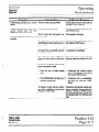
Topic
Page
Chapter Introduction
PREFACE .................................
...................................................................................................................
ABOUTTHlSCHAPTER
..............................................................................................................................
QUICK-REFERENCE CHART.. ... ..........................................................................................
..[ . ......................
Intro-l
Intro- 1
Intro-2
Section A - FCC Requirements
RADIO AND TELEVISION INTERFERENCE ......................................................................................................
HEARING AID COMPATIBILITY .......................................................................................................................
RES’ONSII3ILITES
..............................................................................................
...........................................
User Responsibilities ..................................................................................
..................................................
Telco Responsibilities ..................................................................
..................................................................
A-l
A-l
A-2
A-2
A-2
Section B - System Components
I
STANDARD COMPONENTS .........................................................................
.....................................................
One Key Service Unit (KSU) ...................................................
........................................................................
Up to Twelve Telephone Sets.. .......................................................................................................................
OPTIONAL COMPONENTS ................................................................................
................................................
One Door Answer Unit ..................................................................................................................................
Up to Two Power Fail Transfer Units ...............................................................................................................
Up to Eleven Off Premises Extension/Data Interface (OPX) units ..........................
................................................
One Station Message Detail Recorder (SMDR) Interface .....................................................................................
Set Stands/Wall-Mounts .............................................
....................................................................................
Designation Cards ............................................................................
............................................................
Face Plates............... .....................................................................................
...............................................
B-l
B-l
B-l
B-2
B-2
B-2
B-2
B-2
B-3
B-3
B-3
Section C - Technical Specifications
CONNECl’ORS .................................................................................................................................................
SMDR INTERFACE UN-IT (Optional) ...................................................................................................................
ENVIRONMENTALREQUIREMENTS
................................................................
................................................
POWERREQUlREMENTS ..................................................................................................................................
STATION NUMBERING PLAN ...........................................................................................................................
SYSTEM CAPABILITIES ...................................................................................................................................
.. .. .. . .. .. .. .. . ..
. . . . . . . . . . . . . . “......
>
.. . .. .. .. .. . .. .. . .. .. * .. .. . . . . . . *.**
. . . . *.......-
TRILLIUM
Telephone
Systems
c-1
C-l
c-2
c-2
c-2
c-2
I
. . . . . . . . . . . . . . . . .. . . .. .. *..a.**
. . . . . . . .. .. . . . . . . . . .. *...*...*
. . . . . . . . . . . .. . . .. .. .. .. . . .. . . .. . . .. .. .. .. . . .. .. . . .. . . .. . . .. . . .. . . .. . ..*. . . . .. . . .. .........................
. . . . . . . * . . . . . . . . . . . . . . . . . .* ..........................................-.................................-............-.....................,....
. . . . . . . . . . . . . . . . . . . .....................--..........................................-..........................
. . .. .. .. . ..
. .. .. .
Panther 6 12
............*...........“-....s.........s.....,....*....................................-.......
........................
......“..“_”
........,....................,.....
....................Page
..“..”
..........,.....
........i..
......................,........................”
Table of
Contents
_
.....................
...
. .........
..-...
. ...........
-.**
....................................................
....................
Technical
ServicManu
.........
.
. .
.........
.......
--.
................................
.........................................
.
. ...............
...
. .
...
-.
-.
.............................................................
. . . ...
. .....................................................
Topic
:::::::::::::::::::::::::x::“:‘-::::::::::::
::::
:
‘-~:
Page
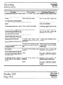
Section D - Connection Procedures
INSTALLlNG THE KSU ...................................................................................................................
STEP 1:
D-l
Site Preparation. ...........................................................................................................................................
D-l
Backboard Installation .........................................................................................
..........................................
D-l
~~Systemunclating ..........................................................................................................................................
D-l
KSU Installation ........f ..................................................................................................................................
D-l
STEP 2:
CONNECTING INCOMING TELEPHONE LINES ................................................................................
D-2
INSTALLING STATION WIRING .....................................................................................................
STEP 3:
D-2
Station Wiring Table .....................................................................................................................................
D-3
STEP 4:
CONDUCTING THE INITIAL SYSTEM AND STATION TESTS ...........................................................
D-5
CONNECTING THE BACKUP BATTERY ..........................................................................................
STEP 5:
D-5
STEP 6:
CONNECTING DOOR ANSWER UNIT AND DOOR MODULES ...........................................................
D-6
Door Answer Unit Installation ................................................................................
.........................................
D-6
Door Module Installation ........................................................................................
........................................
D-6
DoorAnswerUnitTest..
..................................................................
.............................................................
D-7
STEP 7:
CONNECI’ING THE MUSIC SOURCE ...............................................................................................
D-8
Music Connection .........................................................................................................................................
D-8
Music Test.. ...........................................................................
......................................................................
D-8 /
STEP8:
CONNEC’l.ING THE EXTERNAL PAGING EQUIPMENT .....................................................................
D-9
Equipment Connection ...................................................................................................................................
D-9
Paging Test.. ................................................................................................................................................
D-9
CONNECTING AN EXTERNALLOUDBELL
STEP 9:
.....................................................................................
D-9
muipment Connection ...................................................................................................................................
D-9
Loud Bell Test. .............................................................................................................................................
D-9
STEP lo:
CONNECIING THE OPX UNlT ....................................................................................................
..
. D-10
OPX Unit Connection .................................................................................................................................
D-10
OPX Unit T est. ...........................................................................................................................................
D-10
STEP 11: CONNECTING THE SMDR INTERFACE UNIT .................................................................................
D-11
SMDR Interface Unit Installation ..................................................................................................................
D-11
SMDR Interface Unit Test ...........................................................................................................................
D-11
SMDR Printout Formats ...............................................................................................................................
D-11
STEP 12: CONNECl-INGTHEPOWERFAILTRAN!WERuNITS
. . . ...................................................................
D-12
Power Fail Transfer Unit Installation ...............................................................................................................
D-12
Power Fail Transfer Unit Tes t. .......................................................................................................................
D-13
STEP 13: INSTALLJNGANEXTERNALAMPLIFIER
......................................................................
. ............... D-14
TRILLIUM
Telephone
Systems
’
/
1).
Technical
Service
Manual
Chapter
Introduction
..-...........................
.................................
. .......................................................................
::::::::‘-::
::::::::::::::
“2
.“.
..-........................................................................
..............................................
;r .................................
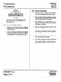
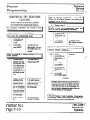
PREFACE
ABOUT THIS CHAPTER
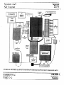
The Panther 612 Electronic Key Telephone System is a
state-of-the-art system that incorporates sophisticated electronics to meet ti communications needs of today’s home,
office, and small business user.
This chapter has also been designed specifically to enable
technicians to install, operate, and maintain the Panther 612
Electronic Key Telephone System. Information is presented
in a logical order, without undue wordiness - to help the
technician find, understand, and use the relevant information, quickly and easily.
It’connects six outside telephone lines (only five if the op
tional Door Answer Unit and Door Modules are installed)
with up to twelve station Sets- which are all wired in a
star configuration Both a tone only key service unit (KSU)
and a tone/rotary KSU are available. Also, both Handsfree
and Non-Ham&free Sets are available; the Handsfree Sets
also include Busy Lamp Field (BLF) indicators that show
the status of all system stations.
Therefore, for example, the Connection Procedures are sep
arated into concise steps that have a logical and necessary
sequence; and reference material (Technical Specifications,
Feature Programming,
Operating
Instructions,
and
Troubleshooting) is presented in a variety of easy-to-follow,
visible-at-a-glance tabular formats.
Common and private speed call numbers, call transferring,
door answering (with optional Door Answer Unit and Door
Modules), internal monitoring, conferencing (up to 3 parties), internal intercom paging (station-to-station, zone, and
all page paging), external loudspeaker paging, call detail and
account code recording (through an optional SMDR interface unit), and last number redialing are just some of the
many features offered.
To acquaint yourself with this chapter, please review the
Table of Contents and spend a few moments browsing
through the different sections.
The attractive, well-designed system makes feature programming and operation very easy. In addition, the Panther
system is designed to allow easy interfacing with modems
and answering devices through an optional OPX device.
If you have an installation, operation, or troubleshooting
problem that you cannot solve by using this chapter (and
that your dealer cannot help solve), call TRILLIUM
Customer Service at l-800-848-2444 (inside California, call
l-800422-7600).
CAUTION
Panther equipment is sealed. Breaking the seal
will void your warranty.
The fully sealed Panther 612 Electronic Key Telephone
System may be installed in either a standalone mode or behind a CENTREX or PBX. The microprocessor-controlled
circuitry operates all system communications and the flexible programming.
An optional external backup 24 V battery can be connected
to the system; the backup battery is automatically brought
on line in the event of a power failure, thus preventing interruptions in telephone service.
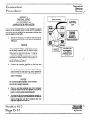
NOTE
For your ready reference, a chart summarizing
indicator signals appears on the back of this
page.
:
Also, in the event of a total system failure, incoming lines
will be transferred to standard sets if optional Power
Transfer Units have been installed in the system.
. .
. .
>
. .
. .
. .
. .
. .
. .
.
.
. .
. .
.
.
. .
. .
. .
. .
. .
. .
. .
. .
. . .
. . .
. .
. .
. .
. .
.
.
. .
. .
.
.
. . . . .
. **.CI
TRILLIUM
Telephone
Systems
. .
. -
. .
. .
.
.
.
. .
. .
. .
. .
. . .
. . .
. .
. .
.
.
. .
. .
. . . .
. . . .
. .
. .
.
.
. .
. .
. .
. .
. .
. .
. .
. .
.
.
. .
. .
.
.
. . . .
. . . .
. .
. .
. . . .
. . . .
.
.
. .
. .
. .
. .
. . . .
. . . .
. .
. .
.
.
. .
. .
. .
. .
.
.
. .
. .
. .
. .
. .
. .
. . . . .
. . . . .
. .
. .
. . .
. . .
. .
. .
. ................................
. . . . . . . . . . . . . . .
. . . . . . . . . . . . . . . . . . . . . . .
.....................................................-................................................
. .
.
. .
. .
. .
. .
-
.
. .
. .
. .
I
. .
.
. .
.
. .
.
. .
. .
. .
. .
.
. .
. .
. .
.
. .
.
. .
. .
.
. . .
.
. .
. .
. .
”
. . . . . . . . . . . .
.......................
. . .
. .
.
. .
. . .
.
. . .
_,
Panther 6 12
Page Intro- 1
.. .. .. .. .. .. .I..... . . . . .. .. .. --.~
. . . . . . . .. .. .. .. .. I. . .. .. .. ..-...............................................
. “_...I
. . . . . . . . . . . . . . . . . . . “”
. . . . . .....................................................:
. . . . . . . . . . . . . . . . . . . . . . . . . . . . . ..-...............
. . . . .- - . .. .. .. .. .. .. .. ,. .. .. ...”
. . . . . .. .. .. .. .. .. .. .. .. .. .. .. .. .. .. .. .“.”. . -.a. .. .. .. .. .- .. .. .. .. .. .. .* .. .. .. .. .. .. .. .. .. .. .. .. .* .. .. .. .. .. .. .. *. .. .. .....”
. . . . . . . . . ...”
k..
...._._._....._._..
. . . . . ..-.-_.....................
Chapter
Introduction
................
......
..--
..-.
.....
...“.
__._
I ......:..-
Technical
Servic’ -.;
Maw
..............
I..
...........................................................................................................................................................................
..............
-.
..................................................
.
QUICK-REFERENCE
...
.
................................
........................................
..-
.........................................
. .
.
...::::::
j
.
“‘“~::“==:
:::::::::
:::
::::::::::::::
:”
CHART
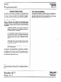
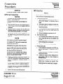
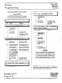
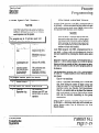
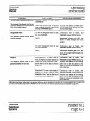
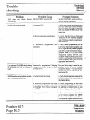
The Panther 612 Electronic Key Telephone System lets
users lmow what is happening with calls and lines through a
series of indicator patterns. These indications are summarized in the chart on this page. Specific indications are
desqibed at the appropriate places throughout the procedural material in this chapter.
Lim h&atorActbn
Lhestatus
lhehuseam
mdsiv.hokl*
inauapkn
-
.
. . . . . .
. . . . .
. .
.
. .
. . . . . .
..1.*.......1.-
.
. .
.
. .
. .
-
.
.
. .
.
. . .
. .
.
.
. .
. .
. . “m”
. u
. .
. .
.
. .
..“..--“.“*...-..“-~-.-..“.*
. .
.
, .
. . .
.
. .
.
. .
. .
. .
. .
. .
. .
.
. ...”
. .
.
. .
.
. .
. .
. I
.
. .
. .
. .
.
. .
.
. .
. .
.
. .
. .
. .
. .
.
. ...”
. .
. .
. .
. .
.
. .
. .
. .
.
. . .
. ““..‘+”
. .
.
. . .
. . .
.
. .
.
. .
. .
.
. .
.
. .
. .
. .
. ..-..........
“.._.,“...I...”
*...*
. .
. .
. .
.
. I
. .
. .
. .
.........................-....-...........--..”
. ..._.”
.
. .
. .
...”
. .
........._.”
. .._._
“.._
_...........,,...
Panther 6 12
Page Intro-2
.
.
. .
. .
. . .
. . .
-“..I
. -
.
. .
. .
. . . ..-........-................-..................................................................................
. . . .
.
.
..“I_”
. . . . . ..“...rn
. . . . . I
.
........
..__..-_
%i LLIUM
Telephone
Systems
”
.
. .
. .
.
. .
.
.
.
.
. .
I
.
.
. .
. -“..-
.
. .
. .
-.-
. .
.
. .
I
. .
. .
.
. .
. .
. .
.
. _.“I
.
. .
. .
. .._.....”
.
. .
. .
. .
I
. .
.I.......
.
..-...................”
_
.-.........-..
.
“.“__
.
. . .
. .._...........................-..............--.............
-.,._.
*...*-._”
”
. .
.._..._.
“..”
__.......
“.”
. .
.
.
. .
. .
. .
. . .
.
. .
“.“..
. .
. .
__)
::::::::::::::::::::::::::::::::::::::::::::::i
:::............
.................................................
I..........................................,
...........................................
......*......,.....-. ....,.............-....._...................................*......................................................................................................
i
Technical
Service
Manual
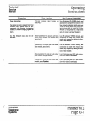
FCC
Requirements
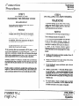
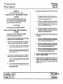
RADIO AND TELEVISION
INTERFERENCE
WARNING
HEARING
AID COMPATIBILITY
The Panther 612 Set is compatible for those requiring a
hearing aid as defined in section 68.316, Part 68 of FCC
Rules.
The Panther 612 Electronic Key Telephone
System generates and uses radio-frequency energy and - if not installed and used in strict
accordance with these instructions - may
cause interference to radio and television
reception.
The Panther 612 Electronic Key Telephone System has been
certified to comply with the limits for a Class B computing
device, pursuant to Subpart J of Part 15 of the Federal
Communications Commission (FCC) Rules which are designed to provide reasonable protection from radio and
television interference in a residential installation. However
there is no guarantee that interference will not occur in a
particular installation.
(
If interference is encountered, test to determine if the unit is
at fault by unplugging the Key Service Unit (KSU) from the
wall outlet
If unplugging-the KSU removes the interference, ay the following corrective measures, singly or in combination, until
the interference is eliminated:
l
Change the location or position of the indoor receiving antenna of the radio or television.
.
Relocate the Panther 612 Set or KSU in relation to
the radio and television receivers experiencing
interference.
.
Plug the KSU into an outlet that does not also serve
radio or television sets.
If further help is needed, consult your TRILLIUM dealer or
an experienced radio/television technician - or refer to the
FCC’s booklet, “How to Identify and Resolve Radio-TV
Interference Problems.” It is available from the US
Government Priutiug Office, Washington, DC 20402 (stock
number OO4-000-003454).
/’
\
TRILLIUM
Telephone
Systems
‘ Panther-6 12
Page A-l
.
. . . . . . . . , . . . . . . --.................................................
_. . . . . . . . . . . . . . . . . . . . . . . . . . . . . . . . . . . . . . . . . . . . . . . . . -. - . .. .. .. .. .. .. .. .. .. .. .. .. .. .. .. .. .. .. .. :.::::::::::::::::::::::::::::“‘:::::::::::~::~:::::::::.~:::::::::::::::::::
.
. . . . . . . . . . . . . * I.....
:::::
:::::::::
z ::::::::::
c:.::::
::::::;
z :::::
:::::::x-:::::.
--
Technical
Service
Manual
f .-.
::::::::::::::::::::..1...::::::::::::::::::::::::::::::~:::::::::::::::::::::::::::::::::::::::::::::::::::::::::::::::::::::::::::::::;::::::::::::::
FCC
Requirements
RESPONSIBILITIES
The FCC’s rules permit the Panther 612 Electronic Key
Telephone System to be connected to the telephone network
via a jack or jacks provided by the telephone company
(telco). These jacks are not provided for coin or party lines.
Telco Responsibilities
The telephone company is required to give you adequate notice of any changes it makes in its technical operations cr
procedures that may affect the compatibility or use of your
Panther 612 Electronic Key Telephone System.
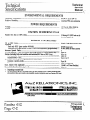
User Responsibilities
Before connecting your Panther 612 Electronic Key
Telephone System to the telephone lines, you must contact
the telephone company and provide them with the following
information:
.
l
Telephone numbers of the lines to which the
Panther 612 Electronic Key Telephone System is to
be connected (lines 1 through 6)
FCC Registration Number (found on the side of the
Key Service Unit or KSU: the number for either the
tone only KSU is EBS78T-71738-KF-T, or, for the
tone/rotary KSU, the number is EBS78T-71738=-E)
.
Ringer Equivalence Number (also found on the side
of the KSU: the number for either version of the
Panther KSU is l.lB)*
.
USOC jacks required (usually three 4-conductor.
RJ14 modular jacks)
You also have the responsibility to disconnect a malfunctioning Panther 612 Electronic Key Telephone System from
the telephone lines until the cause of the malfunctioning is
identified and repaired. Otherwise, the telephone company
may temporarily disconnect service.
* The Canadian Department of Communications load number for the Panther 612 Electronic Key Telephone System is
16-B.
=::::::::::::
~ ::::::::::::::
::::::::::
:::::::::::::::::
::::z*l::::"..""..
............."".."
....."...
.....-.........."
.......-......."...""......-.
-- -...
-........"
....I..........I......""
..."."..".."..,"....."
....I........"
...-..
-...I
TRILL;UM
Panther 6 12
:e A-2
pag
Telephone
Systems
(
Technical
Service
Manual
System
Components
STANDARD COMPONENTS
One Key Service Unit (KSU)
Part Number 90-0166 (tone only)
or
Part Number 90-0084 (tone/rotary
The ~onelrotary key service unit (KSU) for the Panther 612
Electronic Key Telephone System can be programmed to
operate with either dual-tone, multi-frequency (DTMF) or
rotary (pulse) signaling. The signaling on each Central
Office (CO) line can be programmed independently. The
tom only KSU operates only with DTMF signaling. Other
than signaling differences, both KSU models look alike and
operate iden ticall y.
<
/-
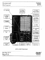
The KSU has three connectors on its left side (labeled
C01.2, C03.4, and CO%) to attach the six incoming telephone company (telco) CO lines - one connector for each
pair of lines (line 6 must be left vacant if the optional Door
Answer Unit is installed). Also on the left side of the KSU
are connectors labeled DOOR (used for the optional Door
Answer Unit), PAGE (used for external paging equipment),
MUSIC (used for an external background and on-hold music
source). POWER FALL (used for the optional Power Fail
Transfer Unit).
Next, the KSU has one recessed light-emitting diode (LED)
indicator (labeled STATUS), four miniature dual in-line
package (DIP) switches (labeled, from top to bottom, 1
PROGRAM [used to return features to their default, factory
preprogrammed conditions], 2 PROGRAM [used to program system features], 3 [not used], and 4 BATTERY [used
to save feature programming]), and one recessed pushbutton
(labeled RESET).
Near the bottom left of the KSU is a 50-pin connector, labeled STATIONS 10 TO 21/LOUD BELL, that is used to
connect the KSU to the station wiring main distribution
frame (MIX) - and, through the MDF, to alI the system
stations. The last pair is also optionally available for connecting an external loud bell or other sounding device
through an external dry contact interface unit.
On the bottom of the KSU is a connector labeled SMDR
(used for the optional SMDR Interface unit).
c
=:=:I”
:::::::::::.
x:;
::::::::
;:r<
::::::::::::::::::;
:::::::::::::
~‘::.w’“-“:“:~“:::..-
The KSUs power cord (at the top of the KSU) plugs into a
110 V ac outlet (but only at the appnpriate time; see the
Connection Procedures section). A grounding wire (12
AWG, solid copper) which connects to the top of the KSU
must be attached to a ground clamp, umally on a water pipe.
An input connector (labeled EXTERxti
BATTERY) for
an optional 24 V backup battery is aha provided at the top
of the KSU. If ac power is lost, the switchover to backup
battery power is automatic when the qcional backup battery
is connected.
The unit comes with 4 screws for mmting
backboard
the KSU on a
Up to Twelve Telephone tits
Part Number 90-0266
(non-handsfree)
&t Number 90-0168
(handsfree with busy lamp field)
Other than the handsfree operation and the busy lamp field,
these two models look alike and operaa: identicatly. For example, both have an attractive black marre tIni&.
Each Set’s base has twelve dual-functkm statiort select/speed
call keys (labeled 10 through 21- tix top key is also used
for last number Redial), six line seleukeys (labeled 1,2,3.
4,5, and 6), seven dedicated functim keys (labeled Hold,
Flash/Cancel, Conference, Intercom, Speed,
Speaker,andMic.on/off) anda tone d&l keypad
The line 1,2,3,4,5, and 6 keys, the Uercom key,and the
Mic.on/off key have accompanying szus indicators. And,
only on handsfreebusy lamp field (HFELF) Sets, each station select key (10 through 21) also has an accompanying
status indicator.
Finally, the base has a speaker volume control (a sliding adjustment) and a ringer control switch (a ‘J-position switch,
for low, medium, and high volume riqing).
Each Set also includes a telephone hardset and two modular
cords - a 4-conductor, coiled cord fa connecting the handset to the Set, and a 4-conducur modular cord for
connecting the Set to the station wiring jack.
. . . . . . . . . . . . . . . . . . . . . . . . . . . . . . . . . . . . . . . . . . . . . . . . . . . . . . . . . . . . . . . . . . . . . . . . . . . . . . ..-...........................
. . . . . ...”
. . . . . . . . . . . . “...
. . . . . . . . . . . . . . . . . . . . . ...”
. . . . . . . . . . . . . . . . . . . . . . . . . . . . . . . . . * . . . . . ..”
-... . . . . . . . . . . . . . --.....“*..*
._...............
I
. . . . . . . *..
,-
TRILLIUM
Telephone
Systems
’ Panther 612
Page B-l
.Technical
Service
Manual
..................................................................-A ................d...
:::::::::::::::::::::“::::::::::::::::::::::::::::::::::::::::::::::;:::::
.,.................................................................
...”....................................................
.*.*
.......- ......,................................
............................................. C
System
Components
Up to Eleven Off Premises Extensibnl
Data Interface (OPX) units
Part Number 90-0308
OPTIONAL COMPONENTS
One Door Answer Unit,
Part Number 90-0058,
With One or Two Door Modules,
Part Number 90-0057
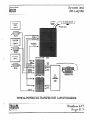
‘The OPX unit converts a 4-wire interface to a 2-wire interface, allowing a single line telephone to be connected to any
spare station jack - except station 10. It also allows 2-wire
devices to be co~ected at a distance greater than the system
2&lO feet limit for Sets. The OPX unit also simulates CO
line charactistics, allowing a modem or an answering machine to be co~ected
to the system. Finally, the OPX unit
allows a remote device to be connected to your system at
any distance via a CO line.
The Door Answer Unit (also known as the Door Answer
Control) is installed next to, andconnects with, the KSU. It
serves as the interface between the system’s stations and the
one or two installed Door Modules (also know as the Door
Answer Boxes) at the desired doors or entryways.
Together, these units enable signaling and conversation between Set users and visitors. Like the KSU, these units come
equipped with mounting screws.
When the user lifts the single-line telephone’s handset, an intercom connection is made to the Panther system. Also, by
dialing a special code, the off-premise user can access any
of the Panther system’s outside lines,
A visitor, by pressing the door bell button on a Door
Module, generates a distinctive tone (four groups of 4 short
tones for Door Module 1, four groups of 2 long tones for
Door Module 2) that will sound at all Sets programmed to
ring on line 6 and causes the indicator for line 6 on all Sets
to WlNK. Also, each Set user can generate a calling tone
that will sound at Door Module 1 only.
One Station MessageDetail Recorder
(SMDR) Interface
Part Number 90-0169 only
This unit allows information on system, line, and station
usage to lx captumd and recorded.
Up to Two Power Fail Transfer Units
Part Number 90-0052
(I .
The Power Fail Transfer Unit automatically takes over in the
event of an electrical power failure, allowing for continued
telephone service during the emergency. One Power Fail
Transfer Unit can handle up to 4 incoming lines.
When power fails, the Power Fail Transfer Units transfer incomingCOlines(uptoall6ofthem-ortbe5linesinuse,
if the optional Door Answer Unit with Door Modules is installed) to pre-installed srundard telephone sets (not to
Panther 612 Sets).
:::::::::::::::::::‘~::::::::::::::::::::::::::::::::::::::::::::::::::::::::::::::::::::::::~::~::::~::::::::::::::~::::.
Panther 6 12
Page B-2
-.......-.._......_
“::::“:“~n~:“““~:~=-::::~:~:~
I
..“...” . . . . . .. .. .. .. . . . . .. .. . . . e.....
. . .
.-.....
.. .
. . . ... . . ..“...I.......
TRILLIUM (
Telephone
Systems
_-
.
. .
. .
. .
. .
. .
. ._
. . . .
. .
.
.
. .
. .
. .
. .
. .
. .
.
.
. .
. .
.
.
. .
. .
. .
. .
. .
. .
. .
. .
.
.
. .
. .
. .
. .
. . .
. . .
. .
. .
. .
. .
. . .
. . .
. .
. .
. .
. .
.
.
. .
. .
.
.
. .
. .
. . . .
. . . .
. .
. .
. .
. .
. .
. .
. .
. .
.
.
. . .
. . .
.
.
. .
. .
. .
. .
. .
. .
. .
. .
.
.
. .
. .
. .
. .
. .
. .
. .
. .
. . . . .
. . . . .
. .
. *
.
.
. . . . . .
. . . . . .
. .
. .
. .
. .
. .
. .
. .
. .
.
.
. . .
. . .
.
.
. .
. .
.
.
. . . .
. . . .
. . . .
....
. . . . . .
* ..........
.
. .
..I
. . . . . . . . . . . . . . . . . . . . . . . . . . . . . . . . . . . . . . . . . . . . . . . . . . . . . .
# ....................................................................................................................................
.
. .
.
. .
. . .
.
. .
. .
. .
.
. .
.
. . .
. .
.
. .
. . .
.
. .
.
. . .
.
. .
.
. . .
.
. .
. .
. .
. .
.
. .
. .
. .
. .
.
. . .
. .
.
.
. . .
. .
.
.
Technical
Service
Manual
System
Components
:::::::::::
:‘.:::::
:::::::::::::::
:::::::::::::::::::;
:::::::
:’..............***.**.*
.........*...*...*
.....*.......*...........................................................
~............
........................................
Set Stands/Wall-Mounts
Part Number 90-0087
Each Set may be placed on a desk - or mounted on a wall
using the Set Stand/Wall-Mount Bracket (available in packages of 10).
The same bracket can also be used to provide a heightened
viewing angle when used with the Set on a desk- or tabletop*
Designation Cards
Part Number 90-0192
(for non-handsfree Sets)
Face Plates
Part Number 70-0171
(for non-handsfree Sets)
k-t Number 70-0172
(for handsfree/busy lamp field Sets)
Face Plates cover and protect the Designation Cards. You
may order spare Face Plates for your system.
Notice that each type of Set uses a d$erent Face Plate.
Krt Number 90-0193
(for handsfree/busy lamp field Sets)
Designation Cards are used to list the eleven private speed
call numbers and identify the assignment or location of the
twelve system stations.
Although each Set comes equipped with one installed and
one spare Designation Card, you may order additional cards
(in packages of 10) for your system.
Notice that each type of Set uses a different
Designation
““‘““‘::::“~~~:~::::::::::::::~~~~:::::::::::::::::~~:~:::::~~:::::::::~~:::::::::::::~~:::::::::::::::::::::::::::.~::::::::::::::::::~::::::::::~::::::::::~::
*::::““..:::::::.
z::::“:::::::::z
c.
TRILLIUM
Telephone
Systems
I
Panther 6 12
Page B-3
Technical
Service
Manual
Technical
Specifications
.
._
.
.
.
.__
._._
.
.
.
.
.
.
.
.
.
.
.
.
.
.
.
.
.
.
.
.
.
.
.
.
.
.
.
.
.
.
.
.
.
.
.
.
.
.
.
.
.
.
.
.
.
...............~............::::::::::::::::::::::::::::::::::::
(. ,. ...
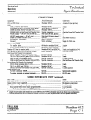
CONNECTORS
Equipmenf
JackstConnections
Cable Pairs
CO or PBX lines ..................................................
KSU:
C01.2, C03.4, and C05.6.. ..............................
STATIONS 10 TO 21 (to station wiring MDF) ....
DOOR (to Door Answer Unit jack DA). ..............
POWER FAIL (to first Power Fail Transfer Unit) ..
PAGE (output - 2.00 mV rms into 600 f2) .........
MUSIC (music input - 50 mV rms). .................
SMDR (to SMDR Interface unit) ........................
EXTERNAL
BATTERY ...................................
Ground ..........................................................
Station wiring MDF:
To station jacks.. .............................................
To dry contact interface (2 A, maximum). ............
Panther 612 Sets (to station jacks) ............................
Door Module (to Door Answer Unit D 1 and D2). .........
Fit Power Fail Transfer Unit (optional):
C01.2 & C03.4 (from incoming lines l-4). .........
TK1.2 & TK3.4 (to KSU jacks C01.2 & C03.4).
CNJ (to KSU jack POWER FAIL). ....................
CNK (to 2nd Power Fail Transfer Unit jack CNJ) ..
Second Power Fail Transfer Unit (optional):
C01.2 (from incoming lines 5 & 6). ...................
TK1.2 (to KSU jack C05.6) ..............................
CNJ (to 1st Power Fail Transfer Unit jack CNK) ...
SMDR Interface unir
To KSU connector SMDR.. ..............................
To printer, terminal, or personal computer.. ..........
Modular
A total of 6 (one per line)
RJ14C . .. .. . .. .. . . .. . .. . .. . ..
Modular RJ14C .. .. . .. .. . .. . .. .. . .. ..
50-pin RJ21C to 66-block . .. .. .. ..
Modular RJ25C .. . .. . .. .. . .. . . .. .. . .. .
Special connector . .. . .. .. .. .. . .. . ... ..
Mini-Jack l/&inch, phono) . ... .. ..
Mini-Jack (l/&inch, phono) ... .. ..
Special . . . .. .. . . . .. .. . . . . .. . . . .. . . . . .. . . . .
Molex connector .. . .. .. .. . . ... ... . .. ..
Screw terminal . . .. .. . .. .. . .. .. .. .. . .. .
2each
25
3
(See first Power Fail Transfer Unit)
1
&e SMDR Interface)
1’
Single 12 AWG wire
66-block to modular RJ14C.. .....
66-block to screw terminals.. .....
Modular RJ14C (or RJ25C**) ....
Screw terminals.. .....................
2 each*
1
2 each, cord supplied (or 3**)
1 for each module
Modular RJ14C.. .....................
Modular RJl4C.. .....................
Special connector.. ...................
Special connector.. ...................
2each
2t.!ach
1 (cable supplied)
(See 2nd Power Fail Transfer Unit)
Modular RJ14C.. .....................
Modular RJ14C.. .....................
Special connector.. ...................
2each
2each
1 (cable supplied)
special ...................................
DB-25 ....................................
RS-232 cable
Special (cable supplied)
SMDR INTERFACE UNIT (optional)
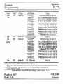
Data code.. ............................................................................................................
Data rates (SMDR switch-selectable) .........................................................................
Output device (user supplied) ....................................................................................
Time before recording starts (programmable) ...............................................................
Grace period before timer starts (programmable) .....................................................
Account Codes (as they appear in SMDR printout) .......................................................
ASCII
300.600. or 1200 bits per second
8a-character, serial printer
lto6lseconds
ltol6seconds
“A”+ 4 user-entered digits
* Length of each station cable should not exceed 2000 feet of 2A AWG; ail station runs are star (home,r@ configurations
** Sets may alternatively use a 6-conductor modular cord-toRJ25C jack (to gain access to the Set’s speaker terminals)
c
TRILLIUM
Telephone
Systems
I
Panther .612
Page C-l
Technical
Technical
Service
Specifications
Manual
......................................................................................................................................................................................._.
..................._.
..............-_.......
....................................................................................................................................................................................
“_”...............
^._..............._......
::::::~:::::::::::::::“::::::::
c
ENVIRONMENTAL
REQUIREMENTS
to104
“F)
Operating Temperature . . . . . .. . . . . .. . . . .. . . . . .. . .. . . . .. . . . .. . . . . .. . . .. . . . . .. . . . .. . . .. . . . . .. . . .. . . . . . .. . . . .. . .. . . .. . 0 to 4I) “C (32
Relative Humidity .. . . .. . . . . .. . . . . .. . . . . . . .. . . . . . .. . . .. . . . . . . .. . . . . .. . . . . . . . .. . . . . .. . . . . .. .. . . . . .. . . . . . .. . . . . .. . . . .. Less than 90%. noncondensing
POWER
REQUIREMENTS
Voltage .. . . . . . . . . . . . . . . . . . . . . . . . . . . . . . .. .. .. . . . . . . . . . . . . .. .. . . . . . . . . . . . . . . . . . . .. .. . . . . . . . . . . . . . . .. . . .. .. .. . . . . . . . . . .. . .
Current . . . .. .. .. . . . . . . . . . . . . . . . . . . . . . . . . . . .. . . .. . . . . . . . . . . .. .. .. . . .. .. .. . . . . . . . . . . . . . . . .. .. . . . . . . . . . . . . . . . . . . . . .. .. . . . .
STATION
NUMBERING
PLAN
Panther 612 Sets or OPX Units . .. . .. . .. . .. . .. .. . . .. . . .. . .. . .. . .. . . .. . .. . . .. .. .. . . .. . .. . . .. . . .. . .. . . .. .. .. . .. . .
SYSTEM
115 V ac (* 10%). 50/60 Hz
1.0 A, maximum load
10 through 21 (OPX unit not allowed on station 10)
_
CAPABILITIES
CO or PBX Lines ..................................................................................................
6 (only 5 with Door Answer Unit)
Signaling:
Tone only KSU (part number 90.0166) ................................................................
DTMF (tones) only
Tor&otary KSU (part number 90.0084 - each line independently programmable) ...... DTMF (tones) or rotary (pulses)
Intercom Speech Paths ............................................................................................
3
OPX unit (optional - used with modem, answering machine, or remote standard set). ........ upto 11
Stations (including both non-handsfree and handsfree/BLF Sets or OPX Units). .................
upto 12
Non-handsfree Sets ...........................................................................................
upto 12
Handsfree/BLF
Sets ..........................................................................................
UptogorBt
Speed Call Numbers (up to 26 digits, pauses. or flashes each):
Common (system-wide) ....................................................................................
Upto
Private ...........................................................................................................
UptollateuchSet
Door Answer Unit (optional) ...................................................................................
1 (with 1 or 2 Door Modules)
Power Fail Transfer Units (optional) ..........................................................................
up to 2tt
t
Depending on system load
tt 1st unit transfers up to 4 incoming lines; 2nd unit transfers up to 2 more incoming lines;
all transferred lines are routed to p&nstalled stun&rd telephone sets (not Panther 612 Sets)
AtoZ
. . . . . . . . . .. .. .. .. .. .. . .. .. .. .. .- -“.‘:::::::“:::::::““::“::“:::“::”:::”
. . . . . a...
Panther 6 12
Page C-2
KELLATRONICS,
::::::::
/
(
INC
~::“::“:::”
-........”
_II”
._....-”
. . .. . .
..“-
. . . . . . . . . ..___
. . ...”
. .. ..
I
“....““‘::“:“::::.~:::~~~
TRILLI-UM (
Telephone
Systems
Technical
Connection
Procedures
Service
Manual
/ :::::::::::::::::::::::::::::::::::::::::::::::::::::::::::::::::::::::::::::::~::::::::::::::::::::::::::::::::::::::::::::
. . .
I...
STEP1
INSTALLING THE KSU
. .
.
. .
. .
. .
. .
.
.
. .
. .
. . . .
* . . .
. .
. .
.
.
. .
. *
.
Clean, dry, and well ventilated (should meet the environmental requirements listed in Section C)
.
Within seven feet of the incoming CO, CENTREX,
or PBX line terminations
WMNING
If you are in area subject to power transients,
install a surge protector on the dedicated outlet
.
Within five feeC of a dedicated 110 V ac, 60 Hz, 3wire grounded outlet - an outlet that is not on a
wall switch
.
Not too distant from station terminations (the maximum distance to each station is 2000 feet, using 24
AWG wiring)
.
A 30” by 30” area of walI space should be reserved,
allowing room for Power Fail Transfer Units, the
SMDR Interface unit, and the Door Answer Unit
(whether they are being installed now or might be
in the future)
Backboard Installation
If the KSU is to be mounted on a concrete or masonry wall,
a l/2-inch thick plywood backboard is recommended.
Depending on the wall’s construction and your method of installing the backboard, you might need screwdrivers
(various kinds and sizes), drills and bits (various sizes), # 10
masonry screws with plastic anchors (4 of each), or l/4”
screws wjkwall grip screw anchors (4 of each).
. .
. .
.
.
. .
. I
. . . .
. . .
. .
. .
. . . . .
. . . . .
. .
. .
. .
. .
.
. ::::::::::::::::::::::::I::::::::::::::::::::::::::::::::::::::::::::::~::::::::::::::::
System Uncrating
a
Carefully unpack the System and confirm that all
ordered parts are present by checking them off
against the Customer’s order sheet and the packing
list
h
Make sure that the customer’s feature requirements
have been documented on a Customer Feature
Selection Form.
Site Preparation
Because the KSU is at the heart of the operation of the
Panther 612 Electronic Key Telephone System, ensure that
its installation site meets the following criteria:
. .
. .
KSU Installation
a.
Mark the position of the 4 screw holes needed to
mount the KSU on the backboard.
b.
Drive four screws (supplied) until their heads are
within l/8-inch of the lxxrd‘s surface.
c.
Using the four keyhole slots (narrow end up) in the
side flanges of the KSU cabinet, hang the unit on
the four screws and tighten them securely.
CAUTION
Failure to properly ground the KSU may void
your Panther .612 Electronic Key Telephone
System warranty.
d
Connect the ground lug at the top of the KSU to a
cold water metal pipe or ground stake, using copper
wire that is 12 AWG or heavier (not supplied).
Be sure that the cold water pipe’s metal continuity
is not broken by the use of plastic pipe.
A ground stake should also meet the installation requirements of your local electrical code.
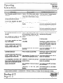
e . At the electrical service panel, equip the electrical
breaker for this outlet with a locking clip - or
mark it with a label to serve notice that this unit
should not be disconnected or shut off.
Mount the backboard at least 12 inches above the floor.
l
TRILLIUM
Telephone
Systems
I
Panther 612
Page__.......”
D-l..._,
...-.............I............
................”
........“.I
.......”
...-I.-....
.............-...................................................
.
._._................_.......L.._..“..”
....................
_..............................”
,......”
...........e..........*
Technical
Service
Manual
........................................-..........................................
..............................................................................
:::::::::::::::
::::::
~:::::::::
“‘:::::::::::::::::::::
f
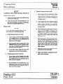
STEP2
STEP3
.CONNECTING
INSTALLINGSTATIONWIRING
INCOMING TELEPHONELINES
WARNING
WARNING
To prevent damage to the KSU while wiring,
Connection
Procedures
............................I.
.......I......................................................................,.
...........
....
....
...........
make sure that the KSU’s power cord is not
plugged in. Do not apply power to the KSU
until instructed to do so in Step 4.
Do not plug in the KSU’s power cord until instructed to do so in Step.4.
NOTES
NOTES
1. If the incoming telephone lines are not yet
installed, ask the telco that they be terminated,
each 2 lines in a single 4-conductor RJ14 jack.
1. Because much of the feature programming is
performed from station 10, choose a convenient or strategic location for station 10.
2. If optional Power Fail Transfer Units are to
be installed, follow the instructions in Step 12
to connect the incoming lines.
2. If an external amplifier/speaker is to be used
at any of the station locations, mount a 6conductor RJ25 jack at the station location instead of a 4conductor RJ14 jack See Step 13.
3. If the optional Door Answer Unit is to be in-
3. Refer to the Typical System Layout
Diagram (on page E-l) and the Station Wiring
Table (that starts on the facing page) for wiring
details
stalled,line 6 must be left vacant.
If the incoming lines are terminated in RJ14 jacks - with
each 2 lines terminated in a single RJ14 jack - simply install one 4conductor, modular line cord between the single
RJ14 jack at which incoming lines 1 and 2 both terminate
and the jack labeled CO 1.2 on the left side of the KSU.
Similarly, install a 4conductor, modular line cord between
the single RJ14 jack at which incoming lines 3 and 4 both
terminate and the jack labeled C03.4 on the left side of the
KSU.
Finally, install a 4-conductor. modular line cord between the
single RJ14 jack at which incoming lines 5 and 6 both terminate and the jack labeled CO56 on the left side of the KSU.
.
.
. .
. .
. .
. .
.
..-....
. . . . .
I
-
. .
.
. .
. .
. .
. .
. . . . . . .
I.............
.
..-.. . .
.
. .
. .
.
.
. .
. .
.
.
. .
. .
. .
. .
. .
. .
.
.
. .
. .
.
.
. .
. .
. . .
. . .
. .
. .
. . . .
. _”
Panther 6 12
Page D-2
.
. .
. .
. .
. .
. .
. .
. .
.
.
. .
. .
. . .
. . .
. .
. .
. .
. .
.
.
. .
. .
. .
. .
. .
. .
. .
. .
. . . . .
. . . . .
. .
. .
. . .
...”
. .
. .
. .
.
.
. .
. .
. .
. .
.
.
. .
. .
. .
. .
. .
. .
. . ..-.....................
...”
. . . . . . . .
”
. .
.
. .
.
. .
. .
...”
f/
\
a
Decide on the location and station number (from 10
up through 21) for each Set.
h
Mount a 4-conductor RJ14 jack within 6 feet of the
desired Set location at each station.
C.
On the backboard, mount a 66-block with a female
50-pin connector.
d.
Installa 25-paircable - with male 50-pin connectors at both ends - between the 66block’s 50-pin
connector and the KSU SO-pin connector labeled
STATIONS 10 TO 21. Secure the KSU end of the
cable with the screw and plastic tie-wrap provided
with the unit.
e
For each station, install a length (not to exceed
2000 feet) of 4-conductor, 24 AWG cable from the
66-block terminals to the station wiring jack.
.._...............-.....................-....................
.--................_._
”
.
. . .
. .
.
. .
. .._._.........-....
““.”
I
..........
..........
TRILLIUM
(‘f ..
-.-....
.
.
. .
. .
“....”
Telephone
Systems
:.
Technical
Service
Manual
Connection
Procedures
.._,.
.,. ....,......,..........................,...
.. .....,..
.
.
.
.
.
.
.
.
.
.
.
.
.
.
.
.
.
.
.
.
.
.
.
.
.
.
.
.
.
.
.
.
.
.._......
.
.
................
..........
..
...-........
;::::::--r::::::~::::~::::::::::::::::::::::::::::
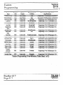
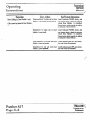
Station
Number
Circuit
Function
CConductor
Station Jack?
66-Block
Termhal
SO-Pin
Connector
25 Pair
Cable*
10
voice (tip)
voice (ring)
green GN)
red W)
1
2
26
1
white/blue
blue/white
data WP)
data (ha
black (BK)
yellow (YL)
3
4
27
2
white/orange
orange/white
voice (tip)
voice (ring)
green WO
red (RD)
5
6
28
3
white/green
green/white
data (GP)
data (ring)
black (BK)
yellow (YL)
7
8
29
4
white/brown
brown/white
voice (tip)
voice (ring)
9
10
30.
5
white/slate
slate/white
data WP)
data b-ha
gTeen (W
red WI
black (BK)
yellow (YL)
11
12
31
6
red/blue
blue/red
voice (tip)
voice (ring)
green (0
red (RD)
13
14
32
7
redorange
orange&d
data @PI
data(ring)
black (BK)
yellow (YL)
15
16
33
8
red/green
green/red
voice (tip)
voice (ring)
green (0
d(RD)
17
18
34
9
red/brown
brown/red
data (GP)
data w%)
black (BK)
yellow (YL)
19
20
35
10
voice (tip)
voice (ring)
green (GN)
.=d(RD)
21
22
36
11
black/blue
blue/black
data (GP)
data ww)
black (SK)
yellow (YL)
23
2A
37
12
black/orange
orange/black
11
12
1s
:.
14
15
’
l-d/Slate
slate/red
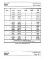
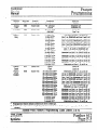
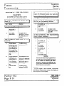
f Use mathing color codesfor the 4-amdnctor smion wiring cables.
* The first color listed is the predominant Color the second c&r listed is tbt tracex or seipe color.
Station Wiring Table (Sheet1 of 2)
,_i
TRILLIUM
Telephone
Systems
-
’ Panther- 6 12
Page D-3
Technical
Service
Manual
Connection
Procedures
Station
Number
Circuit
Function
4-Conductor
Station Jackt
66-Block
Terminal
SO-Pin
Connector
25 Pair
Cable*
16
voice (tip)
voice (ring)
25
26
38
13
black/green
green/black
data (tip)
data w%)
green (W
red (RD>
black (BK)
yellow (YL)
27
28
39
14
black/brown
brown/black
voick (tip)
voice (ring)
green (W
red CW
29
30
40
15
data (tip)
data (fig)
black (BK)
yellow (YL)
31
32
41
16
yellow/blue
blue/yellow
voice (tip)
voice (ring)
green WI
red WI
33
34
42
17
yellow/orange
orange/yellow
data (tip)
data @WI
black (BK)
yellow (YL)
35
36
43
18
yellow/green
green/yellow
voice (tip)
voice (ring)
green GN)
red WI
37
38
44
19
data (tip)
data 0-w
black (BK)
yellow (YL)
39
40
45
20
yellow/slate
slate/yellow
voice (tip)
voice (ring)
green GW
red (RD)
41
42
46
21
violet/blue
blue/violet
data (tip)
data (e%)
bhd 0
yellow (YL)
43
44
47
22
violet/orange
orange/violet
voice (tip)
voice (ring)
green GN)
red 0)
45
46
48
23
violet/green
greenhiolet
data (tip)
data w%)
black (BK)
yellow (YL)
47
48
49
24
violet/brown
brown/violet
17
18
19
20
21
’
.
”
black/slate
slate/black
yellow/brown
brown/yellow
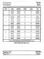
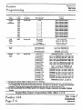
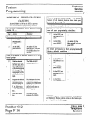
t Use matching color codesfor the 4umductor station wiring cables.
* The first color listed is the predominant color; the second color listed is the tracer or stripe color.
Station Wiring Table (Sheet2 of 2)
Panther 612
PageD-4
I
TRILLIUM 4”
Telephone
Systems
_
Connection
Procedures
:::;::::::::::::::::::::::
::::::::::::::::::::::::::::::::::::
::::::::::::::::::::..........................................................................................................................................................-..” ............................,
Technical
Service
Manual
......... .........*.............................*.....................................................................................- ....................- .........-.................,
:
STEP 4
CONDUCTING THE INITIAL
SYSTEM AND STATION TESTS
i
Lift the handset and press the line 2 key: dial tone
is heard; the Intercom indicator goes OFF; if
yours is a BLF Set, yout station indicator goes ON,
and the line 2 indicator WINKS slowly.
NOTES
j.
1. If the indications described below do not
occur, refer to the Troubleshooting section.
Hang up the handset: dial tone is removed; and all
indicators go OFF.
k
2.If the SMDR Interface unit is to be installed,
it should be installed prior to conducting these
tests. seestep 11. -
Repeat steps i and j for lines 1.3.4, and 5 - and
line 6 as well, if not used for the Door Answer
Unit
L
Repeat steps g through k for the remaining stations.
a
Connect the KSU power cord to the surge protector
previously installed at the 110 V ac power outlet:
the recessed STATUS indicator goes ON (with a
slight flicker) indicating that the KSU is operative.
b.
Set KSU switch 4 BATTERY to ON (if necessary,
use a paper clip or other pointed object such as a
pen or pencil to set the KSU miniature DIP
switches).
c
Set KSU switch 1 PROCRAM to ON.
d
Push the recessed RESET pushbutton once.
e
Set KSU switch 1 PROGRAM to OFF.
f.
Push the recessed RESET pushbutton again: the
system is now set the factory preprogrammed conditions (for details on what those conditions are, see
the Feature Programming section).
g.
At station 10, plug in the 4-conductor modular cord
supplied with the Set between the Set and the station wiring jack
h
Press the Set’s Intercom
key: the Set’s speaker
emits a continuous tone and theIntercom indicator
goes ON.
TRILLIUM
Telephone
Systems
Unless you have optional items to install (the Door Answer
Unit, the OPX unit, the SMDR Interface unit, the Power Fail
Transfer Unit, external paging equipment, a dry contact interface, or a music source), your Panther 612 Electronic Key
Telephone System is now ready for programming or
operation.
STEP 5
CONNECTING
THE BACKUP BATTERY
The KSU has a white plastic Molex connector at its top for
connecting an external backup battery. The backup battery
used (such as the TRI 24/2.5B from Alpha Technologies)
should provide 24 V dc at 2 Amps for an extended period of
time.
a
Connect the positive (+) terminal of the battery
(usually the red lead) to the left side of the KSU
connector.
b
Connect the negative (-) terminal of the battery
(usually the black lead) to the right side of the KSU
connector.
Once connected, switchover to the backup battery occurs automatically when power fails.
I
Panther 6 12
Page D-5
Technical
Service
Manual f’.
Connection
Procedures
I................................................
. . . . . . . . . . . . . . . . . . . . . . . . . . . . . . . . . . . ...”
. . . . . . . . . ::::::::::::::::::::::::::::::::::::::=”::::::::c::::::::::“”:::::::::::::::::::::::::::::::::::::::::::::~
:::::::::::::::::::::
STEP 6
CONNECTING
DOOR ANSWER UNIT
AND DOOR MODULES
NOTE
Door Module Installation
If you have chosen to install the Door Answer
Unit with its one or two Door Modules, line 6
must be left vacant
G Door Answer Unit Installation
a
b
Mount the Door Answer Unit on thi: backboard
along with the KSU, using the four screws supplied
with the equipment.
C%‘mect a 6-conductor modular cord (not supplied)
to the connector labeled DOOR on the KSU and the
connector labeled DA on the Door Answer Unit.
. .. .. .. .. .. .. .. .. .. . . .. .. I. . .. .. .. .. .. .. -““-
. .. . .-
. .. .. .. .. .. .. .. .. .. .. .. -..“““...“. ~
Panther 6 12
Page D-6
. . . . . . ...”
. . .. -
.y’:..z-
m
(,
z :::::::::::::::::::::::::::::::::::::::::::::::::::::::::::::::::::::::::::
.
a
Remove the screw securing the Door Modules’
front cover, and separate the front from the back.
h
Mount the backs of the Door Modules at the desired entryway locations, using the two mounting
screws furnished with each Door Module.
C.
RM a length (not to exceed 2000 feet) of 2conductor, 24 AWG wire from the Door Answer
Unit to each Door Module.
d
Feed the wire through the hole in the base of the
back of the Door Module.
e
Strip the cable end and secure it to the screw terminals found on the backside of the Door Module’s
fhnt assembly.
f.
Replace the Door Module’s cover and tighten the
screw to secure the front to the back.
g.
At the Door Answering Unit, strip the cable ends
and secure the cable from Door Module 1 to the
screw terminals labeled Dl and the cable from
Door Module 2 to the screw terminals labeled D2.
. . . ...”
. . . . . . . . . . . . . . . . . . . . . . . . . ...”
. . . . . . . . . ...”
. . . . “I..“.......-
“:::“‘“‘“.““::::::::““‘:::::“‘::::”:::
I
..:‘-...“::..~~““:““‘::
__
TRILLIUM 6
Telephone
Systems
..
Technical
Service
Manual
Cbnnection
Procedures
.__............
. . .._......
. . . . . . . . . . . . . . . . . . . . . . . . . . . . . . . . . . . . . . . . . . . . . . . . . . . . . . . . . .* .. .. .. .. .. .. .. .. .. .. .. .~.::::::::::::::~1:‘:::::::::::::::::::::::::::::::::::::::::~:::::::~::::::::::::::::::::::::::::::::::::::::::::::::::::::::::::::::::::::::::::::::::::::::::::::::::::
.
,...................................................................................
Door Answer Unit Test
NOTE
c.
Door Module 2-initiated calling:
i
At Door Module 2’s entryway, have someone
press the door button: four groups of 2 long
tones are heard at all Sets programmed to ring
on line 6; and the line 6 indicator FLASHES
slowly.
ii
At any Set, pick up the handset and press the
line 6 key: the line 6 indicator WINKS; if
yours is a BLF Set, your station indicator goes
ON: and you and the person at the entryway
are connected.
iii
At the Set, hang up the handset: all indicators
go OFF; and the call is terminatecL
If the indications described below do not
occur, refer to the Troubleshooting section.
a.
Door Module l-initiated calling:
i.
ii.
At Door Module l’s entryway, have someone
press the door button: four groups of 4 short
tones are heard at all Sets programmed to ring
on line 6; and the line 6 indicator FLASHES
slowly.
At any Set, pick up the handset and press the
line 6 key: the line 6 indicator WINKS; if
yours is a BLF Set, your station indicator goes
ON; and you and the person at the entryway
%Ct COMeCti
iii
f-
b.
At the Set, hang up the handset: all indicators
go OFF, and the call is terminated.
Set-initiated calling:
NOTE
Set-initiated door module intercom calls can
only be placed to Door Module 1, not to Door
Module 2.
.
c-
i
Alternatively, at any Set, pick up the handset
and press the line 6 key: the line 6 indicator
WINKS; if yours is a BLF Set, your station indicator goes ON, and the person at Door
Module 1 hears a burst of ringing. u
ii
At the entry way where Door Module 1 is instalkd, the person responds by speaking in the
direction of the Door Module: you and the person at the entryway are connected.
iii
At the Set, hang up the handset: all indicators
go OFF, and the call is terminated.
.. ...“..._LI.a.::
:::::::::D:::::::~
:::::
::::::::D.::::
:::::::
:::::::::::8::::;“‘::~~::.1:::...........I._._._...”
. ..”
. ..‘.......”
......,.
_““.......
..- ......“I
-..................... ......_......W.......“”
TRILLIUM
Telephone
Systems
’ Panther 612
Page D-7
“..*:::::::
::::::.
z:..”
~“‘~“~~:.;::“‘.~“.~:::.~:.~:~~~~..~~~~~.~~~~~~
-....-- ....:“:‘*:::::.
..::x:.?...
.....-a.......-.
......-......~:...:~~~~~
.-..““....._L_
::::::::::::::::::::::::::::::::::::::::::::::::::::::::::;:::::::::::::
:::::::::::::::::::::::~:::::::::::::::~::::::::::::::::::::::::~:::::::::::::~~::::::::::::::::::~....................
-, ...................................................................”..,................”
Technical
Connection
Service
Manual
Procedures
:::::::::::::::::::::::::::::::::::::::::::::::::::::::::::::::::::::::::::::::::::::::::::::
:::::::::::::::::::::::::::::::::::::::::~::::::::::::::::::::::::::::::::::::::
~‘~..“......‘~...“............................................
..,...........
P ......... ........................................................................... c
STEP 7
CONNECTING THE MUSIC SOURCE
Music Connection
a
Connect one end of the cable (not supplied) into the
music source’s output jack.
b.
Connect the other end, which terminates in a l/Sinch mini-jack @hono; not stereo or attenuator),
into the KSU connector labeled MUSIC.
c
Testing the background music on hold:
i
Have someone call in on outside line 1 (alternatively, you can call line 1 from line 2):
ringing is heard at all stations programmed to
ring on line 1; and the line 1 indicator
FIAsHEs slowly.
ii
At any station, pick up the handset and press
the line 1 Key: the line 1 indicator WINKS
slowly; if yours is a BLF Set, your station indicator goes ON; and a connection is made with
the outside caller.
Music Test
NOTE
iii. After informing the outside caller of your intentions, press the Hold key and hangup the
handset: the line 1 indicator FLASHES quickly. if yours is a BLF Set, yuw station indicator
goes OFF, and the outside caller hears the
bxkground music.
If the indications described below do not
occur, refer to the Troubleshooting section.
a
Turning background music on at a Set:
i
At any station, with the handset in its cradle,
press the Intercom Key: the Intercom indicator WINKS slowly; and a continuous tone is
heard over the Set’s speaker.
ii
With the handset still in its cradle, dial l 4: the
Intercom indicator goes OFF, and the continuous tone is replaced by background music
coming from the Set’s speaker.
iii
At the music source, adjust the level of the
background music for the desired loudness.
iv. After a few seconds, retrieve the calI by picking up the handset and pressing the line 1 key:
the line 1 indicator WINKS slowly; if yours is
a BLF Set, your station indicator goes ON,the
outside caller no longer hears the background
music; and the connection with the outside
CaIler is restored.
v.
b.
At any station, with the handset in its cradle
pressthe Intercom Key: the InterCOm indicator WINKS slowly: and a continuous tone is
heard over the Set’s speaker.
ii
With the handset still in its cradle, dial * 4: the
Intercom indicator goes OFF, and neither the
continuous tone nor the background music is
heard over the Set’s speaker.
. . . . . . . . . . . . . . . . . . . -..::~:::“‘::::::::::::::T’:::;:::::::::::::::~~:::::::::::::::~~~~:::~::::~~~~::::::::~~~~::::::::~::::::::::::
. . . . ...*.* . . . . . . . . -
Panther 6 12
Page D-8
_
Cmfirm the success of the background music
an hold test with the outside caller.
vi. I-bug up the handset: ail indicators go OFF;
and the call is terminated.
Turning background music off at a Set:
i
.
:::::::::::::::
::: -~::::::::~::::::m::::::::::::::::::~:::::::~:::~~~:::::~:~
I
_
TRILLIUM c
Telephone
Systems
Technical
Service
Manual
Cdnnection
Procedures
.............................................*....................................................
..............._.....
::::::::::::::::::::::~::::::::::::::::::::
:::::::::::::
STEP 8
CONNECTING
THE EXTERNAL
PAGING EQUIPMENT
Equipment Connection
STEP 9
CONNECTING
AN EXTERNAL LOUD BELL
Equipment Connection
a
Connect one end of the cable (not supplied) into the
external paging equipment’s input jack.
b.
Connect the other end, which terminates in a I&
inch mini-jack (phono, not stereo or attenuator),
into the KSU connector labeled PAGE.
Connect a 2conductor cable between terminals 49 and 50 of
the 66-block (the violet/slate pair in the 25pair cable) and
an external dry contact interface unit, such as the Wheeloch
model 24-24 (not supplied). Connect an external loud bell or
other sounding device to the dry contact interface unit.
Loud Bell Test
NOTES
Paging Test
1. If the indications described below do not
occur, refer to the Troubleshooting section.
NOTE
If the indications described below do not
occur, refer to the Troubleshooting section.
a
At any station, pick up the handset and press the
1nterCOiII
Key: the Intercorn indicator WINKS
slowly; if yours is a BLF Set, your station indicator
goes ON; and a continuous tone is heard.
Cb.
,-
(
......
“.
...
Make a test announcementz the test announcement
is heard over the external paging loudspeaker.
d.
Hang up the handser all indicators go OFF; and the
external paging loudspeaker falls silent.
-
3. See Feature Programming for details on how
to program the loud bell.
Dial 69: a double tone burst is heard over the external paging loudspeaker.
c
..“.
...
.
.......
2. The factory preprogrammed condition for
the loud Ml is both day and night bell. If you
are installing a new system, the loud bell
should ring on all incoming calls.
..
..-.....”
TRILLIUM
Telephone
Systems
.“.
.
.......
..I..
--...
.
.
..-.
.
........
.........
-..-.I
.
.
.
I..
..-.I
................
.
..........
_.I_
‘....................“.......
..I..
.....
--.-.
-.
.....
.....
..”
-.
-.........-I
.........
a
Have someone call in on outside line 1 (altematively, call line 2 from line 1): the line 1 indicator
FLASHES slowly; and the external loud bell rings.
h
At any station, pick up the handset and press the
line 1 key: the line 1 indicator WINKS slowly; if
yours is a BLF Set, yaw station indicator goes ON;
a connection is made with the outside caller; and
the loud hell stops ringing.
d
Hang up the handset all indicators go OFF; and the
loud bell remains silent.
...........
“_...”
“._
..“.
...
.v
--.
-.:::“:::::~:::::::::::r
.
.
.
.....
....
___.I
.._...I..
.
’ Panther 6 12
Page D-9
Connection
Procedures
Technical
Service
Manual
. . . . . . . . . . . . . . . . . . . . . . . . . . . . . . . . . . . . . . . . . . . . . . . . . . . . . . . . . . . . . . . . . . . . . . . . . . . . . . . . . . . . . . . . . . . . . . . . . . . . . . . . . . . . . . . . . . . . . . . . ...............................................................
. . . . . . . . . . . . . . . . . . . . . . . . . . . . . . . . . . . . . . . . . . . . . . . . . . . . . . . . . . . . . . . . . . . . . . . . . . . . . . . . . .**.a.*
. . . . . . . . . . . . . . . . . . . . . . . . . . . . . . ...”
. . . . . . . . . . . . . . . . . . . . . ...
STEP 10
CONNECTING THE OPX UNIT
OPX Unit Connection
NOTES
_ _.........._......._.......................................................
...........................,,........-........-........................,.................,....................
:::::
OPX Unit Test
NOTE
If the indications described below do not
occur, refer to the Troubleshooting section.
a
1. The OPX unit may be installed at any station
location - except station 10.
Originating internal calls:
i
2. See also Typical System Layout Diagram on
page E-2
At the standard set connected to the OPX unit,
pick up the handset: a continuous tone is
heard.
Call another station by dialing its 2digit number, such as 13: at the called station, repeated
long tones are heard.
Mount the OPX unit next to the desired station location, using the four screws supplied with the
equipment
ii
b. Plug the small dc connector into the OPX unit‘s
POWER connector and plug the wall connector
into an unswitched, grounded 115 V ac outlet.
iii
c
iv. Hang up the handset to terminate the call.
a
Connect the modular cord (not supplied) between
the station wiring jack and the KSU jack on the
OPX unit
NOTE
h
Alternatively, the remote device can be accessed through a CO line (with no limits on
distance). FCC rules require that you tell the
telco that the OPX‘s Facility Interface Code is
OL13B and its Service Code is 9.OF.
c
In either case, the 2conductor cord in step d
will then be connected between the RJll jack
and the TEL jack on the OPX unit
Connect a 2conductor cord between the TEL jack
on the OPX unit and the 2-line device to be used
(such as a standard set, answering machine, or
modem).
e
If access to an outside line is desired in the event of
a power failure, connect a spade-to-modular, 2conductor cord between one of the incoming lines
(in parallel with the normal system connection) and
the PFT jack on the OPX unit.
f
Set the A-B switch on the OPX unit to B.
-Panther
---- 6 12
;e D-10
pag
“::::::::::::::::::::~~::::::::::::::::::::~~:::::::~::::::::::~~~:::::~.~~~-:~::.~..-
UI
. . . . . . . . . . . . . . . - .-................”
. .. . .. .. . .. . ... .
. . . ...“...“”
The called party picks up the handset: the tones
stop; and you and the called party are
connected
Receiving internal calls:
i
Have someone place an internal call to the station at which the OPX unit is installed: your
setrings.
ii
Pick up the handset the ringing stops; and you (
and the calling party are connected.
iii
Hang up the handset to terminate the call.
_
If the device to be used is remotely located
(not to exceed 2 miles on a direct connection),
a 2conductor, RJl 1 jack can be mounted and
wired to the remote device.
d
f
Placing outside callsz
i
At the standard set connected to the OPX unit,
pick up the handset a continuous tone is
heard
ii
Request outside line 1 by dialing '01: an externaldialtoneisheard.
iii
Complete the outside call by dialing the desired number. Hang up, when finished, to
teminate the call.
iv. Test access to outside lines 2 through 5 and
outside line 6 (unless the optional Door
Answer Unit is installed) by -repeating steps I
through ti above for outside lines 2 through 6.
. ...”
. . .._...........
. . . . . . --
. . . . . . . . m -::::::m:::i”:“:D.
I
w...
. . .. .. .. .. . . . . . “..‘.....w
. . . . . “....
.. . .. . .
TRILLIUM (-Telephone
Systems
Cbnnection
Procedures
Technical
Service
Manual
. . . . . . . . . . . . . . . . . . . . . . . . . . . . . . . . . . . . . . . . . . . . . . . . . . . . . . . . . . . . . . . ” . . . . . . . . . . . - . . ...”
,.....“...............
a.. . . . . . . . . . . . . . . . . . . . . . . . . . ...”
. . . . . “”
. . .. .. .. .. . .. .. .. .
. . .. . . .. .. .. .. . . .. .. .. .. .. .. .. .. .. .. .. .. .. .. . . .. . ..I..I
. .. .. .. .. .. .. . . .. . . .. . . .. .. .. .. .. .. .. .. .. -..............................................................................““.........................................................
. . . . . . . . . . . . . . . . ...”
. . . . . . . . . . . . . .....”
................................-......,”
STEP 11
CONNECTING
THE SMDR INTERFACE UNIT
(part number 90-0169 only)
NOTES
*..*
................”
.....,
Connect an RS-232 cable between the connector at
the bottom of the SMDR Interface unit and the
recording device (terminal or printer).
d
Set the appropriate baud rate switch (300,600, or
1200 bps) on the SMDR Interface unit top match
the requirements of your recording device.
e
Set the BATTERY switch on the SIvlDR Interface
unit to ON.
f
If not performed already, go to Step 4 to apply
power to the system and to conduct the initial system tests. When Step 4 is completed, return and
perform the SMDR Interface unit test procedure
(found below).
1. At a minimum, pin 3 (Received Data) and
pin 7 (Signal Ground) must be wired in the
cable connecting the SMDR Interface unit and
the recording device.
2. Also, depending on the characteristics of the
recording device, other pins may need to be be
jumpered, grounded, or raised - consult your
recording device’s technical manual or your
recording device manufacturer’s customer
service.
......
c.
CAUTION
Power should not beapplied to the KSU when
installing the SMDR Interface unit.
........”
SMDR Interface Unif Test
NOTE
The time of day, date, month, and year are all
programmed into the SMDR from station 10.
See the Operating Instructions section.
3. See also the specifications on page C-l and
the Typical System Layout Diagram on page
E-2
a
Place an outside call: verify that the call information is recorded, as shown below.
h
Have someone place an incoming call and -during
the incoming call - enter an account number (see
Opeming Instructions section): verify that the call
information and account number is recorded, as
shown below.
SMDR Interface Unit Installation
a
Mount the SMDR Interface unit below the KSU on
the plywood backboard.
b.
Connect the special ribbon cable (supplied with the
SMDR Interface unit) between the connector at the
bottom of the KSU and the connector at the top of
the SMDR Interface unit.
Typical Outgoing Call Format (all recorded on one tine)
[month]/[date]
07/23
[time
of day]
02:25P
[length
of call1
00:02:24
[station]:
014
[not
used]
[telephone
000
number]
[outside
17145573300
~~~
line]
[account]
TOO1
Typical Incoming Call Format (all recorded on one line)
[month]/[date]
07/23
“::
~:“~::~:::::::::::::::::::“::::“:::::
[time
of day]
03:22P
[length
of call]
[outside
line]
: . . .- -“ “ “ “ . & : : - . . .
. .
P.........
/-
\
TRILLIUM
Telephone
Systems
[seconds
to answer]
[station]
00:11:53
TOO3
029
SMDR Printout Formats
.
. -
.
.
. .
. .
.
. . .
. m”
~.“....“-.“.........“..-.”
. .
.
...”
011
.
. .
. .
. _.”
..“....__.......-
[account]
Al234
-.~::::.-:::~::“.
.
. .
...”
’ Panther- 6 12
Page D-11
::::
:::::::::::::::::::
~~
:::::
:: :::::::::::::
:::::::::::::::::::
;‘:“::“:::
:::::-::::
:’ . . . . . . . . . . . . . . . . . . . . . . . . . . . . . . . . . . . . . . . . . . . . . . . . . . . . . . . . . . . . . . . . . . . . . . . . . . . . . . . . . . . s . . . . . . . . . . . . . . . . . . . . . . . . . . . . . . . . . . . . . . ...........................................................
. .. .. .
. . . . . . . . . . . . . . . . . . . . . . . . . . . . . . . . . . . . . . . . . . . . . . . . . . . . . . . . . . . . . . . . . . . . . . . . . . . . . . . . . . . . . . . . . . . . . . . . . . . . . . . . . . . . . . . . . .............
. ..............................................
Technical
Connection
Service
Manual
Procedures 1::::::::::::::::::::::::::
“‘:::::
:’..................................................................-.”...........................-.................................................
.....,................-........::::::::::::::::::::::::::::::::.
......a
............................................................. . ........................................“...”.,..........”
...................................
c
......................-.,
STEP 12
CONNECTING THE
POWER FAIL TRANSFER UNITS
NOTE
d
Route the incoming lines to the Power F&l Transfer
units:
Perform the following procedure only if you
wish to install the optional Power Fail Transfer
Unit If such is the case, then this procedure
should be followed in liei @Step 2.
i
Connect a 4conductor modular cord behveen
the single RI14 jack at which incoming lines 1
and 2 are terminated and the 1st Power Fail
Transfer Unit jack labeled C01.2.
ii.
Connect a 4-conductor modular cord between
the single RJ14 jack at which incoming lines 3
and 4 are terminated and the 1st Power Fail
Transfer Unit jack labeled C03.4.
iii.
Connect
a 4-conductor modular cord between
the single RJ14 jack at which incoming lines 5
and 6 are terminated and the 2nd Power Fail
Transfer Unit jack labeled CO12
CAUTION
Power should not yet be applied to the KSU.
Power Fail Transfer Unit Installation
NOTE
See also the Power Fail Transfer Unit diagram
in the System and Set Layout section.
a
Mount hvo Power Fail Transfer Units in the upper
right corner of the plywood backboatd
b.
Connect the 2-conductor special cable supplied
with the 1st Power Fail Transfer Unit, as follows:
.
c
i
At the KSU, connect one end of the special
cable to the connector labeled KWER FAIL.
ii
At the 1st Power Fail Transfer Unit, connect
the other end of the special cable into the connector labeled CNK
e.
Route the lines from the Power Fail Transfer Units
totheKSU:
At the 1st Power Fail Transfer Unit, connect
one end of the special cable to the connector
labeledCNJ.
ii
At the 2nd Power Fail Transfer Unit, connect
the other end of the special cable into the connector labeled CNK.
. . . . . . . . . . . . . . . . . . . -“,
. ..” . . . . . . . . . . . . . . . -
. . . . . . . . . . . . . -“”
. . . . . . . . . . . “.......I..“...”
. .. ..
. . . . . . “...-............ . . . . . “-
Panther 6 12
Page D-12
.“-
-~:~::y;::::::““:~y-.
. . . . . . . “..:““:.::::y.:..z
Connect a 4-conductor modular cord between
the 1st Power Fail Transfer Unit jack labeled
TK1.2 and the KSUjack labeled C01.2.
ii
Connect a 4-conductor modular cord between
the 1st Power Fail Transfer Unit jack labeled
TK3.4 and the KSU jack labeled C03.4.
iii
Connect a 4-conductor modular cord between
the 2nd Power Fail Transfer Unit jack labeled
TK1.2 and the KSU jack labeled C05.6.
f.
Install six stwzdurd telephones (2-wire sets) in convenient cr strategic locations.
g
Using 2-conductor, modular cords, connect the
stat&xl sets to the jacks labeled TIT through T4T
on the 1st Power Fail Transfer Unit and to the jacks
labeled TlT and T2T on the 2nd Power Fail
Transfer Unit.
Connect the 2-conductor special cable supplied
with the 2nd Power Fail Transfer Unit, as follows:
i
i
::::
“m
. . . . . . . . . . . . . . . . . . . . . . . . “. . . . . . s... . . . . . . . . . . . ““I”
. . . . . . . ...”
. . ..-.“-__l
. . . . . . . . . . 1...1....1-...“e.“”
I
. . .. . .. ..
..-“...
. . .. .. .. .. .. .. .“. . .
TRILLIUM
fff
Telephone
Systems
.’
Technical
Service
Manual
Connection
Procedures
...................................,........,....................................,...........
...........................-.
........................................ .................................
............................................................................................................................................
...................................,.........
...*.................................................................... ..........................................................................................
Power Fail Transfer Unit Test
“I’:::::&...“.....“..“.
a
With power still removed from the KSU, the standard sets just installed should all be receiving dial
tone - and be able to originate and receive outside
calls. If not, refer to the Troubleshooting section.
b.
ProceedtoStep3..
.
..-........-......................................... . . . . . . . “.....
TRILLIUM
Telephone
Systems
. . . . . . “....I.“.“-
-
. .. . .. .. .. . ... . ..““Y.............”
. . . . C........------.
. .
.
. ... . .. . .. .. .. .. .. .. .. . .. . . .. .. .. .. .. .. .
.. .. .. ..
. ..I . . . . . . . . . . . . . “..““.......“.....“...a-
. .. .. .
. . . . . A.....“..._
..I._
. .. . .. .. .. .. .. .. . .. . .. .... . ..
. ...“” . . . . . . . “-”
... . .. . ... .. I
. . . . . . . . ...”
. .. .. a
. . . . . . . . . . . ...* . . ..I..
. . . . . . . . . . . ..I..
. . . . . . . . . . . *.
’ Panther. 6 12
Page D-13
Technical
Service
Manual f
Connection
Procedures
STEP 13
INSTALLING
AN EXTERNAL
AMPLIFIER/SPEAKER
If an external amplifier/speaker is to be installed at a given
station, the the standard station wiring and Set installation
procedures must be modified for that station as follows (see
also the diagram to the right):
a
Instead of mounting a ll-conductor RJ14 jack at the
station location (see Step 3 b), mount a 6-conductor
RJ25 jack.
NOTE
The 4conductor station wiring cable between
the 66-block terminals and the station wiring
jack still follows the details given in the station
wiring table on pages D-3 and D-4 - with the
4 wires still running from the same 66-block
terminals and being installed color-to-color on
the jack, green-to-green, red-to-red, black-toblack, and yellow-toyellow.
h
Connect the external amplifier to the blue and
white terminals of the RJ25 station wiring jack
c
Instead of using the 4-conductor modular cord supplied with the Set (see Step 4 g), use a standard 6conductor modular cord to connect the Set to the
station wiring jack.
L
Connect Set
by Plugging
6-conductor
modular cord
in here
NOTE
The external amplifier/speaker is now connected to the Sets speaker terminals.
..............
...
. . . .
.
d
Check to see that signaling and voice messages
normally heard over the Set’s speaker will now be
heard over the external amplifier/speaker.
e
To return the Set to its normal operation, simply replace the 6-conductor cord between the Set and the
station wiring jack with the 4-conductor that was
originally supplied with the Set.
....
..
_.I..
..“.
..
.......
M....
.
.
..:::::“:::-‘::::::::
.
Panther 6 12
Page D-14
:::::
::::::::::::::::::::::::::::::::::::::::::::::::::::::::::::::::::::::::::::::::::::::::::::::.~~:::::::::::~:::::::
1
“.
..-.
.............
. --.
..-...
....................................................
/-
TRlLLiUM c,
Telephone
Systems
/
Technical
Service
Manual
System and
Set Layout
12AW
ww
wife
c/
Power cord
4-conductor
66-b&k
IONS 10 TO 21
LOUD BELL
RJ14
KSU
RJ14
-.
HandsfreeIBLF
Set
TYPICAL SYSTEM LAYOUT DIAGRAM (Standard Components only)
(-
TRILLIUM
:::::::::^“:::::::“:::-~~~~.::::”:::~:::~:::::::::::::::::::::.~:::::::::::::::::::::~~~:~~::::~.::::::~~~:::~~:.~:~::::~::::~:::::::::~
~~.:~~“;~~.~“““““:“:“===::~-::~::::~~.-~:~~~
::::
::::;;
::::
‘Panther 6 12
Page
E-l
:::::::::::.~::::::::::::~~~~:::::::::::::::::::::::::::::::::::::::::::~::~::::::::::::~
:::::
““I:::::::
i-.::.~
:::::::::
::::::::::::::::::
Telephone
Systems
......................................‘...........................................................................................................................................
............ ...... ..... ...... ....., ...................... ............._.... ...... .._........................................... ::::::::::::~1:::~:
.....................................................................................................................................................................................~~
Technical
System and
Service
.Set
.........Layout
.............................................................................._.
......_.
..._
................_.
.._._
......Manual
...
,...............................*........................................................................................ c ;,
~~~~.~.~~~j::~,~j:~:~~
To earth ground $
qc.qz;.**;j$$$::g:.’
. . . . . . . . n..........................
#
I
. . . . . . . . . . . . . . . . . . . . . . . . ..i_...............
... .
~.:.~:.~~:.:.~.~.!.~.~.....
12AWG
..A _ ..... ... .... ... .... .... ... \
-$
D
source
$
s.....s........-----A
iF2.
66-block
DOO-R I
1 11 g1 equipmenl
pagingw
7
UD BEL
61Special cable
RJ14 I
OPX Unit
2cnnr-h
r&-w
TYPICAL SYSTEM LAYOUT DIAGRAM (Optional and External Components only)
. . . . . . . . . . ..-..........
“..
.. . .. ... . .. .. .. .. . ..
. . . . . . . . . . . . . . . . . . , . . . . . . . . . . . . . . . . . . . . . . . . . . . . . . . . . . . . . . . . . . . . . . . . . . . . . ..-.-.
. . . . . . . . . . . . . . . . . . . . . . . . . . . . . . . . . . . . . . . . .............-....................-..........-....-......... . . . . . . . . . - . . . . . . . . . . . . . . . . . . . . . . . . . . . . . . . . . . . . . . . . . . . . . . . . . . . . . . . . . . ..-.....-....................................................-...............................-.......
Panther 6 12
Page E-2
......................................................................................................--.....
-- ..................................
”
.
. . . . . . ...-”
”
........”
. . . ...”
.....__...__..
. . . . . .._...._.
TRILLIUM
@
“”
,f
Telephone
Systems
.............................................................................................................-....................................................-...................................
...........*......- ...............I..-...............”..._........_”
...”....”.._._”
.....................”
.........”
.......-........
Technical
Service
Manual
t
f
88
$
System and
Set Layout
Incoming
lines
5 and 6
I
1st Power Fail
KSU
RJ14
1 To
,;
other
4$ standard
sets
Standard Set
TYPICAL POWER FAIL TRANSFER UNIT LAYOUT DIAGRAM
._.............._._.-.......................-.
._.............._._.-.......................-.
“................. ...........
“......
-.I”
-.I”.
f’
. ..............
. . . . . . . . . . . . . .......
. . . . . --..I
TRILLIUM
Telephone
Systems
*...*...-.-...-..A
..I
.-
...
---..
. . .................
. . . . . . . . . . . . . . . ..-..
.. .
. . . . . II....
...
.....
--.
.... I....
I . . ..............................
..I.
.. .. . . .. . . .--. . . s .. .......
. ...... . . .
.............
. .. .. .. .. .. .. .. .. .. .. .. . ........
. . .. . . .. II..
-
. . .................................
.. ...”
.. .. .. .. .. .. .. .. .. .. .. .. .. .. .. .. .. .. .. . .. --.
. ..“.
. . . . .. .....................
. .......
p
........ . . .. . . .-”-“.___
.”. ........
. . .. -..-..-__
. .......
.. .. .. .. .. “.“.-
d
::::::::.::
::::::::.::
:=“::“::::::
:=“::“::::::
’ Panther% 12
Page
E-3
.........
::.=;;;:i::;:::::::i~.~:::“:::::::::::~
..-.“.-.
.....
I........
..........................
..............................
....................................
^......
..--..-.
........
....
..“.
....
.......
”-.
.........................
. . .......
.--- ....
....-.....
........
..”......
.._.....
“___
-.............
....“.
...___
.-... ...,
............
...............
Technical
System and
Service
Manual
Set
Layout
:::::::::
:::::::::
:::::::::
:::::::::::::::::::::::::::::::::::::::::::::::::::::::::::::::::::::::::::::::::::;::::::::::::::::::::::::::::::::::::::::::::::::::::::::::
::::::::
~~~~~~~~~.........................................
.............*............................................................... c._ :
\
119. Hold Ke!
[iii%]
Jiizp$]
16. Redial Key 1
I
20. Ringer
Volume
Switch
15. Direct
Station Select
(DSS)/Speed
Dial Keys &
Indicators
[ 1. Speaker
4
‘I
2. Speaker
Volume
Control
I
I13. Conference
I
Ke
3. Speaker
Key
12. Intercom
Key & Indicator I
II
4. Jacks for
Handset
Cord A
1 5. Handset 1
Cord
J
I
k
I
1
6.
--k-J
I.
SET LAYOUT
.. .. . .. . . . .._
J
DIAGRAM
.w......................
e . . . . . . . . . . . . . . . . . . . . . . . . . . . . . . . . . . . . . . . . . . . . . . . . . . . . . . . . . . . . . . . . . . . . . . . . . . . . . . . . . . . . . . . . . . . . . . . . . . . . . . . . . . . . . . . . . . . ........................................................................~
. . . . . . . . . . . . . . . . . . . . . . . . . . . . . . . . . . . . . . . . . . . . . . . . . . . . . . . . . . . . . . . . . . . . . . . . . . . . . . . . . . . . . . . . . . . . . . . . . . . . . . . . . . . . . . . . . . . . . . . . .....
. ....................-..................,.............,.............................-
I
_
..___............._......
_ _._.......................
..
TRILLIUM c
Panther 6 12
Telephone
Systems
Page E-4
.,...
......- .........“I
...........................................I.......
.....................,........................................................................................................................................
__.....................
.......................................................................................
~ .._........................
Technical
Service
Manual
System and
Set
Layout
.
.
.
.
.
.
.
.
.
.
.
.
.
.
.
.
.
.
..I....
.
.
.
.
.
.
.
.
.
.
.
.
.
.
.
.
.
,
.
.
.
.
.
.
,
.
.
.
.
.
.
,
.
.
.
.
.
.
,.
.
.
.
.
.
.
,
.
.
.
.
.
.
,
.
.
.
.
.
.
,
.
.
.
.
.
..,.
........_.......
..^
....
...........................-..-............
I...
........
... ......................
........................
............
I...................................
SET LAYOUT
1. The speaker allows the user to monitor the progress of
outside calls - and, with the Handsfree/Busy Lamp
Field (HWBLF) Set (as illustrated), to operate in a handsfree (speakerphone) mode. The speaker may also be
used to listen to background music, when available, on
both non-ha&free and handsfree Sets.
2. The speaker volume control (not labeled) adjusts the
loudness of sounds emitted by the speaker.
3. The Speaker key is used to turn the Set’s speaker on
and off - and, with handsfree Sets, to conclude a hands6ee call.
With handsfree Sets, in auto line, the Speaker key selects CO line; in auto intercom, the Speaker
key
selects intercom (see Manual/Auto Select feature).
4. Two jacks (one on the base of the handset and the other
on the left side of the Set) accept the plugs on the handset cord supplied with the Set.
5. The handset cord (supplied) connects the handset with
the Set.
,
6. The handset transmits and receives voice signals.
7. The line keys (1 through 6) select the indicated outside
lines (unless programmed differently), and the corresponding indicators show the status of the outside lines.
The keys and indicators are also used in feature
programm~g.
NOTE: Line 6 is used for door answering, rather than as
an outside line, when the Door Answer Unit is installed.
8. The tone dial pad is used in making calls and feature
programming.
In addition, two of the.se keys -when diiled first with
the handset in its cradle - have special operating
significance:
# automatically selects the internal intercom line.
automatically selects the last outside line used at
yourset.
l
9. The microphone detects and amplifies voice conversation to enable handsfree operation (not present on nonhanm
Sets).
s. : TRILLIUM
Telephone
Systems
10. The Speed key is used to dial common speed call
numbers; it also used to enter both private and common
speed call numbers into system memory.
11. The Mic.on/off key turns the Set’s microphone off and
on. The indicator goes ON (lights) when the microphone is turned on; the indicator is also used in feature
programm%.
12. The intercom key and indicator are used together or
independently in setting the Do Not Disturb feature,
making All Page, Zone Page, and other intercom calls,
monitoring rooms, and activating the Barge-In feature.
They are also used in’ feature programming and setting
the cal! detail record (CDR) clock.
13. The Conference
key sets up 3-party calls.
14. The Flash/Cancel
key is used as either a precise length (programmable) hookswitch flash or as cancel
key- but not both:
As a hookswitch flash, it is used for accessing
PBX, CENTREX, and other network features.
As a cancel key, it terminates external calls in
progress and returns a dial tone to the user - without having to hang up the handset.
15. The station select&eed dial keys are used for selecting
the indicated internal stations - and, except for the top
key (see 16, below), for dialing private speed call
numbers.
The indicators show the status of the other system stations but appear only on HF/BLF Sets.
16. The Redial key redials the last number manually dialed
ti-om your Set and serves as the key for station 10.
17. The plastic cover (Face Plate) protects the Designation
Card, which is used to keep track of private speed call
numbers and station assignments. HF/BLF and nonhandsfree sets use dzferent Designation Cards and Face
Plates.
18. The station wiring jack is used to connect your Set to
the station wiring; use the modular cord supplied with
your Set.
19. The Hold key is used to place calls on temporary hold.
20. The ringer volume switch is a 3-position slide switch
used to control the loudness of ringing at your Set.
I
Panther -612
Page E-5
. ...... ..._....--. - ._.........
Technical
Service
Manual
Feature
Programming
),...........................................................................
...._
..........................................................*.........*...........- .............................................
..........................”
...._.”
....
~.......
__...........
FEATURE CATEGORIES
You may program five different categories of features on
your Panther 612 Electronic Key Telephone System: system-wide features that apply to all sets and all lines, such as
Hold Recall Time and Auto Hold; individual Set features
that apply only to selected stations, such as Ringing
Assignments and Night Transfer Ringing; individual line
features that apply only to.selected lines, such as Tone or
Pulse dialing and Loud Bell Ringing; individual group features that apply only to selected groups, such as Line
Grouping; and, finally, speed call numbers divided into 34
common speed call numbers (codes 20-53), available at all
Sets, and 11 private speed call numbers, unique to each individual Set.
System-wide features, individual Set features, individual Set
features, individual line features, individual group features,
and common speed call numbers can only be programmed
from the Set assigned as station 10.
Individual speed call numbers, on the other hand, may be
programmed by Set users from their own individual Sets.
c
Categories Versus Codes
Programmable fcaturcs are assigned to program codes - and
sometimes more than one feature is assigned to a given program code. For example, the Hold Recall Time and Loud
Bell programmable features are both assigned to program
caieoom
Programming all features that have the same program code
ut the same time is an efficient way to program the Panther
612 Electronic Key System when it isjirst installed.
However, as system requirements change, programming
only the individual feature or features that need modification
becomes the most straightforward approach.
The feature programming procedures and tables in this section are organized by feature category and, within each
category, aQhbeticaliy by feature name - not numerically
by program code. (The feature descriptions located at the end
of this section are arranged simply in alphabetical order by
feature name-) Thus, all these materials are designed to support system changes, rather than system installation.
Referencing Categories to Codes
However, to help during system installation, a table - organized by program code numbers - is provided on the next
two pages, that provides references to the feature programming procedures, feature programming tables, and feature
descriptions that make up the balance of this section.
Interrelated Features
Moreover, as listed below (in program code sequence within
each group), certain features are directly or indirectly interre
lated (features not listed in any group below are judged to be
relatively independenr of other features).
Whenever you program or reprogram one of the features in
one of these interrelated groups, you should consider whether
a corresponding change is required to the other features found
in the same group.
Behind PBX/CENTREX-Related
Features
Flash or Cancel (OOll), Pause on Number (0020). Pause
Time (OOSO), Flash or Cancel Duration (0060), and
Telephone or PBX Line (5xX0)
Group-Related
Features
Line Group Type (0011). Line Group Assignment (3YYO).
and Line Grouping (6ZZO & 6ZZl)
Hold-Related
Features
Auto Hold (0001) and Hold Recall Time (0000)
Restriction-Related
Features
Digits-to Deny (0051). Call Restrictions (1YYl). Barge-In
(4YYO). Incoming Calls Only (5xX0), and Flexible Call
Restrictions (7OOO-7900)
Ringing-Related
Features
Loud Bell (0000). Ringing Assignment (2YYO & 2YYl),
Night Transfer Ringing (4YYO), and Loud Bell Ringing
mm
SMDR-Related
Features
Account Code (0001). Start Data Recording (0061), and
Interdigit Timing (0070)
-.
Tone/Pulse-Related
Features
Interdigit Pause (OOIO), Pulse Rate (0010). Make-Break
Ratio (0010). Tone Duration (OOll), and Tone or Pulse
mm
---_
TRILLIUM
Telephone
Systems
’ Panther 612
Page F-l
Technical
Feature
Service
Manual
Programming
..::::::::::::::::::::::::::::::::::::::::::::::::::::::::::
:::::::::::::::::::::::~
..................................-..........................................................
::::::::::::::::::::::::::::::::::::::::::z..
.................................................................................................,........................,.....
............. c
Preprogrammed
Condition
Feature
Name
Program
Code
Feature
Category
Common (20-53)
None
speed calling
None
Programming: F-WDescription:
see Section G
Private Numbers
None
speed cdling
None
Programming: F-19pkscription:
see Section G
Hold Recall Time
0000
System-wide
No recall
System-wide
Day and night bell
Programming: F-4 & F-7/Description: F-20
Loud Bell
’
Programming and Description
Page References
Programming: F-4 & Fd/Description:
F-20
Account Code
0001
System-wide
No printout
Programming: F-4 & F-S/Description: F- 19
Auto Hold
0001
System-wide
No auto hold
programming: F-4 & F-S/Description: F- 19
hbnual/Auto
Select
0001
System-wide
Auto intercum
Programming: F-4 & E7/Dtxription:
F-21
Interdigit Pause
0010
System-wide
800 milliseconds
Programming: F-4 & F4Description:
F-20
Make-Break
0010
System-wide
40%
Programming: F-4 & F-7/lkscription:
F-20
Pulse Rate
0010
System-wide
10 pulses per second
Programming: F-4 & F-8/Description: F-21
Flash or Cancel
0011
System-wide
Cancel
Programming: F-4 & F-S/Description: F-20
Line Group Type
0011
System-wide
Programming: F-4 & F-7/Description: F-20
Tone Duration
0011
System-wide
Type A
100 milliseconds
Programming: F-4 & F-8/Description: F-21
Pause on Number
0020
System-wide
No pause
Programming: F-4 & F-7/Description: F-21
PauseTiie
0050
System-wide
3 seconds
Programming: F-4 & F-8/Description: F-21
Digits-to-Deny
0051
System-wide
8th digit
programming: F-4 & F-S/Description: F-19
FlashorCancel
Duration
OO60
System-wide
1 second
Programming: F-4 & F-S/JXscription: F-20
StartData
Recording
0061
System-wide
5 seconds
Programming: F-4 & F-8/Description: F-21
Interdigit Timer
0070
System-wide
10 seconds
Programming: F-4 & F4/Description:
Ratio
-
F-20
Feature Programming Cross-ReferenceTable (Sheet 1 of 2)
......................
..........
. ...........
m..
-.
.. .......
.... “.“S..
-.
......
....
.
.
........
.........
Panther 6 12
Page F-2
-.
.
.........
............
-.
“...
.......
. .... .-..I
I.. .... . . ...+. . .-
......
.....
---.
.
....
....
“”
. . . ......
.........
F
B..
......
. ..I..
. .......
......
..”
. ........
. .........
.
““.._...
.....
I--.
......
............
-.
.......
......
I
--..-..-..-.. ......
“..“........
-
.-.
.........
. .....................
“.._
.
..” -
fl
TRILLIUM 6
Telephone
Systems
..
Technical
Service
Manual
?
Feature
Name
Program
Code*
Feature
Category
Call Restrictions
lYY1
Individual Set
Class A
Ringing
Assignment
2YYO
@art 1)
2YYl
Individual Set
(linesOl-04)
No ringing*
Programming: F-10 & F-l l/Description: F-21
Individual Set
(lines 05 & 06)
No ringing+
Programming: F-10 & F-l l/Description: F-21
@=t2)
Line Group
Assignment
3YYO
Individual Set
No group
-Programming: F- 10 & F- 1 l/Description: F-20
Zone Paging
3YYl
Individual Set
No zones
Programming: F-10 & F-1’UDescription: F-21
Barge-In
4YYO
Individual Set
No barge-in
Programming: F-10 & F-l l/Description: F-19
Night Transfer
Ringing
4YYO
Individual Set
No ringing
Programming: F-10 & F-l l/Description: F-21
Incoming
Calls Only
5xX0
Individual line
No
Loud Bell
Ringing
5xX0
Individual line
Ring
.
Programming: F- 14 & F- 1S/Description: F-20
Telephone or
PBX Line
5XXo
Individual line
Telephone
Programming: F-14 & F-lS/Description: F-21
Tone or Pulse
5XXo
Individual line
Tone
Programming: F-14 L F-15Desaiption:
F-21
Line
Grouping
&ZO’
(part 1)
6221
Individualgroup
(lines 01 - 04)
AUliies$t
Programming: F-16 &F-17/Description:
F-20
All h&t
Programming: F-16 & F-17/Jksaiption:
F-20
Ringing
Assignment
‘
Feature
Programming
Line
Grouping
Flexible Call
Restrictions
@art21
None or
7WO-7900
Individual group
(lines05 &06)
System-wide
Preprogrammed
Condition
.
None
Programming aud Description
Page References
Programming: F-10 & F-ll/Description:
Programming: F-14 & F-WDescription:
Programming: F-4 & JWDes&ption:
F-19
F-20
F-20
YY stands for desired station number (10 through 21); XX stands for &sired line number (01 through 06); and Zz stands for
desired group number (01 through 12).
t Station 10 is preprogrammed to ring on all lines; all other stations are prepqrammed not to ring on any line.
tt If the Lime Group Assignment feature (code 3YYO) is programmed for any condition other than no group (its preprogmrnmed
condition) -- that is, ifany Se& have been assigned to any group - then the preprogrammed condition is for all outside
linestobeassignedtoeachactivegmup.
l
Feature Programming Cross-ReferenceTable (Sheet 2 of 2)-.
TRILLIUM
Telephone
Systems
. .. :
’
.. .. .. .. .. .. .. .. .. ....**..
. . . . . . .* .. .. .. .. .. .. .. .. .. .. .. .. .. .. .. .. .. .. .. .. .. .. .. .. .. .. . . .. .. .. .. .. .. .. .. .. .. .. .. .. .. .. . . .. .. . . .. .. “..“.::::::::::::::::::::::::::::::::::::::::.~::::~
. .. .. . .
::::::::::::::::::::::::::::::::::::::::::::::::::::::::::::::
::::::::::::::
z
::::::::::::::::::.
-:::
:::::::
“:~““:::::
::::
“:.l~:~“”
Technical
Feature
Service
Programming...........................................................................:::::::::::::::::::::::::::::::::::::::~::::::::::::~::::::~:~:::::~~::::::~
Manual f. (
.
.................................-......................_.
..............................................................I.................................................................
.
SYSTEM-WIDE
FEATURES
CAUTION
Finally, to exit
save all your
Set BATTERY to ON at the KSU to prevent
loss of entered feature programming selections.
the
At the KSU. sex
PROGRAM 2 to
OFF.
At the KSU,
press RESET.
At station 10, the
Mic.onloff indicator
goes OFF.
To return all features to their preprogrammed
(factory default) conditions
...
Step
At station 10, the
Mic.on/off indicator
Action
Response
At the KSU, set
PROGRAM 1 to
ON.
...
At the KSU,
press RESET.
,..
3
At the KSU, set
PROGRAM 1 to
OFF.
. ..
4
At the KSU,
press RESET again.
. ..
1
FLASHES after a few
. 2
3*
___
___
Dial theselected
program code.
.4*
5
The Mic.on/off
indicator goes OFF.
Programthedesired
condition for the
selected fealllre by
pressing the line
1,2,and3keys
and the intercom
key - or by dialing
a specifkd number,
using the key pad,
if so instructfzd.
The indicators for lines
1,2,and3andthe
indicator for Intercom
display the pattern
shown in the table that
starts on the facing page.
Pressthe Hold
The Mic.on/off
indicator FLASHES.
key.
c
-
NOTE
System-wide features may be programmed in
any order. Also, you may program as many or
as few features as you desite. Therefore, in the
table that starts on the facing page. features are
listed in alphabetical order to help you find the
features you want quickly.
Then, to program
another feature (if all desired features have been programmed,
go to
step 7):
6
Returntostep3.
._...............................
“..._
. . . . . . . . . . . . . . . . . . . . . . . . . . . . . . . . . . . . ..-...
. . ...-”
..“..
. ..
* See the Program
Code, Condition
Description,
and Indicator Status column entries in the feature programming table that starts on the facing page
. . . . . . . . . . . . . . . . . . . . . . . . . . . . . . . . . . . . . . . . . . . . . . . . . . . . . . . . . . . . . . . . . . . . . . . . . . . . . . . . . . . . . . . . . . . . . . . . . . . . I . . . . . . . . . . . . ..-...............
. . . . . . . . . . . . . . . . . . . . . . . . . ..#..............
* . . . . . . . . . . . . . . . . . . . . *a . . . . . . . . . . . . . . . . . . * . . . . . . . . . . . . . . . . . . . . . . . . . . ......”
..................-..
*Panther 612
,Page F-4
___
:::::::“‘“““::::“:“r.‘rl:::z::::::cTELs
I
TRILL’IUM (
Telephone
Systems
:
Feature
Programming
Technical
Service
* Manual
::::::::::::::::
“::~:::::
::::::::::::
‘::::
::::::
:=:-~~::‘::::::::“‘::::::::::::::::;;~::::::::::::::::::::::::::
. .
. .
. . . . .
. . . . .
. .
. .
. .
. .
. .
. .
. .
. .
.
.
. . , . . .
. . . . . .
. .
. . .
. .
. .
. .
.
.
. .
. .
. .
. .
. .
* .
. .
. .
. .
. .
. .
. .
. . . . . . .
. . * . . . .
. .
. .
. .
. .
. .
. .
. .
. .
. .
. .
.
.
. .
. .
. .
. .
. .
. .
. .
. .
. .
. .
. . . .
. . . .
. . .
. . .
. .
. .
. .
. .
. .
. .
.
.
. .
. .
. . .
. . .
.
.
... .
. . .
.
.
. ..I...
. . . .
. .
.
“_..”
. . . .
. .
.
. .
. . . .
. . .
.
.
. .
. .
. . . .
. . . .
.
.
. .._......”
. . . . ................”
.
.
. .
.
..^
\
Feature
Name
Account
Code
AutoHold
Digits-toMY
Program
Code
oool
Feature
Category
System-wide
Condition
Description*
No printout
No auto hold
Indicator
Status
Intercom off
Intercom on
Line 1 off
Auto hold
Line 1 on
No digits (OO)**
1st digit (Ol)**
2nd digit (02)**
3rd digit (03)**
4th digit @I)**
5th digit (05)**
6th digit (06)**
71h digit (07)*,*
Intercom
andlines 1,2. and 3 off
Line 1 on; Intercom and lines 2 and 3 off
Line 2 on; Intercom and lines 1 and3 off
Lines 1 and2 on: Intercom and line 3 off
Line 3 on; Intercom andlines 1 and 2 off
Lines 1 and 3 on; Intercom and line 2 off
Lines 2 and 3 on; Intercom and line I off
Lines 1 ,2, and 3 on; Intercom off
Intercom on; lines 1.2, and3 tiff
intercom
Ed line 1 on; lines 2 and 3 off
Intercom and line 2 on; lines 1 and 3 off
Printout
0001
0051
System-wide
System-wide
8th digit (08)**
9th digit (09)**
10th digit (lo)**
1 lth digit (1 l)**
12th digit (12)**
13th digit (lj)**
14th digit (14)**
15th digit (15)**
Flashor
0011
System-wide
Cancel
Flash
Line 2 off
Line 2 on
System-wide
20 milliseconds (oO)**
40 milliseconds (Ol)**
60 milliseconds (02)**
80 milliseconds (03)**
100 milliseconds (04)**
200 milliseconds (05)**
300 milliseconds (06)**
400 milliseconds (07)**
500 milliseconds (08)**
600 milliseconds (09)**
700 milliseconds (lo)**
800 milliseconds (1 l)*‘*
900 milliseconds (12)**
1 second(13)**
2 seconds
(14)**
3 seconds (IS)**
Intercom andlines 1.2. and 3 off
Line 1 on; Intercom and lines 2 and 3 off
Line 2 on; Intercom and lines 1 and 3 off
Lines 1 and 2 on; Intercom andline 3 off
Line 3 on; Intercom and lines 1 and 2 off
Lines 1 and 3 on; Intercom and line 2 off
Lines 2 and 3 on; Intercom andline 1 off
Lines 1 ,2, and3 on; Intercom off
Intercom on; lines 1.2, and3 off
CXikl
Fhsh or
cancel
Duration
InterCOIn
andlines 1 and2 on; line 3 off
Intercom and line 3 on; lines 1 and 2 off
Intercom and lines 1 and 3 on: line 2 off
Intercom and lines 2 and 3 on: line 1 off
Intercom andlines 1.2. and 3 on
andline 1 on; lines 2 and3 off
and line 2 on; lines 1 and 3 off
Intercom and lines 1 and2 on; line 3 off
InterCOm
and line 3 on; lines 1 and 2 off
Intercom and lies 1 an83 on; line 2 off
Intercom and lines 2 and3 on; line j off
Intercom andlines1.2. and3 on
InterCOIn
InterCOIII
* Pqxogmmmed (fctory default) conditions areshown in bold type.
** Dial the numberin parentheses using the key pad; observe that the desired indicator pattern appears (see Indicator Status
column). .
Feature Programming Table (Sheet 1 of b) “.“.&~.“.-...-“‘...
. ..-.-..“.....-.
=....System-Wide
.
:::::~::::“::‘::::::::“:::::::“::::::::::::::::::::::::::::::::::::::::::~~~:::::::::::~~~:~::::::::::::
-
TRILLIUM
Telephone
Systems
Panther 612
Page
.“._...e....
.._.”
..-.
...-.....a
..
..““..“-.::::::::::~:~::‘:::::::::::::::~~:~:~::~::::~~:~~::::::~::~:
.......-....-F-5
.......-.
.
Technical
Service
Manual ,,- ,
Feature
Programming
.................
...
. . . . . .
.....
.
. .....
-...
.............................................................................................
.
...
..“.
.....
..“.
.............
Feature
Name
Program
Code
Flexible
Cdl
Restrictions
None
7100
7200
7300
7400
7500
7600
7700
7800
7900
7ooo
I..
....
System-wide
Condition
Description*
(Ignore
(Ignore
(Ignore
(Ignore
(Ignore
(Ignore
(Ignore
(Ignore
(Ignore
(Ignore
(Ignore
k;:
Cl-H
I-3
(II->t
t---u
No recall
1.5 minutes
3 minutes
3 minutes; release @ 5
0010
System-wide
800 milliseconds
1100 milliseconds
700 milliseconds.
500 millisecondstt
0070
System-wide
1 second (OO)*+
1 second (Ol)**
2 seconds (02)**
3 seconds (03)**
4 seconds @I)**
5 seconds (05)**
6 seconds (06)**
7 seconds (07)**
8 seconds (08)**
9 seconds (09)**
10 seconds (lo)**
11 seconds (1 l)**
12 seconds (12)**
13 seconds (13)**
14 seconds (14)**
15 seconds (15)**
TilTret
.
...
..-
I
.......
....
. ...”
Indicator
Status
None
(---H
System-wide
.........................
...”
I:3
Pause
Interdigit
..-
.......................................................................................................................
...................................................................................................................................................................................
Feature
Category
Hold
Recall
Time
Interdigit
...
indicator
indicator
indicator
indicator
indicator
indicator
indicator
indicator
indicator
indicator
indicator
pattern)
pattern)
pattern)
pattern)
pattern)
pattern)
pattern)
pattern)
pattern)
pattern)
pattern)
Lines 1 and 2 off
Line 1 on; line 2 off
Line 2 on; line 1 off
Linesland2on
Intercom
Line 3 on;
Intercom
lniercom
and line 3 off
Intercom off
on; line 3 off
and line 3 on
Intercom and lines 1.2. and 3 off
Line 1 on; Intercom and lines 2 and 3 off
Line 2 on: Intercom and lines 1 and 3 off
Lines 1 and 2 on; Intercom and line 3 off
Line 3 on; Intercom and lines 1 and 2 off
Lines 1 and 3 on; Intercom and line 2 off
Lines 2 and 3 on; Intercom and line 1 off
Lines 1 ,2, and 3 on; Intercom
off
Intercom on: lines 1.2, and 3 off
Intercom and line 1 on: lines 2 and 3 off
Intercom and line 2 on; lines 1 and 3 off
Intercom and lines 1 and 2 on; line 3 off
Intercom and line 3 on; lines 1 and 2 off
Intercom and lines 1 and 3 on; line 2 off
Intercom and lines 2 and 3 on: line 1 off
Intercom and lines 1,2, &d 3 on
*
t
Preprogrammed (factory default) conditions are shown in bold type.
After dialing the Program Code, dial a 3digit sequence not to be called (to be restricted), such as 411, a specificarea code,
or an exchange prefix; to keep track of entered call restrictions, write them down (in pencil) in the space provided between
parentheses. Cancel an entry by pressing the Conference key after dialing the indicated Program Code.
tt This value is not permitted when the Panther system is to be installed in Canada or connected to the Canadian Telephone
Network.
System-Wide Feature Programming Table (Sheet 2 of 4)
::::::::::::::::::::.-
.
:::: :::::::“..m....
: Panther 612
Page F-6
.......... . .... .
..“.
. --
............ .
..... -.-...I -.
............................................................................................................................................
. ..... . . . . -. . . ...... . .... . . . . . . . ...... . . . ...................
......
^. ... ..........
..“.
...........................
I
...”
-
.......
....--.
::::.m.ysz
TRILLIUM
Telephone
Systems
&
(‘
.i
,’
:::::::
..:‘.:“:~:..^‘~~~:
::::
::
~~~~.......................................................................
“......”
. . . . . . . ...”
. . . .
.
.
.
. .
.
. . .
. .
.
. .
. .
. .
.
. .
. .
. .
. .
.
. .
. .
. .
. .
. .
. .
.
. . .
* .
. .
. . .
. . .
. . . .
. . . .
. .
. .
. .
. .
. .
. .
. .
. .
. .
. .
. . .
. . .
. .
. .
. .
. .
. .
. .
. .
. .
. . . .
. . . .
. . . . . . . . . . . . . .
. . . . . . . . . . . . . .
. .
. .
. . . . . . . . . . . . .
..-.........................
. .
. .
.
. . .
. .
. .
.
. .
. .
”
. .
.
. .
. .
. .
. .
Technical
Service
Manual
. . . .
...”
.
. . .
. . .
. . .
.._..
. .
..--........
_
“...
. .
. .
--.“.u”:zrLz
“.
Feature
Programming
Feature
Name
Program
Code
Line
Group
Type
0011
LOUI
Bell
Feature
Category
System-wide
System-wide
Make-Break
Ratio
0010
System-wide
Manual/Auto
Select
0001
System-wide
PauSe
on
NUlllbtX
Condition
Description*
Indirrafcr
status
Type A
Type B
TypeC
TypeD
Neither bell
Day bell
Night bell
Day and night bell
40%
30%l9
and line 3 off
Intercom off
on: line 3 off
and line 3 on
Intercom
Line 3 on;
Intercom
Intercom
and line 3 off
Intercom off
on; line 3 off
and line 3 on
Line 1 off
Line 1 on
Auto intercom
Manual select
Auto line
System-wide
Intercom
Line 3 on;
Intercom
Intercom
Lines 2 and 3 off
Link 2 on: line 3 off
Line 3 on; line 2 off
No pause
Pause on 7
Pause on 8
Pause on 9
Pause on 0
Intercom
and lines 1.2, and 3 off
Line 1 ant
Line 2 ont
Line 3 ont
Intercom ant
* Preprogrammed (factory default) conditions are shown in bold type.
t Any combination of numbers 7 through 0 to pause on can be programmed by pressing the indicated keys: observe
that the corresponding indicators go ON.
$j This value is not permitted when the Panther system is to be installed in Canada or connected to the
Canadian Telephone Network.
System-Wide Feature Programming Table. (Sheet 3 of 4)
AtoZ
3
....
I..
“..........
/
......
.
..”
..-
-.
. ..-.
KELLATRONICS,INC-
[:H:mE:f:f:f:
b
=7iiTmw’
*
-~“::“:::““‘::“““::p:::::::::J:
/
: : TRILLIUM
Telephone
Systems
..“.......“.U.P
.-..........
~-‘-~“‘:““‘:‘“:“::::::::::::“::::::::::::::::::::::::::~~:::~~~:::::::::::::::::~:::~::::::::~~.~
~iFiJy?jI~~
:::::::::
:: ::::::
:::
....
:.-.-.
~.“....“.“....““.~.“-...
.._....-..........-
............
I
.._....” .. . .. .._._._....”
~I.........“...“...“......”
-.“-..“...P.......
...
-
... .I..a
Panther 612
Page F-7
... ..-..
. “..__”
.. ...---
v
...--...........
. . .. ..I
Technical
Service
Manual C ,
Feature
Programming
::::::z:::::
........ .... .....”.. . .... ........ ... .. .... ..I .......... .... ...... ........ .. .... .. ........ ........ “.
. .. ::::==::::::::::::::‘-::::::::::::::::::::::~::::::::::::::::~.:~::::::::::::::::::::::::::::::::::::::::::::::::::::::::::::::::::::::~.::
Feature
Name
Program
Code
Feature
Category
Pause
Time
0050
system-wide
Condition
Description*
1 second (OO)**
1 second (Ol)**
2 seconds (02)**
3 seconds (03)**
4 seconds (@I)**
5 seconds (05)**
::::: :::::::::::::::::::::
:::: ::: ::::::::::::::::::::::::
9 seconds (09)**
10 seconds (lo)**
11 seconds (1 l)**
12 seconds (12)**
13 seconds (13)**
14 seconds (14)**
15 seconds (15)**
Pulse
0010
SyS3Tl-Wide
10 pulses per second
20 uulses ver secondtt
Line 2 off
Line 2 on
Start
0061
SyStem-Wide
1 second @I)**
5 seconds (Ol)**
9 seconds (02)**
13 seconds (03)**
17 seconds (04)**
21 seconds (O!S)**
25 seconds (06)**
29 seconds (07)**
33 seconds (08)**
37 seconds (0!9)**
41 seconds (lo)**
45 seconds (1 l)**
49 seconds (12)**
53 seconds (13)**
57 seconds (14)**
61 seconds (15)**
Intercom and lines 1.2, and 3 off
Line 1 on; Intercom and lines 2 and 3 off
Line 2 on; Intercom and lines 1 and 3 off
Lines 1 and 2 on; Intercom and line 3 off
Line 3 on: Intercom and lines 1 and 2 off
Lines 1 and 3 on; Intercom and line 2 off
-Lines 2 and 3 on: Intercom and line 1 off
Lines 1 ,2, and 3 on; Intercom
off
Intercom on; lines 1.2, and 3 off
Intercom and line 1 on; lines 2 and 3 off
Intercom and line 2 on; lines 1 and 3 off
Intercom and lines 1 and 2 on; line 3 off
Intercom and line 3 on; lines 1 and 2 off
Intercom and lines 1 and 3 on; line 2 off
Intercom and lines 2 and 3 on; line 1 off
Intercom
and lines 1.2. and 3 on
Resurding
TOM
DlUatiOll
0011
System-wide
100 milliseconds
75 milliseconds
t
Indicator
Status
Intercom
and lines 1,2. and 3 off
Line 1 on; Intercom and lines 2 and 3 off
Line 2 on; Intercom and lines 1 and 3 off
Lines 1 and 2 on; Intercom.and
tine 3 off
Line 3 on; Intercom and lines 1 and 2 off
Lines 1 and 3 on; Intercom and line 2 off
Lin‘es 2 and 3 on; Intercom and line 1 off
Lines 1 ,2, and 3 on; Intercom
off
Intercom on; lines 1.2, and 3 off
Intercom and line 1 on; lines 2 and 3 off
ItIterCORI and line 2 on; lines 1 and 3 off
Intercom and lines 1 and 2 on; line 3 off
Intercom and line 3 on; lines 1 and 2 off
Intercom and lines 1 and 3 on; line 2 off
IIIterCOm and lines 2 and 3 on; line 1 off
Intercom
and lines 1.2. and 3 on
6 seccnds (06)**
7 seconds (07)**
8 seconds (08)**
::::
(
--.---
Line 1 off
Line 1 on
* Preprogrammed (factory default) conditions are shown in bold type.
** Dial the number in parentheses using Ihe key pad; observe that the desired indicator pattern appears (see Indicator
column).
tt This value is not permitted when the Panther system is to be installed in Canada or connected to the
Canadian Telephone Network.
Stat&
System-Wide Feature Programming Table (Sheet 4 of 4)
:::::::::
“.:.-- ......~~~W”““‘“““~~
-.“..:“m
..........-.-...............-................-...................-.....................................
”............._- .........”
..I.................-............................................................................................”...........”
..........................
“.” /-TRILLIUM (;
Telephone
Systems
Panther 6 12.
Page F-8
s
. I
Technical
Service
Manual
Feature
Programming
mis pageintentionallyleft blank]
. . . . -.“..
“.W
/’
\ TRILLIUM
Telephone
Systems
.
. ..
.
..“.............“......_I_
11..-
::““:E::::::““::::“‘~.~:::““‘:::~~:~
::::::::
. ..“.:~.-‘....”
-.“...-............“......“......p.....
.--..-._
----
..“s”.“-.......“....”
..
..-
Panther 612
F-9
.....:.::::::~=::::::~‘:::“::::::::~::~:~~::::::~~.”“.
“._...... ““............“......
.... -........
-.B”.-....‘“..~
...m-m-“.....”
-.
Lraa-am:w- Page
’
.’
Technical
Feature
Service
Programming
Manual f.
.............................._...
.....................
.-.....,..
..
.............._.............
....................................................................................._.
.............-.......
. ...........................I............*.....a.*
..................................................-.................................
”..,_.._..,......
“..”..._......._._INDIVIDUAL
SET FEATURES
CAUTION
Set BATI’ERY to ON at the KSU to prevent
loss of entered feature programming selections.
mally, to exit the programmirig
mode
save all your programming
selections:
and
At the KSU. set
PROGRAM 2 to
OFF.
At the.KSU,
press RESET.
At station 10, the
Mic.on/off indicator
FLASHES after a few
goes OFF.
To return all features to their preprogrammed
(factory default) conditions
. ..
. Step
( lected
3*
4*
5
station:
1
Dial the selected
pmgramcode:dial
the firs digit, then
the 2digit number
of the selected set
(10 through 21regresentiby YY),
and finally the last
digit.
The Mlc.on/off
indicator goes OFF.
Progriirnthedesired
condition for the
selected feature by
pressing the line
1,2,and3keys
and the Intercom
key - or by dialing
a specified number,
using the key pad,
ifsoinstructed.
The indicators for lines
1,2,and3andthe
indicator for Intercom
display the pattern
shown in the table on
the facing page.
Pressthe Hold
The Mic.on/off
indicator FLASHES.
. ....-
. . . . . . . . ..“.-..I.... . . . . . . a..-
0.Panther 612
Page F-10
.
Action
Response
At the KSU. set
PROGRAM 1 to
ON.
...
I
r-.
l
At the KSU,
press RESET.
At the KSU, set
PROGRAM 1 to
OFF.
At the KSU,
press RESET again .
key.
. .. .. .. .. ... . .. . .. . . . . . . . . . . . . “.....rn
At station 10. the
Mic.on/off indicator
.
..“........
...
NOTE
Individual Set features may be programmed in
any order. Also, you may program as many or
as few features or Sets as you desire. Therefore,
in the table that starts on the facing page, features are listed in alphabetical order to help you
find the features you want quickly. -.
* See the Program
Code, Condition
Description,
and Indicator Status column entries in the feature programming table that starts on the facing page.
. . . . . . . . . . . . . _”
. . . . . . . . . . . . . . . . . . . . . . . . . . . . . . . . . . . . . . . . . . . . . . . . . . ...”
. . . . . . . . ..--............-.............................--.. . . . . n . . . . . . . . . . . . . . . . . . . . . . . . . . . . I . . . . . . . . . . . . . . . . . . . . . . . . . . . . . . . . . . . . . . . . ...”
..-...............
-
. . . . . . . . . . . . . . . . . . . . . . ..-.
I
“-
““_.
---
TRILLIUM
Telephone
Systems
/f
c’
Feature
Programming
Technical
Service
Manual
Feature
Name
Fr6gC-Prtr
Cadet
Barge-h
4YYo
Cdl
Feature
Category
Individualset
Condition
Description*
No barge-in
Barge-in
lW1
IndividualSet
Class A
Restrictions
ClassB
class c
Line
Group
Assignment
3wo
NightTransfer
Rew
Ringing.
Assignment’
4YYo
lndividualset
Group1 (Ol)**
Group2 (02)**
Group3 (03)**
Group4 @I)**
Group5 (05)**
Group6 (06)**
Group7 (07)**
Group8 (08)**
Group9 (09)**
Group10(lo)**
Group11(ll)**
Group12(12)**
IndividualSet
No transfer
T&m
2YYO
Individllalset
No ringingttt
Ringonlinelcalls
Ringonline2calls
Ringonline3caUs
Ringonline4calls
(part11
m@%
No group (OO)**
2YYl
J.rKlividualset
No
ringingttt
Ind’c 4 “:r
Stailis
Intercom
Intercom
off
on
Lines 1 and2 off
Line 1 on; line 2 off
Line 2 on; line 1 off
InterCOm and lines 1.2, and3 off
Line 1 on; Intercom andlines2 and3 off
Line 2 on; Intercom andlines 1 and3 off
Lines 1 and2 on; Intercom andline 3 off
Line 3 on; Intercom andlines 1 and2 off
Lines 1 and3 on; Intercom andline 2 off
Lines2 and3 on’; Intercom andline 1 off
Lines 1 ,2, and3 on; Intercom off
Intercom on; lines 1.2, and3 off
intercom andline 1 on; lines 2 and 3 off
Intercom and line 2 on; lines 1 and 3 off
InterCOm and lines 1 and 2 on; line 3 off
InterCOm and line 3 on; lines 1 and 2 off
Line 2 off
Line 2 on
Intercom
and lines 1,2, and 3 off
Line 1 ontt
Line 2 ontt
Line 3 ontt
Intercom ontt
Lines1 and2off
Ringonline5calls
Assignment
Line 1 ontt
Ring
on line 6 calls***
Line 2 ontt
@art21
t YY standsfor desiredstationnumber(10through21).
tt A set may be programmedto ring on anyor alI of theincominglinesby pressingtheindicatedkeys;observethatthe
corresponding
indicatorsgo ON.
ttt Station10is preprogrammed
to ring onalI lines:alI otherStationsarepqrogrammednot to ring on anyline.
* Preprogrammed
(factorydefault)conditions are shown in bold type.
** Di the numberin parentheses using the key pad; observe that the desired indicatcr pattern appears (see Indicator Status
column).
*** Ringswhendoorbuttonis pressedonDoorModule1 or 2 (if optionalDoorAnswerUnit is installed).
Individual Set Feature Programming Table (Sheet 1 of 2)
TRILLIUM
Telephone
Systems
’
‘,
‘Panther 612
Page F- 11
Technical
Service
Manual
Feature
Programming
..................
..................
..............................................................................................................................................
...... ..“. ...................................................................................................................................
Feature
Name
Pr0grWV
Code?
Zone
Paging
3Wl
Feature
Category
Individual Set
:::::::::::-“:::::::::::::::::::::::::::::::::::::::::::::::::~:::~~.:::::::::::::::::::~.:::::::::
Condition
Description*
No zones (OO)**
Zone 1 (Oi)**
Zone 2 (02)**
Zone 3 (03)**
Zone 4 (04)**
Zone 5 (05)**
Zone 6 (06)**
Zone 7 (07)**
Zone 8 (08)**
Zone 9 (09)**
Zone 10 (lo)**
Zone 11 (1 l)**
Zone 12 (12)**
Zone 13 (13)**
Zone 14 (14)**
Zone 15 (15)**
_
1ndica:ai
Statr:
Intercom
and lines 1.2. and 3 off
Line 1 on; Intercom and iinks 2 and 3 off
Line 2 on; Intercom and lines 1 and 3 off
Lines 1 and 2 on; Intercom and line 3 off
Line 3 on; intercom and lines 1 and 2 off
Lines 1 and 3 on; Intercom and line 2 off
Lines 2 and 3 on; Intercom and line 1 off
Lines 1 ,2, and 3 on; Intercom off
Intercom
on; lines 1.2, and 3 off
Intercom and line 1 on; lines 2 and 3 off
Intercom and line 2 on; lines 1 and 3 off
Intercom and lines 1 and 2 on; line 3 off
Intercom and line 3 on; lines 1 and 2 off
InterCOm and lines 1 and 3 on: line 2 off
Intet’Com and lines 2 and 3 on; line 1 off
Intercom
and lines 1.2.
. . and 3 on
f W stands for desired station number (10 through 21).
* Preptogrammed (factory default) conditions are shown in bold type.
** Dial the number in parentheses using the key pad; observe that the desired indicator pattern appears (see Indicator
column).
Status
Individual Set Feature Programming Table (Sheet 2 of 2)
. . . . . . ...”
. . . . . . . ..-.-.
. .. . ... . .. .. . . . “P
-
. ..-..:::
s ::::::
r”.7w7::.:7z
::::::::::
Panther 6 12
Page F-12 ’
““~s::::::::::~:::::“”
/ _
. . . . . ^.^.
. . . . .. .. .. .. .. .. .. .. .. .. .. .. .. .. . . .. .. .. .. .. .. .. .. .. .. . . .. .. .. .. . . .. .. .. . . .. ..I...
. . 1.1..
. .. .. .. . . .. .. . . .. .. .. .. .. .. “d
I
. . . .. .. . . .. .. . . .. . . .. .. .. .. .. .. .. .. .. . . .. .. . . .. .. .. .. . . .. .. .. .. . . .. ....”. . . . . . . . . .. “---
. .
f-
. . .. .. .. .. .. ---“....-.-...
TRILLIUM
Telephone
Systems
f
Feature
.....................*........................................
..............Programming
...........#......*.....*..
........:‘..,,.........,..
..................
: .,_.,._..............................__.....................................................
................_ ............a
.................................,..........................................
Technical
Service
Manual
[This pageintentionallyleft blank]
,
(
...
.. .
-...
........
.
a.-
; TRILLIUM
Telephone
Systems
..
.-
m
......
.
~.:::::::::::::::::::::::::::::::::::::::::::::::::::::::::::::::::::::::~::::::::::::::::::
:::::
::::
::::::::::::::
““~““‘...-------......-.
I
U__I_.......“...“..w.“““.
.. ..“.
...............
....
I
.. .
Panther 612
Page F-13
Technical
Service
Manual f
Feature
Programming
::::::::::::::::::::::::::::::::::
::::::::::::::::::::::::::::::::::::::::::::::::::::::::::::::::::::::::::::::::::::::::::::::::::::::::::::::::::::::::::::::::::::::::::::::::::::::::::::::::::::::::::::::::::::~::::::::::::::::::::::::::::::::::::::::::::::::::::::
INDIVIDUAL LINE FEATURES
CAUTION
eature
(if all desired
#
features
,.
’
have been pro-
Set BATTERY to ON at the KSU to prevent
loss of entered feature programming selections.
To program
individual
station 10. . . .
line
features
from
Finally,
to exit the programming
mode
selections:
save all your programming
and
_____________._
1 Response
Step 1 Action
At the KSU, set
PROGRAM 2 to
OFF.
er
T At the KSU, set
PROGRAM 2
to ON.
At the KSU,
press RESET.
goes OFF.
At station 10, the
Mic.on/off indicator
FLASHES after a few
seconds.
At the KSU,
press RESET.
1 Then, to program
lected line:
a selected feature
I
At station 10, the
Mic.on/off indicator
for a se-
To return all features to their preprogrammed
(factory
default) conditions
.. .
Step
1
Dial the selected
program code: dial
the first digit, then
the 2-digit number
of the selected line
(01 through 06 w-wbyM[),
and finally the last
digit.
The Mlc.on/off
indicator goes OFF.
Program the desired
condition for the
selected feature by
pressing the line
1,2,and3keys
and the Intercom
key.
The indicators for lines
1,2,and3andthe
indicator for intercom
display the pattern
shown in the table on
the facing page.
Press the Hold
key.
The Mic.on/off
indicator FLASHES.
Aciion
Response
At the KSU, set
PROGRAM 1 to
ON.
At the KSU,
press RESET.
At the KSU, set
PROGRAM 1 to
OFF.
At the KSU,
press RESET again.
.. .
NOTE
Individual line features may be progtammed in
any order. Also, you may program as many or
as few features or lines as you desire.
Therefore, in the table on the facing page, features are listed in alphabetical order to help you
find the featums you want quickly. --
* See the Program
Code, Condition
Description,
and Indicator Status column entries in the feature programming table on the facing page.
.
.
. .
. .
. .
. .
. .
. .
. .
. .
.
.
. .
. .
. .
. .
. .
. .
. .
. .
.
.
. .
. .
.
. .
.
.
. . . .
...“.._
.
. .
.
.
. .
. .
.
.
. .
. .
. .
. .
.
.
. .
. .
. . .
. . .
. .
. .
. . .
. . .
...” . .
I
. .
Panther 612
Page F-14
.
.
. .
. .
.
.
.
. . .
...”
. . .
.
. .
. .
.
.
. .
. .
. ::::::::::::::::::“::::::::::::::::::::::::::::::::::::::::::::::::::::::::::::::::::::~~::::::::::::::::~~::::::::::::::::::::~“:::::::::.
.
c
. .
.
. .
. .
.
. . .
::::::::::“‘s
TRlLCiUM
Telephone
Systems
(
..-
Technical
Service
Manual
Feature
::::::.
.:::::::::::::
:‘*:::::::::::::.“‘-:~:::.::~~
:::::::::.
-::::’
~~~.................................................................
.......*.................
..Programming
...- ..........
....**.*
............,......,....
................-.........
.................................*................._.”
Feature
Category
Feature
Name
Program
Cadet
Condition
Description*
Indicator
Status
Incoming
Calls Only
5xX0
Individual line
No
YCS
Loud Bell
Ringing
XX0
Individual line
No ringing
Ring
Telephone or
PBX Line
5XXO
Individual line
Telephone
PBX
Line 2 off
Line 2 on
Tone OT
Pulse
5XXO
Individual line
Tone
PUlSe
Line 1 off
Line 1 on
Line 3 off
Line 3 on
Intercom
Intercom
off
on
+ XX stands for desired line number (01 through 06).
* Preprogrammed (factory default) conditions are shown in bold type.
Individual Line Feature Programming Table
c
--.
__I_
.......
. ...”
/-
TRILLIUM
Telephone
Systems
-~“::~:“==::::::::~~.:~~:::::::::::::::::::::::::::::~~:::~~::::::::::::::::::::::::::~:::::::::::::::-~:::::~:::~:~-=:::~,,~
I
w.......
i
. . ....
-I.“.........-“”
“.........
.
...........
.w
_
Panther 612
Page F-15
Technical
Feature
Service
Manual
,:,
Programming
........................................................................- ..............................................................................................................................................--.......................
.........................................
- .............
.................................
.....................................................................-- ....................................................................................................
(‘
INDIVIDUAL
GROUP FEATURES
CAUTION
Set BA’ITERY to ON at the KSU to prevent
loss of entered feature programming selections.
To program
individual
station 10, . . .
group
features
from
At the KSU, set
PROGRAM 2
toON.
At the KSU,
press RESET.
Then, to program
lected group:
At station 10. the
indicator
FLASHES after a few
seconds.
a selected feature
for a se-
Dial the selected
prognuncode:dial
the fmt digit, then
the 2digit number
ofthedesiredgroup
(01 through 12rep==nti
by zz>,
and finally the last
digit.
The Mic.on/off
Program the desired
condition for the
selected feature by
pressing the line
1,2,and3keys
The indicators for lines
1,2,and3andthe
indicator for intercom
display the pauem
shown in the table on
the thing page.
indicator goes OFF.
At the KSU, set
PROGRAM 2 to
.. .
8
At the KSU.
press RESET.
At station 10, the
indicator
goes OFF.
Mic.on/off
(factory
Step
.. . .. . .. . .. .. .. .-
default)
conditions
. ..
Action
Response
At the KSU, set
PROGRAM 1 to
ON.
At the KSU,
press RESET.
At the KSU, set
PROGRAM 1 to
OFF.
The Mk.on/off
indicator FLASHES.
Press the Hold
. . . . . . . . .* . . .. . . .. .. .. .. .. .. .. .. .. .. .. .. . . .. . ““I“.“.”
. . .. ..
7
1
key.
.. .. .. . .. ..-”
and
MiC.onloff
and the Intercom
key .
. . . . . . ...”
,...............
inally, to exit the programming
mode
all your programming
selections:
.::::“~:::::“~~::,.r.:::~:::::::::::::::::::::::::::::::::~::::::::::~::::~~~::::::::::::::::::::::::::::::::::::::::~-
...
At the KSU,
press RESET again.
-
* See the Program
Code, Condition
Description,
and Indicator Status column enaies in the feature programming table on the facing page.
e
. .. .. .. .. .. ,. .. .. .. . . .. .. . .. .. .. .. .. .. .. .. .. .. .. . . .. . . .. .“..I. . . . . .. .. .. .. .. .. .. .. .. ..
TRlLLiUM <
Telephone
Systems
-.. ..-.
......................*.................*.....
Panther 6 12
Page F-16
;::::::::::::::::::=::::::
::::::::::::::“:~:::::::::::~:::::,::--::::-:::--:-.----..---....- ...... ............................................*.........-..”............................................
Technical
Service
Manual
Feature
Name
Feature
Programming
Program
Cadet
Line
Grouping
@art 1)
Line
Grouping
6221.
Feature
Category
Condition
Description*
Individual
group
All lines**
Remove line
Remove line
Remove line
Remove line
Individual
group
All lines**
Remove line 5
Remove line 6
(part3
Indicator
Status
Intercom
1
2
3
4
and lines 1.2. and 3 ontt
Line 1 of&Line 2 off-jt
Line 3 offtt
Intercom ontt
Lines 1 and 2 ontt
Line 1 offtt
Line 2 offtt
t
tt
22 stands for desired group number (01 through 12).
Any line or combination of lines may be assigned to a group by not pressing the desired line keys; observe that
the corresponding indicators are ON.
* Preprogrammed (factory default) conditions are shown in bold type.
** If the Line Group Assignment feature (code 3YYO) is programmed for any condition other than no group (its preprogrammed
condition) - that is, if any Sets have been assigned to any group - then the preprogrammed condition is for all outside
lines to be assigned to each active group.
Individual Group Feature Programming Table
AtoZ
KELLATRONICS,INC-
3
TRILLIUM
Telephone
Systems
Panther 612
Page F-17
Technical
Feature
Service
Manual
c
Programming
.,.........................................:”.................................................................................................................
,..........................................................
,..........................................
...................................*...........................................................e..................................................................................................
,......................-....
c
SPEED CALL NUMBERS
Common Speed Call Numbers
Speed Call Programming Notes
NOTE
During common speed call number programming, the user at station 10 will leave the
station’s handset in its cradle and listen to the
indicated aural responses over the speaker.
NOTES
1. Entries up to 26 digits long may be stored
as speed call numbers.
2. Pressing the Hold key as part of the speed
call number programming sequence inserts a
halt in the dialing sequence: pressing the
Flash/Cancel
key inserts a hookswitch
flash; and pressing the Conference key inserts a pause.
To program up to 34 common speed call numbers into the system from station 10 . . .
Step
Aclion
Response
Press the Speed
key.
A continuous tone is
heard over the Set’s
speaker, and the
Intercom indicator
WlNKS slowly.
3. Up to 34 common speed call numbers may
be programmed into the system - but only
from station 10.
Dial the desired
speed call code
(from 20 to 53).
The Intercom
Additionally, up to 11 private speed call numbers may be programmed at each individual
station.
Dial the number
you wish to store
for the selected
speed call code.
The continuous tone
stops; and the
Intercom indicator
continues to FLASH.
1
You may insert as many halts, flashes, and
pauses as you wish as long as the total key
entry count does not exceed 26.
ITo
indicator FLASHES.
stop speed call number
programming:
The Intercom
indicator goes OFF; and
the Set returns to normal
operation.
Press the
Speaker key.
. . . . . . . . . . . . . . . . . . . . . . . . “.”
. .. . .. .. . .. .. .. . .. . .. .. . .. .. .. . .
.. . .. .. .. . .. ... . .. .. ..
. . .. .. .. . .. .. . .. .. . .. .. . .. . .. .. .
. . . . .. .. .. .. .. .. .. .. .. .. .. .. .. .. .. . . .. .. .. 9..
. . . .. .. ..................................................................................
. ..I . . .. .. .. .. .. .. .. .. .. . . .. .. .. .. .. .. .. .. .. .. .. .. .. .. .. .. .. .. .. .. . . .. .. .. .. . *....
. . . a . . . . . . . ................................................”
..............................
” ..............___.........“..
F..
. .. . .. . .. .
. .._e
_..
.. . .
I
Panther 6 12
Telephone
Systems
Page
F-18
:‘.::::::::::::
:‘.:::::::
IIzG:::::
:::::.
...............e................*................................................
-.. .........--..
................................*...............*.*..*
...-.........................................................
.......................................................TRlLLiUM
f(
........_......e....
__..........
Feature
Programming
./,.............................,..
.....................*
.........a
..........a.
...........,......--.................................................................
-................._.
..............................a
........................................
.....
.,..........”
.._......_.”
...”
Technical
Service
Manual
FEATURE DESCRIPTIONS
Private Speed Call Numbers
Account Code (program code 0001. preprogrammed for
no printout) - allows user-entered account codes to be part
of the station message detail report (SMDR) printoui when
the optional SMDR Interface unit is installed.
NOTE
During private speed call number programming, the station user will leave the station’s
handset in its cradle and listen to the indicated
aural responses over the speaker.
Step
Speed
A continuous tone is
heard over the Set’s
speaker. and the
Intercom indicator
WINKS slowly.
Press the
key.
2
Pressthedesired
station/speed call
key.
The
Dial the number
you wish to store
for the selected
sped call key.
The continuous tone
stops; and the
Intercom indicator
continues to FLASH.
3
Since the same 11 keys are used to select stations and to select one of the 11 private speed
call numbers, the SPEED key must be pressed
before pressing the desired private speed call
key when dialing one of your private speed call
numbers with auto hold enabled.
Response
Action
1
.l
NOTE
Auto Hold (program code 0001, preprogrammed for no
auto hold) - allows a call to be simultaneously placed on
hold and transferred by pressing the desired station select
key.
Barge-In (program code 4YY0, preprogrammed for no
barge-in) - allows selected stations to override the privacy
feature and enter an outside call that is in progress: an inrrusion tone is sounded to alert the call-in-progress parties of
the barge-in.
Intercom
indicator FLASHES.
Call Restrictions (program code lYY1, preprogrammed
for Class A) - assigns stations to one of three call reshiction classes:
Class A = no restrictions
I-To___stop
5.
speed call number
programming:
Pressthe
Speaker key.
The Intercom
Class B = prevented from dialing 0 or 1 as the first
digit, from dialing the number of digits to deny (see
Digits-to-Deny),
or from dialing any of the specific
restriction entries (see Flexible Call Restrictions)
indicator goes OFF; and
the Set returns to normal
operation.
Class C = no outside calls can be placed (but intercom
calls can be placed or received, and incoming outside
calls can be received, depending on line group
programming).
Digits-to-Deny (program code.0051, preprogrammed for
the 8th digit) - determines which digit will be denied on a
dialing attempt under Class B restrictions (see Call
Restrictions).
.,...........
. . . . . . . . . . . . . . __L
/‘-
“:““:::“::“r::“““:~~::::::::::::~::::::::::::~~~:::::::::~~:::::::~..-
: TRILLIUM
’ Telephone
Systems
. . . . . . .. .. .. .. .. .. .. .. .. .. .. --
.. .. .. .. .. .. .. .. .. .. .-.... . ..“.“............. . . . . . . . . . . . ,. .. ...”
““... . . .. .. .. .. .. .. .. .. .. .. .. .. .. ...“...”
.. ..
.
.
. . .. ...“““...“..-------“.~~~.~
. .. . .
’ Panther 612
Page F-19
Technical
Feature
Service
Programming
Manual f ,
.......................................................................,......................................................................................................................................................................................................
............................................................................................................................,..*................................
......................................................................................,.........................
t
Flash or Cancel (program code 0011, preprogrammed for
cancel)~- defines the function of the Flash/Cancel
key,
hookswitch flash or cancel signal for ending calls. (The length of this signal must be properly set to provide the
desired function; refer to Flash or Cancel Duration).
Generally, a flash signal is 500 milliseconds
long, and a cancel signal is 1 second long: to
make sure you choose the correct length, check
the specifications for your PBX .
Flash or Cancel Duration (program code 0060, prcprogrammed for 1 second) - sets the length of the flash or
cancel signal (see Flash or Cancel).
Flexible Call Restrictions (no program code when not
programmed, which is the factory default condition; program
codes 7000 through 7900 are available for entering up to ten
user-defined 3digit sequences) - allows 3-digit sequences,
such as 4 11 or specific area codes, to be denied for Class B
stations (see Call Restrictions).
Hold Recall Time (program code 0000, programmed for
no recall) - enables reminders that you have a call on hold.
Incoming
Calls Only (program code 5Xx0, preprogrammed no - to allow outgoing calls) - allows (no) or
prevents (yes) outgoing calls on the indicated lines.
Interdigit Pause (program code 0010, preprogrammed for
800 milliseconds) - sets the time between dialed pulses on
a Tone/Rotary KSU only (see also Tone or Pulse).
Interdigit Timer (program code 0070, preprogrammed for
10 seconds) -sets the time before the Start Data Recording
feature (0061) starts.
Line Group Assignment (program code 3YY0, preprogrammed for no group) - assigns the line groups defmed
under Line Grouping to be assigned to the indicated station (see also Line Group Type).
Panther 6 12
Page F-20
NOTE
The more commonly chosen line group types
are Type A and Type D.
NOTE
Line Grouping (program codes 6220
grammed for all lines) - assigns outside
groups, thereby defining each group.
Group Assignment and Line Group
Line Group Type (program code 0011, preprogrammed
for Type A) - assigns one of four sets of characteristics to
line groups.
& 6221, preprolines to one of 12
(See also Line
Type.)
Type A = Sets assigned to a line group can only make
and answer calls on lines within the group.
Type B = Sets assigned to a line group can make and
answer calls on lines within the group -plus they can
answer calls ringing in another group.
Type C = Sets assigned to a line group can make and
answer calls on lines within the group -pfus they can
receive calls transferred from another group.
Type D = Sets assigned to a line .group can make and
answer calls on lines within the group -plus they can
answer calls ringing in another group and can receive
calls transferred from another group.
(See also Line
Grouping.)
Group
Assignment
and Line
.fl
Loud Bell (program code 0000, preprogrammed for day (
and night bell) - determines when the dry contacts will
close to activate the optional external loud bell, if installed.
Day bell activates the ringer for all lines selected in
Loud Bell Ringing.
Night bell activates the ringer for all lines if at least one
station has been chosen for Night
Transfer
Ringing.
Day and night bell activates the ringer in both of the
above cases.
Loud Bell Ringing (program code 5Xx0, preprogrammed for ringing) - determines which lines will
’ activate the optional external loud bell ringer when day bell
or day and night bell is selected under Loud Bell. In the
night bell mode, the loud bell rings on all lines.
Make-Break Ratio (program code 0010, preprogrammed
for 40 %) - sets the on/off ratio of pulses on a Tone/
Rotary KSU only (see also Tone or Pulse).
TRILLIUM
Telephone
Systems
(
Technical
Service
Manual
Feature
::::::::
:‘.:::::::::::::::::::::::::::
::::::::::::::
:::::
:::::
::::
::::
::::::::
:::::
:::::::::::::::::::::
...*
....................................................Programming
................................
Manual/Auto
Select (program code 0001, prcprogrammed for auto intercom) - determines whether an
intercom or external line is selected automatically when the
handset is lifted or whether the selection must bc made manually when the handset is lifted.
Ringing Assignment (program codes 2YY0 & 2YY1,
preprogrammed for no ringing, except station 10 which is
preprogrammed to ring on all lines) - chooses which line
or lines ring at which station or stations. When the optional
Door Answer Unit is installed, line 6 must be programmed
to ring at one or more stations.
NOTE
Night transfer ringing should be assigned to at
least one station.
Night Transfer Ringing (program code 4YY0, prcprogrammed for no transfer) - assigns ringing to all lines at
the indicated station after business hours, and to the loud
bell contacts when night bell is selected under Loud Bell.
Pause on Number (program code 0020, prcprogrammcd
for no pause) - sets the system for a pause after a specific
number or numbers are dialed as the first digit. This feature
is used behind a PBX to allow for a second dial tone.
Pause Time (program code 0050, preprogrammed for 3
seconds) - sets length of pause for the Pause on
N urn ber feature and for a pause inscncd by the‘
Conference
key when programming a speed call
number.
Pulse Rate (program code 0010, preprogrammed for 10
pulses per second) - sets the speed at which pulses are
transmitted on a Tone/Rotary KSU only (see also Tone or
Pulse).
NOTE
When choosing a value for the Start Data
Recording parameter, consider the time it
typically takes to dial and answer a call.
Start Data Recording (program code 0061, preprogrammed for 5 seconds) - sets the length of time before the
Station Message Detail Recorder (SMDR) starts to record
information.
Telephone or PBX Line (program code 5Xx0, preprogrammed for telephone line) - tells the KSU which lines
are central office (CO) lines and which are PBX/CENTREX
lines.
Tone Duration (program code 0011, preprogrammed for
100 milliseconds) - sets the length of each tone digit dialed
(see also Tone or Pulse).
Tone or Pulse (program code 5Xx0, preprogrammed for
tone) - selects a tone or a pulse signalling for each CO
Line on Tone/Rotary KSUs only.
Zone Paging (program code 3YY 1, preprogrammed for no
zones) - places stations into specific zones for receiving
zone paging announcements. Zone paging announcements
are heard only at stations assigned to a designated zone. A
station can be assigned to no more than one zone.
TRILLIUM
Telephone
Systems
I
Panther 6 12
Page F-21
Operating
Instructions
Technical
Service
Manual
.................................................................
. . .... . ....................
........
...
.............
...
..........
. . . . . . . . . . . . . . . . . . . . . . . . . . . . . . . . . . . . . . . . . . . . . . . . . . . . . . . . . . . . . . . . . . . . . . . . . . . . . . . . . . . . . . . . . . . . . . . . . . . . . . . . . . . . . . . . . . . . . . . . . . . . . . . . . . . . . . . . . . . . . . . . . . . . . ..~........:::::::::::::::::::.~::::::::::::::~
Function
User Action
i
Account Codes (SMDR Interface Unit) i Anytime
during
a call, press
f Conference.
The Account Code feature must be pro- )
grammed (enabled) for account codes to f Dial 4-digit account code. (If account
j code is entered incorrectly, start over by
show up in SMDR printout.
i pressing Conference again.)
i
Set/SystemResponse
i ...
j Account code appears in SMDR print-
i out (see page D-11). Distant party will
i not hear dialed digits.
: To turn on background music at your i Continuous
tone is heard, and
; Set, press Intercom.
; Intercom indicator WINKS slowly.
The optional external music source ;
; Dii*4.
; Intercom
indicator goes OFF, and
must be connected.
Background Music
i music is heard through
i speaker.
your Set’s
: To cancel background music at your i Continuous
tone is heard, and
: Set, press Intercom.
; Intercom indicator WINKS slowly.
Barge-In
The Barge-In feature must be programmed (enabled) for your Set
Dial l 4.
i Intercom
indicator goes OFF, and
i music is no longer heard through your
1 Set’s speaker.
[Non-handsfree*] To enter a call already in progress at another station, lift
handset and press Intercom.
Press *
and the line key of the line you wish to
barge in on.
I Continuous
tone is heard, and
i Intercom indicamr WINK!3 slowly. An
i Intrusion
*
tone sounds on the existing
i call’s line to alert the parties to the
i barge-in, and you ate connected to the
i call on that line.
[Hand&z*]
To enter a call already in
progress at another station, press
Intt?rCOm.
Press * and the line key of
the lint you wish to barge in on.
i
i
i
!
i
;
Continuous
tone is heard, and
Intercom indicamr WINKS slowly. An
intrusion tone sounds on the existing
call’s line to alert the parties to the
barge-in, and you are connected to the
call on that line.
l Throughout this Section, where there is an operating differcncc, the non-hand&e step precedesthe equivalenr
h&free step -perform
0x1~version.The handsfree step requiresa Handsfree Set lhat is ufready in the handsfreeoperating mode (seeHandsfrze on page G-9).
-....
-
..“.
...
.
-
.“.:“:::“:::::::::::::“::::::::::::::~::~~:::::::::::::::::::::::::::::::::::::::::::::::::::::::::::::::::::::::::::::::~~::::::::::~::~:::::::::~::::::.~::::::~:::::::::::
.
\ TRILLIUM
’ Telephone
Systems
I
. .
.
.......
..“.”
.“.
.
.....
only
......
.
.
.
...
....
.
*
Panther 6 12
Page G-l
Technical
Operating
Service
Manual
Instructions
:::::::::::::::::::::::::::::::::::::::::::::
:‘:”........................................................................................................-......................
....................- ............................................................
,......................-............................
c
Function
I
User Action
i
Busy Override
ternal call)
(responder is on an in- i Inifiafor: After dialing another station
j and encountering a broken tone (indi; eating that the dialed station is busy),
Busy override has no effect on a Set i press#.
that has activated Do Not Disturb.
i
i Responder:
In any event, responder may ignore i
; won-handsfree] Hang up and then lift
busy override signals.
: handset.
i [Handsfrce] Press Speaker twice.
Set/SystemResponse
At the busy slation: 3 ringing bursts are
heard each time # is pressed.
At the buy station:
Existing internal call is disconnected,
and you are automatically connected to
station initiating busy override signal.
Existing internal call is disconnected,
i and you are automatically connected to
: station initiating busy override signal.
Busy Override (responder is on an out- i Inifiafor: After dialing another station
j and encountering a broken tone (indiside call)
i eating that the dialed station is busy),
Busy override has no effect on a Set j press #.
i
that has activated Do Not Disturb.
i Responder:
In any event, responder may ignore i
i Press Hold.
busy override signals.
I At the busy station: 3 ringing bursts are
j heard each time # is pressed
;
: At the bury station:
i Outside party is placed on hold, line in: dicator FLASHES quickly, and you are
: automatically connected to station ini1 tiating busy override signaL
If optional external music source is con- i
netted, outside party will hear j
background music while on hold.
i
! To retrieve outside call, press appropri- i Line indicator WINKS slowly, and coni ate line key.
i nection is reestablished.
Call Hold (outside call)
! Outside party is placed on hold, and line
i indicator FLASHES quickly.
: While on outside call, press Hold.
If optional external music source is con- i
netted, outside party will hear ; [Non-handsfree] To retrieve call, lift i Line indicator WINKS slowly, and coni handset and press appropriate line key. ; nection is reestablished.
background music while on hold.
If so programmed, Hold Recall Time
feature sounds reminder signal through
speaker afier call has been on hold for
program-selected period*.
i
i
!
:
:
[Handsfree] To retrieve call, press ap i Line indicator WINKS slowly, and conpropriate line key.
i nection is reestablished.
[Non-handsfree]
handset.
j [Handsfree]
; Speaker.
To end call, hang up i Line indicator goes OFF, and connec: tion is terminated.
To
end
call,
press
Line indicator goes OFF, and connection is terminated.
* Options include no reminder - or reminder after 1.5 minutes, 3 minutes, or 3 minutes with call release after 5 minutes.
::::::“:““::::“:::::““:::::::::::::::::::~:::::::::::::::::::::::::::::::~~~:~::::::::::::::::::::::::::::::::::::::::::::::::::::::::::::::::::::::::::::::::::~~::::::::::::::::::::-~:::::::::::::::::::~:::::::::::::::::::~:::::::::::~::::
Panther 6 12
Page G-2
c
TRILLIUM
f
Telephone
Systems
-----..-.............................
Technical
Service
Manual
Operating
:::::::::::::::::::::::::::::::::::::::::::::::::::::
“::::::::::::::‘-::::::::::::::::::::
...........................................................Instructions
..............-...........
- _........_......”
...............
Function
i
Call Transfer (outside call) announce method
User Action
i
voice i Trun.s$erring party:
If so programmed, Auto Hold feature
eliminates need to press Hold since call
will automatically be placed on hold
when station select key is pressed.
If optional external music source is connected, outside party will hear
background music while on hold
Set/SystemResponse
; At transferring station:
While on an outside call. press Hold.
Outside party is placed on hold, and line
indicator FLASHE!S quickly.
Press desired station select key.
Desired station is dialed. (At dialed station, one tone bum is heard, Intercom
indicator goes ON, and line indicator
FLASHES very slowly.)
Announce which line call is on. Hang
up*
(Receiving party acknowledges
transfer announcement.)
call
Non-handsfrce] To retrieve call (if re- i Line indicator WlNKS slowly, and conceiving party does not respond), lift i nection is reestablished.
handset and press appropriate line key. i
[Hand&e] To retrieve call (if receiv- i Line indicator WINKS slowly, and coning party does not respond), press ; nection is reestablished.
appropriate line key.
: Receiving party:
i At receiving stath:
[Non-handsfree] Lift handset and press j Line indicator WlNKS slowly, and conappropriate line key.
: nection is established.
[Hand&e]
AtoZ
3
,. _. -. .“ -. _ “ “ .
. . .
.
. .
.
..“-
mE
~~ggg#gj
!:M:mE:f:f:f:
mmm’m-
.
..I
.
. .
. .
.
. .
i Line indicator WINKS slowly, and coni nection is established.
KELLATRONICS,INC-
--
-$:.~-..-..-...-.-.-“.....-.--
TRILLIUM
Telephone
Systems
Press appropriate line key.
“......”
. .
. .
. .
. .
. . .
. . .
“..I
. . . .
.
. . . . . -..-...
. . . . . . . . . .
. .
.
.
. .
. .
. .
. . . . .
. . . . .
. .
.
. . . .
. .
. . .
. .
.
.
. .
. .
. . . . .
. . . . .
. . . .
. . . .
. . . .
. . . .
. .
. .
.
.
. .
. .
. _I...”
. . . . . . . . . . . . . .
..-....................................................
. .
.
. .
. .
. .
. .
.
. .
.
. .
. . .
.
. .
.
. .
. .
. .
.
..-............-...-_~
I
.
.
“._.“”
._..........
. ..-.
-.-..-
.
. .
. _...“...”
Panther 6 12
Page G-3
.....”
........^.
- .-........
......_........”
..“......-.-.. ......-“....
- ......................................................................-......_...
.........”_....”
.......
B:m--“:z:::z:::::x:
Technical
Service
Manuel f
Operating
Instructions
. . .. .. .. .. . .. . .. .. .. .. .. .. . .
. . . . . . . . . . . . . ._............................................,...............................
. . . . . . . . . . . . . . . . . . . . . . . . . . . . . . . . . . . . . . . . . . . . . . . . . . . . . . . . . . . . . . . . . .._..
. . . . . . . . . . . . . . . . . . . . . . . . . . . . . . . . . . . . . . . . . .._.
. . . . . . . . . . . . . . ...”
.. . .. .. .. . .. . .. .. . .. .. . .. .. . .. .. .. .. . .. . .. .. .. .. .. .. . .. .. .. . .. .. .. -
. . . . . . . . ”..,.......
.
. . . . . . . . .. .. .. .. . . .. .. .. .. .. .. .. .. . . $::::::::::::::::::::::::::::E::::::::::::::::::::::::::::::::::::::::::
\
i
User Action
Function
Call Transfer (outside call) - interna
dialing method
If optional external music source is connected, outside party will hear
background music while on hold.
If so programmed, Hold Recall Time
feature sounds reminder signal through
speaker aftercall has been on hold for
program-selected period*.
Tra&erring
i
party:
Set&stem Response
At tram$ening station:
While on an outside call, press Hold.
pressIntercom.
Outside party is placed on hold, and line
indicator FLASHES quickly.
Continuous
tone
is. heard,
and
Intercom indicator WINKS slowly.
Dial desired station (10-21). Announce
which line caII is on. Hang up.
(At dialed station, repeating intercom
ringing is heard, intercom indicator
goes ON, and line indicator FLASHES
very slowly. Receiving party answers
internal ‘call and acknowledges
announcement)
[Non-ha&free]
To retrieve call (if re
ceiving party does not respond), lift
handset and press appropriate line key.
Line indicator WINK!3 slowly, and connection is reestablished.
lJUxl.sfree] To retrieve call (if receiving party does not respond), press
appropriate line key.
Line indicator WINKS slowly, and connection is reestablished.
Receiving party:
At receiving station:
[Non-handsfree] Lift handset and press Line indicator WINKS slowly, and conappropriate line key.
nection is established.
lHandsfree] Press appropriate line key.
Common speed calls
Line indicator WINKS slowly, and connection is established
INon-hands&e] Lift handset and press Dial tone is heard, and line indicator
outside line key.
WINKS slowly.
In handsfree operation, pressing * (as
first entry in telephone number se- : lIland.sfree] Press l or outside line key.
quence) automatically
selects last i
outside line used at station making call. f
I Press Speed and dial 2digit code (20
i to 53) for desired speed call.
:. Dial tone is heard, and line indicator
; WlNKs slowly.
i Desired number is automatic.alIy dialed.
* Options include no reminder - or reminder after 1.5 minutes, 3 minutes, or 3 minutes with call release after 5 minutes.
.
.
. .
...”
. . .
. .
. . .
. . .
. .
. .
.._.....”
-
..”
.
.
. .
. .
.
.
. .
. .
. .
. .
. .
. .
.
.
. .
. .
.
. .
..““...
.
.
.
. .
. .
.
. .
. .
.
. .
. .
Panther 6 12
Page G-4
. . . ..I......._
.
.
. . . . . . .
. . . . . . .
. .
.
.
. .
. .
.
.
“-.....
. -.......
. .
.
.
.
. .
. .
.
.
. .
. .
. . . .
. . ..”
.
. :::::::::::::~y:::‘.-..
.
__......“..“..I
. .
. .
. .
- .
.
. . .
. .
.
. .
.
. . . .
. . .
. .
. .
. --__I
~~~~y..............”
-..-
.
.
. ..-.......-.
. . . M..........
I
Bp
.
. .
.
“$::.
TRILL-ilJM (
Telephone
Systems
Operating
Instructions
Technical
Service
Manual
.I
I
. . . . . . . . . . . . . . . . . . . . . . . . . . . . . . . . . . . . . . . . . . . . . . . . . . . . . . . . . . . _..,_..........,..........................................
-
.- . . . . . . . . . . . ~::::::::::::::::::::::::::::::::::::::~:::::::::::::::::::::::::::::~::::::::::::::::::::~::~~:~
. . . . . . . . *...
::::
::::::
:::::::::
:“;
::::::::
zm
” . . .. .. .. .. .. ..-..”
..
. ...” . .. .. .. . . . . . .. .. .. .. .. .. .. .“.. . . . .. .. . . .. .. .. .. .. .. .. .. .. . .
j
Function
Conferencing
i
User Action
While on outside call, press Hold.
(initiator plus 2 outside
i
Set/SystemResponse
i Outside party is placed on hold, and lime
parties)
i indicator FLASHES quickly.
If optional external music source is con- Press another outside line key.
nected, outside party will hear
background music while on hold.
Dial (or speed call) third party’s teleOnly one additional outside party can phone number.
be added.
If third
party answers,
press
Conference, and then press line key of
party on hold.
i Dial tone is heard and selected line indii cator WINKS slowly..
i Call is placed to third party.
i Conference call is established, and both
; line indicators WINK slowly.
Alternatively, to retrieve original call (ii i Line indicator WINKS slowly. and
third party does not respond), press line i connection is reestablished
key of party on hold.
Once conference call is established, to i Both outside parties are placed on hold,
place both outside parties on hold, press ; and both outsi& line indicators FLASH
Hold.
; quickly.
To return to conference call once both i “.
i parties were placed on hold:
:
i
:
:
l
l
press line key of either outside i
i
Party.
;
Press Conference
and line key of i
remaining outside party.’
:
:
l
l
Connection with selected outside
partyisre+stablisbed,andseleeted
line indicator WINKS slowly.
Conference call is re-establisbed.
and both line indicators WINK
slowly.
i To change to 2-party call once confer- i Connection with selected outside party
; ence call is established, press line key ; remains established (cormsponding line
; ofpartyyouwishtokeep.
i indicator contimres to WINK slowly),
: and connection with other outside party
! is terminated (other line indicator goes
TRILLIUM
Telephone
Systems
Panther-612
Page G-5
Technical
Service
Manual I
Operating
Instructions
:
. .. .. .. .. . .. . ... .. . .. .. .. . .. .. .. . .. .. . .. . .. .. .. .e
. . . . .. .. .. .. . . .. .. .. .. .. .. . * ...I...............
. . . . . . . . . . . . . . . . . .* .. .. . . .. .. .. .. “.:::::::;.:::::::::::::::::::::::::::::~.::::::::::::::::~:::::::::~.~.:::::
. . . . . . . . . . . . . . . . . . . . . . . . . . . . . . . . . . . . . . . . . . . . . . . . . .. .. .. .. . . .. . . .. .. *. .. .. .. ...I..
. . .
::::
ye::‘.:::::::
:‘*::::
::
:::::
::::;:y+:::
::::
::‘*:::
ye:::’
*:::::::::.::::::::
y”““.::;:”
(
Function
Conferencing
parties)
f
User Action
(initiator plus 2 internal j While
on
internal
call,
; Conference.
i
Set/SystemResponse
press i Intercom indicator WINKS
; and continuous mne is heard.
slowly,
Only one additional internal party can i Press desired station select key or dial : Desired station is dial& (At dialed stai desired 2-digit station number.
be added.
I tion, one tone burst is heard, and
i Intercom indicator goes’ON.)
Any internal party can end participation i
in conference call by hanging up i Make announcement.
i Called internal party answers, and conhandset.
: ference call is established.
Conferencing (initiator plus 1 outside j While on outside call, press Hold.
and 1 internal party)
i Outside party is placed on hold, and line
i indicator FLASHES quickly.
If so programmed, Auto Hold feature t Press desired station select key.
eliminates need to pr&s Hold since call i
will automatically be placed on hold i
when station select key is pressed.
;
j Make announcement.
If optional extemal music source is con- i
netted,
outside party will hear i
i If internal party answers, press
background music while on hold.
! COnferenCe,
and then press line key of
Only one additional internal party can i party on hold.
be added.
i To retrieve call (if internal party does
Any party can end participation in call ; not respond), press line key of party on
; hold.
by hanging up handset.
i Desired station is dialed. (At dialed sta: tion, one ton& burst is heard, and
; Intercom indicator goes ON.)
...
A 3-party mixed conference call is
established.
Original 2-party call with outside party
is re-established, and line indicator
WINKS slowly.
L-
Do Not Disturb
To activate Do Not Disturb,
press
.
Intercom.
.. .. .. .. .. ..
. . . . . . .. . . .. .. .. .. .. .. .. .. .. .. . . . . . .. . .. .. ..“.....s..
. . - . . .. .. .. .. . . .. .. .. .. . . .. .. -.. . . . . . . I.-..”
. .. .. .. “....
Panther 6 12
Page G-6
. . . . . :::::::::::::::::::::::::-‘::::::::::::::::::::::::::::::::::::::::::::
.. .. .. . . I. . . . .. .. .. .. .. d.. . .. . . .. .. .. .. .. .. .. .. .. .. .. .. a....
tone
is
heard,
and
Intercom indicator WINKS slowly.
Do Not Disturb prevents all calls and
paging announcements from ringing at Dial *6.
your station. Anyone trying to call will
receive broken tone.
The Intercom indicator continues to To cancel Do Not Disturb,
FLASH while Do Not Disturb is Intercom.
activated.
Dial l 6.
Continuous
.
Tone stops, Intercom
indicator
; FLASHES, and Do Not Disturb is
; activated.
press j Continuous
tone
is heard,
and
i Intercom indicator WINKS slowly.
i Tone stops, Intercom
indicator
: FLASHES, and Do NotDisturb
is
: canceled.
:::::::
::x:
::::
::::::::::::::
::::;:
:::
:::::::
::y.:m:“.::ra:.;z...
-...a.
_C’
TRILLIUM &
Telephone
Systems
.. .
,,........,................................
. . . . . . . . . . . . . . . . . . . . . . . . ..‘..........................~.~....:::::::::::::::::::::::::::::::::::::::::::::::::::::::::::::::::::::::::::::::::::::::::::::::::::::::::::::::::::::::::::::::::::::::::::::::::::::::::::::::::~:::::~~~~~~~~~~~~~~~~~~~~~~~~~~~~~~~~~~~~~~~~
. . .. .. .. .
>
Technical
Service
Manual
Operating
Instructions
.
Function
User Action
I
Door Answering
(Visitor
presses
entryway.)
door
!
button
Line 6 indicator FLASHES slowly, and
appropriately programmed stations will
hear signals indicating which entryway
visitor is calling from: four groups of 4
short bursts each, if visitor is at Door
Module 1; four groups of 2 long bursts
each. if visitor is at Door Module 2.
[Non-handsfree] To answer call from
either door module, lift handset and
press line 6.
Line 6 indicator WINKS slowly, and
connection is made with visitor who
needs only respond by talking in direction of door module.
[Handsfree] To answer call from either
door module, press line 6.
Line 6 indicator WINKS slowly, and
connection is made with visitor who
needs oniy respond by talking in direction of door module.
Bon-handsfree] To end call with either
door module, hang up handset.
Line 6 indicator goes OFF, and connection with visitor is terminated.
For station to receive signals from Door
Answer Unit, station must be programmed (via Ringing Assignment
feature) to receive ringing signals on
line 6.
Do Not Disturb
activated.
must also be de-
t IHandsfrec] To end call with either door Line 6 indicator goes OFF, and connecI module, press Speaker.
: tion with visitor is terminated.
i-
c. :
Set/SystemResponse
at
..................
....
“........a.”
.-..-
““.:~~~“‘,~~~::~-:~.::
/“-
TRILLIUM
Telephone
Systems
:::::
;:::~,~~:::::::::::‘““‘......
.............
..............................................................
. ...............................................................
..-
-.
....
...“.
...............
.......................
..-_-.
..-
I
“_.
........
“._
....
.....
““._.......
........
c..
.“.
.........
............
Panther 6 12
Page G-l
.
.
.
.
.
.
.
.
.
.
.
.
.
.
.
.
.
.
.
.
.
.
.
.
.
.
.
.
.
.
.
. . _ .
.
.
.
.
.
.
.
.
.
.
.
.
.
.
.
.
.
.
.
.
.
. . _ _
.
.
.
.
.
.
.
.
.
.
.
.
.
.
.
.
.
.
.
.
.
.
.
.
.
.
.
.
*
.
.
.
.
.
.
.
.
.
.
.
.
.
.
.
.
.
.
.
.
.
.
.
.
.
.
.
.
.
.
.
.
.
.
.
.
.
.
.
.
.
.
.
.
.
.
.
.
.
.
.
.
.
.
.
.
.
.
.
.
.
.
.
.
.
.
.
.
.
.
.
,
.
.
.
.
.
.
.
.
.
.
.
.
.
.
.
.
.
.
.
.
.
.
.
.
.
.
.
.
.
.
.
.
.
.
.
.
.
.
.
.
.
.
.
.
.
.
.
.
.
.
.
.
.
.
.
.
.
.
.
.
.
.
.
.
.
.
.
.
.
.
.
.
.
.
.
.
.
.
.
.
.
.
.
.
.
.
.
.
.
.
.
.
.
.
.
.
.
.
.
.
.
.
.
.
.
.
.
.
.
.
.
.
.
.
.
.
.
.
.
.
.
.
.
.
.
.
.
.
.
.
.
.
.
.
.
.
.
.
.
.
.
.
.
.
.
* *
.
.
.
.
.
.
.
.
.
.
.
.
.
.
.
.
.
.
.
.
.
.
.
.
.
. ,
.
.
.
.
.
.
.
.
.
.
.
.
.
.
.
.
.
.
.
.
.
.
.
.
.
.
.
.
.
.
.
.
.
.
.
. . . . . . . . . . . . . . . . . . . . . . . . . . . . . . . . . . . . . . . . . . . . . . . . . . . . . . . . . . . . . . . . . . . . . . . . . . . . . . . . .
.
.
.
.
.
.
.
.
.
.
.
.
.
.
.
.
.
.
.
.
.
.
.
.
.
.
.
.
.
.
.
.
.
.
.
.
.
.
.
.
.
.
.
.
.
.
.
.
.
.
.
.
.
.
.
.
.
.
.
.
.
.
.
.
.
.
.
.
.
.
.
.
.
.
.
.
.
.
I
.
Technical
Operating
Service
Manual
Instructions
f -.,
......................................................::::::::::::::;:::::::::::::::::::::::::::::::::::::::::::::::::::::::::::::::::::::::::::::::::::::::::::::::::::::
:::::
:::::::::
::::::
:::::::
::::::::
::::::::::::::::::::::::::::::::::::::::::::::::
....................”................................
Function
!
Door Calling (to Door Module 1 only)
User Action
Set/SystemResponse
[Non-handsfrce] To place call to Door
Module 1, lift handset and press line 6.
Line 6 indicator WINKS slowly, and
one ringing burst is heard at entryway
where Door Module 1 is installed.
Person being called responds by talking
in direction of Door Module 1.
[Handsfree] To place call to Door
Module 1, press line 6.
Line 6 indicator WINKS slowly, and
one ringing burst is heard at entryway
where Door Module 1 is installed.
Person being called responds by talking
in direction of Door Module 1.
[Non-handsfrce] To end call with Door
Module 1. hang up handset.
Line 6 indicator goes OFF, and connection with visitor is tertuinated.
Calls cum& be placed to Door Module
2
[Handsfree] To end call with Door Line 6 indicator goes OFF, and connecModule 1,press Speaker.
; tion with visitor is terminated.
. . .
“..”
.
. .
. . . . . . .
. . . . . . .
...”
. . .
-..............................................-.
. -..”
. . . . . “”
“:::
.
. .
. “.._........S......“....
Panther 6 12
Page G-8
::::::
:::::
:::::::::
::::::::::::::::::::::::::::::::::::::::::::::::::~::::::
:::::
::::::::
:::::::
::::
::::::::::::::::::::::::::::::::::::::::::::::::::
I
:”
_I
-........-.............
. .
. .
.
. .
. .
.
. .
. .
. .
.
. .
“.. .
.
-
TRILLIUM (Telephone
Systems
:
Operating
Instructions
Technical
Service
Manual
Function
i
User Action
i
Set/SystemResponse
While on outside call,pressHold twice. 1 Outside party is placed on hold, and line
j indicator FLASHES very quickly.
Exclusive Call Hold (outside call)
While line is on Exclusive Call Hold at
your station, the corresponding line in- [Non-handsfree] To retrieve call, lift / Line indicator WINKS slowly, and conhandset and press appropriate line key. I nection is reestablished.
dicator at other stations is ON steadily.
If optional external music.source is con- lIIandsfree1 To retrieve call, press apnected, outside party will hear prop&e line key.
background music while on hold.
[Non-handsfree] To end call, hang up
If so programmed, Hold Recall Time handset.
feature sounds reminder signal through
To end call, press
speaker ufrer call has been on hold for [Handsfree]
Speaker.
program-selected period*.
i Line indicator WINKS slowly, and con: nection is reestablished.
i Line indicator goes OFF, and conneci tion is terminated
i Line indicator goes OFF, and connec-
i tionisterminated.
While on an outside call, to use flash, i Call is put on hold; and dial tone is
press Flash/Cancel.
iltamed.
Flash/Cancel canbe programmed as
flash or as cancel - but not both See While on an outside call, to use cancel, i Call is terminated:
pressFlash/Cancel.
FIash or Cancel feature.
/‘-I
To enter handsfree mode from nonhandsfree mode while handset is in
cradle, press Mk.onloff.
Handsfree (requires Handsfree Set)
When Mk,On/Off indicator is ON and
handset is in cradle, Set is in handsfree i
; To enter non-hands&e mode from haopeaathg mode.
; ndsfree mode while handset is in cradle,
To end a call while in handsfree mode, lift handset.
and dial tone is
Mk.on/off indicator goes ON, and you
converse with called pads through the
speaker and microphone.
You converse with called
throughthehandsa
parties
pressSpeaker.
To enter handsfree mode from nonTo end a call on a Handsfree Set that is handsfree mode when u calf is in
progress, press Speaker, make sure
operating in a non-handsfree mode or on a non-handsfree Set - hang up thatMlc.on/off indicator is ON (press
Mlc.onloff key if necessary), and hang
up handset.
Mlc.on/off indicator stays or goes ON,
: and you converSe with called parties
i through the speaker and microphone.
i
i
i
* Options include no reminder - or reminder after 15 minutes, 3 minutes, or 3 minutes with call release after 5 minutes.
.““...“-.........-.-.
..._....“..._
........I....
....”
..“...“.“.“...
.....“.”
...I.
.............“..
..“..........-....-...“...
...-......I ..‘::;?:::““~~~::::::““==“::“:
...I.........
-“.....““.“...
,-c TRILLIUM
’ Panther .612
Telephone
Systems
Page G-9
Technical
Service
Manual /”
Operating
Instructions
:::::::::::::::::::::::
~
:::::::::::::::::::::::::::
:”
. . . . . . . . . . . . . . . . . . . . . . . . . . . . . . . . . . . . . . . . . . . . . . . . . . . . . . . . . . . . . . . . . . . . . . . . . . . . . . . . . . . . . . . . . . . . . . . . . . . . . . . . . . . . . . . . . . . . . . . . ........................................................................................
. . . . . . . . . . . . . * . . . . a*.*
. . . . . . . . . . . . . . . . . . . . . . . . . . . . . . . . . . . . . *a* . . . . . . . . . . . . . . . . . . . . . . . . . . . . . . . . . . . . . . . . . . . . . . . . . . . . . . . . . . . . . . . . . . . . . .....................................................................................
”
....
t
Function
Incoming Call
I
The Ringing Assignment feature determines which stations will ring in
response to incoming calls - each station can be assigned to anywhere from
no outside lines to all outside lines. .
i
f
i
i
!
;
A station with Do Not Disturb activated ;
will not ring in any event.
&
Intercom Call Pickup
User Action
j (A call comes in on an outside line.)
i
i
j
:
:
j
f
!
Set/SystemResponse
i Corresponding line indicator FLASHES
i slowly, and ringing is heard
[Non-handsfrce] To answer incoming i Ringing stops, corresponding tine indicall, lift the handset and press the ap- i cator WINKS slowly, and you are
propriate line key.
i connected to the outside calIer.
[Handsfree] To answer incoming call, _ Ringing stops, corresponding line indii cator WINKS slowly, and you are
press the appropriate line key.
; connected to the outside caller.
[Non-handsfrcel Lift handset, and press j Continuous
tone is heard, and
Intercom.
i Intercom indicator WINKS slowly.
Unless prevented from doing so because
of your line group type (see Line Group [Handsfree] Press Intercom.
Type feature), you can answer intercom
pages and internal calls intended for
Dial’3.
other stations from your own Set.
: Continuous
tone is heard, and
: Intercom indicator WINKS slowly.
j Tone stops.
’
i Press station select key for paged or i You are connected to paging or calling
i called station.
: party.
F
i ...
Intercom Paging (to a single station)
I To issue page to individual slation:
Also, see Internal Calling.
j [Non-handsfrcel
Lift handset, press i At both stations, single tone is heard,
; Intercom
and desired station select i and Intercom
indicator WINKS
; key.
; slowly.
! [Handsfrcel Press desired station select i At both stations, single tone is heard,
i key.
i and Intercom
indicator WINKS
: slowly.
; Make your announcement.
; Announcement
; station.
t To answer individual page:
: ...
i won-handsfree]
i You are connected to paging party.
Lift handset.
: [Handsfrcel Speak in direction of Set.
Panther 6 12
Page G-10
is heard at paged
_ You are connected to paging party.
TRILLIUM (Telephone
Systems
’
Operating
Instructions
Technical
Service
Manual
...........................................................................................................................................................................................................................................................
....................................................................................................................................................................................................
...........................................
......................
Function
Intercom Paging (to all
known as All Page)
Also, see Loudspeaker
Zone Paging.
I
stations
-
User Action
also ; To issue page to all stations:
i
Set/SystemResponse
. ...
; [Non-handsfree] Lift handset. press i At all stations, double tone is heard, and
(paging) and I Intercom
and your own station select j intercom indicator WINKS slowly.
f key.
: [Handsfree] Press your own station se- i At all stations, double tone is heard, and
: lea key.
: Intercom indicator WINKS slowly.
1 Make your announcement.
i AMOUnCement
i To answer All Page from your station:
i ...
is heard at all stations.
I [Non-handsfree]
Lift handset, press i You are connected to paging party.
i Intercom, and dial ‘1.
Internal Calling
Also, see Intercom
StLUiOfl)
: [Handsfrec] Dial ‘1.
; You are connected to paging party.
: To issue page to ina!ividual station:
i ...
tone is heard, and
Paging (to a single 1 [Non-handsfree] Lift handset, and press i. Continuous
f Intercom.
i Intercom indicator WINKS slowly.
: [Handsfree] Press Intercom.
i Continuous
tone is heard, and
; Intercom indicator WINKS slowly.
j Dial 2-digit number (10-21) of desired i Tones stops, and repeating ringing is
: station.
: heard at called station.
Last Number &dial
If auto hold is activated (see Auto Hold
feature), Speed must be pressed before
otherwise, outside line will
Redialbe placed on hold, and Redial will have
no effect
c
1 To answer internal call:
: ...
: [Non-handsfree] Lift handset.
: Ringing stops, and you are connected to
: calling party.
; [Handsfree] Press Speaker.
i Ringing stops, and you are connected to
i calling party.
i Won-handsfree] Lift handset, and press
desired line key.
i
f [Handsfree] Press * or desired line key.
1
j
; Press Redial (if auto hold is activated,
i Dial tone is heard, and line indicator
: WlNKs slowly.
--
i press speed
; redialed.
i Dial tone is heard, and line indicator
i WINKS slowly.
j Last number dialed from your station is
- ..*.....“.....a....“...........-....-...-....
.....*”
.......-....._”
....-_.
__
_...
~....““.“yy
....- “......--“-..-‘“-~~“..““‘~
--.......I
....-......
....“......l..“........“...
“..“.“FV
..-.
TRILLIUM
Telephone
Systems
first).
c-Panther 6 12
Page G-l 1
Technical
Service
Manual
Operating
Instructions
Function
User Action
:
Loudspeaker (background music)
i
Set/SystemResponse
i To play background music over external i ..,
j loudspeaker:
This procedure must be performed from j
; At station 10, press Intercom.
station 10 only.
Continuous
tone is heard, and
Intercom indicator WINKS slowly.
This procedure requires that both op- i
tional external paging equipment
1 At station 10, dial ‘7.
(loudspeaker) and optional external j
music source be installed.
Tone stops, and music is heard over external loudspeaker.
i To cancel background music over exteri nal lo&speaker:
...
i At station 10, press Intercom.
Continuous
tone is heard, and
intercom indicator WINKS slowly.
.
: At station 10, dial ‘7.
Tone stops, and music is no longer
heard over external loudspeaker.
:
L
i To issue page
i loudspeaker:
Loudspeaker (paging)
over
...
external
This procedure requires that optional I
tone is heard, and
external paging equipment (loudspeak- i [Non-handsfree] Lift handset, and press Continuous
: Intercom.
Intercom indicator WINKS slowly.
er) be installed.
Continuous
Also, see Intercom Paging (to all sta- i [Handsfree] Press Intercom.
tions) and Zone Paging.
tone
is
heard,
and
Intercom indicator WINKS slowly.
; Dial 69.
Tone stops. and double tone burst is
heard over external loudspeaker.
i Announcement
: loudspeaker.
: Make your announcement.
is heard over external
1 To respond to loudspeaker page from i ...
; your station:
i won-handsfree]
i Intercom.
Lift
handset, press i Continuous
tone
is
heard,
and
i Intercom indicator WINKS slowly.
; [Handsfree] Press Intercom.
! Continuous
tone
is iieard,
and
i Intercom indicator WINKS slowly.
j Dial’2.
.. .. .. .. .. .. ”. . . . . . . . . . .
..”
.._.-;
-
::::
::
::::::::::::::::::::
:::
::::
::
Panther 6 12
Page G-12
::::::::::.
=
.::::::::::::::::::::::::::
y...................
....................
You are connected to paging or calling
party.
-.
I..
......
.....
......
. . . . . . . . . ....
........
.............................................................................................
.......
...
.
. ............
.................
.
.
.
I
....................
.
“.......
;.:~~:“‘..:::..
=
~
-
TRILLIUM 6
Telephone
Systems
Technical
Service
Manual
Operating
Instructions
Function
i
User Action
i
Transfer (must be activated from i To activate night transfer ringing:
station 10)
; At station 10, press intercom.
Stations selected by the Night Transfer j
Ringing feature will - when activated i
as described in this procedure - ring i At station 10, dial l 9.
during any incoming call, regardless of :
the ringing pattern determined by the f
Ringing Assignment feahue.
; To cancel nighr tran.fer ringing:
/ ...
i Continuous
tone is heard, and
i Intercom indicator WINKS slowly.
OPX Procedures
: 1. Tomakeaninternalcallz
. ...
j
Lift handset on standard 2-wire set.
i
i
Dial 2-digit (10-21) number of dei
sired station.
i
i
;
i
f 2. To make an outside talk
i
i l Lifthand&
j
.
...
. .
TRILLIUM
Telephone
Systems
.. . .. .
....
. .. .
....
.-
-.
.. . y.“”
-
I..
i
l
l
Lifthandset.
:
l
Dial#O.
.....................
..“.
..........
..“.
..................................
.... . .. . ......
tone is heard.
Call is made to desired station: if invalid or unassigned number was
dialed, broken tone is heard; if desired station is busy, slow broken
toneisheard,
l
: ...
i . Press ’ and dial 2digit (01-06) num- i
i
ber of desired outside line.
i
; Within 10 seconds, start dialing out- i
i
side party’s telephone number.
;
i
&ntinuous
l
/
:
:
:
:
l
l
Continuoustoneis
heard.
l
Outside diaI tone is heard.
Call is made to desired outside
party.
l
j ... .
i
Continuous tone is heani
l
;
Last number dialed at your &t is
Il-ediam
l
[continued on next page]
. ................
--.....-.........v....”
i Tone stops, and stations revert to their
: normal ringing assignments.
l
i 3. Toredial last num+rdialedz
(
i Tone stops, and preselected stations will
: ring during incoming calls.
i At station 10, press Intercom.
!
i
i At station 10. dial *8.
When redialing last number dialed or
when dialing common speed call numbers, the last outside line used by your
set is selected. If this line is unavailable,
the next available, lowest-numbered
lineisusedinstead.
.....
.....
i Continuous
tone is heard, and
i Intercom indicator WINKS slowly.
If the external loud bell is programmed
for night bell (or day and night bell) by
the Loud Bell feature, it too will ring
during any incoming call when night
transfer is activated.
The OPX Unit allows a 2-wire device
(such as an answering machine, a
modem, or a standard set) to be connetted to the Panther 612 Electronic
Key Telephone Set. The OPX Unit also
allows such devices to be located up to
2 miles away fmm the KSU over a userinstalled circuit. Finally, the OPX Unit
also allows such devices to be located at
any distance from the KSU through an
. outside CO line.
_._.
Set/SystemResponse
i ...
Night
.
. .
.....
..“.
..- .......
.... .
-.
. .
... ..“.
........
.. . ... . . .
^.“.
.................
. . ..“.......“.....
. ........
.
“.&:::“:z.“.-.“.
-........-.........-
. . . .. . -..-...“..
.. ..,
.
‘Panther.612
Page G-13
:::::::
“:“‘““““........”
........I-”
..-.............--...........................
.........”
.........._”
.......”
...._.
.._
-“.“...-..I
......-..*
...........I*..................”
.“.”
..._.............”
“:~E::“I::.~::::::ml::““‘::
Technical
Service
Manual
Operating
Instructions
c- ...
Function
User Action
i
Set&stem Response
: 4. To place an outside call on hold:
OPX Procedures
[continued from previous page]
...
. If handset is in its cradle, lift it up;
press hookswitch temporarily.
Connection
with outside party
placed on hold is re-established.
l
If handset is already lifted, press
hookswitch temporarily.
l
Broken tone is heard, followed by
continuous tone: outside party is
placed on hold.
l
5. To retrieve an outside call that you
placed on hold - before reminder signal occurs:
If so programmed, Hold Recall Time
feature sounds reminder signal after call
has been on hold for program-selected
period*: when handset is in cradle, OPX
reminder signal is 4 bursts of ringing,
repeated every 10 seconds; when handset is lifted, OPX reminder signal is
double beep, repeated every 60 seconds.
Many OPX procedures - such as placing calIs on hold or retrieving calls you
placed on hold - involve the hookswitch. Holding the hookswitch down
too long will result in an undesired termination of a call; holding it down for
too short a time will not produced the
desired (or any other) effect. Practice
using the hookswitch so that you can
hold it down for the proper length of
time.
Press hookswitch temporarily. You
may now hang up.
l
If optional external music source is connected, outside party will hear
background music while on hold.
...
Connection
with outside party
placed on hold is t-e-established; existing outside party, if any, is placed
on hold.
l
i
i 6. To retrieve an outside call that you
j placed on hold - after reminder signal
i occurs:
i
I
If handset is in its cradle, lift it up.
j
i
;
If your arc on an outside call:
f
* Press hookswitch temporarily and
f
hang up.
,..
l
l
l
l
Connection with calling party placed
is established.
. . .
. Current outside party is placed on
hold, and your set rings.
l
l
a Lift handset in response to ringing
of reminder signal.
= Connection with previous party
placed on hold is re-established.
l
:
l
:
If your are on an inside call (or an i
outside call you have nearly {
completed):
:
l
l
. Hang up handset.
:
:
0 Lift handset in response to ringing i
of reminder signal.
i
l
[continued on next page]
...
l
* Connection with current party is
terminated, and,your setrings.
l
* Connection with previous party
placed on hold is reestablished.
l
* Options include no reminder - or reminder after 1.5 minutes, 3 minutes, or 3 minutes with call release after 5 minutes.
::::::::::::.
.
::::::
z ::::::
‘-““:=
::::
z
::::::::::::::
::::““::“:::::::“::::::::::::::::::::”’...............I..................
Panther 6 12
Page G-14
...........................................................
..................................................................................................
.._“. .
-.
....
...
..--.
I
................
................
-.-.
......
.....
.
....
C..........
“..
.... . .
....
....
AC
TRILLI’UM
Telephone
Systems
f&
Technical
Service
Manual
Operating
Instructions
Function
OPX Procedures
f
User Action
i
Set/SystemResponse
: 7. To answer any call while handset is f ...
in cradle
[continued from previous page]
l
As is the case with Panther Sets, outside
lines ring on your OPX-connected set in
accordance with Ringing Assignment
feature programming. If more than one
such outside line has an incoming call
for your set, a call on the last used outside line will be answered first - or on
the lowest-numbered outside line.
To place both outside parties on an external conference call on hold press
your hookswitch temporarily. To retrieve both parties on hold, press your
hookswitch again. (You cannot go directly back to 2-party call from a 3party conference call.)
c
Lift handset.
l
You are connected to calling party.
8. To answer an incoming call while i Double beep is heard through handset.
busy on another call:
l
Press hookswitch temporarily and
hang up (alternatively. you can terminate your current call instead of
placing it on hold by simply hanging
UP).
i . If hookswitch pressed, current out;
side party is placed on hold; your set
;
rings.
:
9 Lift handset in response to ringing.
9. To form an external conference call:
l
During an attempt to form any 3-party
conference call, if the third party does
not answer, simply hang up, lift handset, and press hookswitch to retrieve the
original patty placed on hold.
l
l
l
l
Connection with calling party is
established.
...
While on outside call, press hookswitch temporarily.
l
Press and dial ‘t-digit (01-06) number of desired outside line.
l
l
Dial desired outside third party’s telephone number.
l
When third party answers, press i
hookswitch temporarily.
:
l
Current outside party is placed on
hold; continuous tone is heard.
Outside clii tone is heard; if desired
line is unavailable, broken tone is
heard.
Call is made to desired outside third
party.
3-party external conference call is
established
10. To form an internal conference i ...
call:
. While on inside call, press hookswitch lcmporari!y.
l
c
Dial 2-digit (10-21) number of desited station.
l
Current inside party is placed on
hold: continuous tone is heard.
Call is
valid
dialed,
dialed
tone is
made to.desired
or nnassigned
broken tone
station is busy,
heard.
station: if innumber is
is heard; if
slow broken
:
When third party answers, press i
3-party internal conference call is
[continued on next page]
:
hookswitch temporarily.
:
established.
~~:“~..--.-“-“----“--..^-r:::~~::::::~:=~.~.~:~::::~:::::::::::::::::::::~::::::::::::::::::::.~:::::::::::::~:::::~:~::::~:::;:::::......g”:““:z ::::y.:L”“::“:::.::“:::ey
l
/-
l
TRILLIUM
Telephone
Systems
l
I
Panther- 6 12
Page G-15
.............. .
Technical
Operating
Service
Manual
Instructions
......................-............................................................-..........................
,......................................................................................................................-........................
.....”
...........”._....”................................”.................... ..............................................................e......................................................,....................
.........
*.a
........................
c
Function
User Action
i
OPX Procedures
[continued from previous page]
...
While on outside call, press hookswitch temporarily.
l
Just like with regular Panther Sets, Do
Not Disturb prevents all calls from ringing at your station. Anyone trying to
call will receive broken tone. ilvhen you
pick up your handset, you will hear a
broken tone followed by a continuous
tone while Do Not Disturb is activated
at your set.
(.
Set/SystemResponse
: 11. To form a mixed conference call:
Dial 2-digit (10-21) number of desired station.
l
To make page announcement over external loudspeaker, optional external
paging equipment (loudspeaker) must
beinstalled.
l
When third party answers, press
hookswitch temporarily.
l
l
12. To activate Do Not Disturb:
;
Current outside party is placed on
hold: continuous tone is heard.
l
Call is made to desired
valid on unassigned
dialed, broken tone
dialed station is busy,
tone is heard.
station: if innumber is
is heard: if
slow broken
3-party mixed conference call is
established.
...
l
Lift handset.
l
l
Dial#l.
l
Continuous tone is heard
Tone stops, and Do Not Disturb is
activated.
13. To cancel Do Not Disturb:
l
Lift handset.
l
l
Dial#l.
l
14. To make a page over the external
speaker:
-.......““...”
.
.
.
. .
.
.
.
.
.
. . .
...““”. .
. ...”
. . . . .
.
.
. . .
. .
Panther 6 12
Page G-16
. .
.
.
.
. . . .
..“.“I
. .
. .
.
.
.
. .
. .
.
. .
.
.
.
. .
. ..“..I
. . . .
. .
. -..
.
.
...
Lift handset
l
Dial#69,
.
;
Make your announcement.
: . Announcement is heard over exter:
nal loudspeaker.
l
. ..“..........”
. . . . . I.“..,*...“-
Tone stops, and Do Not Disturb is
cancelled.
l
[continued on next page]
.
Continuous tone is heard.
. .
. .
.
.
. .
. .
. “--.:-:L’:::::::::::::::::::::::::::::::::::::::::::::::::::::::::::::::::::~:::::::::::::::::::::::::::::::::~~::::
. . -
l
l
Continuous tone is heard.
Double tone is heard over external
loudspeaker.
I
:::::::
D:::::::‘““:“::
:::::::
::::
/-
TRILLIUM (
Telephone
Systems
Operating
Instructions
Technical
Service
! Manual
;
. .
. .
. .
. .
.
. .
. .
. .
. .
. .
.
. .
. ..-.........................................................................................................................,..............................
. . . . . . . . . . . . . . . . . . . . . . . . “...
. . . . . . . .
.
. .
. .
.
. .
. .
.
. . .
. .
.
. .
. .
. .
.
. . .
. .
*..
.
. .
.
. .
. .
. .
. .
* .
. .
. .
.
..I
.
. . . . . . . . .
. . . . . . . . . .
. . .
. * .
. . . . . . .
. . . . . . .
. . . . . .
. . . . . .
. . . . . . .
. . . . . . .
. .
. .
. . . . . . .
. . . . . . .
. . . . . . . . .
. . . . . . . . .
.
.
. .
. .
. . . . . . . . . . . . .
. . . . . . . . . . . . .
. . .
. . .
. .
. .
. . . .
. . . .
.
.
. .
. .
. . . .
. “...
. .
. . . . ..-......................................
. . ........”
........................,.,......
. .
Function
User Action
i
i
Set/SystemResponse
OPX Procedures
i 15. To make a zone page:
. ...
[continued from previous page]
i
:
l
Busy override has no effect on a Set
that has activated Do Not Disturb.
l
In any event, responder may ignore
busy override signals.
l
Lift handset.
l
Dial # plus desired 2-digit zone
number (51 to 65 - or 50 for all
zones).
= At both calling and called stations,double tone is heard (triple
tone if all zones paged).
Make your announcement.
l
j 16. To activate busy override:
l
; 17. To respond to busy override signal:
:
:
;
l
Announcement is heard by all called
stations.
...
: = When busy station (slow broken
:
tone) is encountered, press #.
l
Continuous tone is heard.
Busy station hears tiuec ringing bursts every time you press #.
While on a call, three beeps are heard
(and repeat every 60 seconds that current party remains on line).
Press hookswitch temporarily.
l
When finished with busy override 1
party, hang up, lift handset, and [
press hookswitch tcmpomrily.
i
l
Current party is placed on hold, and
you are connected to party activating
busy override signal.
Connection with party on hold is reestablished .
i 18. To retrieve an outside call that an- i Typically, the other station calls you
! other sfolion placed on hold:
i and lets you know which outside line
: the call is on . - and then hangs up.
:
l
Aflcr receiving notification from
other station - but without hanging
up handset - press hookswitch for
al ieast I second, then release it.
l
l
l
[end of OPX procedures]
TRILLIUM
Telephone
Systems
Dial ** and the indicated line number
(01 to 06).
:
:
i
Dial tone is heard.
Dial tone stops, and you are connected with the party on hold.
(To put this party on hold again,
press hookswitch only temporarily;
subsequently, to retrieve this party
form the second hold, press hookswitch temporariIy again.)
I
Panther 6-12
Page G-17
Operating
Instructions
:::::::::::::::;
::::::::::::::::::::::::
::::::‘:
.
Technical
Service
Manual l
. . . . . . . . . . . . . . . . . . . . . . . . . . . . . . . . . . . . . . . . . . . . . . . . . . . . . . . . . . . . . . . . . . . . . . . . . . . . . . . . . . . , . . . . . . . . . . . . . . . . . . . . . . . . . . . . . . . . . . . . . . . . ....................................................................................................
. . . . . . . . . . . . . . . . . . . . a...
. . . . . . . . . . . . . . . . . . . . . . . . . . . . . . . . . . . . . . . . . . . . a.. . . . . . . . . . . . . . . . . 4 . . . . . . . . . . . . . . . . . . . . . . . . . . . . . . . . . . . . . . . . . . . . . . . ....................................-..................................................
f
Function
j
Outgoing Call
In handsfree operation, pressing l (as
fist entry in telephone number sequence) automatically
selects last
outside line used at station making call.
Private Speed Calls
i
Set&stem Response
j [Non-handsfree] Lift handset, and press i Dial tone is heard, and selected line inf desired line key.
i dicator WINKS slowly.
i
f [Handsfree] Press * or desired line key. i Dial tone is heard, and selected line ini
! dicator WINKS slowly.
i
: Dial desired outside number.
: Call is made to desired outside party.
INon-handsfrecl Lift handset, and press i Dial tone is heard, and selected line indesired lint key.
; dicator WINKS slowly.
If auto hold is activated (see Auto Hold
feature), Speed must be pressed before
pressing desired speed dial key - otherwise, outside line will be placed on
hold, and speed call key will have no
effect.
<
User Action
:
[Handsfree] Press * or desired line key.
i Dial tone is heard, and selected line ini dicator WINKS slowly.
Press desired speed call key (11 to 21) i Desired number is dialed automatically.
- press Speed first if auto hold is 1
activated.
Room Monitoring
f At monitoring station, press station se- i At both sets, single tone is heard, and
f lect key for station to be monitored.
i Intercom indicator WINKS slowly;
For this procedure to work properly, the i
: sounds made in vicinity of monitored
monitoring Set must have its micro- i
: station are heard over monitoring staphone turned off, and the monitored Set i
: tion’s speaker.
must have its microphone turned on.
j
: To cancel room monitoring, press i Room monitoring is cancelled, and
; Speaker at monitoring station.
; intercom indicator goes OFF at both
; stations.
::::.
_....-
.
.. .
“.........m
. . ... . .. . .. . .. .. .
“U.............,.,”
Panther 6 12
Page G-18
. . . . . . . . . . . . . . . . . . . . . . . . . . . . . - . . . . . . . . . . . . . . . . . . *a . . . . . . . . . . . . . . . . . . . . . . . . . . . . . . . . . . . . . . . . . . . . . . . . . . . . .....................-.............. . . . . . . . . . . . . . . . . . . . . . . . . . . . . . . . . . . . . . . . . . . . . . . . a...
. . . . . . . . . . . . . . . . . . . . . . . . . . . . . . . . . . . . . . . . . . . . . . . . . . . . . . . . . . . . . . . . . . . . . . . ..-..............
I
“:::::::~:::‘““:“=““~::::”
-rc
(
d
TRILLIUM (
Telephone
Systems
Technical
Service
Manual
User Action
Function
SMDR Date and Time (must be per- ; At station 10, press Intercom
Formed from station 10)
!
key.
This procedure requires that the option- f At station 10, dial ‘5.
al SMDR Interface Unit be installed.
I
See page D-l 1 for example of date and !
time as they appear on SMDR printout. !
Set/SystemResponse
i Continuous
tone is heard, and
f Intercom indicator WINKS slowly.
j Tone stops, and time and date setting
f can proceed.
NOTE
You may enter as many or as
few of the following parametcrs as desired.
i
j
: To enter the year, at station 10, dial the j SMDR year is set
I 2-digit number representing the desired i
: year, and press Flash/Cancel.
t
; To enter the month, at station 10, dial : SMDR month is set.
f the 2-digit number representing the de- i
i
1 sired month, and press Conference.
1 To enter the date, at station 10, dial the i SMDR date is set.
2-digit number representing the desired i
: date, and press Intercom.
f
: To cntcr the hour, at station 10, dial the i SMDR hour is set.
; 2-digit number representing the desired i
f hour (using 24-hour clock - 5 pm be- i
; comes 17). and press Speed.
1 To enter the minute at station 10, dial i SMDR minute is set.
: the 2-digit number representing the de- i
: sired minute; press Flash/Cancel.
i
: To start timer, at station 10, press i SMDR timer is activated.
; Mic.on/off.
c-
::::::::::
:::..-..............”
.........-......................................................,.....
...........................
~ --?:::~~~::
M....*.....I.....
TRILLIUM
. Telephone
Systems
’ Panther 612
Page G-19
....e“=“:?:“::::“::~~“::::::“:::::::::::~~::::::::::::::::::::::::::::::::::::::::::
--zr?rr.rrr:::::::::
*....“....W
.... ______...
Technical
Operating
Service
Manual r
Instructions
._
._............................................................................................................................................................................................................................................................................... ............................................................................................................................................................................................................................................................
.....
...,,................................................................................................................................................................................................................................................................................................................................**............................................,,......................................................................................................**.......................................................... t.c
Set/SystemResponse
User Action
Function
Zone Paging (to a specific zone)
won-handsfree]
Intercom.
Lift handset, and press
Continuous
tone is heard, and
Intercom indicator WINKS slowly.
Also, see Intercom
stations)
[Handsheel Press Intercom
Continuous
tone is
Intercom indicator FS
Dial the desired zone number (51 to
Triple tone is heard at calling and at all
called stations .
Paging (to all
65).
Make your announcement
Announcement
stations.
To issue an all zone page:
...
Zone Paging (to all zones)
Also, see Intercom Paging (to all stations) and Loudspeaker (paging)
Lift handset, and press Intercom
your own station select key.
heard, and
slowly.
is heard at all called
- or i Continuous
tone is heard, and
i Intercom indicator WINKS slowly.
Dial 50.
Double tone is heard at calling and at all
called stations .
Make your announcement.
Announcement
stations.
To respond IO an all zone page:
. ..
[Non-handsfree] List handset, and dial
l 1.
You are connected to paging party.
mdsfree]
You are connected to paging party.
is heard at all called
r
(
.. .. . . .. . . .* .. .. . . .. .. .--- . . .. .. .. .. .. .. .“.~::“:::::::::::::~~:~:::::
Panther 6 12
Page G-20
. . . . . . “”
. . . . . . . . . . . ... . . . . . . . . . . . . . . . . . . . . ..-.-
-
.
Dial ‘1.
I
. . . . . . . . . . . . . . . . . . . . . . . . . . . . . . . . . . . . . . . . . -. . . . . . . . . . . . . . . . . . . . . . . - . . . . . . . . . . . . . . . . . . . . . . . . . I . . . . . . . . . . . . . . . . . .....w
. . . . . . . . . . . . . . . . . . . . . . . . . . . . . . . . . . . . . ..-................................................................................-...........................................
-
.........................,..................
/
TRILLIUM (
Telephone
Systems
:
Troubleshooting
Technical
Service
Manual
Problem
i
Probable Cause
No dial tone, but indicators go ON, and j Reversed tip and ring on intercom
intercom tone is heard at your Set
When Intercom
pressed, continuous
tone not heard and Intercom indicator
stays OFF.
j (data) pair
i
i Correct station wiring (refer to Station
i Wiring Table on pages D-3 and D-4).
a. Incorrect station wiring
i
i
i
:
:
a. Make sure station wiring is correct
(refer to Station Wiring Table on pages
D-3 and D-4); check for opens, shorts,
wire reversals, and incorrect color code
matches.
b. Improperly connected modular cord
i
;
I
i
i
b. Make sure 4-wire modular cord is
plugged securely into Set and into station wiring jack &-wire cord is used at
stations with external amplifier - see
page D- 14).
c. MDF connection
: c. Check wiring of 66-block; again,
i refer to Station Wiring Table on pages
D-3 and D-4.
j d. Static discharge
i
i
i
:
;
i e. Loss of power to KSU
i e. Verify that KSU is connected to un; switched outlet; check that the ground
i wire is still connected to true earth
i ground; make sure breaker for outlet is
i not tripped; and, if using a surge protec: tar, make sure that the surge protector is
: operationaL
At alI Sets. when line key is pressed, the : Faulty Central Office line connection to i
indicator lights but no dial tone is i theKSU.
i
i
i
I
:
:
i
;
;
-.....___._
. ..““_L__“W
. ..__.....-_.”
TRILLIUM
Telephone
Systems
. . ..
.
Probable Solution
d. Disconnect modular cord from Set
and re-connect (this action resets the
Set); if problem persists, remove and reapply power to KSU (this action resets
theKSU).
Make sure 4conductor modular cord
between RJ-14 jack (where incoming
line terminates) and KSU is good and is
properly installed. (If you are using
Power Fail Transfer Units, check all
connections between incoming lines,
Power Fail Ttinsfer Units, and KSU -Lrefer to page D-12 and see the d&gram
on page E-3.) If problem persists, notify
your local telephone company.
. . . . . . . . . . . . . . . . . ...”
. . . . . . . . . . . . . . . . . . . . . . . . . . . . . . . . . . . . . . . . . . . . . . . *.- . . . . . . . . . . . . . . . . . . . . . . . . . . . . . . . . . . . . . . . . ...”
. . . . . . . . . . . . . . . . ....................................--.-.......-.
. . . . . . “.”
. . . . . ...”
. . . . . . . . . . . . . . . . . . . . . . . . . . . . . *..a . . . . . . . . . . . . . . . . . . . . . . a....
. . . . . . . . . . . . . . . . . . . . . . . . . . . . . . . . . . . . . . . . . . . . . . . . . . . . . . . . . . . . . . . . . . . . . . . ” . . . . . . . . . . . . . _.~
. . . . . . . . . . ..-....
”
..-................
““.”
.................
-...
I
’ Panther 6 12
Page
H-l
.rl::
:.--.....-.“.”
..__
.-.............”
................
.....*.......
“...“.:~:.‘::::::::n::::::::::::::::
........................I...
..........................”
_......................
...**
...-..........
”......_..”
....“..“.
I..“,
Technical
Service
Manual f
Troubleshooting
~._.........f.............................................................................................................................................................._......................-...........-........
. . . . . . . . . . . . . . . . . . . . . . . . . . . . . . . . . ..a . . . . . . . . . . . . . . . ,.........................................................
Problem
KSU does
programming
not
retain
. . . . . . . . . . . . . . . . . . . . . . . . . . . . . . . . . . . . . . . . . . . . . . . . . . . . . . . . . . . . . . ..-...
I
Probable Cause
. . . . . . . . . . . . . -_
j
feature ! KSU BATTERY switch is OFF
Outside calls cannot be made
**.*
. . . . . . . . . ..-........
-
. .. .. . .. .. .. .. . ... . .. .. .. .. . .. .. .. .. . .. .. .. .
. . . . . . . . . . . . . . . . . . . . . . . . . . . . . . . . . . . . . . . . .....
Probable Solution
a. Make sure you are not trying to use a
tone mly KSU (part number 90-0166)
on rev lines; you need a tone/rotary
KSU @art number 90-0084) to use with
rotary Lines.
b. Error in tonchotary programming
b. Verify that the Tone or Pulse and
Telephone or PBX features (program
code :%X0) are properly programmed
(see S&on F).
programmed
:
i Set WJ BATTERY switch to ON; ref progrzn system as necessary.
a. Incorrect KSU
c. Incorrectly
restrictions
\
call
c VerZy correct programming for the
Line Group Type feature (program code
0011). Digits-to-Deny feature (program
code 00.51), Call Restrictions feature
(progrzm code (IYYl), Line Group
Assignment feature (3YYO). Line
Groupcng feature (program codes 6220
& 6221). and Flexible Call Restrictions
feature (program codes 7000-7900). as
appqriate (see Section F).
.r(
Line indicator FLASHES slowly during i Incorrectly
programmed
Ringing i For yaur Set to ring, it must be proan incoming call, but no ringing is ; Assignment feature (program codes i grammed to do so by the Ringing
; 2YYO & 2YY 1)
i Assignment feature - for each incomheard
i ing lire you wish to ring at your Set
! (see S&on F).
SMDR Interface unit produces no print- i a. Incorrect baud rate setting
out -or produces erratic data
;
f
i
i
b. Incorrectly programmed Start Data
Recording feature (program code 0061)
or Interdigit Timer feature (program
code 0070)
: c. Improper printout device
::::::::::::::::‘:::z:::::::::::::::::::~:::::
. . . . . . . . . . . . . . . . . . . . . . . . . . . . . . . . . . . . . . . . . . . . . . . . . . . . . . . . . . . . . . . . . . . :.:
. . ... . .. . .. .. .. . .. .. .. .. . .. .. .. . .. .* .. .. . .. .. . .. .. .. . .. . .. ... . .. .. . .
Panther 6 12
Page H-2
: a. Ver@ that the baud rate setting of the
: SMDR Interface Unit matches that of
i the p&tout device.
i
i
i
:
b. Check programming of Start Data
Reconkng and Interdigit Timer features
for selection of desired time to wait
until rxxording starts (see Section F).
:
;
i
i
i
c. Printout devices that send data back
to the source computer (or SMDR
Interface unit, in this case) will not
work properly; replace printout device
or disable retrim signals.
. . . . . . . . . . . . . . . . . . . . . . . . . . . . . . ..m........
. . . . ..-.........
. . . . . . . . . . . . . . . . . . . . . . . . . . . . . . . . . . . . . . . ..-..............---......
-...
. .. . .. m
I
. . . . . . . -..-..
. . . ..-
. ..-.........-...I
... . . -
. ...”
. . . . . . “...
. .. .. . .. .. .
#/
TRILLIUM (-’
Telephone
Systems
Troubleshootinrr
Technical
Service
Manual
\
..... .... .. ......”... . .... .... ...... ...* .............. .... .... ...... .... ...... .... .. .... .... .... .... ........ ............,
.. . .. ... . .. ::-: :::::: ;:::::::::::::::::::::::::::::::::::::::::::::::
Problem
j
u
.... .... .... ,... .......... ............ .... .. ........ .... .... .. ........ ........ .... .... .... .. ........ .... ........ .....-......................................
...-.....................................................................................
**.. . .. ... . .. . ... ..- . ....” .. . ... . .. . ... .. . .. ... .
Probable Cause
i
Probable Solution
Background music and on-hold music i a. Incorrect connector on cable from j a Make sure that jack is I-&inch phono
: music source
; mini-jack - not stereo or attenuator.
notheardonanyset
I b. Malfunctioning music source
External loud speaker not operational
1 a. Incorrect connector on cable to pag- i a. Make sure that jack is 1-8-inch phono
i mini-jack - not stereo or attenuator.
j ing equipment
; b. Malfunctioning
j loudspeaker
,’
\
Neither Door Module is operational
i b.
. Make sure music source is plugged
: m, turned on, and operating properly.
: Refer to manual supplied with music
: source equipment or call music source
: equipment manufacturer’s customer
; service.
paging equipment or j b. Make sure paging equipment is
; plugged in, turned on, and operating
; properly. Refer to manual supplied with
; paging equipment or call paging equip; ment manufacturer’s customer service.
j a. Wiring between Door Answer Unit i a. Check continuity of 6-conductor cord
: andKSU
: between DA connector on Door Answer
: Unit and DOOR connector on KSU.
; b. KSU not operating properly
i b. Press RESET button on KSU.
j c. Dcfcctive Door Answer Unit
i c. Replace Door Answer Unit.
Individual Door Module not operating i a. Wiring between Door Module and i a Check continuity of 2-wire cable be: Door Answer Unit
; tween Door Module and Door Answer
properly
,: Unit.
1 b. D&&e
Door Module
i c. Defective Door Answer Unit
L
TRILLIUM
Telephone
Systems
i b. Replace Door Module.
! c. Replace Door Answer Unit.
Panther 6 12
Page H-3
Technical
TroubleService
Manual
shooting
,..........................................................,..............................................................................................
:.:..............................
,.,..,....................................”
.................................................................................................*...*
......................*......................................................................
...............................
c
Problem
Probable Cause
f
2-wire set or other device connected to j a. Station wiring defective or KSU i
1 working improperly
;
OPX unit not working properly
;
i
j
:
: b. Defective OPX unit
: c. Defective 2-wire device
;
:
!
i
:
c. Make sure 2-wire device is plugged
in, turned on, and operating properly.
Refer to nianual supplied with 2-wire
device or call 2-wire device manufactuner’s customer service.
i a. Incorrect programming
;
:
;
;
i
i
a. Make sure that Loud Bell (program
code 0000), Ringing Assignment
(2YY0 & 2YYl),
Night Transfer
Ringing (4YYO), and Loud Bell
Ringing (5Xx0) features are programmed correctly (see Section P).
: b. Faulty wiring
..
i c. Malfunctioning
: unit
. . . . . . . . . . . . . . . . ..-................:
,,..**
. . . . . . *a . . . . “-
:::
dry contact interface
:::::::::::::::::::::::::::::::::::::::::::::::::::::::::.............................................................................................................................
. . . . . . . . . . . . . . . . . . . . . . I . . . . . . . . . . . . . ..*
Panther 6 12
Page H-4
a. Temporarily install Panther 306 Set at
OPX unit station jack: if installed Set
doesn’t work properly, check station
wiring and/or reset KSU. Re-install
OPX unit at station jack once trouble is
cleared.
b. Replace OPX unit.
.
E~temal loud bell does not ring
Probable Solution
b. Make sure that dry contact interface
unit is wired to pins 49 and 50 of 66block (see Section D) - and that !oudspeaker is properly wired to dry contact
interface unit (see technical manual for
dry contact interface unit).
c. Make sure dry contact interface unit
is plugged in, turned on, and operating
properly. Refer to manual supplied with
dry contact interface unit or call dry
contact interface unit manufacturer’s
customer service.
. . . . . . . . . . . . . * . . . . . . . . . . . . . . . . . . . . . . . . . . . . . . . . . . . . . . . . . . . . . . . . . . . . . . . . . . . . . . . . . . . . a...-
I
-
.. ... . .. . .. .. . .. . .. .. .. . ... . .. . .. . .. . .. ..
. . . . . . . . .................................
/
TRILLIUM <
Telephone
Systems
: