1
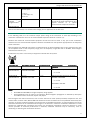
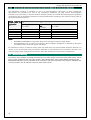
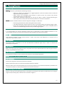
INTEGRUS PSV ANAESTHESIA VENTILATOR
SERVICE MANUAL
Integrus PSV Ventilator Service Manual
This page intentionally left blank
2
Integrus PSV Ventilator Service Manual
Copyright © 2005 by Ulco Medical
All rights reserved.
No part of this publication may be reproduced in any form, in an electronic retrieval system or otherwise, without
the written permission of Ulco Medical.
All Ulco products are subject to a program of continuous development and the manufacturer reserves the right to
make alterations in design and equipment without prior notice.
Document Number: EV9-UM-004
Version: 1.0
3
Integrus PSV Ventilator Service Manual
Table of Contents
1
2
Introduction ................................................................
................................................................................................
...................................................................
................................... 6
1.1
About this manual ................................................................................................................................. 6
1.2
Qualifications for Servicing ................................................................................................................... 6
1.3
Units ....................................................................................................................................................... 6
Ventilator Overview ................................................................
.......................................................................................
....................................................... 7
2.1
3
Major features ....................................................................................................................................... 7
Description ................................................................
................................................................................................
....................................................................
.................................... 8
3.1
Device Classification ............................................................................................................................. 8
3.2
Electromagnetic Compatibility.............................................................................................................. 8
3.2.1
Electromagnetic Emissions ................................................................................................... 8
3.2.2
Electromagnetic Immunity .................................................................................................... 8
3.2.3
Recommended Separation Distance.................................................................................... 9
3.2.4
Recommended Separation Distances from Portable and Mobile RF Communication
Equipment ........................................................................................................................................... 10
3.3
4
Servicing Overview ................................................................
......................................................................................
......................................................11
......................11
4.1
Warnings and Cautions....................................................................................................................... 11
4.2
Responsibilities of Service Personnel ................................................................................................ 11
4.3
Risks..................................................................................................................................................... 11
4.4
5
4
Workstation Mounting......................................................................................................................... 10
4.3.1
Explosion .............................................................................................................................. 11
4.3.2
Electrical............................................................................................................................... 11
4.3.3
Contamination ..................................................................................................................... 11
Preparation and Completion of Service ............................................................................................. 11
4.4.1
Preparation .......................................................................................................................... 11
4.4.2
Removing the rear access panels ...................................................................................... 11
4.4.3
After Service......................................................................................................................... 13
4.5
Seals .................................................................................................................................................... 13
4.6
Service Intervals and Kits ................................................................................................................... 13
4.6.1
Ventilator Routine Preventative Maintenance Intervals.................................................... 14
4.6.2
6 Month Performance Check .............................................................................................. 14
4.6.3
12 Month Service ................................................................................................................ 14
4.6.4
36 Month Battery Service ................................................................................................... 14
4.7
Tools..................................................................................................................................................... 14
4.8
Environmental protection ................................................................................................................... 15
Calibration Procedure ................................................................
.................................................................................
.................................................16
.................16
Integrus PSV Ventilator Service Manual
5.1
Introduction ......................................................................................................................................... 16
5.1.1
6
5.2
Method................................................................................................................................................. 16
5.3
Procedures........................................................................................................................................... 16
5.3.1
Drive Gas Pressure Sensor Calibration .............................................................................. 17
5.3.2
Drive Flow Sensor Calibration ............................................................................................. 17
5.3.3
Flow Valve Profile Calibration.............................................................................................. 19
5.3.4
Pressure Sensor Calibration ............................................................................................... 20
5.3.5
Commit New Calibration File............................................................................................... 22
Service Procedures ................................................................
.....................................................................................
.....................................................23
.....................23
6.1
Access to Ventilator housing .............................................................................................................. 23
6.2
Removal of Ventilator housing from the anaesthesia machine. ...................................................... 25
6.3
12 Monthly Service ............................................................................................................................. 26
6.4
7
Tools to be used .................................................................................................................. 16
6.3.1
EV9000-99 Service kit ........................................................................................................ 26
6.3.2
Tools to be used .................................................................................................................. 26
6.3.3
Preparation to service Ventilator ........................................................................................ 26
6.3.4
Service Procedure................................................................................................................ 26
6.3.5
Testing.................................................................................................................................. 28
36 Monthly Service ............................................................................................................................. 29
6.4.1
EV9000-98 Battery Service kit ........................................................................................... 29
6.4.2
Tools to be used .................................................................................................................. 29
6.4.3
Preparation to service Ventilator ........................................................................................ 29
6.4.4
Service Procedure................................................................................................................ 29
6.4.5
Testing.................................................................................................................................. 30
System Diagrams ................................................................
........................................................................................
........................................................31
........................31
7.1
System Component Diagram.............................................................................................................. 31
7.2
Ventilator Pneumatic Block Diagram ................................................................................................. 32
7.3
Ventilator Electronics Block Diagram................................................................................................. 32
7.4
Ventilator Wiring Diagram ................................................................................................................... 33
5
Integrus PSV Ventilator Service Manual
1 Introduction
1.1
About this manual
This manual provides information for the maintenance and service of the Integrus PSV anaesthesia ventilator.
Although this equipment has been carefully designed for simplicity of assembly and use, it is recommended that
the contents of this manual be studied before attempting maintenance of the equipment. Explanatory diagrams
are provided in order to help the reader understand the concepts described.
This service manual should be read in conjunction with the user manual.
1.2
Qualifications for Servicing
All personnel who service or repair Ulco products must have a current valid Ulco Training Certificate for the
product being serviced or repaired.
1.3
Units
Current........................................................................................ Amperes (A)
Flow ............................................................................................ Litres per Minute (L/min or LPM)
Frequency................................................................................... Kilohertz (kHz)
.................................................................................................... Gigahertz (GHz)
.................................................................................................... Megahertz (MHz)
Lengths....................................................................................... Millimetres (mm)
Pressure (airway) ...................................................................... centimetres of water (cmH2O)
Pressure (High) .......................................................................... Kilopascals (kPa)
Voltage................................................................................ ....... Volts (V)
Weight......................................................................................... Kilograms (kg)
6
Integrus PSV Ventilator Service Manual
2 Ventilator Overview
The Integrus PSV ventilator is intended for use on humans, from neonate to adult. It must be used as part of an
integrated anaesthesia workstation, such as the Ulco Integrus. The ventilator is micro-processor controlled and
usually operates in a time-cycled, gas driven mode. The unit has various ventilation modes such as Volume
Controlled Ventilation (VCV) with or without Pressure Limiting, Pressure Controlled Ventilation (PCV), Positive End
Expiratory Pressure (PEEP) and Continuous Positive Airway Pressure (CPAP). It also includes several patientinitiated ventilation modes such as Synchronised Intermittent Mandatory Ventilation (SIMV) and Pressure Support
Ventilation (PSV).
The Integrus PSV can also operate in a closed-loop fashion in the volume controlled modes, by using a unique
distal flow sensor. The flow sensor allows the ventilator to compensate for breathing circuit compliance, leakage
and fresh gas flows by measuring precisely the flows into and out of the patient airway. This mode may also be
disabled for more classical approach to volume delivery.
The display of Integrus PSV is an 8.4” LCD TFT flat panel which gives a very bright display under a variety of
lighting conditions and allows the operator to select from a number of different display graphs such as
simultaneous display of flow, pressure and volume or the display of respiratory loop graphs.
If equipment that has not been specifically designed or supplied by Ulco is to be attached to the ventilator, it is
recommended that customers consult Ulco as to the suitability of the equipment and necessary modifications to
the apparatus.
Ulco and its agents provide a comprehensive regular maintenance service and it is recommended that advantage
be taken for the safe and reliable upkeep of this equipment. Refer to this service manual for details on how to
maintain your Ulco machine. There is a service contract included with the equipment – please fill it in and return
it to Ulco.
Customers requiring further service or advice with operating problems should contact Ulco or one of their
accredited agents.
2.1
Major features
Closed loop control of volume delivery
Distal flow sensor ensures accurate exhaled volume measurements
Advanced ventilation modes such as SIMV and Pressure Support
Loops display
Integration with Integrus workstation and CBS bellows/absorber system
7
Integrus PSV Ventilator Service Manual
3 Description
3.1
Device Classification
The Integrus PSV Anaesthetic Ventilator is classified as follows:
• Class I equipment for the purposes of electrical safety
• Type CF applied part
• Continuous Operation
3.2
Electromagnetic Compatibility
3.2.1
Electromagnetic Emissions
The Integrus-PSV anaesthetic ventilator is suitable for use in the electromagnetic environment specified in the
table below. The user must ensure that it is used in such an environment.
Emissions
Emissions test
Radio Frequency
(RF) emissions
Compliance
Group 1
RF
emissions
CISPR 11
Harmonic
emissions
IEC
61000-3-2
Voltage
fluctuations IEC
61000-3-3
Class A
3.2.2
Not applicable
Avoiding Electromagnetic Interference
The anaesthetic ventilator uses RF energy only for its
internal function. Therefore, its RF emissions are very low
and are not likely to cause any interference in nearby
electronic equipment.
The anaesthetic ventilator is suitable for use in all
establishments other than domestic and those directly
connected to the public low-voltage power supply network
that supplies buildings used for domestic purposes.
Not applicable
Electromagnetic Immunity
The Integrus-PSV anaesthetic ventilator is suitable for use in the specified electromagnetic environment. The user
must ensure that it is used in the appropriate environment as listed below.
Immunity test
IEC60601 test level
Electrostatic
discharge (ESD)
± 6 kV contact
± 8 kV air
IEC61000-4-2
Electrical
fast
transient/burst
± 2 kV for power supply
lines
IEC 61000-4-4
± 1 kV for input/output
lines
Surge
± 1 kV differential mode
IEC 61000-4-5
± 1 kV common mode
Voltage
dips,
short
interruptions and
voltage
variations
on
power
supply
input lines
< 5% UT
(> 95% dip in UT)
for 0.5 cycle
IEC 61000-4-11
70% UT
8
40% UT
(60% dip in UT)
for 5 cycles
Compliance level
Electromagnetic
environment
–
guidance
Floors should be wood, concrete or
ceramic tile. If floors are covered with
synthetic material, the relative
humidity should be at least 30%.
Mains power quality should be that of
a typical commercial or hospital
environment.
Mains power quality should be that of
a typical commercial or hospital
environment.
Mains power quality should be that of
a typical commercial or hospital
environment. If the user of the
anaesthetic
ventilator
requires
continued operation during power
mains
interruptions,
it
is
recommended that the anaesthetic
workstation be powered from an
uninterruptible power supply or a
Integrus PSV Ventilator Service Manual
(30% dip in UT)
for 25 cycles
battery.
< 5% UT
(> 95% dip in UT)
for 5 sec
Power frequency
(50/60
Hz)
magnetic field
3 A/m
Power frequency magnetic fields
should be at levels characteristic of a
typical location in a
typical
commercial or hospital environment.
IEC 61000-4-8
Note: In the table above, UT is the AC mains voltage prior to application of the test level.
3.2.3
Recommended Separation Distance
In the following table, P is the maximum output power rating of the transmitter in watts (W) according to the
transmitter manufacturer and d is the recommended separation distance in metres (m).
Portable and mobile RF communication equipment should be used no closer to any part of the anaesthetic
ventilator than the recommended separation distance calculated from the equation appropriate for the frequency
of the transmitter.
Field strengths from fixed RF transmitters, as determined by an electromagnetic site survey, should be less than
the compliance level in each frequency range (over the frequency range 150 kHz to 80 MHz, field strengths
should be less than 3 V/m).
Interference may occur in the vicinity of equipment marked with this symbol:
Immunity test
IEC 60601 test level
Compliance level
Conducted RF
IEC 61000-4-6
3 Vrms
150 kHz to 80 MHz
3 Vrms
Electromagnetic
environment
guidance
Recommended separation distance:
d = 1.2√P
Radiated RF
IEC 61000-4-3
3 V/m
80 MHz to 2.5 GHz
3 V/m
Recommended separation distance:
80 MHz to 800 MHz
d = 1.2√P
800 MHz to 2.5 GHz
d = 2.3√P
Notes:
• At 80 MHz and 800 MHz, the higher frequency range applies.
• These guidelines may not apply in all situations. Electromagnetic propagation is affected by absorption
and reflection from structures, objects and people.
Field strengths from fixed transmitters, such as base stations for radio (cellular/cordless) telephones and ;and
mobile radios, amateur radio, AM and FM radio broadcast and TV broadcast cannot be predicted theoretically with
accuracy. To assess the electromagnetic environment due to fixed RF transmitters, an electromagnetic site survey
should be considered. If the measured field strength in the location in which the anaesthetic workstation is used
exceeds the applicable RF compliance level above, the anaesthetic workstation should be observed to verify
normal operation. If abnormal performance is observed, additional measures may be necessary, such as
reorienting or relocating the anaesthetic ventilator.
9
Integrus PSV Ventilator Service Manual
3.2.4
Recommended Separation Distances from Portable and Mobile RF Communication Equipment
The anaesthetic ventilator is intended for use in an electromagnetic environment in which radiated RF
disturbances are controlled. The user of the anaesthetic workstation can help prevent electromagnetic
interference by maintaining a minimum distance between portable and mobile RF communications equipment
(transmitters) and the anaesthetic ventilator as recommended below, according to the maximum output power of
the communications equipment.
Rated maximum
output power of
transmitter
W
0.01
0.1
1
10
100
Separation distance according to frequency of transmitter
m
150 kHz to 80 MHz
80 MHz to 800 800 MHz to 2.5 GHz
d = 1.2√P
MHz
d = 2.3√P
d = 1.2√P
0.1
0.1
0.2
0.4
0.4
0.7
1.3
1.3
2.3
3.8
3.8
7.3
12.0
12.0
23.0
Notes:
• At 80 MHz and 800 MHz, the separation distance for the higher frequency range applies.
• These guidelines may not apply in all situations. Electromagnetic propagation is affected by absorption
and reflection from structures, objects and people.
For transmitters rated at a maximum output power not listed above, the recommended separation distance d in
metres (m) can be estimated using the equation applicable to the frequency of the transmitter, where P is the
maximum output power rating of the transmitter in watts (W) according to the transmitter manufacturer.
3.3
Workstation Mounting
The Integrus PSV ventilator is normally mounted in the rear of the Integrus anaesthesia workstation, with a control
panel (screen) mounted on the side of the machine. The ventilator drives a descending bellows mounted on the
CBS (bellows/absorber system). Operation of the ventilator is further described in the user manual; calibration and
service procedures are described in sections 5 and 6 of this manual.
10
Integrus PSV Ventilator Service Manual
4 Servicing Overview
4.1
Warnings and Cautions
Warning indicates a potentially life threatening situation:
o Never oil or grease any anaesthesia or oxygen equipment unless the lubricant used is made and
approved for this type of service.
o Never connect the scavenging valves directly to vacuum source. The vacuum may remove
required gases from the patient circuit.
o Never cover anaesthesia equipment with any type of fabric or plastic covering. Removing the
cover may cause a build up of static electricity, which can cause fire or explosion.
Caution indicates condition which can lead to equipment damage or malfunction
o Avoid using excessive force when closing flow controls valves.
o Turn OFF anaesthesia machine when not used, to minimise possibility of depleting oxygen supply
o Ensure that all gas flow control valves are turned fully clockwise before system ON/OFF switch is
turned on to avoid damage to flow tubes by sudden surge of gases.
4.2
Responsibilities of Service Personnel
It is recommended that service procedures should only be performed by ULCO certified technicians at the
recommended intervals. A service record should be kept by Hospital and the service provider.
4.3
Risks
Only personnel certified by ULCO should attempt to repair and service ULCO Equipment to minimize risk of
malfunction and/or patient injury.
4.3.1 Explosion
The Integrus PSV is restricted to use with non-flammable anaesthetic agent only in order to minimise the
possibility of an explosion.
4.3.2 Electrical
Before removing any of the machines covers, the power cord must be detached from the mains supply in order to
prevent the possibility of electric shock.
4.3.3 Contamination
A bacterial filter should be used to prevent contamination of anaesthesia equipment.
4.4
Preparation and Completion of Service
4.4.1 Preparation
Anaesthesia equipment should be cleaned and sterilized.
Genuine ULCO spare parts for all critical assemblies should be available.
Read the section of this manual appropriate to the service procedure to be performed. Calibration procedures are
to be found in Section 5, and service procedures are outlined in Section 6
4.4.2 Removing the rear access panels
Access to the bulk of the gas supply system is achieved by removing the rear plastic moulded cover by turning the
single hex key retaining clip to free the cover as shown in Figure 1.
11
Integrus PSV Ventilator Service Manual
Rotate counter
clockwise using hex
key to release cover
Figure 1: Rear top cover of Integrus workstation
Access to the some of the gas supply system and the ventilator is achieved by removing the rear metal cover plate
in the lower half of the machine. This can be done by removing the four screws affixing the cover plate in place
using a 4mm Allen key, as shown in Figure 2.
12
Integrus PSV Ventilator Service Manual
Remove four screws
Figure 2: Rear metal cover
4.4.3 After Service
Anaesthesia Equipment should be tested according to Ulco’s recommended procedures and a service sticker
signed off by a certified technician before releasing the machine into operation.
Test and calibration procedures for all serviceable items are to be found in Sections 5 and 6 of this manual.
4.5
Seals
All seals on high pressure components such as the first stage regulators must be lightly greased with Krytox or
similar grease certified safe for use in high pressure oxygen environments. Low pressure components in the
patient airway may use standard silicone greases.
4.6
Service Intervals and Kits
Ulco recommends twelve monthly service periods at a minimum. This should include the change over of all service
kits for critical assemblies as defined in the table included below.
13
Integrus PSV Ventilator Service Manual
In addition to regular servicing of the equipment ULCO also recommends that performance testing is carried out
as often as necessary, but at minimum every six months.
Item No.
1.
2.
Product.
Integrus PSV Service Kit
Integrus PSV Battery Kit
Interval in Months.
12
36
Qty
1
1
Part. No.
EV9000-99
EV9000-98
4.6.1 Ventilator Routine Preventative Maintenance Intervals
Routine maintenance consists of a periodic routines plus extended service:
•
•
•
4.6.2
6 MONTH PERFORMANCE CHECK
12 MONTH SERVICE
36 MONTH BATTERY SERVICE
6 Month Performance Check
Comprising:
• Electrical Inspection to ensure the integrity of the mains power lead, mains plug and all socket outlets,
including fuses.
• Replace Bodok cylinder seals
CARRY OUT FULL FUNCTIONAL CHECK (and make any adjustments that are necessary), as follows:
• Check Gas supply hoses
• Check operation of electrical system and test earth continuity and electrical safety according to local
protocols
• Test and check calibration of the ventilator with a ventilator tester
4.6.3
12 Month Service
Comprising:
• Replace consumable items
• Carry out service, calibration and functional tests.
CARRY OUT THE FOLLOWING TESTS:
• Electrical Safety Test
• Full Functional Test and Calibration of Ventilator
See Section 6.3 for full description of the 12 month service.
4.6.4
•
•
36 Month Battery Service
As 12 month service
Battery replacement
See Section 6.4 for full description of the 36 month service.
4.7
Tools
The following table details special tools which may be ordered from Ulco:
Circuit pressure manometer adapter
Timeter Respical or similar device for measuring
flows and pressures of both air and oxygen
Part Number
CN22MFQ-M5
RT200, T300
In addition, the following commonly available tools are required to complete most of the service procedures
in this manual:
Phillips head screwdriver
Long nose pliers
Metric Allen key set
14
Integrus PSV Ventilator Service Manual
4.8
Environmental protection
The ventilator is provided with a maintenance-free sealed lead-acid battery, which, when fully charged,
ensures
interruption-free operation for over 30 minutes in the event of mains failure. Ensure that the battery is not
disposed of in domestic refuse; but is disposed of as hazardous waste at the waste disposal facilities provided by
the local authorities. The battery can be removed at the end of the machine’s life, in order to be disposed of
according to the method prescribed. The battery’s materials can be recycled.
The ventilator is made mainly of metals, which should be recycled at the end of the machine’s life. Electronic
scrap should be disposed of in accordance with local regulations, or by returning the ventilator to Ulco for proper
disposal.
The machine contains electric components which generate electric and magnetic radiation. Radiation intensity is
tested in accordance with EN 55011 for electromagnetic compatibility. Noise emission is below 55 dB (A).
15
Integrus PSV Ventilator Service Manual
5 Calibration Procedure
5.1
Introduction
The factory calibration functions and patient flow sensor calibration are accessed from the ‘admin’ menu. The
admin menu is accessed by pressing the third and fifth soft touch keys on the ventilator display simultaneously.
When these keys are pressed, the system will ask the user for a password in order to access the admin menu
functions.
Factory calibration should only be performed by trained personnel using an accurate flow/pressure measurement
device. Note that the admin password is factory set to “ab”. It may be changed to a new setting from the service
menu itself.
5.1.1 Tools to be used
5.2
Pressure and flow measuring calibration device such as Timeter RT200 or Respical T300
CN22MFQ-M5 22mm circuit adapter with quick connect fitting and M5 nipple
Method
The factory calibration has four phases of operation:
1. Drive Gas Input Pressure Sensor Calibration.
2. Drive Flow Sensor Calibration.
3. Flow Valve Profile Calibration.
4. Drive and Patient Pressure Sensor Calibration.
Each of these phases will be presented to the user in the order above with brief instructions via a dialogue box. At
the conclusion of the calibration a dialogue box is presented to the user asking if the new calibration information
should be ‘committed’ to the ventilator as the new calibration settings.
Each individual calibration may also be ‘skipped’ via the dialogue box to the next calibration if, for example, the
calibration step currently indicated has been previously performed. For example, if during calibration phase ‘4’ it
has been discovered that the drive pressure sensor was faulty, this will be indicated by the ventilator informing the
user that the calibration offset or scale are out of range. The calibration phases ‘1’-‘3’ will have been performed
already so it is not necessary to do them again. After the faulty drive pressure sensor has been repaired the
calibration may be repeated but ‘skipping’ the first three phases only having to repeat phase ‘4’. Using the method
described above, if a problem is discovered, the calibration phases may be selectively performed as necessary.
Refer to Section 7.2 for the location of the sensors within the pneumatic circuit of the ventilator.
In Phase 1, the sensor at the supply gas side of the circuit, before the 255 kPa regulator, is calibrated. This sensor
is calibrated with two points, a zero point and the 415 kPa normal operating point.
In Phase 2, the DGF sensor is calibrated. This sensor is calibrated with two points, a zero point and at 50 LPM.
In Phase 3, the DGV control voltages are calibrated. This procedure is performed at ten points across the entire
flow range of the valve.
In Phase 4, both the DGP and PGP sensors are calibrated simultaneously. These sensors are calibrated with two
points, a zero point and at 40 cmH2O.
The procedure for calibrating the Patient Flow Sensor (PGF) is handled separately. Because the patient Flow
Sensor is a disposable item it must be able to be calibrated by the ‘end user’, usually a Biomedical Engineer, when
the sensor is replaced. The procedure for this calibration procedure is discussed in the User Manual.
5.3
Procedures
The ‘Factory Calibration’ item is found in the ‘Admin’ menu. The admin menu is accessed by pressing the third and
fifth soft touch keys on the ventilator display simultaneously. When these keys are pressed, the system will ask
16
Integrus PSV Ventilator Service Manual
the user for a password in order to access the admin menu functions. Note that the admin password is factory set
to “ab”.
5.3.1 Drive Gas Pressure Sensor Calibration
Calibration
Upon selecting ‘Factory calibration’ from the admin menu the user will be presented with the following screen:
Figure 3: Mains pressure sensor calibration
As the dialogue box indicates, the first calibration is for the ‘Drive gas Pressure Sensor’. The ‘Skip’ and ‘Continue’
buttons are selected using the ventilator knob and activated by pressing the knob in. Selecting ‘Skip’ abandons
the ‘Drive Gas Pressure Sensor Calibration’ and advances to ‘Drive Flow Sensor Calibration’.
Before this calibration is done the oxygen supply gas hose must be removed from the machine and any residual
pressure purged from the system using the O2 flush button. The calibration routine uses this as a zero reference
point before continuing.
When the ‘Continue’ button is selected and pressed a new dialogue appears instructing the user to reconnect the
drive gas hose. The oxygen supply pressure must be in the range 390-410 kPa as indicated on the workstation
pressure gauge.
Press ‘Continue’. If the calibration is successful the user will now be presented with the dialogue box for ‘Drive
Flow Sensor Calibration’.
5.3.2 Drive Flow Sensor Calibration
The user is presented with the following screen:
17
Integrus PSV Ventilator Service Manual
Figure 4: Drive Flow Sensor
Sensor Calibration
Selecting ‘Skip’ will advance to the ‘Flow Valve Profile Calibration.
To continue with the Drive Flow Sensor Calibration, the bellows drive hose from the workstation to the CBS
absorber must be removed from the absorber and connected to the flow input of a suitable flow calibration device
such as a RespiCal T300 or Timeter RT200 (See Figure 5).
At this point the flow calibrator must indicate zero flow before continuing. Select and press ‘Continue’.
0.0
Bellows
Drive
Connector
LPM
Flow Calibration
Device
Figure 5: Connection of ventilator to flow calibration device
When the ‘Continue’ button is selected and the knob pressed the user is presented with another dialog box
instructing the user to set a flow of 50 LPM. Two buttons are presented: ‘Abort’ and ‘Continue’.
After pressing ‘Continue’ the front panel knob is used to adjust the air flow. Turning anticlockwise reduces the
flow; turning clockwise increases the flow.
When the flow indicated on the calibration flow meter is 50 LPM +/- 2 LPM, press the knob in to register the
setting. If the calibration is successful the user will now be presented with the dialogue box for ‘Flow Valve Profile
Calibration’.
18
Integrus PSV Ventilator Service Manual
5.3.3 Flow Valve Profile Calibration
The user is presented with the following screen:
Figure 6: Flow Valve Profiling
Selecting ‘Skip’ will advance to the Pressure Sensor Calibration. To continue with the Flow Valve Profile
Calibration, the hose setup can be left the same as for the Drive Flow Sensor Calibration done previously. At this
point the flow calibration device must indicate zero flow before continuing. Select and press ‘Continue’
When the ‘Continue’ button is selected with the knob and the knob pressed the user is presented with another
dialog box instructing the user to set a flow of 10 LPM. Two buttons are presented: ‘Skip’ and ‘Continue’. After
pressing ‘Continue’ the front panel knob is used to adjust the air flow. Turning anticlockwise reduces the flow;
turning clockwise increases the flow. When the flow indicated on the flow meter is 10 LPM press the knob in to
register the setting.
If the calibration is successful the user will now be presented with the dialogue box for 20 LPM. The same
procedure is followed to set the new flow point. The calibration routine will repeat this step up to 100 LPM in 10
LPM increments. Each flow should be set to with 10% of the target flow, so that the reading from the flow
calibrator is within 10% of the target flow, up to a maximum of 2 LPM. For example, at 10 LPM the flow measuring
device should be in the range 9 – 11 LPM for a correct calibration point. At 60 LPM, the flow measuring device
should be in the range 58 – 62 LPM for a correct calibration point.
If the valve is not capable of generating the desired flow the ‘Skip’ option should be selected. Note that if the flow
valve cannot generate a flow in excess of 80 LPM the valve is incorrectly adjusted. This must be attended to and
the calibration repeated.
If the calibration is successful the user will now be presented with the dialogue box for ‘Pressure Sensor
Calibration’.
19
Integrus PSV Ventilator Service Manual
5.3.4 Pressure Sensor Calibration
The user is presented with the following screen:
Figure 7: Pressure Sensor Calibration
Selecting ‘Skip’ will complete the calibration. To continue with the Pressure Sensor Calibration follow these steps:
The hose from the workstation (bellows drive output) must be removed from the CBS and connected to an adapter
(part number CN22MFQ-M5). The adapter has a quick connect fitting which should be connected to the ventilator
patient pressure connector. The adapter also has an M5 nipple suitable for connection to 6mm tubing which can
be connected to the pressure input of the calibration analyser. The 22mm end of the adapter should be
stoppered. Refer to Figure 8.
The calibration analyser should be set in pressure mode and read a zero pressure before continuing. When ready
select and press ‘Continue’.
20
Integrus PSV Ventilator Service Manual
Patient
Pressure
Connector
CPC Quick Fit
Connector
Rubber 22mm
Plug
Bellows
Drive
Connector
CN22MFQ−M
5
5mm Nipple
Pressure Calibration
Device
0.0
cmH2O
Figure 8: Connection of ventilator for pressure calibration step
When the ‘Continue’ button is selected with the knob and the knob pressed the user is presented with another
dialog box instructing the user to set a pressure of 40 cmH2O. Two buttons are presented: ‘Abort’ and ‘Continue’.
After pressing ‘Continue’ the front panel knob is used to adjust the air pressure. Turning anticlockwise reduces the
pressure; turning clockwise increases the pressure. When the pressure indicated on the calibration analyser
pressure gauge is 40 cmH2O +/- 2 cmH2O, press the knob in to register the setting. If the calibration is successful
the user will now be presented with the dialogue box to ‘Commit New Calibration File’.
21
Integrus PSV Ventilator Service Manual
5.3.5 Commit New Calibration File
This is the final stage of the Factory Calibration procedure where the calibration results are ‘written away’
permanently into the ventilator file system. Select and press the ‘Yes’ button to do this otherwise the calibration
results will be discarded.
Figure
Figure 9: Committing calibration results to file
22
Integrus PSV Ventilator Service Manual
6 Service Procedures
6.1
Access to Ventilator housing
Tools: 4 mm Allen key, 2.5mm Allen key, flat blade screwdriver
Caution
Observe anti-static precautions when working on the electronic components of the ventilator.
1. Apply the brakes to the front wheels of the machine
2. Disconnect all gas supplies and ensure that the system is purged.
3. Ensure that the Integrus PSV workstation is disconnected from the electrical supply before commencing
any maintenance procedure that requires the dismantling of the covers etc. For certain procedures the
power can be restored with care after the covers have been removed.
4. Remove both rear covers as described in Section 4.4.2
5. The ventilator is mounted in a removable case with handle as shown in Figure 10. Grasp the ventilator
handle in one hand and steady the lower half of the ventilator housing case with the other hand.
6. Pull up firmly so that the mounting slides up the slots in the frame
7. Pull the ventilator housing towards you so that the mounting tabs come out of the frame slots
8. Rest the ventilator housing on the plastic skirt at the rear of the workstation as shown in Figure 11
23
Integrus PSV Ventilator Service Manual
Removal
handle
Ventilator
housing
Mounting slots
Ventilator
module
Figure 10:
10: Ventilator housing
24
Integrus PSV Ventilator Service Manual
Mounting tabs
Mounting slots
Plastic
Skirt
Figure 11:
11: Ventilator housing in service access position
6.2
Removal of Ventilator housing
housing from the anaesthesia machine.
Tools: 4 mm Allen key, 2.5mm Allen key, flat blade screwdriver
1.
2.
3.
4.
5.
6.
7.
8.
9.
Disconnect all gas supplies and ensure that the system is purged.
Disconnect Electrical supply.
Remove both rear covers as described in section 4.4.2
Remove the all of the connections shown on the top plate of the ventilator in Figure 12.
The ventilator is mounted in a removable case with handle as shown in Figure 10. Grasp the ventilator
handle in one hand and steady the lower half of the ventilator housing case with the other hand.
Pull up firmly so that the mounting slides up the slots in the frame
Pull the ventilator housing towards you so that the mounting tabs come out of the frame slots and remove
the entire assembly.
To refit repeat the operations in reverse order, take care when sliding housing into position that the
connections and tubing do not become snagged or kinked.
When the housing has been fitted, carry out full functional check before fitting rear covers.
25
Integrus PSV Ventilator Service Manual
Figure 12:
12: Ventilator Connections
6.3
12 Monthly Service
6.3.1 EV9000EV9000-99 Service kit
-
3 off OR-5116S
1 off R07-99
O-ring
RO7 kit
6.3.2 Tools to be used
-
1.5mm, 2.5 mm and 4 mm Allen keys
Philips screwdriver
Flat screwdriver
1” spanner
Silicone grease Molykote 111.
Adjustable wrench.
Grease Dupont Krytox GPL-205
Tweezers
6.3.3 Preparation to service Ventilator
1. Make sure that the anaesthetic machine is OFF.
2. Gain access to the ventilator housing: See Section 6.1.
6.3.4 Service Procedure
1. Replacement of oo-rings OROR-5116S
5116S. Refer to Figure 13.
13.
a. Pull out the exhaust gas tube (EV910424) and replace the O-ring in the groove on the tube and smear
with silicone grease.
b. Pull out the drive gas tube (EV9104251) and replace the O-ring in the groove on the tube and smear
with silicone grease.
c. Pull out the blow off gas tube (EV910426).
d. Unscrew the 12 retaining screws on the top plate. Carefully lever the top plate back taking care to
ensure that none of the cables connecting it to the body of the ventilator become disconnected.
e. Using tweezers, remove the O-ring from inside the blow off gas tube receptacle on the flow block. Smear
the O-ring groove with silicone grease and insert the new O-ring.
26
Integrus PSV Ventilator Service Manual
Figure 13:
13: OO-ring replacement
2. Replacement of components to be serviced on R07 regulator. Refer to Figure 14
a.
b.
c.
d.
Unscrew the nut of the R07 regulator by using the adjustable wrench.
Replace diaphragm assembly and nylon washer.
Unscrew poppet valve holder with a Philips screwdriver.
Reassemble everything and put it back into the anaesthesia workstation.
27
Integrus PSV Ventilator Service Manual
Figure 14:
14: Exploded
Exploded view of R07 Regulator
6.3.5 Testing
Testing
a.
28
Adjust RO7 regulator to set pressure of 255 kPa
Integrus PSV Ventilator Service Manual
6.4
36 Monthly Service
6.4.1 EV9000
EV9000000-98 Battery Service kit
-
1 off EV9000-99
1 off EV9108
Service Kit
7.2 Ah SLA Battery
6.4.2 Tools to be used
-
1.5mm, 2.5 mm and 4 mm Allen keys
Philips screwdriver
Flat screwdriver
1” spanner
Silicone grease Molykote 111.
Adjustable wrench.
Grease Dupont Krytox GPL-205
Tweezers
6.4.3 Preparation to service Ventilator
1. Make sure that the anaesthetic machine is OFF.
2. Disconnect the machine from the mains AC supply.
3. Gain access to the ventilator housing: See Section 6.1.
6.4.4 Service Procedure
1. Perform 12 month service. See Section 6.3.
6.3.
a. Replace O-rings, inlet regulator kit and recalibrate inlet regulator.
2. Replace battery. Refer to Figure 15.
15.
a. Remove the main cover plate from the ventilator enclosure by removing all screws.
b. Disconnect the two battery terminal connections.
c. Remove the four pan head screws holding down the battery plate and battery and remove the battery plate
and battery.
d. Install the new battery in the same location and screw down the battery plate onto the battery plate spacers
so that the battery is firmly held in place.
e. Reconnect the two battery terminal connections.
29
Integrus PSV Ventilator Service Manual
Figure 15:
15: Removal of battery
6.4.5 Testing
Testing
1. Test of Battery
Start ventilator with standard default settings, disconnect power supply while ventilating, and verify that the
ventilator continues ventilating and a high priority alarm is generated. Reconnect mains and set ventilator to
Standby. When fully charged the battery will last 30 minutes.
30
Integrus PSV Ventilator Service Manual
7 System Diagrams
7.1
System Component Diagram
Ventilator
(EV-91)
VGA,
control
signals
Display
Module
(EV-92)
Supply
Pressure
Bellows drive,
Patient flow and
pressure,
bag/vent switch
position
Fresh
gas
Gas
Delivery
System
CBS
(AB800C)
31
Integrus PSV Ventilator Service Manual
7.2
Ventilator Pneumatic Block Diagram
Electronics DGV
Control Signal
Driving
Gas Inlet
Connector
Drive Gas Flow
Sensor (DGF)
Drive Gas Pressure
Sensor (DGP)
To Drive Gas
Pressure Sensor
Inlet Regulator
RO7−1
Drive Gas Valve
(DGV) EV9122
Electronics EGV
Control Signal
To electronics
DGF sensor
Bellows
Drive
Connector
To electronics
DGP sensor
Pressure Relief
Valve (68 cmH2O)
Pressure
Relief
Connector
Ventilator
Exhaust
Connector
Exhaust Gas Valve
(EGV) EV9121
7.3
32
Ventilator Electronics Block Diagram
Patient
Flow
Connector
Patient
Pressure
Connector
To electronics
PGF sensor
To electronics
PGP sensor
Integrus PSV Ventilator Service Manual
7.4
Ventilator Wiring Diagram
33