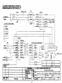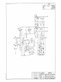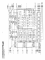
1
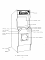
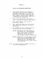
ccniun
SERVICE
,INC.
MANUAL
364-62-0100 A
TABLE OF CONTENTS
PAGE NO.
I.
INTRODUCTION
USER INFORMATION
II.
III.
IV.
-
F.C.C.
1
GAME DESCRIPTION (DIAGRAM)
2
GAME SUMMARY
3,
SPECIFICATIONS
:
INSTALLATION
4
ELECTRICAL REQUIREMENTS
110/2 2 CONVERSION INSTRUCTIONS
4
OPERATION
5
:
GAME INSTRUCTIONS
6
GAME SCORING
6
ROUTINE MAINTENANCE AND SERVICE
7
OPERATOR OPTIONAL SWITCH SETTINGS
8
OPTIONAL SWITCH SETTINGS
8
GENERAL
:
C.P.U. PARTS LIST
v.
4
9,
LOGIC BOARD PARTS LIST
11
SHINDENGEN POWER SUPPLY PARTS LIST
12,
DRAWINGS
:
110/220 POWER INTERCONNECT DIAGRAM (361-10-0900)
14
C.P.U. HARNESS INTERCONNECT DIAGRAM 364-10-1000)
(
15
SHINDENGEN POWER SUPPLY SCHEMATIC
(363-17-0300)
16
C.P.U. BOARD SCHEMATIC
(364-62-0900)
17
LOGIC BOARD SCHEMATIC
(364-62-0800)
18
COIN DOOR WIRING DIAGRAM
(364-62-1000)
19
10
13
#364-62-0600
USER INFORMATION
-
F.C.C,
WARNING:
This equipment generates, uses and can radiate
radio frequency energy and if not installed and
used in accordance with the instructions manual,
may cause interference to radio communications.
As temporarily permitted by regulation, it has
not been tested for compliance pursuant to Subpart
J of Part 15 of F.C.C. Rules, which are designed
to provide reasonable protection against such interference.
Operation of this equipment in a residential
area is likely to cause interference in which case the
user at his own expense will be required to take
whatever measures may be required to correct the
interference
-1-
MARQUEE
VIEWING GLASS
BEZEL
1- PLAYER BUTTON
^r
CONTROL PANEL
LEFT MOTION
BUTTON
2-PLAYER BUTTON
FIRE BUTTON
FORCE FIELD BUTTON
RIGHT MOTION
BUTTON
COIN DOOR ASSEMBLY
LINE CORD
19" PHOENIX VIDEO UPRIGHT
-2-
PHOENIX
PHOENIX is an exciting new space game, with special
audio and visual effects, challenging the skills of the
most experienced player. Fascinating visual graphics
and extraterrestrial sounds add to the intensity of
this game.
There are five basic stages to each round of play.
After a melodious introduction, the first stage begins
with a wave of sixteen (16) small Phoenixes attacking
the spaceship.
They drop missiles and dive at the
spaceship, in an effort to destroy it.
The spaceship maneuvers left and right, evading
the missiles and birds, and fires rockets, attempting
to destroy the birds.
The spaceship can utilize the "Force Field" as a
means of protection from the missiles and birds, and
can destroy the Phoenixes by colliding with them while
in the Force Field.
The Force Field only lasts a few
seconds and then cannot be used for approximately five
(5) seconds afterward.
After the first wave of Phoenixes are destroyed,
wave appears, and can be destroyed in the
same manner as in the first stage.
a second
The third stage begins with a wave of eight (8)
"Eggs" that are transformed into blue Phoenix birds
that attack the spaceship.
These birds can be destroyed by rocket fire from the spaceship.
If the
rocket hits the bird on center, the bird is destroyed.
If the rocket hits the bird to the left or right of
center, only that wing of the bird is destroyed.
The wing will regenerate itself in a short time.
After all the blue Phoenixes have been shot down,
the fourth stage appears on the screen.
Two banks of
eggs appear (four eggs in each row)
and are transformed
into pink Phoenixes, and can be destroyed in the same
manner as the blue birds.
,
The fifth stage is the attack of the spacefortress
which sends down waves of small birds to attack the
spaceship, in addition to direct missile fire from
the spacefortress.
Spaceship rocket fire can penetrate
and break down the protective barrier shielding the
space creature in the spacefortress.
The fifth stage
-3-
is completed when the rocket from the spaceship destroys
the space creature and the spacefortress with a direct
hit.
Good aim and timing are critical to high scoring.
Birds destroyed while in flight (with wings flapping)
will score 200 points each, and eggs hit in the process
of hatching also have higher point values.
Delayed destruction of the spacefortress also gives the
player high point values.
When bonus levels are achieved, additional spaceships are added to your game.
The bonus level may be
adjusted to award bonus spaceships at 3,000 and 30,000
points, 4,000 and 40,000 points, 5,000 and 50,000 points,
or 6,000 and 60,000 points.
INSTALLATION
Your game was shipped from the factory in ready-toplay condition. A brief inspection is suggested before
If there is
the machine is removed from the carton.
damage to the shipping carton, contact the freight
carrier for claim purposes. External damage could
indicate possible damage to the cabinet and/or electronic
components
After the carton has been satisfactorily inspected,
remove the machine from the shipping carton.
Examine the interior of the game for disconnected
wires, cables or harnesses and make sure electronic
devices are securely mounted in their sockets, etc.
Record the game serial number, since it will be required for reference and servicing.
ELECTRICAL REQUIREMENTS
Unless otherwise specified, this game is set to
operate at 110 Volts A.C. See Figure -1- for 110/220
VAC conversion instructions.
Power Supply Chassis schematic information and
parts list are included in this manual.
-4-
FIGURE -1-
VAC CONVERSION INSTRUCTIONS
110/22
1.
This video arcade game has a harnessing
configuration that allows the machine to
be operated from either a 110 VAC or 2 20
VAC @ 50 or 60 H z power source, with only
minor changes. The only items requiring
a change are the fuses and the jumper plug
on the game power transformer.
2.
First, unplug the machine from the wall
outlet to completely eliminate shock hazards.
3.
Next, remove the two fuses in the A.C.
distribution bracket.
4.
Then, remove the jumper plug on the game
power transformer located on the floor of
the machine.
5.
Now, depending on what voltage you wish to
run the game from, do the following:
NOTE:
110 VAC
:
220 VAC
:
Replace the two fuses that go in
the bracket with 3 -AMP SLOW-BLOW
types.
Next, plug in the ORANGE
jumper plug labeled 110 VAC.
The machine can now be operated
with an input voltage of 110 Volts AC.
Replace the two fuses that go in the
bracket with 1% AMP SLOW-BLOW types.
Next, plug in the RED jumper plug
labeled 220 VAC. The machine can
now be operated with an input voltage
of 220 Volts AC.
All games shipped from CENTURI
the 110 VAC configuration.
-5-
,
INC. are in
GAME INSTRUCTIONS
:
1.
INSERT COIN(S)
2.
SELECT
3.
MOVE THE SPACESHIP RIGHT AND LEFT, DODGING
FROM ATTACK OF PHOENIX AND DESTROYING IT
BY FIRING BUTTON.
4.
SHELTER SPACESHIP BY PRESSING FORCE FIELD
BUTTON
5.
ADDITIONAL SPACESHIP IS ADDED WHEN BONUS
SCORE IS ACHIEVED.
6.
THE GAME IS OVER WHEN ALL THE SPACESHIPS
HAVE BEEN DESTROYED.
1
OR
2
INTO SLOT.
PLAYER BUTTON.
GAME SCORING:
NHj
X
=20,
40 and 80 Points,
= 200 Points.
<*MMylPK = 50 to 100 Points
(Hatching = 100 to 800 Points)
se
= 1,000 to 9,000 Points,
-6-
ROUTINE MAINTENANCE
&
SERVICE
Because of the solid state electronic circuitry,
this machine should require very little maintenance
and only occasional adjustments.
However, it is
necessary to take measures to insure this.
The volume control is located on the bottom side
of the printed circuit board farthest from the side
of the^ cabinet, and can be accessed through the rear
door.
The video monitor has been properly adjusted
before shipping. Occasionally minor adjustments are
necessary, see monitor specifications and schematics
for technical information.
Adjustment controls for
the monitor are located at the rear of the monitor.
This machine should be serviced only by a qualified
technician.
Do not make any adjustments on this machine while
the power is on.
For service information, contact:
CENTURI, INC.
Customer Service Department
#800-327-7710 (Outside the state of Florida)
#305-556-5888
(In Florida)
-7-
OPERATOR OPTIONAL SWITCH SETTINGS
The option switches are located on the CPU board.
The option switches and audio control can be reached
through the back of the machine.
The following settings will assist you with your
selections
OPTIONAL SWITCH SETTINGS
Switches 1 and 2 control the number of times the
player may have his spaceship destroyed before the game
is over.
The following truth table lists these switch
settings
SWITCH
NUMBER OF SPACESHIPS
SWITCH 2:
1:
OFF
ON
OFF
ON
OFF
OFF
ON
ON
6
5
4
3
Switches 3 and 4 control the score at which one or
two free spaceships are awarded according to the following truth table:
SWITCH
3:
SWITCH
OFF
ON
OFF
ON
SWITCH
OFF
OFF
ON
ON
5:
OFF
-
4:
FIRST FREE
SHIP SCORE:
6,000
5,000
4,000
3,000
SECOND FREE
SHIP SCORE:
60,000
50,000
40,000
30,000
25C PER GAME.
ON - 50C PER GAME.
Switches 6, 7 and 8 are factory adjustments, and must
be left in OFF position.
#50330008
CPU BOARD ASSEMBLY
PARTS LIST
NO.
PART NUMBER:
DESCRIPTION:
USAGE
1
74LS245 I.C.
74LS374 I.e.
74LS244 I.C.
74LS136 I.C.
74LS138 I.C.
74LS163 I.C.
74LS157 I.C.
74LS00 I.C.
74LS08 I.C.
74LS125 I.C.
1
10
50010249LS
50010252LS
50010273LS
50010275LS
50010248LS
50010221LS
50010045LS
50010002LS
50010096LS
50010141LS
11
12
13
14
15
16
17
18
19
20
50010105LS
50010170LS
50010019LS
50010026LS
50010030LS
50010276LS
50010197
50010142
50010277
50020003
74LS32 I.C.
74LS14 I.e.
74LS74 I.C.
74LS107 I.C.
74LS174 I.e.
74L470 I.C.
7405 I.C.
7407 I.C.
8085 C.P.U.
LM380 I.C.
21
22
23
24
25
26
27
28
29
30
50010254
50010001
50010281
50020086
50040082
50040001
50040141
50040151
50040049
50040153
LM32 4 I.C.
555 Timer I.C.
4006 I.C.
31
32
33
34
35
36
37
38
39
40
50060104
50060031
50060126
50060120
50060165
50060166
50060163
50060145
50120004
50360007
7mfd, 50 V. Alum. Lytic Rad. Cap.
lOOmfd, 25 V., Alum. Lytic Rad. Cap.
470mfd, 30 V., Alum. Lytic Rad. Cap.
lOmfd, 16 V., Alum. Lytic Rad. Cap.
10 mfd, 25 V., Dipped Tantalum Cap.
47mfd, 35 V., Dipped Tantalum Cap.
lmfd, 35 V.
Dipped Tantalum Cap.
6.8mfd, 25 V., Dipped Tantalum Cap.
10K PCB Trimmer Potentiometer
5-Pin Resistor, IK Ohm
41
42
43
44
45
46
47
48
49
50
50360006
50030256
50030051
50030056
50030063
50030014
50030150
50030095
50030007
50030010
faux, IK Ohm
9-Pin Kesistui
a-rin
Resistor Pack,
inn m-im
^s- Daoi
o-i-^.t100
Ohm, i?w
%W.
Resist
5%
IK Ohm, h W.
Resistor
T^
J_J_2 ITS
7K /-M
Ohm, -1.
Resistor
h4 W.
10K Ohm, %W.
5% Resistor
2 70 Ohm, JjjW.
5% Resistor
47K ^iniL,
^,.lv
Ohm, =gW.
%W.
5% Resistor
330 Ohm, %W.
5% Resistor
100K Ohm, %W.
5% Resistor
470 Ohm, %w.
5% Resistor
-9-
2
3
4
5
6
7
8
9
3
2
1
4
3
3
4
3
1
4
1
3
1
1
1
2
1
1
1
2
5
1
1
564 Transistor
.047 mfd, 25 V. Disc Ceramic Capacitor 13
2
lmfd, 25 V. Disc Ceramic Capacitor
7
.OOlmfd, 50 V. Disc Ceramic Capacitor
1
330pf, 25 V. Disc Ceramic Capacitor
2
.Olmfd, 25 V. Disc Ceramic Capacitor
.022mfd, 25 V., Disc Ceramic Capacitor 1
.
4
.
,
-Li*
,
,
->
TVT
.
,v .
,
i
4
1
1
1
9
1
2
2
1
1
3
8
12
2
,
16
,
9
,
9
,
,
,
2
4
2
:
CPU BOARD ASSEMBLY
#50330008
PARTS LIST
NO.
PART NUMBER
:
DESCRIPTION
USAGE
:
51
52
53
54
55
56
57
58
59
60
50030086
50030197
50030265
50030266
50100014
50150214
50150060
50150158
50150110
50150111
5% Resistor
33K Ohm, %W.
J*W.
5% Resistor
5. IK Ohm,
%W.
Ohm,
5% Resistor
510K
Resistor
Ohm,
%W.
5%
20K
Diode
1N914
8-Pin Solder Tail Socket, Low Profile
40-Pin Solder Tail Socket, Low Prof.
20-Pin Solder Tail Socket, Low Prof.
14-Pin Solder Tail Socket, Low Prof.
16-Pin Solder Tail Socket, Low Prof.
61
62
63
64
65
66
50150112
50040136
50130034
50150256
50210217
364-10-0300
18-Pin Solder Tail Socket, Low Prof.
.05mf, Mylar Capacitor
8-Position Dip Switch
50-Pin PCB Header, Ainsley #609-5007ES
Printed Circuit Board - CPU
P.C.B. Interconnect Cable
,
6
3
,
2
,
,
-10-
1
7
5
1
6
25
13
1
1
1
2
1
2
;
LOGIC BOARD ASSEMBLY
#50330009
PARTS LIST
NO.
PART NUMBER
:
DESCRIPTION
USAGE
:
10
5001022LS
50010022LS
50010019LS
50010274LS
50010262LS
50010252LS
50010093LS
50010030LS
50010045LS
50010249LS
74LS163 I.C.
74LS86 I.C.
74LS74 I.C.
74LS132 I.C.
74LS283 I.C.
74LS374 I.C.
74LS151 I.C.
74LS174 I.C.
74LS157 I.C.
74LS245 I.C.
11
12
13
14
15
16
17
18
19
20
50010005
50010185
50010242
50010273LS
50040082
50040141
50040049
50040150
50040001
50040142
7404 I.C.
2716 I.C.
2114 I.C.
74LS244 I.C.
047mf, 25 V., Disc Ceramic Cap.
OOlmf, 50 V., Disc Ceramic Cap.
Olmf, 25 V., Disc Ceramic Cap.
390pf, 25V., Ceramic Disc Cap.
.lmf, 25 V., Ceramic Disc Cap.
150 pf, 50 V., Disc Ceramic Cap.
21
22
23
24
25
26
27
28
29
30
50060028
50070014
50030004
50030111
50150110
50150111
50150112
50150158
50150061
50150256
1
22mf, Alum. Lytic Radial Cap.
1
11MH Z Crystal
2
1.2K, %W., 5% Resistor
1
100 Ohm, ^W.
5% Resistor
14-Pin Solder Tail Socket, Low Profile 8
16-Pin Solder Tail Socket, Low Profile 19
18-Pin Solder Tail Socket, Low Profile 8
20-Pin Solder Tail Socket, Low Profile 6
24-Pin Solder Tail Socket, Low Profile 12
50-Pin P.C.B. Header, Ansley#609-5007ES 2
31
50210216
P.C. Board, Logic
1
2
3
4
5
6
7
8
9
4
4
1
1
3
3
4
4
4
2
.
.
.
1
12
8
1
7
2
2
1
15
1
,
-11-
1
:
PARTS LIST
-
SHTNDENGEN POWER SUPPLY
USAGE
SYMBOL:
DESCRIPTION
Tl
Transformer, Single Phase, 24 VA
LI
L2, L4
L3
Choking Coil, 1.6 mH, 1.5A
Choking Coil, SF-T8-50S-03
Choking Coil, SF-HP-2A-03
1
Dl
D2
1
1
RF1
Diode, V19G
Diode, V06C
Diode, 1S1588
Diode, S15S3
Diode, 5CH1M
Diode, F113B
Diode, F113B
Diode, S4VB40 (Bridge Type)
Ql
Q2
Q3
Q4
Transistor,
Transistor,
Transistor,
Transistor,
1
1
1
1
IC1
Integrated Circuit, RM723DC or
HA17723G-02
PCI
Photo Coupler, PS2001
Rl
R8, R9
R3, 1-4
R4
R12
R2 8
R7
R26
R23
RIO
R27
R2
R22
R21
R6
Rll
R2
R17
R19
R18
R5
R16
R2 9
R39
R38
R24
Resistor,
Resistor
Resistor
Resistor,
Resistor
D3, D6
D4
D5, D7
D12, D13
D14
R2 5
RV1
Resistor
Resistor
Resistor
,
,
Resistor,
Resistor
Resistor
Resistor
Resistor,
Resistor
Resistor
Resistor
Resistor,
Resistor
Resistor
Resistor
Resistor,
Resistor,
-
-
-
Resistor
Resistor
Resistor
Resistor,
Resistor
Variable
:
2SC2504
2SD467 (B)
2SC460(B)
2SA673(B)
Watt, 18 Ohm
Watt, 47K Ohm
2 Watt, 15 Ohm
1 Watt, 56 Ohm
1 Watt, 100 Ohm
1 Watt, 47
Ohm
1 Watt, 0.56 Ohm
1 Watt, 0.82 Ohm
1/4 Watt, 22 Ohm
1/4 Watt, 33 Ohm
68 Ohm
1/4 Watt
330 - 470 Ohm
1/4 Watt
1/4 Watt, 220 Ohm
1/4 Watt, 270 Ohm
3 30 Ohm
1/4 Watt
68 Ohm
1/4 Watt
1/4 Watt, 470 Ohm
1/4 Watt, 680 Ohm
1/4 Watt, 800 Ohm
1/4 Watt, 1.2K Ohm
1/4 Watt, 10K Ohm
1/4 Watt, 220K Ohm
3 Watt, I11 Ohm
4.7K Ohm
1/4 Watt
5.6K Ohm
1/4 Watt
1/4 Watt, 330 Ohm
1/4 Watt 150 Ohm
Resistor, RJ-6P501
2
1
2
1
2
2
1
1
2
1
2
2
4
1
1
1
1
1
1
1
1
1
1
1
1
,
,
-12-
1
1
1
1
1
1
1
1
1
1
1
1
1
PARTS LIST
-
SHINDENGEN POWER SUPPLY
USAGE:
SYMBOL:
DESCRIPTION
CI, C2
C5-2
Capacitor
Capacitor
Capacitor
Capacitor
Capacitor
Capacitor
Capacitor
Capacitor
Capacitor
Capacitor
Capacitor
Capacitor
Capacitor
Capacitor
Capacitor
Fl, F2
Enclosed Type Fuse, 3A
C3-l,-2
C9, CIO
Cll, C23
C12, C13,C15
C27
C18,C19,C20
C2 6
C21,C22,C25
C5
C6
C14,C16
C4
C8
ECK-DAL102E
160VSN100
SM10VB-2200
SM10VB-2200
SL25VB-10
SL25VB-10
SM35VB-1000
SM35VB-1000
SM16VB-1000
DMY21H4 72K
DMY21H104K
DMY21H222K
CM20XC511K5
MDD22G473K
DMY21H2 22K
13-
2
2
2
2
3
1
3
1
3
1
1
2
1
1
1
THE MATERIAL CONTAINED HEREIN 13 CONFIDENTIAL
AND NO PART Of IT CAN BE REPRODUCED WITHOUT THE
EXPRESSED PERMISSION OF ALLIED LEISURE WD., INC.
Q9(¥6'i)
ZNPur
S£-CiS") rfr=* p,e, CHS'S
#>&")
JV -2Z0V jumps*.
i
-£
cQ T.V.CM'3
,T
necBpr.
s*(4i )
XZO,')
<&
3
4
&&, a").
•5
«0
-*
Ji0
3--
JIL
D—
P¥
77<&3 1 _
oo2/p(tsn
JtlM
-V-K
*;a3*.)
r.v.py/it. ..*
<TH
-HO V
JUMPER miBTT.
1+
90C¥7")
33
2
C&>")
oiCacS)
33 <s*;
QQg/P^g'O
53^4
yi6")
IX--
2-.
2£%2Q)-
S--
—
QA&HS.T
M
l
9Q&Z")
oi az*)
C/MS&lS
QC. APVD
PROD.APVD
ALLIED LEISURE INDUSTRIES, INC.
TOURANCtS
Unl»n OthTwiM SMcifi«d
ST
REVISION
•Y
FRACTIONS
t
DECIMALS 8 PL ±
DECIMALS 3 PL ±
holes
t
l/SS
ANSLES
+
1/2°
SHT. MET BENDS
+
.006
-14-
2°
ASSEMtlY ON
HIALEAH, FLORID A .33014
NAME
.015
;ggf
OTY.
THoZNi X -19"
I
110/ZZO
DWN.jgZ)
APP'D.
DATE
l-M -8L
SCALE
IwrER&HMSCr-
1)i4<q.
FINISH
HEAT TREAT.
MATL'S.
k£A)HA7&t
V TOW&s.
fA*T NO.
ZLL-10-0900
REV.
3>V.
THE MATERIAL CONTAINED HEREIN IS CONFIDENTIAL
AND NO PART OF IT CAN BE REPRODUCED WITHOUT THE
-
SS
EXPRESSED PERMISSION OF ALLIED LEISURE MO., INC.
-£-
CHASSIS
s*
IJrfr A
7<f
OUTPUTS
JSL
M
JUL
06
u
36
3±
8
<J5"
is
37
II,
—<S^-5X
J»
££.
13
i 3 3>ww
.
c
CPU
u
J7
PV
ce
Oo
aa
2
*a 2 «ed
3
5y
55
_^_
gfe
-23L
?»
S
6
85
P
5Z
N
53
1 09*1
3 GAH
5S/t
»Ol».<J3m.
5-ritiTbKi <&*/
OV
13
z±m*
J2.
J5 P5
ZfOMSS,
OV
-^
*OJW
55
1-
wt\
6 -OV
.
iV-PW *HP COM*.
2 -in*!
Control
-*n*
3
PANfL
5
^
_g£_
-fit.
20
3
J&_
56
4-
-5V
DOB*
5H
JO
i?
<a To
6
•
-
l&r
mxe
-c®
7..F.r
SpftAHGA
QC. APVD
ALUED
TOLERANCES
Untax Olhsrwite
FRACTIONS
DECIMALS* PL
DECIMALS 3 PL
HOLES
S?
ECN
N
REVISION
BY
PROD.APVD
LEISURE INDUSTRIES.INC.
tP*ci(i«d
ANGLES
1/2°
SHT. MET BENDS
+
2°
00?
-15-
MHttltf
©If
HIALEAH, FLORID A. 33014
± l/3t
± .015 NAME
+ .006
CPU
t
+
OTT.
Ute A/gas tffreAiaMEC'r tiiAMAM
OWN.
FINIiH
HEAT TREAT.
MATL'S.
a pro.
OAT I
SCALE
JPBNWRMP
*4»T NO.
3€>
T
_
7
10-1000
i
I***'
REVISIONS
ECN
DISPOSITION
OF EXISTING
DESCRIPTION
NO.
RE-
PARTS
Si
SCRAP
WORK
-D5
o-H2v
O- sv
P +SV
TOLERANCES
UNLESS OTHERWISE SPECIFIED
FRACTIONS. ±
NEXT ASSEMBLY
DECIMALS
DECIMALS
HOLES
ANGLES
1/32
±
03
±
.010
.002
.000
±
±
1/2°
CENTURI,
1780 W. 4th AVENUE
INC.
HIALEAH, FLORIDA 33010
TITLE:
SHlNt>EN<S£N POWEf? SO/V>LY •SC//£/*AT/C
DWN
.
Plk*
SCALE
DWG
NO.
3&3-17-03OQ
4.
\
lips!
(•»*
MN
!
"
!
1
+ 1+ +!(+(+
I
1*
X
s
«\'
to
p
o
Q
>>>>> zzz
REVISIONS
ECN
DISPOSITION
OF EXISTING
DESCRIPTION
NO.
RE-
PARTS
SCRAP
WORK
jwh/yel
z
3
WHITE
4
r*i
o^0MM0MENTACy'
USED
M27"
Wb
WH/QR
V-lH/6gy/BLK
5
Wfl/felVC
&
Rid^TCa//J 4uU
TEST
NOT weo
GNO
\MtyPUR
8
vjH/BLUE/fceo
VMH/BLUE/POR
> NOT
\WH /BLUE/OR
WH/YEI/BIK
SLAM SWITCH
/VCT"
rO
war used
O-
123
R16HT
IE
MJH/BLK/BLUE
NUH/BU</BRH
14
16
>
WSLK/pue
19
-5V
20
\un/8ue
OND
not
useo
\
21
I
123
22
25
23
1
i/SSO
18
NNH/BLOE
&
A/07-
17
wH/fuypR
O-
covAfT
.+5
Iff
^h/blk/red
9-^^—9
.
13
nM/BLX/GRN'
LEFT LAMP
LAMP
ll
WH/ya/RED
USED
rO
use'D
10
- C//ASG/4
24
<S*/£>
rrn
TOTA.L COIN METER
MOT (/J £D
-M-
LOCKOUT COIL
LEFT COIN
LOCKOUT COIL
(tiQO/F/eCi)
(M0b/F/£O)
(?1SHT COIN
-
/V07
£/£<=.©
123
_a
W/Z/NG DIAGRAM ttR,G5t/7Vei
Mo&f/gd, gom Acceprae& /v<i v
#zeo2 se&es (tu/0 Atec#)
DOOR
ts/o-ruseD
CGA/TV/St
co/*/
FT NO 2i>0-l4-07CO
\13
N.O.
R16HT COIN SWITCH
\"-»
N.O.
\
LEFT COINSWCU
NOT USED
U
TOLERANCES
UNLESS OTHERWISE SPECIFIED
FRACTIONS.
NEXT ASSEMBLY
'/f-
DECIMALS
DECIMALS
HOLES
ANGLES
1/32
CENTURI,
1780 W. 4th AVENUE
TITLE:
03
CO/AJ
.010
002
.000
1/2°
INC.
HIALEAH, FLORIDA 33010
OWN
MM
I
DOOR UJISlHG
APP'G$/ DATE
/-ZZ-8I
PUS.
SCALE
D/A<S/?AM
DWG
NO.
•&4.-G-I000
REV