1
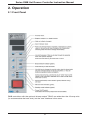
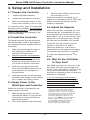
You can reach our technical
support team by phoning
216.367.7000 or visiting
www.ppe.com
II
Precautions
Warning
Use of this equipment in a manner not specified by the
manufacturer may impair protection provided by the equipment.
In addition to presenting a potential fire hazard, high voltage and
high temperature can damage equipment and cause severe injury
or death. When installing or using this instrument, follow all
instructions carefully and use approved safety controls.
Hazardous potentials exist on components inside the mainframe
and controller. Always disconnect AC power to the mainframe
when servicing the controllers or the mainframe.
Because these temperature controls or associated equipment
may not always fail safe, an approved temperature and/or
pressure safety control should be used for safe operation.
The controller power switch must be in the “OFF” position before
you put a controller into an energized mainframe, or remove a
controller from an energized mainframe.
Turn off power to the controller before cleaning the exterior of
the controller.
Failure to observe these precautions can result in exposure to a
potentially lethal shock hazard.
Changing DIP switch and jumper settings, and all wiring should
be done by an experienced technician. The controller and wiring
should be installed in accordance with national and local
electrical codes. To avoid serious personal injury and damage to
equipment, follow all warnings and cautions provided in the
manual supplied with the mainframe.
Littlefuse® is a registered trademark of Littlefuse, Inc.
Bussmann® is a registered trademark of Cooper Industries, Inc.
III
Caution
If a controller shows signs of having been damaged during
shipping, do not power up or install the controller. Save all
packing materials and report any damage to the carrier
immediately.
When the controller is powered up, the output may be activated.
Consider the effects on your process before powering up the
controller.
We recommend placing the controller in standby mode before
changing tuning parameter values manually. The output is off in
standby mode.
Do not locate this instrument where it may be subjected to
excessive shock, vibration, dirt, moisture, oil, or other liquids.
This is a Class A product. In domestic environments this product
may cause radio interference in which case the user may be
required to take adequate measures.
Specified operating ambient temperature is 32 to 131 °F
(0 to 55 °C).
Notes on CE EMC Compliance
This unit is compliant with the following standards when properly
installed into a grounded metal housing. EMC testing was
conducted with a load of 1 amp and setpoint of 400°F.
EMC directive (89/336/EEC)
EN 50081-1 (1992 edition)
EN 50082-1 (1992 edition)
Low Voltage Directive (73/23/EEC)
EN 61010-1 (1992 edition, Amendments 1, 2, 3, 4 and 11)
IV
Table of Contents
Precautions. . . . . . . . . . . . . . . . . . . . . . . . . . . . . . . . . . . . . . . . . . . . . . . . . . . . . I
1
Introduction . . . . . . . . . . . . . . . . . . . . . . . . . . . . . . . . . . . . . . . . . . . . . . . . 1
1.1
1.2
1.3
2.
Operation . . . . . . . . . . . . . . . . . . . . . . . . . . . . . . . . . . . . . . . . . . . . . . . . . . 5
2.1
2.2
2.3
2.4
3.
Prepare the Controller . . . . . . . . . . . . . . . . . . . . . . . . . . . . . . . . . . . . . . . . . . . 10
Install the Controller . . . . . . . . . . . . . . . . . . . . . . . . . . . . . . . . . . . . . . . . . . . . . 10
Apply Power to the Mainframe and Controller . . . . . . . . . . . . . . . . . . . . . . . . . 10
Adjust the Setpoint . . . . . . . . . . . . . . . . . . . . . . . . . . . . . . . . . . . . . . . . . . . . . . 10
Wait for the Controller to Tune Itself . . . . . . . . . . . . . . . . . . . . . . . . . . . . . . . . . 10
Error Messages and Codes . . . . . . . . . . . . . . . . . . . . . . . . . . . . . . . . . . 11
5.1
5.2
5.3
5.4
5.5
5.6
5.7
5.8
6.
Factory Switch Settings . . . . . . . . . . . . . . . . . . . . . . . . . . . . . . . . . . . . . . . . . . . 9
Setup and Installation . . . . . . . . . . . . . . . . . . . . . . . . . . . . . . . . . . . . . . . 10
4.1
4.2
4.3
4.4
4.5
5.
Front Panel . . . . . . . . . . . . . . . . . . . . . . . . . . . . . . . . . . . . . . . . . . . . . . . . . . . . . 5
What Happens When You Power Up the Controller . . . . . . . . . . . . . . . . . . . . . . 6
Operation Basics. . . . . . . . . . . . . . . . . . . . . . . . . . . . . . . . . . . . . . . . . . . . . . . . . 6
Manual Tuning. . . . . . . . . . . . . . . . . . . . . . . . . . . . . . . . . . . . . . . . . . . . . . . . . . . 7
Setting Switches . . . . . . . . . . . . . . . . . . . . . . . . . . . . . . . . . . . . . . . . . . . . 9
3.1
4.
About This Manual . . . . . . . . . . . . . . . . . . . . . . . . . . . . . . . . . . . . . . . . . . . . . . . 1
Features and Benefits of RMB Controllers . . . . . . . . . . . . . . . . . . . . . . . . . . . . . 1
Specifications . . . . . . . . . . . . . . . . . . . . . . . . . . . . . . . . . . . . . . . . . . . . . . . . . . . 4
Introduction . . . . . . . . . . . . . . . . . . . . . . . . . . . . . . . . . . . . . . . . . . . . . . . . . . . . 11
Summary of Error Codes . . . . . . . . . . . . . . . . . . . . . . . . . . . . . . . . . . . . . . . . . 11
Ground Fault in Controller Output Wiring . . . . . . . . . . . . . . . . . . . . . . . . . . . . . 13
Loop Break in Sensor Wiring . . . . . . . . . . . . . . . . . . . . . . . . . . . . . . . . . . . . . . 13
Open Thermocouple . . . . . . . . . . . . . . . . . . . . . . . . . . . . . . . . . . . . . . . . . . . . . 13
Reversed Thermocouple Leads . . . . . . . . . . . . . . . . . . . . . . . . . . . . . . . . . . . . 13
Heater Current Monitoring . . . . . . . . . . . . . . . . . . . . . . . . . . . . . . . . . . . . . . . . 14
Autotune Errors. . . . . . . . . . . . . . . . . . . . . . . . . . . . . . . . . . . . . . . . . . . . . . . . . 14
Maintenance . . . . . . . . . . . . . . . . . . . . . . . . . . . . . . . . . . . . . . . . . . . . . . . 15
6.1
6.2
6.3
6.4
Introduction . . . . . . . . . . . . . . . . . . . . . . . . . . . . . . . . . . . . . . . . . . . . . . . . . . . . 15
Cleaning the Front Panel . . . . . . . . . . . . . . . . . . . . . . . . . . . . . . . . . . . . . . . . . 15
Replacing the Fuses . . . . . . . . . . . . . . . . . . . . . . . . . . . . . . . . . . . . . . . . . . . . . 16
Unit Repairs . . . . . . . . . . . . . . . . . . . . . . . . . . . . . . . . . . . . . . . . . . . . . . . . . . . 16
i
Series RMB Hot Runner Controller Instruction Manual
7. Frequently Asked Questions . . . . . . . . . . . . . . . . . . . . . . . . . . . . . . . . . 17
7.1
7.2
Introduction . . . . . . . . . . . . . . . . . . . . . . . . . . . . . . . . . . . . . . . . . . . . . . . . . . . . 17
FAQs . . . . . . . . . . . . . . . . . . . . . . . . . . . . . . . . . . . . . . . . . . . . . . . . . . . . . . . . . 17
Index . . . . . . . . . . . . . . . . . . . . . . . . . . . . . . . . . . . . . . . . . . . . . . . . . . . . . . . . .18
ii
Series RMB Hot Runner Controller Instruction Manual
1. Introduction
1.1 About This Manual
This manual contains all the information
needed to set up and operate the Series
RMB Hot Runner controllers.
An orange LED on the front panel
indicates heater on, and a red LED
indicates high or low process alarm.
Green LEDs signal current mode and
boost action.
Instructions for wiring, installing, and
troubleshooting the controllers are in the
manual supplied with the mainframe.
Front panel keys make it easy to change
mode, change setpoint (normal mode),
output % (manual mode), and to activate
the boost. You can also use the front
panel to change tuning parameter values.
1.2 Features and Benefits
of RMB Controllers
1.2.1 Introduction
RMB controllers with the optional 30 amp
output TRIAC are wider than the 15 amp
units (to accommodate the heat sink), but
the user interface is the same.
The Series RMB Hot Runner controllers
offer many advanced features designed
to increase productivity and ensure fast,
accurate, and repeatable mode
temperature control. Each unit is
designed to control one temperature
zone based on input from a J or K
thermocouple. The controllers are set at
the factory for J thermocouple input. To
use a K thermocouple, change a switchsetting; see 3.4.
Detailed instructions for using the front
panel are in Section 2.
1.2.2 Convenient User Interface
RMB controllers are equipped with a bright
two-line LED display that is easy to read
over wide viewing angles.
The process value is displayed on the top
line (three digits).
The lower line (four digits) displays your
choice of setpoint (normal mode), output
percentage (normal and manual), and
output current to the closest tenth of an
amp (normal and manual).
1
Series RMB Hot Runner Controller Instruction Manual
1.2.3 PID Control with
Autotuning
By default, a soft start is executed:
In normal (automatic) mode each Series
RMB controller uses a single TRIAC
output to implement Proportional-IntegralDerivative (PID) control. Tuning is
automatic.
By default, the Autotune operation is
executed once. If the Autotune is
successful, then Autotune is disabled.
You can stop the Autotune by pressing the
MODE key. This does not disable the
Autotune feature. If Autotune operation is
set to “once”, then the controller attempts
to perform the Autotune operation each
time the controller is powered up, until a
successful Autotune is completed.
•
every time the controller starts
and the process value is less than
200°F (93°C), and
•
every time the controller is
returned to normal (automatic)
operation and the PV is less than
200°F (93°C).
•
any time a ground fault is detected;
see 1.2.7.6
You can set SW2-switch 1 to OFF as
described in Section 3 to cause the
controller to execute a soft start only in
response to detection of a ground fault
interruption. More information about the
start up sequence is in 2.2.
1.2.5 Boost Function
You can disable Autotune entirely or
enable it for every power up. To change
the Autotune setting, use the Pid menu.
You can also use the Pid menu to change
the proportion band and rate manually;
see 2.4.
Every Series RMB Hot Runner controller
supports a boost function that is activated
when you press the BOOST key. For the
next 15 seconds (or until you press the
BOOST key again, whichever is sooner),
20% more power is added to the controller
output (100% output maximum).
1.2.4 CompuStep™ Soft Start
for Heater Bake Out
1.2.6 Process Protection
Features
All Series RMB Hot Runner controllers
support the CompuStep soft start feature
to extend the life of the heaters and the
molds. The soft start allows slow
dissipation of moisture in heaters by
gradually applying power to the heaters.
1.2.6.1 Deviation Alarms
Each Series RMB Hot Runner controller
supports two deviation alarms. If the
process value falls below the setpoint
minus 30°F (17°C), or if the process
value exceeds the setpoint plus 30°F
(17°C), the red ALARM LED on the front
panel of the controller lights. The alarm
status indicator remains lit as long as the
process value deviates from the setpoint
by at least 30°F (17°C).
When a soft start is executed, phase angle
firing starts at 5% output power and steps
up the output 5% every 30 seconds.
The soft start lasts five minutes or until
the process temperature reaches
200°F (93°C).
The green NORMAL LED flashes during
soft start in normal (auto) mode. You can
stop the soft start by pressing the MODE
key.
2
Series RMB Hot Runner Controller Instruction Manual
1.2.6.6 Ground Fault Detection
Circuit
1.2.6.2 Loop Break Detection
The controller monitors the input change.
If the input value does not change within
999 seconds while the controller is
operating in normal (automatic) mode and
a “bad heater” error has not been detected
(see 1.2.7.5), then the controller signals a
loop break as described in 5.4 and the
controller goes to manual mode with 0%
output, which can then be adjusted.
An RMB controller can detect ground
faults in the controller output. When a
ground fault is detected, the controller
attempts to perform a normal soft start, if
the process value is less than or equal to
200°F (93°C).
The controller performs the soft start up to
three times if necessary. If the ground
fault is detected again after the soft start
has been executed three times, the
controller signals a “hard” ground fault;
see 5.2.
1.2.6.3 Sensor Error Monitoring
The controller can detect a reversed
sensor or open sensor. The controller
action when a sensor problem is detected
depends on the type of error and the
mode of the controller; see 5.4 and 5.5 for
details.
1.2.7 Ease of Setup
DIP switches make it easy to change the
input type and unit of measure. The
defaults are J thermocouple, with degrees
Fahrenheit for North America and degrees
Celsius for other shipping destinations.
1.2.6.4 Heater Current
Monitoring
The present current output to the heater,
expressed to the closest tenth of an amp,
is always displayable in the lower line.
Cycle through the available lower line
display items using the DISPLAY key.
The controller tunes itself automatically.
However, you can use the controller’s
front panel to change the proportional
band and rate manually; see 2.4.
1.2.6.5 Output Interruption
Check
An RMB controller constantly checks
heater current readings to ensure that
they correlate with output activity. If a
TRIAC short or bad heater is detected, the
output failure interruption relay breaks the
connection between the controller’s
TRIAC output and the heater. An error
message is also displayed; see 5.6.
3
Series RMB Hot Runner Controller Instruction Manual
1.3 Specifications
1.3.1
Operating Limits
Ambient Temperature 32°F to 131°F (0°C to 55°C)
Relative Humidity Tolerance 10 to 95% Non-Condensing
Shipping Temperature –40°F to 158°F (–40°C to 70°C)
Power Requirements 115 to 240 Vac 50 or 60 Hz nominal, CE compliant
1.3.2
Performance
Accuracy ± 0.3% of span
Setpoint Resolution 1 degree Fahrenheit
Repeatability ± 0.1% of span
Temperature Stability ± 0.5% of full scale over the ambient range of 32°F to
131°F (0°C to 55°C)
Thermocouple Cold-End Tracking automatic, better than 0.02°F per °F
(0.01°C per °C)
Noise Rejection Common Mode > 100 dB, Series Mode > 70 dB
Process Sampling Rate 10 Hz (100 ms)
1.3.3
Connections and Mounting
The Series RMB controllers are designed for installation in a Hot Runner
mainframe (or other compatible mainframe). Removal of an RMB controller
from the mainframe requires removal of a locking pin (standard controllers) or
locking screw (CE-compliant controllers).
1.3.4
Inputs
Thermocouple J or K
Supported Sensor Range 32 to 999°F (0 to 537°C)
1.3.5
Output
TRIAC, 15 amps at 120/240 Vac (30 amp optional), driven by optically isolated
interface circuit. Protected with a pair of 15 amp (or one 30 amp) fieldreplaceable fuses. Instructions for replacing the fuses are in 6.3. Replacement
fuses must be Type F fast-acting 250 Vac fuses rated at 15 amps (or 30 amps).
A 15 amp (120/240 Vac) relay (30 amp optional) interrupts power to the heater if
the controller detects shorting of the TRIAC output or other system failures.
A ground fault detection circuit is also standard.
4
Series RMB Hot Runner Controller Instruction Manual
2. Operation
2.1 Front Panel
RMB controllers with the optional 30 amp output TRIAC are wider than the 15 amp units
(to accommodate the heat sink), but the user interface is the same.
5
Series RMB Hot Runner Controller Instruction Manual
2.2 What Happens When
You Power Up the
Controller
2.3 Operation Basics
2.3.1 See PV
To see the process value: Look at the
top line of the display for the PV. The top
line shows the PV, unless the controller
detects an error, or Autotune is active, or
you are in the Pid menu.
Turn on the controller by pressing the “I”
end of the 16 A power switch on the front
panel. When an RMB controller is
powered up, it lights all segments of the
display briefly, then displays its firmware
level. 1
2.3.2 See if Output is On
The sequence of controller actions that
follow and the state of the controller output
depend on:
•
•
To see if the output is on: Look at the
HEAT LED. It is on when the output is on.
2.3.3 Monitor for Alarms
SW2-switch 1 setting–If SW2-switch
1 is ON (the default), the controller
does a CompuStep soft start if the
process value is less than or equal to
200°F (93°C). If SW2-switch 1 is
OFF, the controller does not do a soft
start at power up.
To watch for process alarms: Look at
the red ALARM LED. If the process value
falls 30°F (17°C) below the setpoint or
increases to 30°F (17°C) above the setpoint, the ALARM LED lights. It stays lit as
long as the PV deviates from the setpoint
by at least 30°F (17°C).
PId (PID control) menu’s At.OP
2.3.4 Change Mode
(Autotune operation) parameter
value–If the value of At.OP the
default oncE (once) or EnA (always
enabled), Autotune is attempted.
To change the mode: Press MODE
repeatedly until the LED lights for the
mode you want. The modes are:
You can stop soft start and Autotune by
pressing the MODE key repeatedly.
•
•
•
1
It is a good idea to make a note of the
firmware version number. If you phone for
technical support, you will be asked for this
version information, as well as for the
complete model number of the controller in
question.
6
normal (closed loop control) –
Controller uses the input value to cal
culate the output needed to maintain
the setpoint shown on the lower line.
manual (open loop control) –
Controller output is the percent
shown on the lower line. Input is
ignored. Transfer from normal to
manual is “bumpless” when the
process value is within 9°F (5°C)
of the setpoint.
standby – Standby output 0P
(zero percent) is on the lower line.
Series RMB Hot Runner Controller Instruction Manual
2.3.5 View Setpoint, Output,
and Current
2.4 Manual Tuning
To cycle through the lower line
displays: Press the DISPLAY key
repeatedly.
Manual tuning is usually not necessary.
By default an RMB controller Autotunes
the first time it is powered up. If the
Autotune is not successful, the controller
will try to Autotune every time it is powered
up until Autotune is successful. Autotune
is then disabled automatically.
•
•
2.4.1 Usually Not Needed
In normal mode you can cycle
through the setpoint, output
percent (with P), and heater
current to the closest tenth of an
amp (with A).
In manual mode you can switch
between output percent (with P)
and heater current to the closest
tenth of an amp (with A).
2.4.2 PID Control
With PID control the device modulates
output power by adjusting the output
power percentage within a proportional
band. Power is proportionally reduced as
the process temperature gets closer to the
setpoint temperature.
2.3.6 Change Setpoint or
Output
The derivative action affects the output
based on the rate of change of the
process value.
To change the setpoint (normal mode)
or output (manual mode): Press
DISPLAY until the setpoint or manual
mode output is on display. Press the or
▼ key until the displayed value has been
changed to the new value you want.
▼
You can use the Pid menu to change the
Pb (proportional band) and rAtE
(derivative) values.
The output current value and normal mode
output percentage are read-only.
The integral action (reset) affects the output based on the duration of the process
value’s variation from the setpoint. In the
Series RMC Hot Runner controllers, the
integral (reset) action is always equal to
five times the derivative (rate) action.
2.3.7 Start Boost
To start the boost: Press the BOOST
key. The LED above the BOOST key
lights. For the next 15 seconds (or until
you press the BOOST key again,
whichever is sooner), 20% is added to the
controller output (100% output maximum).
You can also use the Pid menu to
change the setting of the At.OP (Autotune
operation) parameter, which determines
when Autotuning is attempted.
7
Series RMB Hot Runner Controller Instruction Manual
2.4.3 Changing Tuning
Parameters Values
Manually
At this point you can:
Put the controller in standby by
pressing the MODE key until the
STANDBY LED is lit.
2.
Access the tuning menu by pressing
and holding the DISPLAY key until
Pid is displayed on the top line
(approximately 3 seconds).
3.
Display the first parameter in the
menu by pressing the MODE key.
The second line of the display will
show Pb (proportional band), the
name of the first parameter in the
menu, alternating with the current
value.
Pid
pb
5.
6.
with
•
if you like the current value of the
parameter on display, you can press
the MODE key to leave the displayed
value unchanged and go on through
the parameters in the menu, or
•
exit the Pid menu by pressing and
holding the DISPLAY key until the
normal operating display returns to
view, and then press MODE to return
to normal mode.
If you do not press any key, eventually you
will be timed out of the Pid menu. The
controller will revert to the operational
display that was in view before you
entered the menu. The value that was on
display when you were timed out of the
menu will be saved to the controller’s
database automatically.
Pid
24
2.4.4
If this is not the parameter you want
to change, press MODE repeatedly
until you see the parameter you want.
Pid Menu Parameters
Pb (proportional band) – Valid range is 0.1
to 999°F (0 to 537°C). Default is 24°F
(13°C).
▼
4.
alternating
change the value of the newly dis
played parameter with the and
▼ keys, or
▼
To change a tuning parameter value
manually:
1.
•
Use the ▼ and keys to change a
numeric value or scroll through the
choices.
rAtE (derivative) – The valid range is 0.0
to 999 seconds. Default is 7 seconds.
When the desired choice or numeric
value is on display, press the MODE
key once. The displayed choice or
value will be written to the controller’s
database. The next parameter in the
menu (or the first parameter if you
were at the end of the menu) will be
displayed.
At.OP (Autotune operation) – Choices are:
d IS Autotune disabled
oncE Autotune once at next power up,
then disable if Autotune was
successful.
EnA
8
Autotune enabled every time
controller is powered up.
Series RMB Hot Runner Controller Instruction Manual
3.1 Setting Switches
The factory switch settings are shown
below.
Location of DIP Switches
SW2-switch 1 – OFF for soft start only
when ground fault has been detected;
ON (default) for soft start every time
controller is powered up.
SW2-switch 2 – OFF (default) for J
thermocouple input; ON for K
thermocouple.
SW2-switch 3 – OFF for degrees
Fahrenheit; ON for degrees Celsius.
Default depends on shipping destination:
OFF for North America
ON for all other destinations.
SW2-switch 5 – OFF (default) for normal
operation; ON to load default parameter
values the next time controller is powered
up.
SW2-switch 8 – OFF – Normal
ON – Loop Break Disabled
SW2-switch 4 is used only at the factory.
SW2-switches 6, 7, and 8 are not used.
Leave them off.
9
Series RMB Hot Runner Controller Instruction Manual
4. Setup and Installation
4.1 Prepare the Controller
Unpack the RMB controller.
2.
Inspect the controller for damage.
3.
When the controller is powered up, all
segments of the display and all LEDs light
briefly, and then the firmware version
number is displayed.
Make sure the power switch on the
front of the controller is set to off (O).
If a controller shows signs of having been
damaged during shipping, do not install or
power up the controller. Save all packing
materials and report any damage to the
carrier immediately.
4.4 Adjust the Setpoint
When the controller is powered up, it will
automatically do a CompuStep soft start
for heater bake out if the process value is
below 200°F. (PV is on the top line of the
display. SP is on the lower line.) During
the soft start the NORMAL LED flashes.
4.2 Install the Controller
This guide assumes that the mainframe
has already been wired as described in
the installation manual supplied with the
mainframe.
1.
Make sure the plunger in center of
the locking pin is pulled out (or
loosen the locking screw).
2.
With the controller and mainframe
power switches set to off (O), align
the RMB controller’s printed circuit
board with the guide channels in a
slot in the Hot Runner mainframe.
3.
Slide the controller into the main
frame until the RMB connectors are
firmly seated in the backplane of
the mainframe.
4.
Lock the controller into the frame by
pressing in the plunger on the locking
pin (or tighten the locking screw).
During the soft start (which lasts five
minutes or until the PV is 200°F),
adjust the setpoint to a value that is
representative of the setpoint you expect
to use when the controller is in service. 2
To adjust the setpoint press the
▼ key.
New RMB controllers are set to do a soft
start every time they are powered up (if
the PV is less than 200°F), and then to do
an Autotune operation each time the
controller is powered up until a successful
Autotune is completed.
If you are setting up a new process,
Autotune all the RMB controllers in the
process simultaneously, so that interactions between zones during tuning
When the controller is powered up, the
output may be activated.
Before powering up the controller,
consider the effects on your process
if the output is activated. Take sitespecific precautions.
2.
Turn on the power to the mainframe.
or
4.5 Wait for the Controller
to Tune Itself
4.3 Apply Power to the
Mainframe and Controller
1.
Set the power switch on the front of
the controller to on (I).
▼
1.
3.
2
If the PV is greater than 200°F, then the
controller will skip the soft start, and will
Autotune as soon as you power up the controller the first time. However, the tuning will
not be valid, because you have not yet
entered the appropriate setpoint for your
process. Press MODE once to interrupt the
Autotune. With the controller in normal
mode (NORMAL LED lit), adjust the setpoint, and then cycle power to start
Autotune again with a valid setpoint.
10
Series RMB Hot Runner Controller Instruction Manual
The display reverts to the normal mode
operating display: PV on top line, SP on
lower line. The proportional band and rate
values calculated by the controller during
the Autotune have been saved. (The
integral (reset) action for PID control is
always set to five times the rate value in
an RMB controller.) Autotune is disabled.
(If the Autotune is not successful, output
goes to 0%, and you will see an error
code; see 5.8.)
parallel the interactions expected while the
controllers are in use.
If you need to stop the Autotune, press the
MODE key until the controller is in
standby. (When you are ready to
Autotune, cycle the power to the
controller.)
If you are installing a single replacement
controller, let the Autotune proceed without
interruption. During Autotune, the process
value alternates with tun.
RMB controllers do not require calibration.
At the conclusion of a successful
Autotune, the flashing tun disappears.
The controller is ready to use.
5. Error Messages and Codes
5.2 Summary of Error
Codes
5.1 Introduction
Usually the controller displays the process
variable on the top line and the setpoint on
the lower line of the display. You can see
other values on the lower line by pressing
the DISPLAY key.
If the controller detects a problem, the
highest priority error will be displayed.
The possible errors and suggested
operator actions in response are
summarized below.
However, when the controller detects a
problem with the input or output, or with its
own operation, messages and codes are
displayed to alert you to conditions that
require your immediate attention.
Displayed Code
or Message
When one of these error codes is displayed, the output is 0%. In the case of
the Out SHrt (output short) and bAd Htr
(bad heater) errors, the output failure relay
interrupts the output.
Error Condition
Operator Action
Highest Priority – Controller has detected a problem with its own operation. All errors of this type
shut down controller activity (except for display of error message).
Err
0100
Err
0101
Err
0202
PROM checksum error
Cycle power to clear the message.
Note the error code and call for service.
RAM error
Cycle power to clear the message.
Note the error code and call for service.
Default Pid menu parameter
values were loaded
automatically, because the
controller found corrupted
values stored on the EEPROM.
(This message is not displayed
when you use SW2-switch 5 to
set the default values
intentionally.)
Cycle power to clear the message.
Because the At.OP (Autotune
operation) value will be set to “once”,
the controller will tune itself.
11
Series RMB Hot Runner Controller Instruction Manual
Displayed Code
or Message
Error Condition
Operator Action
Err
0249
Err
0303
Calibration value corrupted.
Cycle power to clear the message.
Note the error code and call for service.
EEPROM write failure occurred.
Cycle power to clear the message.
Try again to save a Pid menu
parameter value. If the message
recurs and persists, the EEPROM
may be worn out. Call for service.
Err
2436
The controller could not
determine whether the power
frequency is 50 Hz or 60 Hz.
Cycle power to clear the message.
Check the line frequency. If it is OK,
but the message recurs and persists,
call for service.
Err
3923
throu9h
3543
Interrupt-related problem
occurred.
Cycle power to clear the message.
If the message recurs and persists,
call for service.
High Priority – PV is displayed on top line, unless an input error (medium priority) occurs
simultaneously. In that case, the top line is blank; no valid PV is available. If two high priority error
states are detected, the one ranked highest will be displayed on the lower line (see numbers below).
1)
9FI
Hard ground fault detected
(see 5.2).
2)
bAd Htr
Heater problem detected
(see 5.7).
3)
Out SHrt
Output is off, but current flow is
detected (see 5.7).
4)
LPbr
PV has not increased at least
1% of supported sensor span in
999 seconds (loop break time;
see 5.4).
5)
Ht.rd Err
Heater conversion error occurred.
Turn off controller. Fix the problem.
Turn on the controller.
Cycle power to clear the message.
Call for service.
Medium Priority – SV is displayed on lower line. These conditions cannot occur simultaneously.
tC oPn
Thermocouple is open (see 5.5).
tC rEu
Thermocouple leads are
reversed (see 5.6).
If the condition is fixed, the message
will clear automatically. To clear the
message manually, cycle the power.
Low Priority – SV is displayed on lower line. Output goes to 0%. Only one Autotune error will be
displayed.
tun
tun
tun
tun
Er3
Er5
Er8
Er9
Autotune error; see 5.8 for details.
12
Series RMB Hot Runner Controller Instruction Manual
5.3 Ground Fault in
Controller Output Wiring
The controller remains in this alarm and
output off state until you cycle power to
the controller.
The RMB controller detects ground faults
in the controller output wiring by
monitoring the current to ground. If the
current to ground is 55 mA or higher, the
controller attempts to perform a normal
soft start if the process value is less than
or equal to 200°F (93°C). The standard
CompuStep soft start described in 1.2 is
executed. In this special case, the soft
start will be executed up to three times. If
the ground fault is still detected, the
controller considers this a “hard” ground
fault.
5.5 Open Thermocouple
If the controller detects an open sensor:
•
•
When a hard ground fault is detected, the
controller:
interrupts the signal to its own output,
in effect “turning off” the output, and
•
an error message 9FI is displayed on
the lower line, and
•
•
the appropriate output action is taken,
depending on control mode:
•
if the controller is in normal (auto)
mode, the output goes to 0% for
approximately one second, and then
the controller uses a calculated out
put value, based on stored output
values that have successfully
maintained the current setpoint for
your process in the past
•
if the controller is in manual mode,
the output remains at the percent in
use when the open sensor was
detected
5.6 Reversed Thermocouple
Leads
Following the interrupt in response to a
“hard” ground fault, the controller’s output
remains off until you cycle power to the
controller.
If the controller detects a reversed sensor:
5.4 Loop Break in Sensor
Wiring
If the input value does not change at least
1% of supported sensor span (9.67°F or
5.37°C) within 999 seconds while the
controller output is on, and a “bad heater”
error has not been detected (see 5.6),
then:
the controller output goes to 0%, and
•
the red ALARM LED lights (all
other LEDs off), and
•
the message
lower line.
tC and
The controller remains in this alarm and
failsafe state until the condition clears or
you cycle power to the controller.
the red ALARM LED lights (all other
LEDs off).
•
the upper display alternates
(open sensor), and
oPn
If a ground fault is detected when the
process value is greater than 200°F
(93°C), the controller considers it a “hard”
ground fault immediately.
•
the red ALARM LED lights (all other
LEDs off), and
•
the controller output goes to 0%, and
•
the red ALARM LED lights (all other
LEDs off), and
•
the upper display alternates
(reversed sensor).
tC and
rEu
The controller remains in this alarm and
output off state until the condition clears or
you cycle power to the controller.
LPbr is displayed on the
13
Series RMB Hot Runner Controller Instruction Manual
5.7 Heater Current
Monitoring
The present current output to the heater,
expressed to the closest tenth of an amp,
is always displayable in the lower line.
Cycle through the available lower line
display items using the DISPLAY key.
The controller constantly checks heater
current readings to ensure that they
correlate with output activity.
•
•
controller processing stops, and
•
the red ALARM LED lights (all other
LEDs off), and
•
an alarm message is displayed on
the lower line:
•
if a short was detected,
alternates with SHrt
•
if a heater problem is detected,
alternates with Htr
Out
bAd
If the output is off and a current flow
greater than 0.1 amp is detected,
then the controller posts a “TRIAC
short” error.
The controller remains in this halted state
until you cycle power to the controller.
If the output is on, but no controller
current output flow is detected, then
the processor posts a “bad heater”
error. (This condition is checked only
if no loop break has been detected
while the controller is in normal (auto)
mode, and the PV is not within the
proportional band.)
At the conclusion of an unsuccessful
Autotune, you will see Er plus a one-digit
error code (alternating with tun). If the
Autotune is not successfully completed,
the Autotune feature is not disabled
automatically.
5.8 Autotune Errors
An Autotune error code is displayed until
you press the MODE key. If the Autotune
operation is terminated by the controller
because of an error condition, the
controller output goes to 0%.
If either of these error conditions is
detected:
•
•
the output failure interruption relay
breaks the connection between the
controller’s TRIAC output and the
heater, and
Error Code
Autotune Errors
Description
Er3
Setpoint is higher than the process value. Look at the setpoint.
If it is realistic for your process, then check the thermocouple
leads; maybe they are reversed.
Er5
There is not enough difference between initial PV and the
setpoint. For Autotune to work, the difference must be at least
9°F (5°C).
Er8
The startup curve (change in PV) was not acceptable to the
Autotune algorithm. This could be caused by a process upset
that occurred during tuning. Try Autotuning again when the
process is stable. If the error recurs, your process is not
suitable for Autotuning. Use manual tuning; see 2.4.
Er9
The Autotuning timed out, because the process was
unresponsive (or extremely slow). Your process is not suitable
for Autotuning. Use manual tuning; see 2.4.
14
Series RMB Hot Runner Controller Instruction Manual
6. Maintenance
6.1 Introduction
This section contains instructions for cleaning the front panel of the controller
and instructions for replacing the fuses.
Except for fuses, the controller contains no user-serviceable parts.
Warning
Do not attempt to clean any part of a controller other than the
front panel.
If you want to clean the front panel of a single controller, use the
power switch on the front of the controller to turn it off, then
remove the controller from the mainframe.
If you want to clean the front panel of several controllers, turn
off all controllers in the mainframe and turn off power to the
mainframe before cleaning the controllers while they are in the
mainframe.
While cleaning a controller’s front panel, do not allow alcohol to
enter the switch.
Allow controllers and mainframes to dry thoroughly before
restoring power. Do not use a heater or compressed air to dry
the units.
Failure to observe these precautions can result in exposure to a
potentially lethal shock hazard.
The controller power switch should be in the “OFF” position
before you put a controller into an energized mainframe, or
remove a controller from an energized mainframe. Failure to
observe these precautions can result in damage to the
connectors and printed circuit boards.
6.2 Cleaning the Front
Panel
loosening the locking screw), and
pulling on the handle on the front of
the controller.
To clean an RMB controller:
1.
Read the safety warnings above
before you start cleaning a controller.
2.
To clean the front panel of a single
controller, put the controller power
switch in the “OFF” position, and then
remove the controller from the
energized mainframe by pulling out
the plunger on the locking pin (or
Alternatively, if you plan to clean the front
panel of several controllers, put the power
switch of every controller in the mainframe
in the “OFF” position, and then turn off
power to the entire mainframe. After the
mainframe has been de-energized, you
can clean the controllers while they are in
the mainframe.
15
Series RMB Hot Runner Controller Instruction Manual
3.
Use a cotton cloth to gently and
sparingly apply isopropyl alcohol to
the front panel of the controller. Do
not use cleaning solutions or other
solvents. Use of anything other than
isopropyl alcohol can result in
damage to the controller.
4.
Allow the controller to air-dry
thoroughly. Do not use a heater or
compressed air to dry the unit.
5.
Inspect all surfaces to make sure that
they are completely dry.
6.
When the controller is completely dry,
re-install it and return it to service.
Each RMB controller with 15 amp output
contains two fuses, located on the main
printed circuit board. An RMB with 30
amp output has one fuse on the main circuit board.
To replace the fuses in an RMB
controller:
Make sure that you have the correct
replacement fuse.
•
For RMB controller with 15 amp
output – Type F fast-acting 250
Vac fuses rated at 15 amps.
Suitable fuses are p/n
210B001U01 and Littlefuse Inc.
p/n 314015.
•
For RMB controller with 30 amp
output – Type F fast-acting 250
Vac fuse rated at 30 amps.
Suitable fuses are p/n
210A009U01 and Cooper
Bussmann FWX-30A14FB.
2.
Put the power switch of the controller
in the “OFF” position.
3.
Pull out the plunger in the locking pin
(or loosen the locking screw).
Replace the fuses.
6.
Re-install the controller and return it
to service.
It is recommended that units requiring
service be returned to an authorized
service center. Before a controller is
returned for service, please consult the
service center nearest you. In many
cases, the problem can be cleared up over
the telephone. When the unit needs to be
returned, the service center will ask for a
detailed explanation of problems
encountered and a Purchase Order to
cover any charge. This information should
also be put in the box with the unit. This
should expedite return of the unit to you.
6.3 Replacing the Fuses
1.
5.
6.4 Unit Repairs
Do not allow alcohol to enter the
power switch on the controller’s front
panel.
4.
Use the handle on the front of the
controller to pull it out of the
mainframe.
16
Series RMB Hot Runner Controller Instruction Manual
7. Frequently Asked Questions
7.1 Introduction
Before you call for technical support, please look at this section to see if your
question is covered here. If you do call for technical assistance, be ready to
supply the following information:
•
•
•
•
complete model number of controller (and firmware version if known)
symptoms of the problem
unusual events, if any, that preceded the problem
remedies you have already tried
7.2 FAQs
7.2.1 How do I change from a J to a K thermocouple?
Every Series RMB controller is shipped ready to accept input from a J thermo
couple. If you plan to use a K thermocouple for input, you must set
SW2-switch 2 to ON as described in Section 3. Read the safety warnings at
the front of this manual before changing switch settings.
7.2.2 Do I have to calibrate a new controller?
No
7.2.3 Why doesn’t the displayed PV match the value on a
thermometer in the process?
Unless the thermometer and the sensor providing input to the controller are very
close to one another, their readings will not match in some applications, because
of temperature variations within the process.
7.2.4 I turned on the power; why doesn’t the controller light up?
If SafeChange is enabled, but the mainframe does not support SafeChange, the
controller will not work. Instructions for checking to see if a mainframe supports
SafeChange are in 3.2.
17
Series RMB Hot Runner Controller Instruction Manual
Index
G
A
alarms, 2, 5, 6
At.OP parameter, 6, 7, 11
automatic mode. See normal mode
Autotune, 2, 6, 7, 10
Autotune errors, 12, 14
Autotune Operation parameter, 6, 7, 11
gFI error message, 13
ground fault detection, 3, 13
H
HEAT LED, 5, 6
heater conversion error, 12
heater current display, 7
heater current monitoring, 3
HT.rd Err message, 12
B
bad Htr error message, 14
boost, 5, 7
bumpless transfer, 6
I
input failure, 13
input switch setting, 3, 17
integral action, 2, 7, 11
interrupt (unexpected or invalid), 12
C
calibration, 11, 17
calibration value corrupted error, 12
CE EMC compliance, II
changing setpoint or output, 7
checksum error, 11
cleaning controllers, 15
CompuStep, 2, 3
current displayed, 3, 7
current monitoring, 3, 14
J
J thermocouple, switch setting for, 3, 10,
17
jumper setting, 9
K
K thermocouple, switch setting for, 3, 10,
17
D
L
default switch settings, 10
default values, 11
derivative action, 2, 7, 11
deviation alarms, 2, 5, 6
DISPLAY key, 5
displays, 5, 11
line frequency determination error, 12
loop break, 3, 13
LPbr error message, 3, 13
M
E
maintenance, 15
MANUAL LED, 5
manual tuning, 7
MODE key, 5
modes of operation, 2, 6
EEPROM write error, 12
error codes, 11
F
factory default switch settings, 10
factory default values, 11
front panel, 5
fuses, 16
18
Series RMB Hot Runner Controller Instruction Manual
N
S
NORMAL LED, 5
normal mode, 2
SafeChange feature, 9, 17
safety information, I, 15
sensor error, 3
sensor type, switch setting for, 3, 17
setpoint, 5, 7
soft start, 2, 3
span calibration, 17
STANDBY LED, 5
switch settings, 3, 9, 10, 17
O
open sensor, 13
Out Shrt error message, 14
output bad, 3, 14
output displayed, 7
output for control, 2, 6
output in manual mode, 7
output state on power up, 6
output TRIAC short error, 3, 14
T
tC oPn error message, 13
tC rEv error message, 13
technical support, 17
TRIAC short error message, 3, 14
troubleshooting, 11, 17
tuning, 7, 10
P
part number for fuses, 16
part number for SafeChange clip, 10
Pid menu, 2, 6, 7, 11, 12
powering up controller, 6
process value display, 5, 6
proportional band, 2, 7, 11
U
unit of measure switch setting, 9, 10
user interface, 5
user-serviceable parts, 15
R
Z
RAM error, 11
rate, 2, 7, 11
replacing fuses, 16
reset, 7, 11
reversed sensor, 13
zero calibration, 17
19
Series RMB Hot Runner Controller Instruction Manual
Two-Year Limited Warranty
THIS EQUIPMENT IS WARRANTED TO BE FREE FROM DEFECTS OF MATERIAL AND
WORKMANSHIP. IT IS SOLD SUBJECT TO OUR MUTUAL AGREEMENT THAT THE
LIABILITY OF ATHENA CONTROLS, INCORPORATED IS TO REPLACE OR REPAIR
THIS EQUIPMENT AT ITS FACTORY, PROVIDED THAT IT IS RETURNED WITH
TRANSPORTATION PREPAID WITHIN TWO (2) YEARS OF ITS PURCHASE.
THE PURCHASER AGREES THAT ATHENA CONTROLS, INCORPORATED ASSUMES
NO LIABILITY UNDER ANY CIRCUMSTANCES FOR CONSEQUENTIAL DAMAGES
RESULTING FROM ITS USE OR FROM IMPROPER HANDLING OR PACKAGING OF
SHIPMENTS RETURNED TO THE FACTORY.
COMPONENTS WHICH WEAR OR WHICH ARE DAMAGED BY MISUSE ARE NOT
WARRANTED. THESE INCLUDE CONTACT POINTS, FUSES, ELECTROMECHANICAL
RELAYS, AND TRIACS. UNITS WHICH HAVE BEEN MODIFIED BY A CUSTOMER IN
ANY WAY ARE NOT WARRANTED.
Other than those expressly stated herein, THERE ARE NO OTHER WARRANTIES OF
ANY KIND, EXPRESS OR IMPLIED, AND SPECIFICALLY EXCLUDED BUT NOT BY WAY
OF LIMITATION, ARE THE IMPLIED WARRANTIES OF FITNESS FOR A PARTICULAR
PURPOSE AND MERCHANTABILITY.
IT IS UNDERSTOOD AND AGREED THE SELLER’S LIABILITY WHETHER IN
CONTRACT, IN TORT, UNDER ANY WARRANTY, IN NEGLIGENCE OR OTHERWISE
SHALL NOT EXCEED THE RETURN OF THE AMOUNT OF THE PURCHASE PRICE
PAID BY THE PURCHASER AND UNDER NO CIRCUMSTANCES SHALL SELLER BE
LIABLE FOR SPECIAL, INDIRECT, INCIDENTAL OR CONSEQUENTIAL DAMAGES.
THE PRICE STATED FOR THE EQUIPMENT IS A CONSIDERATION IN LIMITING
SELLER’S LIABILITY. NO ACTION, REGARDLESS OF FORM, ARISING OUT OF THE
TRANSACTIONS OF THIS AGREEMENT MAY BE BROUGHT BY PURCHASER MORE
THAN ONE YEAR AFTER THE CAUSE OF ACTION HAS ACCRUED.
SELLER’S MAXIMUM LIABILITY SHALL NOT EXCEED AND BUYER’S REMEDY IS
LIMITED TO EITHER (i) REPAIR OR REPLACEMENT OF THE DEFECTIVE PART OR
PRODUCT, OR AT SELLER’S OPTION (ii) RETURN OF THE PRODUCT AND REFUND
OF THE PURCHASE PRICE, AND SUCH REMEDY SHALL BE BUYER’S ENTIRE AND
EXCLUSIVE REMEDY. THE SPECIFICATIONS PUT FORTH IN THIS MANUAL ARE
SUBJECT TO CHANGE WITHOUT NOTICE.
20
Series RMB Hot Runner Controller Instruction Manual
Notes
21
Plastic Process Equipment, Inc.
8303 Corporate Park Drive
Macedonia, OH 44056
1.800.321.0562 • 216.367.7000
FAX: 216.367.7022 • www.ppe.com
Part #900M212U00 RevA-05/06