1
Service Manual
Color Laser Printer
CLP-320/325 Series
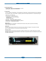
The keynote of Product
CLP-320/325/326/320N/321N/325W
- Model series : C
LP-320/325
CLP-320N/CLP-321N(Network model)
CLP-325W (Wireless model)
- Speed(Color/Mono) : 4/16 ppm(A4). 4/17ppm(Let)
- Printing resolution : Max. 2,400 x 600 dpi
- Emulation : SPL-C / PCL-6(Network Model)
- Memory : 3
2MB (USB Model)
256MB (Network/Wireless Model)
- Processor : Jupiter5(360MHz,CLP-320/325/320N/325W)
- Interface : IEEE 802.3,Ethernet(10/100Mbps)
Wireless: IEEE 802.11b/g(Only wireless model)
- Toner Cartridge
• Initial : 1K Toner(K), 0.7K Toner(C,M,Y, each)
• Sales : 1.5K Toner(K), 1K toner(C, M, Y each)
- Printer Life : 100,000 pages
Monthly Max. Duty : 20,000 pages/month
Contents
chapter 1 Precautions
1.1 Safety Warning……………………………………………………… 1-1
1.2 Caution for safety…………………………………………………… 1-2
1.3 ESD Precautions… ………………………………………………… 1-5
chapter 2 Product Overview
2.1 Product Specifications………………………………………………
2.1.1 Product Overview………………………………………………
2.1.2 Prouduct Specification…………………………………………
2.1.3 Model Comparison Table………………………………………
2.2 System Overview……………………………………………………
2.2.1 System Structure… ……………………………………………
2.2.2 Main PBA Description… ………………………………………
2.2.3 CRUM……………………………………………………………
2.3 S/W Structure and Descriptions……………………………………
2.3.1 Architecture… …………………………………………………
2.3.2 Language Monitor………………………………………………
2.3.3 Status Monitor… ………………………………………………
2.3.4 Network Interface………………………………………………
2.3.5 Printer Driver <-> Status Monitor… …………………………
2.3.6 System F/W Flow………………………………………………
2.3.7 CRUM Overview… ……………………………………………
2.3.8 Initailize Flow……………………………………………………
2-1
2-1
2-2
2-10
2-11
2-11
2-18
2-25
2-26
2-26
2-26
2-26
2-27
2-27
2-28
2-29
2-30
chapter 3 Disassembly and Reassembly
3.1 Precautions when replacing parts…………………………………
3.1.1 Precautions when assembling and disassembling… ………
3.1.2 Preautions when handling PBA… ……………………………
3.1.3 Releasing Plastic Latches… …………………………………
3.2 Parts for Maintenance and Repair…………………………………
3-1
3-1
3-1
3-1
3-2
Contents
3.2.1 Replacement interval for parts with a limited life……………
3.2.2 Printer Cleaning…………………………………………………
3.3 Information Related to Disassembly and Assembly… …………
3.3.1 Special service parts… ………………………………………
3.3.2 Screws used in the printer… …………………………………
3.4 Disassembly Procedure… …………………………………………
3.4.1 Cover… …………………………………………………………
3.4.2 ITB… ……………………………………………………………
3.4.3 Fuser unit… ……………………………………………………
3.4.4 HVPS board… …………………………………………………
3.4.5 Main PBA… ……………………………………………………
3.4.6 SMPS board… …………………………………………………
3.4.7 LSU………………………………………………………………
3.4.8 Holder Pad………………………………………………………
3.4.9 Transfer roller……………………………………………………
3.4.10 OPE PBA………………………………………………………
3.4.11 Pick up roller… ………………………………………………
3-2
3-3
3-4
3-4
3-5
3-7
3-7
3-9
3-9
3-10
3-11
3-11
3-12
3-12
3-13
3-14
3-15
chapter 4 Alignment and Troubleshooting
4.1 Alignment and Adjustments…………………………………………
4.1.1 Control Panel……………………………………………………
4.1.2 Jam Removal……………………………………………………
4.1.3 Firmware upgrade………………………………………………
4.1.4 Periodic Defective Image………………………………………
4.1.5 Using the smart pane program… ……………………………
4.1.6 How to use EDC (Engine Diagnostic Control) Mode… ……
4.2 Troubleshooting……………………………………………………
4.2.1 Procedure of Checking the Symptoms… ……………………
4.2.2 Troubleshooting Checklist… …………………………………
4.2.3 Solving General Printing Problems… ………………………
4.2.4 Solving Print Quality Problems… ……………………………
4.2.5 Common Windows Problems…………………………………
4.2.6 Common Macintosh Problems… ……………………………
4-1
4-1
4-9
4-13
4-14
4-15
4-17
4-22
4-22
4-23
4-24
4-32
4-50
4-51
Contents
4.2.7 Common Linux Problems… ………………………………… 4-52
4.2.8 Major Problems Trouble shooting… ………………………… 4-56
chapter 5 System Diagram
5.1 Block Diagram… …………………………………………………… 5-1
5.2 Connection Diagram……………………………………………… 5-2
chapter 6 Reference Information
6.1
6.2
6.3
6.4
Tool for Troubleshooting… …………………………………………
Acronyms and Abbreviations… ……………………………………
Select a location for the printer… …………………………………
A4 ISO 19798 Standard Pattern……………………………………
attached Parts Catalog
6-1
6-2
6-4
6-5
Precautions
1. Precautions
In order to prevent accidents and damages to the equipment please read the precautions listed below
carefully before servicing the product and follow them closely.
1.1 Safety warning
(1) Only to be serviced by a factory trained service technician.
High voltages and lasers inside this product are dangerous. This product should only be serviced by a
factory trained service technician.
(2) Use only Samsung replacement parts.
There are no user serviceable parts inside the product. Do not make any unauthorized changes or
additions to the product as these could cause the product to malfunctions and create an electric shocks
or fire hazards.
(3) Laser Safety Statement
The product is certified in the U.S. to conform to the requirements of DHHS 21 CFR, chapter 1
Subchapter J for Class 1(1) laser products, and elsewhere, it is certified as a Class I laser product conforming to the requirements of IEC 825. Class I laser products are not considered to be hazardous. The
laser system and product are designed so there is never any human access to laser radiation above a
Class I level during normal operation, user maintenance, or prescribed service condition.
Warning >> Never operate or service the product with the protective cover removed from Laser/Scanner
assembly. The reflected beam, although invisible, can damage your eyes.
When using this product, these basic safety pre-cautions should always be followed to reduce
risk of fire, electric shock, and personal injury.
Service Manual
1-1
Samsung Electronics
Precautions
1.2 Caution for safety
1.2.1 Toxic material
This product contains toxic materials that could cause illness if ingested.
(1) If the LCD control panel is damaged, it is possible for the liquid inside to leak. This liquid is toxic.
Contact with the skin should be avoided. Wash any splashes from eyes or skin immediately and contact
your doctor. If the liquid gets into the mouth or is swallowed, see a doctor immediately.
(2) Please keep imaging unit and toner cartridge away from children. The toner powder contained in the
imaging unit and toner cartridge may be harmful, and if swallowed, you should contact a doctor.
1.2.2 Electric shock and fire safety precautions
Failure to follow the following instructions could cause electric shock or potentially cause a fire.
(1) Use only the correct voltage, failure to do so could damage the product and potentially cause a fire or
electric shock.
(2) Use only the power cable supplied with the product. Use of an incorrectly specified cable could cause the
cable to overheat and potentially cause a fire.
(3) Do not overload the power socket, this could lead to overheating of the cables inside the wall and could
lead to a fire.
(4) Do not allow water or other liquids to spill into the product, this can cause electric shock. Do not allow
paper clips, pins or other foreign objects to fall into the product, these could cause a short circuit leading
to an electric shock or fire hazard.
(5) Never touch the plugs on either end of the power cable with wet hands, this can cause electric shock.
When servicing the product, remove the power plug from the wall socket.
(6) Use caution when inserting or removing the power connector. When removing the power connector, grip it
firmly and pull. The power connector must be inserted completely, otherwise a poor contact could cause
overheating possibly leading to a fire.
(7) Take care of the power cable. Do not allow it to become twisted, bent sharply around corners or wise
damaged. Do not place objects on top of the power cable. If the power cable is damaged it could overheat
and cause a fire. Exposed cables could cause an electric shock. Replace the damaged power cable
immediately, do not reuse or repair the damaged cable. Some chemicals can attack the coating on the
power cable, weakening the cover or exposing cables causing fire and shock risks.
(8) Ensure that the power sockets and plugs are not cracked or broken in any way. Any such defects should
be repaired immediately. Take care not to cut or damage the power cable or plugs when moving the
machine.
(9) Use caution during thunder or lightning storms. Samsung recommends that this machine be disconnected
from the power source when such weather conditions are expected. Do not touch the machine or the
power cord if it is still connected to the wall socket in these weather conditions.
(10) Avoid damp or dusty areas, install the product in a clean well ventilated location. Do not position the
machine near a humidifier or in front of an air conditioner. Moisture and dust built up inside the machine
can lead to overheating and cause a fire or cause parts to rust.
(11) D
o not position the product in direct sunlight. This will cause the temperature inside the product to rise
possibly leading to the product failing to work properly and in extreme conditions could lead to a fire.
(12) Do not insert any metal objects into the machine through the ventilator fan or other part of the casing, it
could make contact with a high voltage conductor inside the machine and cause an electric shock.
Service Manual
1-2
Samsung Electronics
Precautions
1.2.3 Handling precautions
The following instructions are for your own personal safety to avoid injury and so as not to damage the
product.
(1) Ensure the product is installed on a level surface, capable of supporting its weight. Failure to do so could
cause the product to tip or fall.
(2) The product contains many rollers, gears and fans. Take great care to ensure that you do not catch your
fingers, hair or clothing in any of these rotating devices.
(3) Do not place any small metal objects, containers of water, chemicals or other liquids close to the product
which if spilled could get into the machine and cause damage or a shock or fire hazard.
(4) Do not install the machine in areas with high dust or moisture levels, beside on open window or close to a
humidifier or heater. Damage could be caused to the product in such areas.
(5) Do not place candles, burning cigarettes, etc on the product, These could cause a fire.
1.2.4 Assembly / Disassembly precautions
Replace parts carefully and always use Samsung parts. Take care to note the exact location of parts and also
cable routing before dismantling any part of the machine. Ensure all parts and cables are replaced correctly.
Please carry out the following procedures before dismantling the product or replacing any parts.
(1) Check the contents of the machine memory and make a note of any user settings. These will be erased if
the main board or network card is replaced.
(2) Ensure that power is disconnected before servicing or replacing any electrical parts.
(3) Disconnect interface cables and power cables.
(4) Only use approved spare parts. Ensure that part number, product name, any voltage, current or
temperature rating are correct.
(5) When removing or re-fitting any parts do not use excessive force, especially when fitting screws into
plastic.
(6) Take care not to drop any small parts into the machine.
(7) Handling of the OPC Drum
- The OPC Drum can be irreparably damaged if it exposed to light.
Take care not to expose the OPC Drum either to direct sunlight or to fluorescent or incandescent room
lighting. Exposure for as little as 5 minutes can damage the surface of the photoconductive properties
and will result in print quality degradation. Take extra care when servicing the product. Remove the OPC
Drum and store it in a black bag or other lightproof container. Take care when working with the Covers
(especially the top cover) open as light is admitted to the OPC area and can damage the OPC Drum.
- Take care not to scratch the green surface of OPC Drum Unit.
If the green surface of the Drum Cartridge is scratched or touched the print quality will be compromised.
Service Manual
1-3
Samsung Electronics
Precautions
1.2.5 Disregarding this warning may cause bodily injury
(1) Be careful with high temperature components.
The fuser unit works at a high temperature. Use caution when working on the product. Wait for the fuser
to cool down before disassembly.
(2) Be careful when working around the rotating parts.
When operating a product, keep all bodily items and clothing away from moving parts [e.g. fingers, hair,
tie, etc.] (Paper feeding entrance, motor, fan, etc.).
(3) When moving the product :
-W
hen transporting/installing the equipment, employ four persons and be sure to hold the lifting handles.
-B
e sure not to hold the movable parts or units (e.g. the control panel, DADF) when transporting the
equipment.
-B
e sure to use a dedicated outlet with 110V/220V power input.
- The equipment must be grounded for safety.
-S
elect a suitable place for installation. Avoid excessive heat, high humidity, dust, vibration and direct
sunlight.
-P
rovide proper ventilation since the equipment emits a slight amount of ozone.
- The equipment must be installed near the socket outlet and must be accessible.
-B
e sure to fix and plug in the power cable securely after the installation so that no one trips over it.
Service Manual
1-4
Samsung Electronics
Precautions
1.3 ESD precautions
Certain semiconductor devices can be easily damaged by static electricity. Such components are commonly
called “Electrostatically Sensitive (ES) Devices” or ESDs. Examples of typical ESDs are: integrated
circuits,some field effect transistors, and semiconductor “chip” components.
The techniques outlined below should be followed to help reduce the incidence of component damage
caused by static electricity.
Caution >>Be sure no power is applied to the chassis or circuit, and observe all other safety precautions.
1. Immediately before handling a semiconductor component or semiconductor-equipped assembly, drain
off any electrostatic charge on your body by touching a known earth ground. Alternatively, employ a
commercially available wrist strap device, which should be removed for your personal safety reasons prior
to applying power to the unit under test.
2. After removing an electrical assembly equipped with ESDs, place the assembly on a conductive surface,
such as aluminum or copper foil, or conductive foam, to prevent electrostatic charge buildup in the vicinity
of the assembly.
3. Use only a grounded tip soldering iron to solder or desolder ESDs.
4. Use only an “anti-static” solder removal device. Some solder removal devices not classified as “anti-static”
can generate electrical charges sufficient to damage ESDs.
5. Do not use Freon-propelled chemicals. When sprayed, these can generate electrical charges sufficient to
damage ESDs.
6. Do not remove a replacement ESD from its protective packaging until immediately before installing it.
Most replacement ESDs are packaged with all leads shorted together by conductive foam, aluminum foil,
or a comparable conductive material.
7. Immediately before removing the protective shorting material from the leads of a replacement ESD, touch
the protective material to the chassis or circuit assembly into which the device will be installed.
8. Maintain continuous electrical contact between the ESD and the assembly into which it will be installed,
until completely plugged or soldered into the circuit.
9. Minimize bodily motions when handling unpackaged replacement ESDs. Normal motions, such as
the brushing together of clothing fabric and lifting one’s foot from a carpeted floor, can generate static
electricity sufficient to damage an ESD.
Service Manual
1-5
Samsung Electronics
Product spec and feature
2. Product spec and feature
2.1 Product Specifications
2.1.1 Product Overview
Item
Descriptions
Basic Model
CLP-320/325
Series Model
CLP-320N : Network Model
CLP-325W : Wireless Model
1. Speed
• Up to 16 ppm in A4 (17 ppm in Letter)
• Up to 4 ppm in A4 (4 ppm in Letter)
Main Specification
2. Printing Resolution
• Max. 2400x600 dpi effective output
3. Processor
• Jupiter5 (360MHz,CLP-320/325/320N/325W)
4. Printer Language Emulations
• SPL-C (CLP-320/325/320N/325W), PCL-6 (320N/325W)
5. Memory
• FLASH
ROM
- 2MB : CLP-320/325
- 32MB : CLP-320N/325W
•D
DR2 SDRAM
- 32MB : CLP-320/325
- 256MB : CLP-320N/325W
•E
EPROM memory
- CLP-325 (8KB)
- CLP-325W (64KB)
- CLP-320N (32KB)
6. Interfaces
• One USB port (CLP-320/325/320N/325W)
• One 10/100 Base T network connector (CLP-320N/325W)
• One IEEE802.11b/g/n (CLP-325W)
7. Control Panel
• No LCD,3 keys ,7single LEDs and 1 dual LEDs
8. Toner cartridge
• Black : 1K (initial) / 1.5K (sales)
• Color : 0.7K (initial) / 1K (sales)
9. Color
• There are two kinds of colors. (Gray and Black)
Service Manual
2-1
Samsung Electronics
Product spec and feature
2.1.2 Prouduct Specification
Specifications are correct at the time of printing. Product specifications are subject to change without notice.
See below for product specifications.
2.1.2.1 General Print Engine
Item
CLP-320/325
CLP-320N/CLP-325W
B&W : 17ppm@Letter
B&W : 17ppm@Letter
16ppm@A4
16ppm@A4
Color : 4ppm@A4,.Letter
Color : 4ppm@A4,.Letter
NA
NA
Print Emulation
SPL-C
PCL-6
Auto Emulation Sensing
NA
NA
Font
Type
NA
NA
Number
NA
NA
Yes (5/10/15/30/60/120min.)
Yes (5/10/15/30/60/120min.)
Up to 2400X600dpi Class
(Default 1200x600 dpi)
Up to 2400X600dpi Class
(Default 1200x600 dpi)
Optical: 600x600 Dpi
Optical: 600x600 Dpi
NA
NA
NA
NA
Less than 26 sec ( Color )
Less than 26 sec ( Color )
Less than 14 sec ( B&W )
Less than 14 sec ( B&W )
Less than 57 sec ( Color )
Less than 57 sec ( Color )
Less than 45 sec (B&W)
Less than 45 sec (B&W)
Less than 57 sec ( Color )
Less than 57 sec ( Color )
Less than 45 sec (B&W)
Less than 45 sec (B&W)
Duplex Print
NA
NA
Printable Area
210 x 297 mm (A4)
210 x 297 mm (A4)
216 x 279 mm (Letter)
216 x 279 mm (Letter)
216 x 355.6 mm (Legal)
216 x 355.6 mm (Legal)
Side Margin: 4.23±2mm
Side Margin: 4.23±2mm
Top Margin: 4.23±3mm
Top Margin: 4.23±3mm
Print Speed
Simplex
Duplex
Power Save
Resolution
Normal
RET
Toner Save
FPOT
From Ready
From Idle
From Cold Boot
Print Margin
Service Manual
2-2
Samsung Electronics
Product spec and feature
2.1.2.2 Controller & S/W
Item
CLP-320/325
CLP-320N/CLP-325W
MPU
Jupiter5 (360Mhz)
Jupiter5 (360Mhz)
Standard / Max.
256MB/256MB
256MB/256MB
Type
DDR2 SDRAM (32MB)
DDR2 SDRAM (256MB)
Memory
Expand Memory Slot & Type NA
NA
Compression Technology
YES
YES
Supporting OS
Microsoft Windows:
2000/2003/XP(Include 64bit),Vista
MacOS:10.3 ~ 10.6
Linux(Printer only)OS:
Red Hat 8~9, Fedora Core 1~4
Mandrake 9.2~10.1
SuSE 8.2~9.2
Microsoft Windows:
2000/2003/XP(Include 64bit),Vista
MacOS:10.3 ~ 10.6
Linux(Printer only)OS:
Red Hat 8~9, Fedora Core 1~4
Mandrake 9.2~10.1
SuSE 8.2~9.2
Default Driver
SPL-C
SPL-C
Driver feature
Microsoft Windows:
-Watermark
-N-up printing
-Poster printing
-Manual Dulpex
-Quality(Best,Normal,Draft)
-Color mode(Color, Gray scale)
-Device Color Support
-Color Management Support
[Mac]
-N-up printing
-Quality(Best,Normal,Draft)
-Color mode(Color, Gray scale)
[Linux]
- N-up printing
-Quality(Best,Normal,Draft)
[Common]
-N/W Install
during driver install
WHQL
Windows 2000 including vista
Windows 2000 including vista
Service Manual
2-3
Samsung Electronics
Product spec and feature
Item
CLP-320/325
CLP-320N/CLP-325W
Language Locallization
[Windows]
- Korean,English,French,Germa
N,Italian,Spanish,Russian,Dutch,
E.Portuguese,B.Portuguese,Fi
Nish,Swedish,Norwegian,Danish
S.Chinese,T.Chinese,Polish,
Hungarian,Greek,Czech,Turkish
[Mac]
- Korean,English,French,GermaN,
Italian,Spanish, S.Chinese,
T.Chinese, E.Portuguese, Dutch
[Linux]
- English Only
Smart Panel
USB
320N : USB/Network
325W : USB/Network/Wireless
Network
Default Install
Default Install
Network
Management
NA
Set IP.SWAS &SWS (Linux, Mac
not support, SWAS&SWS need I
explorer 5.0 or Higher)
NA Management
Smart Thru
NA
Smart Thru 4
Service Manual
2-4
Samsung Electronics
Product spec and feature
2.1.2.3 Interface
Item
CLP-320/325
CLP-320N/CLP-325W
Parallel
NA
NA
USB
USB 2.0
USB 2.0
Network
NA
Ethernet 10/100 base Tx
Wireless
NA
802.11 b/g (only 325W)
Network
Interface
Protocol
NA
TCP/IP,IPP,SNMPv2
Network OS
NA
-Microsoft Windows:
98/ME/2000/XP(32/64Bit)
2003 Server(32/64Bit)/ Vista
- Mac OS: 10.3,10.4(Printing
OnTCP/IP)
- Linux OS: Red Hat 8~9,
Fedora Core 1~4
Mandrake 9.2~10.1 & Suse
8.2~9.2
- Unix HP-UX, Solaris,SunOS
SCO UNIX
User
Interface
LCD
NA
NA
OP UI
Key 3 EA, LED 8EA
Key 3 EA, LED 8EA
Sound UI
NA
NA
Interface
Service Manual
2-5
Samsung Electronics
Product spec and feature
2.1.2.4 Paper Handling
Item
CLP-320/325
CLP-320N/CLP-325W
Cassette
130 Sheets @ 80 g/㎡
Envelop : 5 Sheets
Transparency : 1 Sheets
Label, thick paper : 5 Sheets
GlossyPhoto220 g/㎡ : 1 Sheets
130 Sheets @ 80 g/㎡
Envelop : 5 Sheets
Transparency : 1 Sheets
Label, thick paper : 5 Sheets
GlossyPhoto220 g/㎡ : 1 Sheets
MP Tray
NA
NA
Option Cassette
80 Sheets @ 80 g/㎡
Envelop : 5 Sheets
Transparency : 1 Sheets
Label , thick paper : 5 Sheets
GlossyPhoto220 g/㎡ : 1 Sheets
80 Sheets @ 80 g/㎡
Envelop : 5 Sheets
Transparency : 1 Sheets
Label , thick paper : 5 Sheets
GlossyPhoto220 g/㎡ : 1 Sheets
Output Capacity
Face Down: 100Sheets/20lb
Envelop ; 5 Sheets
Transparency ; 1 Sheets
Label , thick paper ; 10 Sheets
Face Down: 100Sheets/20lb
Envelop ; 5 Sheets
Transparency ; 1 Sheets
Label , thick paper ; 10 Sheets
Output Full Sensing
No
No
Duplex
Manual Duplex
Manual Duplex
A4, A5,A6, Letter, Legal,
Executive, Folio, ISO B5, JIS B5
A4, A5,A6, Letter, Legal,
Executive, Folio, ISO B5, JIS B5
Transparency;(Mono Print Only)
Transparency;(Mono Print Only)
MP Tray
NA
NA
Option Tray
NA
NA
Paper Weight
Cassette
16~43 lb. (60 to 163g/㎡)
16~43 lb. (60 to 163g/㎡)
Paper Path
Standard output
Bottom to Top Front (FIFO)
Bottom to Top Front (FIFO)
Straight Through
NA
NA
Max
216 x 355.6mm(8.5”x14”)
216 x 355.6mm(8.5”x14”)
Min
76 x 160mm(3”x6.3”)
76 x 160mm(3”x6.3”)
Jam Rate
Cassette
1/3,000
1/3,000
Multi-Feed Rate
Cassette
1/1,500
1/1,500
Printing Skew
Top
1.5/201.4mm (Cassette)
1.5/201.4mm (Cassette)
Side
2.0/270.4mm (Cassette)
2.0/270.4mm (Cassette)
Capacity
Paper Type
Paper Size
Service Manual
Cassette
2-6
Samsung Electronics
Product spec and feature
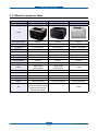
2.1.2.5 Consumables
Item
Image
Pages Printed
Part number
Black Toner
cartridge
Approx. Initial : 1,000 Pages* CLT-K407S,
Sales : 1,500 Pages*
CLT-K4072S (Black)
Color Toner
cartridge
Approx. Initial : 700 Pages*
Sales : 1,000 Pages*
CLT-C407S,
CLT-C4072S (Cyan)
CLT-M407S,
CLT-M4072S (Magenta)
CLT-Y407S,
CLT-Y4072S (Yellow)
Imagine unit
Approx. 24000 images*
CLT-R407
Waste Toner
Approx. 10,000 images
CLT-W409
Pick-up roller
Approx. 50,000 pages
JC97-03028A
Fuser unit
Approx. 50,000 pages(B&W)
/ 12,500 pages (Color)
JC91-00978A (220V)
JC91-00997A (110V)
T2 roller
Approx. 50,000 pages(B&W)
/ 12,500 pages (Color)
JC95-01197A
ITB
Approx. 50,000 pages(B&W)
/ 12,500 pages (Color)
JC96-05874A
Remark
CRU
FRU
* Average A4-/letter-sized page count based on Std. ISO 19798 of individual colors on each page.
Usage conditions and print patterns may cause results to vary.
Service Manual
2-7
Samsung Electronics
Product spec and feature
2.1.2.6 Reliability & Service
Item
CLP-320/325
CLP-320N/CLP-325W
Max Monthly Duty
20,000 image
(Color: 16,000/ Mono: 4,000)
20,000 image
(Color: 16,000/ Mono: 4,000)
SET Life Cycle
100,000image or 5 years
whichever comes first
100,000image or 5 years
whichever comes first
MTBF
40,000 images
(color 32,000 images and black
8,000 images : total 40,000
image)
40,000 images
(color 32,000 images and black
8,000 images : total 40,000 image)
MTTR
<30 min.
<30 min.
Real-time Clock
No
No
System record
Total image count
Total page count (color/mono)
Imaging unit Information
Transfer roller life
Transfer belt life
Toner information
Tray roller life
Total image count
Total page count (color/mono)
Imaging unit Information
Transfer roller life
Transfer belt life
Toner information
Tray roller life
Minimum System Requirement
Pentium-Ⅱ 400MHZ, 64MB RAM, Pentium-Ⅱ 400MHZ, 64MB RAM,
300MB HDD, Internet Explorer 5.0 300MB HDD, Internet Explorer 5.0
Service Manual
2-8
Samsung Electronics
Product spec and feature
2.1.2.7 Environment
Item
CLP-320/325
CLP-320N/CLP-325W
Ready
Less than 160W
Less than 160W
Average
Less than 350W
(Currency:5A(110V)/3A(220V)
Less than 350W
(Currency:5A(110V)/3A(220V)
Max/Peak
700W/1KW
700W/1KW
Sleep/Power off
Less than 5W/0.45W
Less than 8W/0.45W (325W)
Less than 6W (320N)
Input Voltage
AC 110V~127V, AC 220V~240V
AC 120V/AC 220V(EXP version)
AC 110V~127V, AC 220V~240V
AC 120V/AC 220V(EXP version)
Input Frequency
50 / 60Hz(+/- 3Hz)
50 / 60Hz(+/- 3Hz)
Printing
Mono : 46dBA
Color : 48dBA
Mono : 46dBA
Color : 48dBA
Standby
Background noise level
Background noise level
Sleep
Background noise level
Background noise level
Warm Up Time
From Cold Status
(At rated volt)
Less than 35 seconds
Less than 35 seconds
Temperature
Operating
10~32.5℃
10~32.5℃
Power
Consumption
Power Supply
Noise
Humidity
Storage (Un-Packed) 5~35℃
5~35℃
Storage (Packed)
-20~50℃
-20~50℃
Operating
20 ~ 80% RH
20 ~ 80% RH
Storage (Un-Packed) 20 ~ 80% RH
20 ~ 80% RH
Storage (Packed)
10~90% RH
10~90% RH
Normal: 0~3000ft (0~1000m)
Normal: 0~3000ft (0~1000m)
High: 3001~6600ft( ~2000m)
High: 3001~6600ft( ~2000m)
Higher: 6601~9900ft( ~3000m)
Higher: 6601~9900ft( ~3000m)
Highest;9901~13000ft( ~4000m)
Highest;9901~13000ft( ~4000m)
Altitude
2.1.2.8 Accessory
Item
CLP-320/325
CLP-320N/CLP-325W
Quick setup guide
Yes
Yes
Owner’s manual
Yes
Yes
S/W CD ROM
1 : for Driver
1 : for Driver
2 : for Network
S/W
1 CD for Driver, SmarThru 4 1 CD for Driver, SmartThru 4, EUG 1 CD for Driver, SmartThru 4, EUG
Toner Cartridge
4 EA (0.7K/0.5K yield ISO 19752
5% Coverage)
4 EA (0.7K/0.5K yield ISO 19752
5% Coverage)
Power Cable
1 EA
1 EA
Printer Cable
1 EA
1 EA
Service Manual
2-9
Samsung Electronics
Product spec and feature
2.1.3 Model Comparison Table
Samsung
Samsung
HP
CLP-325/325W
CLP-315/315W
CP-1215
Print speed (M/C)
16/4ppm
16/4ppm
12/8ppm
FPOT
14/26 sec
14/26 sec
24/30 sec
Resolution
Up to 2400 dpi
Up to 2400 dpi
2400 HP ImageREt
CPU
375 MHz
375 MHz
264 MHz
Std Memory
32 MB (256 MB)
32 MB
16 MB (16MB)
Emulation
PCL6(325W), SPL-C
SPL-C
GDI
Duplex
Manual
Manual
Manual
Paper Handling
130 CST
150 CST
150 CST
Output
80 sheet
80 sheet
125
Noise
45dB/ 47dB
(Color/Black)
45dB/ 47dB
(Color/Black)
47dB
Max. Monthly Duty
20,000
20,000
25,000
Size
388 x 313 x 243
388 x 314 x 237
398.7 x 452 x 253
Weight
11kg (TBD)
11kg
17.6 kg
Image
Interface
USB 2.0, Wireless(325W) USB 2.0, Wireless(315W)
Toner
1.5K/1K (1K/0.7K)
Etc
1W Soft Power
Print Screen Button (325)
DLNA Printing (325W)
WPS Button (325W)
Service Manual
1.5K/1K (1K/0.7K)
USB 2.0
2.2K/1.4K(0.75K)
9 LED
2-10
Samsung Electronics
Product spec and feature
2.2 System Overview
This chapter describes the functions and operating principles of the main components.
2.2.1 System Structure
The Printer function consists of the Engine part and the Main Controller part, and the Engine part consists
of the Mechanical part comprising a Frame, Feeding, Developing, Driving, Transferring, Fusing, and Cabinet
and the Electrical part comprising a SMPS, a HVPS, a LSU, and some facilities in the Main Controller to
control the Engine part for printing.
2.2.1.1 Main Parts of System
Stacking Area
Fuser
T1 Roller
DEVE Y
ITB
DEVE M
OPC
T2 Roller
Regi.
Roller
DEVE C
DEVE K
Waste
Tank
LSU
Pick up
Roller
Cassette
Service Manual
2-11
Samsung Electronics
Product spec and feature
① Cassette
• Feeding Method : Cassette Type
• Feeding Standard : Center Loading
• Feeding Capacity : Cassette 150 Sheets(75g/㎡, 20lb Pa per Standard)
• No Manual Feeder
• Paper Detecting Sensor : Photo Sensor (Empty, Registration, Exit)
• Paper Size Sensor : None
② LSU(Laser Scan Unit)
The LSU unit is controlled by video controller. It scans the video data received from video controller with
laser beam by using the rotation principle of the polygon mirror to create the latent image on the OPC
drum. It is the core part of LBP.
The OPC drum rotates as the same speed as the paper feeding speed. It creates the /HSYNC signal and
sends it to the engine when the laser beam of the LSU reaches the end of the polygon mirror, and the
engine detects the /HSYNC signal to arrange the vertical line of the image on the paper. After detecting
the /HSYNC signal, the image data is sent to the LSU to arrange the its margin on the paper.
• Consisted of LD(Laser Diode) and Polygon Motor Control.
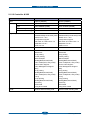
Error
Phenomenon
Polygon Motor Error
The Rotation of Polygon Motor can not reach stable
Hsync Error
hough the rotation of Polygon Motor reach stable, the signal of Hsync is
T
not occurred
Service Manual
2-12
Samsung Electronics
Product spec and feature
③ 2nd Transfer Ass’y
• The life span: Print over 100,000 sheets (in 15~30 )
• Specification: Similar to CLP-300 Series
④ Fuser Ass’y
This unit consists of Heat Roller, a Thermostat and a Thermistor. It melts and fuses the toner, transferred
by the transfer roller onto the paper, by applying pressure and high temperature to complete printing job.
* Heat Lamp : Kunckle Type
* Fusing system : 3-Roll Fusing type
- Heat roller : Pipe type (Lamp inside)
- Pressure roller
- Pressure roller Shaft
* Thermistor - Temperature-Measuring Device
* Thermostat - Critical Temperature-Detecting Device
* The life span – 100k(black)/color(25k)
Thermostat
When a heat lamp is overheated, a Thermostat cuts off the main power to prevent over-heating.
- Non-Cotact type Thermostat
Heat roller
The heat roller transfers the heat from the lamp to apply a heat on the paper. The surface of a heat
roller is coated with Teflon, so toner does not stick to the surface.
Pressure roller
A pressure roller mounted under a heat roller is made of a silicon resin, and the surface also is coated
with Teflon. When a paper passes between a heat roller and a pressure roller, toner adheres to the surface
of a paper permanently.
Service Manual
2-13
Samsung Electronics
Product spec and feature
⑤ & ⑥ ITB(Intermediate Transfer Belt) & 1st Transfer Roller
• The life span: Print over Approx. 50,000 pages(B&W) / 12,500 pages (Color)
• The ITB unit includes 1st Transfer Roller
⑦ & ⑧ OPC(Organic Photo-Conductor) & Developer
• The life span: Print over 50,000 Images (Both)
• Imagine Unit consists of 4 kinds of Developer , OPC, and Deve. Main Frame
⑨ Toner Kits
• The life span: Color -> 1000 images (Std. ISO 19798 Print-Out)
Black -> 1500 images (Std. ISO 19798 Print-Out)
⑩ Driver Ass’y
• It is a power delivery unit by gearing
• By driving the motor, it supplies the power to the feeding unit, the fusing unit, and the distributing unit.
• The Main Motor is similar to CLP-310 Series Main Motor.
⑪ Wireless PBA (Only CLP-325W)
• CLP-325W model has a Wireless PBA to use wireless network.
Service Manual
2-14
Samsung Electronics
Product spec and feature
2.2.1.2 EP Process
- Structure of EP Process
P1: Image
on OPC
Blade
ITB Unit
P2: Image
on Media
Media Path
OPC
~
Blade
Developer
Eraser
Charger
Laser Scanning Unit
Service Manual
2-15
Samsung Electronics
Product spec and feature
① Charging
• Conductive Roller charging
• Applied voltage : -1.1kV
• Charge acceptance : -520V
• OPC coating thickness : 21um
• OPC diameter : Φ60mm
• Eraser system
1. Organic Photoconductor is charged to uniform voltage by conductive roll charging method
2. No ozone is produced because corona is not used
3. Charger roll is cleaned with cleaning roll
4. Toner remained on OPC after T1 process is cleaned by cleaning blade and retrieved into waste toner box
by auger and belt driving mechanism
② Exposing
• One polygon motor ( 6 facet )
• Single beam LD (1ea)
• LD wavelength : 785nm
• Polygon motor rpm : 29685
• LSU energy : 0.25uJ/cm^2
• OPC exposed potential : -50V
1. Exposing is implemented by laser striking on to OPC with uniform potential
2. Laser beam is modulated according to image to be printed that is from PC
3. Latent Image is formed on OPC, which is developed with toner
③ Developing
• Non-magnetic, mono component
• Non-contact development
• Developing bias : DC + AC
• AC peak to peak : 1.5 ~ 2.0kV
• Roller diameter : Φ10mm
• Process speed ratio : 1.2 (OPC=1.0)
• Color order : Y -> M -> C -> K
1. Only latent image formed by exposing process is developed with toner
2. AC + DC Voltage is being used to develop toner into latent image on OPC because non-contact
developing method is adopted
3. Y, M, C, and K Images are sequentially developed onto OPC and transferred onto Intermediate Transfer
Belt (hereafter ITB) to form a color image on ITB
4. Toner Bottles are used to supply toner into developer compartment
5. Toner level is being sensed to control toner supply from toner bottle to developer
Service Manual
2-16
Samsung Electronics
Product spec and feature
④ Transfer 1
• Multi-pass transfer
• Indirect transfer
• Transfer voltage : 0.5 ~ 2.0kV (controllable)
• Roller diameter : Φ14mm
• Transfer unit life : 100K images
1. Developed Image on OPC is transferred onto ITB by T1 Process
2. T1 Voltage is positive which attract toner to ITB
3. 4 times of T1 process is required to make a color image on ITB, which means multi-pass process
4. ITB has a hole as a fiducial mark for timing. Engine control for color image is synchronous with it, ITB
Home Sensing Signal
⑤ Transfer 2
• Indirect transfer
• Transfer voltage : 1 ~ 4.0kV (controllable)
• Roller diameter : Φ18.6mm
• Transfer unit life : 100 K images
1. Color image formed on ITB is transferred onto media by T2 process
2. T2 voltage is also positive to get color image moved onto media
3. Toner remained on ITB after T2 process is cleaning by ITB cleaning blade and collected and
4. Transported and retrieved into waste toner box by auger and belt driving system
5. T2 Roll is engaged when color image is being transferred onto media. Otherwise it is disengaged. Clutch
is used for driving T2 Roll engagement and disengagement
⑥ Fusing
• 3 Roll system
-> short warm-up time (35sec)
• Post Pressure Roll
1. Color Image on media is melted down and fixed into media by fusing process
Service Manual
2-17
Samsung Electronics
Product spec and feature
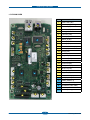
2.2.2 Main PBA Description
2.2.2.1 Main Controller PBA
- CLP-320/325
NO.
19
1
Deve home CON.(3P)
2
ITB CLT(3P)
3
Deve CLT(2P)
4
4
Debug(4P)
5
T2 CLT(3P)
16
7
BLDC I/F(10P)
8
JTAG (8P)
9
Regi CLT.(2P)
10
Fuser CLT(2P)
12
Fuser(2P)
13
SMPS_P(4P)
14
OPE & ITB (18P)
15
HVPS(26P)
16
LSU Con.(16P)
17
Empty Sensor (3P)
18
Key PTL(4P)
19
Cover OPEN (2P)
20
USB (4P)
21
Pickup CLT. (3P)
22
S-CRUM I/F (5P)
23
SMPS_S (6P)
A
CPU(Jupiter5)
B
DDR2 (32MB)
C
Serial FLASH(2MB)
D
EEPROM
9
10
D
5
8
A
6
20
C
17
7
B
22
3
13
23
1
2
15
14
Service Manual
NAME
11
18
2-18
Samsung Electronics
Product spec and feature
- CLP-320N/325W
NO.
NAME
1
OPE & ITB (18P)
3
W-LAN (6P) (W Only)
4
Ethernet (8P)
5
S-CRUM I/F (5P)
24
6
Debug(4P)
7
LSU Con.(16P)
10
8
JTAG (8P)
9
SMPS_S (6P)
10
Fuser(2P)
11
SMPS_P(4P)
12
Deve home CON.(3P)
15
USB (4P)
16
Empty (3P)
18
T2 CLT(3P)
19
Regi CLT.(2P)
20
Deve CLT(2P)
22
ITB CLT(3P)
24
Fuser CLT(2P)
26
Pickup CLT. (3P)
27
BLDC I/F(10P)
28
HVPS(26P)
29
Key PTL(4P)
30
Cover OPEN (2P)
A
CPU(Jupiter5)
B
DDR2 (64MB X 2)
C
Nor FLASH(32MB)
D
EEPROM (Under PBA)
E
PHY Chip
F
USB IC(W Only)
15
4
E
18
27
3
F
16
19
D
26
A
29
8
5
B
B
6
20
12
22
9
1
7
28
Service Manual
11
30
2-19
Samsung Electronics
Product spec and feature
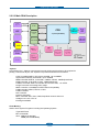
2.2.2.3 Main PBA Description
FLASH
CPU
EEPROM
Jupiter5(360MHz)
24C64
DDR2 SDRAM
Jupiter5
A Proprietary SoC, Jupiter5, executes and controls all jobs and functions to be required for
printing. To do these all jobs, the Jupiter5 incorporates all H/W blocks as follows.
▪ CPU Core ARM 926ESJ, I/D-Cache 16/16KB , Up to 400MHz
▪ System Bus Internally 32-bit width, Up to 120MHz
▪ MEM Controller DDR1/2, 16-bit width, 166MHz, 4-Bank, 128MB Space/bank
▪ ROM Controller 16-bit width, 4-bank, 16MB Space/bank
▪ CODEC Controller JBIG 4-ch Decoder and 2-ch Encoder, 1-ch JPEG
▪ Image Processor Processing Scan Image
▪ MAC Controller 10/100Mbps Full IEEE 802.3 Compatibility
▪ USB Controller USB2.0, Device or Host
▪ UART Controller
▪ I2C Controller
▪ Interrupt Controller
▪ Misc. Controller ADC, DAC, PWM, Step Motor Control and so on
▪ Voltage Core 1.0V, I/O 3.3V
▪ Package 416PBGA
Flash Memory
Used to store System Programs including the Operating System.
▪ Type NOR Flash
▪ Bus 16-bit width
▪ Size : 2
MB (CLP-320/325)
32MB (CLP-320N/325W)
Service Manual
2-20
Samsung Electronics
Product spec and feature
System Memory
Used as a Printing buffer for printing, a Scan buffer for scanning, a ECM Buffer for System
Working Area.
▪ Type DDR2 SDRAM
▪ Bus 16-bit 166MHz
▪ Size 32MB (320/325) / 256MB(320N/325W)
CRU Control
Used to store the printing and operating information into a Security EEPROM in 4 CRUs, Y,M,C
and K Imaging Cartridge, respectively by the CHORUS3.
▪ Access I2C Bus Ch.2 400KHz
▪ Security Size 2K-bit
System Information Control
Used to store the system operating information needed at printing into a EEPROM in the Main Controller by
the CHORUS3.
▪ Access I2C Bus Ch.1 400KHz
▪ EEPROM Size 64Kbit
OPE Interface
Used to control the OPE by the CHORUS3. Through CHORUS3’s GPIO pins, all LEDs and Keys in the OPE
are controlled.
I/O Port
Used to receive or transmit some data from/to the Host.
▪ USB Device USB2.0 High speed 480Mbps
▪ Network Ethernet 10/100-Base Tx
(note) The Network only equipped at CLP-320N/325N, not CLP-320/325.
Engine Control
Used to control all parts to be required at printing by the CHORUS 3.
▪ Sensors Paper Empty
Paper Registration
Waste Toner Bottle
Paper Exit
Temperature sensors
Etc.
▪ Clutches(Solenoid) Paper Pick Up
Paper Registration
Etc.
▪ Motor 1 BLDC
▪ LSU
▪ Fuser Control the Fuser’s temperature
▪ HVPS Control the high voltage outputs
▪ ADC Reading the Fuser’s temperature and the high voltage outputs’ feedback
▪ Cover Open Sensing
Service Manual
2-21
Samsung Electronics
Product spec and feature
2.2.2.4 SMPS(Switching Mode Power Supply) PBA
SMPS is the power source of the entire system. It is assembled by an independent module, so it is possible
to use for common use. It is mounted at the side of the set. It is consisted of the SMPS part which supplies
the DC Power for driving the system and the AC Heater control part which supplies the AC Power to the
Fuser. The SMPS has two DC output channels, +5V and +24V.
Fuse
SMPS
Power
AC
input
SMPS
Signal
Fuser
AC Input
Input Rated Voltage
AC 110V~127V, AC 220V~240V
AC 120V/AC 220V(EXP version)
Input fluctuating range
AC 99V~135V, AC 198V~264V
Rated Frequency
50/60 Hz
Frequency Fluctuating
47~63 Hz
Input Current
< 4.0Arms, 2.0Arms
Rated Output Power
No
Item
CH1
CH2
1
Channel Name
+5V
+24.0V
2
Connector Pin
CON 3
5V Pin: 1
GND Pin: 2
CON 3
24V Pin: 3
GND Pin: 4
3
Rated Output
+5V ±5%
(4.75~5.25V)
+24V ±10%
(21.6~26.4V)
4
Max. Output Current
2A
2.5 A
5
Peak Loading Current
2.2 A
2.7 A
6
Ripple Noise
<100mVp-p
<500mVp-p
7
Maximum Output
10.2W
60W
8
Peak Output
11W
64.8W
9
Protection for loading shortage and
overflowing current
Shut down or Fuse
Protection
Shut down or Output
Voltage Drop
Service Manual
2-22
Remark
1ms
1ms
Samsung Electronics
Product spec and feature
2.2.2.5 HVPS(High Voltage Power Supply) PBA
The HVPS creates the high voltages for T1(+), T2(+,-), Charger(-), DEV, and SUPPLY and then, supplies
these voltages to the Developer part for making best condition to print. The HVPS part takes the 24V and
outputs the high voltages and then, the high voltages are supplied to the Toner, OPC Cartridge, and Transfer
Belt and Roller.
FAN
WASTE
BIAS AC
+141V 3%
BIAS DC
-295V 3%
SUPPLY DC
-595V 3%
Exit Sensor
T1
+1000V 3%
T2
-1300V 15%
Charger
-1000V 3%
Main
PBA
Regi
Service Manual
2-23
Samsung Electronics
Product spec and feature
1) Charger Voltage : Charger
• Function: voltage that charges OPC surface up to -500V~ -800V.
• Output voltage: -1.0KV ~ -2.0KV DC 3%
•E
rror type: if the voltage fails to be output to Charger Roll, OPC surface will not be charged, and the
toner on the developer roller will be transferred to OPC Drum, printing black paper.
2) 1st Transfer High Voltage : T1(+)
• Function: voltage necessary for transferring toner developed on OPC Drum surface onto ITB.
• Output voltage: Max +2.0KV 3%(Duty variable, no load)
•E
RROR type: if T1(+) output fails, the toner on OPC drum will not be transferred to ITB normally and the
image will be blurred.
3) 2nd Transfer High Voltage : T2(+)
• Function: voltage used to transfer the toner primarily transferred on ITB again onto paper.
• Output voltage: Max +5.0KV 3%(Duty variable, no load)
•E
RROR type: if T2(+) output fails, the toner on ITB will not be transferred to paper normally and the
image will be blurred.
4) T2 Cleaning Voltage : Clean : T2(-)
•F
unction: prevent reverse side of paper from being dirtied, by recovering the negatively charged toner
remaining at Transfer Roller and sending it onto ITB.
•O
utput voltage: with no feedback control, output fixed voltage(-1300V 15%)
• ERROR type: reverse side of paper will be dirtied.
5) Supplying Voltage : Supply AC+DC(-)
•F
unction: voltage that makes toner to develop on the area exposed by LSU by means of potential
difference, output will be the voltage of AC+DC overlapped form.
• Output voltage: AC 600V ~ 2000V p-p 1.5%
DC -50V ~ -600V DC 3%
• ERROR type: 1
. if supply is GND, density will be extremely low.
2. if supply is floating (for insecure terminal contact), density will be down so slightly that it
is impossible to make out with naked eyes.
6) Developing Voltage : Deve AC+DC(-)
• Function: voltage that supplies toner to Developing Roller
• Output voltage: AC 250V ~ 1650Vp-p 1.5% (supply voltage is connected to ZENER Diode 350V)
DC -50V ~ -600V DC 3%
• ERROR type: 1
. if Deve is GND, density will be extremely down.
2. if Deve is floating (for insecure terminal contact), density will be extremely down.
Service Manual
2-24
Samsung Electronics
Product spec and feature
2.2.3 CRUM
The CLP-320N engine will be equipped with electronics that can read and write data into NVRAMs otherwise
known as CRUMs that reside within 1) C, M, Y, K Toner cartridges.
The CRUM has a company ID, and electronics logo.
The toner CRUM also identifies the type of toner cartridge (Standard or High Capacity). The CRUMs contain
fixed data such as the low warning point, specified life point, and hard stop point (on toner)
and also store the current life count (pages count, pixels count, images count) and % of usage (gas gauge)
data.
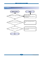
■ In the case of Refill Toner Install
1) Perception of Refill Cartridge (when power is on or the cover is closed)
End of Life / life span data initialization -> judge to be Refill Cartridge
End of Life / life exhausted (simple refill) -> stop printing caused by life exhaustion
2) Operating
It is impossible to control appropriate development parameters, for there s no toner specification data.
It runs with the setting of default development parameter. (Image quality will be degraded, for the lack of
appropriate respond to the change of time and environment.)
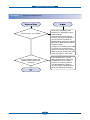
■ Process after CRU life expiration
1) Record the information of End of Life.
2) Clear some information of Operation Area.
-> Supplier/Model Name/MFC date/Serial Number (Manufacture Information)
-> Let cartridge refiller initialize manufacture information and life span information.
Service Manual
2-25
Samsung Electronics
Product spec and feature
2.3 S/W Structure and Descriptions
2.3.1 Architecture
The belt CRUM interface board is a transmission belt CRUM interface board of the photoelectric Dry Color
Laser Printer, mounted on the printer body, making it possible to physically combine the body and the belt
CRUM board.
Printer Driver
Language Monitor
Status Monitor
Network Card F/W
Printer F/W
2.3.2 Language Monitor
Language Monitor is a part of the Printer Driver and the Windows Spool System. The main roll of the
Language Monitor is that sends a job start message to the Status Monitor. Therefore the Status Monitor
can start polling to get the printer status.
The second roll is that sends the job information such as User ID and Job ID to the Status Monitor and the
Printer F/W. Hence the Status Monitor can stop polling because the Printer F/W informs the Status Monitor
that printing job is complete.
2.3.3 Status Monitor
Status Monitor has no user interface. It shows only HTML help when any error occurs during printing jobs.
Service Manual
2-26
Samsung Electronics
Product spec and feature
2.3.4 Network Interface
Printer Driver
Printer Driver
User ID + Job ID
+
Language
Monitor
Printer Data
Printer Data
Printer Server
(Kernel / NPC)
Printer Name
Port Name
User ID
Printer Data
Job ID Language
Printer Server IP Addr
Monitor
User ID + Job ID
+
Printer Data
SNMP
Printer Server
(Kernel / NPC)
Job ID
Request Printer Status
Printer Server
(Kernel / NPC)
Printer Name
Status
Port Name
User ID
Job ID
Printer Server IP Addr
Printer Status
Monitor
Request Job Status
Job Table
SNMP
Printer Server
(Kernel / NPC)
Job ID
Request Printer Status
Status Monitor Data FlowPrinter Status
Status Monitor
Request Job Status
Job Table
After polling is started, Status Monitor has to know when it stops the polling. For this reason, the Network
Printer Server should inform of completing job when the printing job is finished.
When Status Monitor requests a job status, the Printer Server returns the job table that contains user id, job
id, and job status (printing or complete or
canceled).
Status
Monitor Data Flow
2.3.5 Printer Driver <-> Status Monitor
Set option value
The Printer Driver and the Status Monitor can set/get some data to the
system registry to share the Status
enable/disable
or
Monitor information such as the polling interval.
polling interval
Set last error status
When the user wants to set the option of the Status Monitor manually, he or she can set it using the Printer
System
Driver User
Interface.
the Status Monitor is disabled, the Printer
Status Monitor
Status
MonitorSo, if the user set option that
Driver can’s
Registry
show HTML Help to the userGet
although
the
error
has
occurred
while
printing.
option value
Get last error status
enable/disable
or
polling interval
Set last error status
Status Monitor
SharingSystem
Registry Info
Registry
Get option value
enable/disable
or
polling interval
Set option value
enable/disable
or
polling interval
Printer Driver
Get last error status
Sharing Registry Info
Service Manual
2-27
Samsung Electronics
Product spec and feature
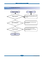
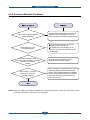
2.3.6 System F/W Flow
Process
Output
Photo Sensor ( intensity
of radiation )
PWM
LED
LED PWM Output
density
Density pattern
printing
PWM
LED PWM decision
Comparator Threshold
voltage PWM decision
Comparator
Color Registration measure
LSU
Auto Color Registration
pattern printing
Color Registration adjustment
Page Sync. modify
Line Sync. modify
LSU
temperat
ure
sensor
Service Manual
Video Clock Freq.
modify
ADC
Video data
P Sync.
L Sync.
clock
Video signal
generator
LSU temperature control
2-28
Samsung Electronics
Product spec and feature
2.3.7 CRUM Overview
- Stands for “Customer Replaceable Unit Monitor”
- EEPROM, SAMSUNG CRUM is used for CRUM Memory.
- CRUM stores various information on consumables (including consumables’ life).
- In CLP-32x Series, total four CRUM’s are used
(four on toner cartridges)
CRUM stores the following information
• Model Name
• Supplier ID
• Serial Number
• Company ID
• MFG Date
• Capacity
• Page Count
- Toner Cartridge and Transfer Belt
- Indicates how many pages are printed by using the consumable
• Dot Count
- Toner Cartridge Only
- Indicates how many dots are printed by using the toner cartridge
• Image Count
• Model ID
Service Manual
2-29
Samsung Electronics
Product spec and feature
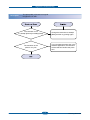
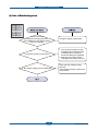
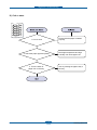
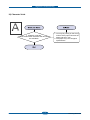
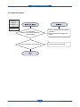
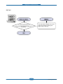
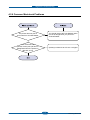
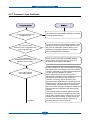
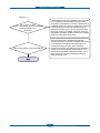
2.3.8 Initailize Flow
Service Manual
2-30
Samsung Electronics
Product spec and feature
Service Manual
2-31
Samsung Electronics
Disassembly and Reassembly
3. Disassembly and Reassembly
3.1 Precautions when replacing parts
3.1.1 Precautions when assembling and disassembling
* Use only approved Samsung spare parts. Ensure that part number, product name, any voltage, current or
temperature rating are correct. Failure to do so could result in damage to the machine, circuit overload, fire
or electric shock.
* Do not make any unauthorized changes or additions to the printer, these could cause the printer to
malfunction and create electric shock or fire hazards.
* Take care when dismantling the unit to note where each screw goes. There are 19 different screws. Use of
the wrong screw could lead to system failure, short circuit or electric shock.
* Do not disassemble the LSU unit. Once it is disassembled dust is admitted to the mirror chamber and will
seriously degrade print quality. There are no serviceable parts inside.
* Regularly check the condition of the power cord, plug and socket. Bad contacts could lead to overheating
and firfe. Damaged cables could lead to electric shock or unit malfunction.
3.1.2 Preautions when handling PBA
Static electricity can damage a PBA, always used approved anti-static precautions when handling or storing
a PBA.
>> Precautions when moving and storing PBA
1. Please keep PBA in a conductive case, anti-static bag, or wrapped in aluminum foil.
2. Do not store a PBA where it is exposed to direct sunlight.
>> Precautions when replacing PBA
1. Disconnect power connectors first, before disconnecting other cables
2. Do not touch any soldered connections, connector terminals or other electronic parts when handling
insulated parts.
>> Precautions when checking PBA
1. Before touching a PBA, please touch other grounded areas of the chassis to discharge any static electrical
charge on the body.
2. Take care not to touch the PBA with your bare hands or metal objects as you could create a short circuit
or get an electric shock. Take extra care when handling PBAs with moving parts fitted such as sensors,
motors or lamps as they may get hot.
3. Take care when fitting, or removing, screws. Look out for hidden screws. Always ensure that the correct
screw is used and always ensure that when toothed washers are removed they are refitted in their original
positions.
3.1.3 Releasing Plastic Latches
Many of the parts are held in place with plastic latches.
The latches could easily break if forced; release them carefully.
To remove such parts, press the hook end of the latch away from the part to
unlatch.
Service Manual
3-1
Samsung Electronics
Disassembly and Reassembly
3.2 Parts for Maintenance and Repair
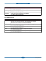
3.2.1 Replacement interval for parts with a limited life
Some of the parts in this printer have a limited life, shorter than that of the whole machine. These parts must
be replaced periodically.
The table below shows the interval at which these parts should be replaced.
The table shows the life of each part, and is measured when using A4 paper. When servicing a machine
always check the status of these parts using the control panel and ensure that parts are replaced at the
appropriate times otherwise a general degradation in print quality will occur.
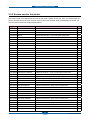
Item
Pages Printed
Part number
Remark
Black Toner cartridge
Approx. Initial : 1,000 Pages*
Sales : 1,500 Pages*
CLT-K407S, CLT-K4072S (Black)
Color Toner cartridge
Approx. Initial : 700 Pages*
Sales : 1,000 Pages*
CLT-C407S, CLT-C4072S (Cyan)
CLT-M407S, CLT-M4072S (Magenta)
CLT-Y407S, CLT-Y4072S (Yellow)
Imagine unit
Approx. 24000 images*
CLT-R407
Waste Toner
Approx. 10,000 images
CLT-W409
Pick-up roller
Approx. 50,000 pages
JC97-03028A
Fuser unit
Approx. 50,000 pages(B&W) /
12,500 pages (Color)
JC91-00978A (220V)
JC91-00997A (110V)
T2 roller
Approx. 50,000 pages(B&W) /
12,500 pages (Color)
JC95-01197A
ITB
Approx. 50,000 pages(B&W) /
12,500 pages (Color)
JC96-05874A
CRU
FRU
* Average A4-/letter-sized page count based on Std. 19752 of individual colors on each page. Usage conditions and print
patterns may cause results to vary.
** Image counts based on one color on each page. If you print documents in full color (Cyan, Magenta, Yellow, Black),
the life of this item will be reduced by 25%.
Service Manual
3-2
Samsung Electronics
Disassembly and Reassembly
3.2.2 Printer Cleaning
A printer should be regularly cleaned, especially if it is used in a dusty environment. This will ensure that print
quality remains high and failure due to contamination of printing services is less likely to occur.
* Clean the printer with a soft, lint free, cloth dipped in a “Recommended cleaner” “Recommended cleaner”
can be purchased from our service center. (where available)
* Do not touch the transfer roller when cleaning the inside of the printer. Grease and oils from the skin will
contaminate the surface and reduce print quality.
* Do not touch transfer roller when cleaning inside of machine. If transfer roller gets dirty, printing quality
could be low.
* Please refer to the User Manual for cleaning instructions.
Service Manual
3-3
Samsung Electronics
Disassembly and Reassembly
3.3 Information Related to Disassembly and Assembly.
3.3.1 Special service parts
Never disassemble or adjust the items mentioned, a stock of these items should be maintained.
1) Disassembly of the LSU unit
4) Disassembly of DEVE drive ass’y and
the main drive ass’y
There are no serviceable parts inside the LSU.
Alignment of the mirrors is critical.
Opening the LSU will allow dust into the laser
and significantly reduce print quality.
It is very dangerous to operate or service a
machine with the LSU open or system interlocks
disabled. Exposure to laser radiation can cause
blindness.
The alignment of the drive mechanism is critical
and it has been set up in factory using a jig
and a driving gear. It is adjusted for the best
gearing alignment. If the motor is disassembled
alignment would not be maintained and
this could cause operational noise and
image problems: image alignment and toner
distribution may be affected.
2) Disassembly of the ITB unit
5) Disassembly of terminal parts
Do not disassemble the ITB. The alignment of
the home sensor is critical and is set up in the
factory on a special jig.
Incorrect re-assembly will cause print quality
degradation.
Do not adjust the variable resistors on the PBA.
They have been already adjusted in the factory.
6) Disassembly of the fuser unit
3) Care of the Toner cartridge
Toner cartridges contain an extremely fine
powder. Please keep toner cartridges away from
children. The toner powder contained in the
toner cartridge may be harmful and if swallowed
you should contact a doctor. Take care not to
spill toner - spillages should be cleaned with
a vacume cleaner and washed in cold water
(hot water sets the toner). Do not touch the
developer roller surface as contamination will
reduce print quality. Take care not to damage
the roller’s surface when installing or removing
a toner cartridge.
Service Manual
3-4
- The fuser melts toner onto the paper at a
high temperature: therefore, you need to take
special care not to get burned by a hot fuser.
When removing the fuser from a set that has
recently been operating you need to take extra
care.
- Do not touch an AC line (Copper contact) on a
main frame even after removing the fuser.
Samsung Electronics
Disassembly and Reassembly
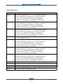
3.3.2 Screws used in the printer
The screws listed in the table below are used in this printer. Please ensure that, when you disassemble the
printer, you keep a note of which screw is used for which part and that, when reassembling the printer, the
correct screws are used in the appropriate places.
Sec_Code
Location
Description
Qty
6003-000196 FUSER
SCREW-TAPTYPE;PWH,+,B,M3,L10,NI PLT,SWRCH18A
7
6003-000282 FUSER
SCREW-TAPTYPE;BH,+,-,B,M3,L8,ZPC(BLK),SWRCH18A,-
3
6001-000130 DRIVE
SCREW-MACHINE;BH,+,M3,L6,ZPC(WHT),SWRCH18A
1
6002-000440 DRIVE
SCREW-TAPPING;PWH,+,2,M3,L8,ZPC(BLK),SWRCH18A
24
6003-000301 DRIVE
SCREW-TAPTYPE;BH,+,S,M4,L6,ZPC(WHT),SWRCH18A
1
6003-000152 FRAME MAIN
SCREW-TAPTYPE;PH,+,-,B,M2,L10,ZPC(WHT),SWRCH18A,-
2
6003-000196 EXIT
SCREW-TAPTYPE;PWH,+,B,M3,L10,NI PLT,SWRCH18A
2
6003-000196 FRAME
SCREW-TAPTYPE;PWH,+,B,M3,L10,NI PLT,SWRCH18A
15
6003-000196 GUIDE PICKUP
SCREW-TAPTYPE;PWH,+,B,M3,L10,NI PLT,SWRCH18A
4
6003-000196 GUIDE-RAIL
SCREW-TAPTYPE;PWH,+,B,M3,L10,NI PLT,SWRCH18A
4
6003-000196 PBA-OPE(T)
SCREW-TAPTYPE;PWH,+,B,M3,L10,NI PLT,SWRCH18A
1
6003-000269 FRAME MAIN
SCREW-TAPTYPE;BH,+,-,S,M3,L6,ZPC(WHT),SWRCH18A,-
1
6003-000301 FRAME MAIN
SCREW-TAPTYPE;BH,+,S,M4,L6,ZPC(WHT),SWRCH18A
1
6003-000196 COVER-FRONT
SCREW-TAPTYPE;PWH,+,B,M3,L10,NI PLT,SWRCH18A
4
6002-000440 COVER-REAR
SCREW-TAPPING;PWH,+,2,M3,L8,ZPC(BLK),SWRCH18A
1
6003-000196 COVER-TOP
SCREW-TAPTYPE;PWH,+,B,M3,L10,NI PLT,SWRCH18A
2
6003-000261 COVER-TOP
SCREW-TAPTYPE;BH,+,-,B,M3,L6,ZPC(WHT),SWRCH18A,-
1
6003-000282 LSU
SCREW-TAPTYPE;BH,+,-,B,M3,L8,ZPC(BLK),SWRCH18A,-
10
6003-000282 ELA UNIT-LSU LD
SCREW-TAPTYPE;BH,+,-,B,M3,L8,ZPC(BLK),SWRCH18A,-
2
6002-000308 CARTRIDGE TONER Y
SCREW-TAPTYPE;PH,+,-,B,M2.6,L6,ZPC(WHT),SWRCH18A,-
8
6002-000308 CARTRIDGE TONER M
SCREW-TAPTYPE;PH,+,-,B,M2.6,L6,ZPC(WHT),SWRCH18A,-
8
6002-000308 CATRIDGE TONER C
SCREW-TAPTYPE;PH,+,-,B,M2.6,L6,ZPC(WHT),SWRCH18A,-
8
6002-000308 CARTRIDGE TONER K
SCREW-TAPTYPE;PH,+,-,B,M2.6,L6,ZPC(WHT),SWRCH18A,-
8
6003-000282 CARTRIDGE DRUM
SCREW-TAPTYPE;BH,+,-,B,M3,L8,ZPC(BLK),SWRCH18A,-
10
6001-000485 CARTRIDGE-TRANSFER
SCREW-MACHINE;PH,+,-,M2.6,L4,ZPC(WHT),SWRCH18A,FP,-
1
6003-000282 CARTRIDGE-TRANSFER
SCREW-TAPTYPE;BH,+,-,B,M3,L8,ZPC(BLK),SWRCH18A,-
12
6003-000196 COVER-HARNESS
SCREW-TAPTYPE;PWH,+,B,M3,L10,NI PLT,SWRCH18A
2
6003-000196 COVER-RIGHT
SCREW-TAPTYPE;PWH,+,B,M3,L10,NI PLT,SWRCH18A
1
6003-000196 COVER-TOP
SCREW-TAPTYPE;PWH,+,B,M3,L10,NI PLT,SWRCH18A
2
6003-000196 DRIVE
SCREW-TAPTYPE;PWH,+,B,M3,L10,NI PLT,SWRCH18A
7
6003-000196 FUSER
SCREW-TAPTYPE;PWH,+,B,M3,L10,NI PLT,SWRCH18A
4
6003-000196 HARNESS-GND
SCREW-TAPTYPE;PWH,+,B,M3,L10,NI PLT,SWRCH18A
1
6003-000196 HOUSING-HARNESS
SCREW-TAPTYPE;PWH,+,B,M3,L10,NI PLT,SWRCH18A
1
6003-000196 HVPS
SCREW-TAPTYPE;PWH,+,B,M3,L10,NI PLT,SWRCH18A
5
6003-000196 LSU
SCREW-TAPTYPE;PWH,+,B,M3,L10,NI PLT,SWRCH18A
3
6003-000196 MAIN-PBA
SCREW-TAPTYPE;PWH,+,B,M3,L10,NI PLT,SWRCH18A
4
6003-000196 WLAN
SCREW-TAPTYPE;PWH,+,B,M3,L10,NI PLT,SWRCH18A
1
6003-000269 MAIN LINE
SCREW-TAPTYPE;BH,+,-,S,M3,L6,ZPC(WHT),SWRCH18A,-
4
Service Manual
3-5
Samsung Electronics
Disassembly and Reassembly
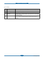
■ Harness Connection table
No
CONNECTION
PIN
SEC Code
1
Main B'd
LSU
16-(10+5)
JC39-00867A
2
Main
HVPS
26-26
JC39-00866A
3
Main
OPE PANEL
4-4
JC39-00868A
4
SMPS
INLET S/W
2-2
JC39-00908A
5
Main B'd
SMPS
16-16
JC39-00894A
6
Main B'd
Sensor(Deve Home)
3-3
JC39-00895A
7
Main B'd
Sensor(Empty)
3-3
JC39-00896A
8
Main B'd
BLDC
10-10
JC39-00899A
9
Main B'd
Cover S/W
2-2
JC39-00900A
10
Main B'd
4-(2+2)
JC39-00901A
11
Main B'd
7-5
JC39-00902A
12
ITB Home Sen I/F
5-(3+2)
JC39-00903A
13
Main
Temp(out)
2-2
JC39-00905A
14
SMPS
FUSER
2
JC39-00907A
15
FUSER
FUSER
1-1
JC39-00500A
16
Main B'd Bracket
Fuser Ass'y GND
1-1
JC39-00496A
17
HVPS
GND WIRE
1-2
JC39-00904A
18
Main
CRUM-JOINT
4-4
JC39-00906A
19
HVPS
EXIT
3-3
20
HVPS
Sensor(Regi)
3-3
JC39-00897A
21
HVPS
Waste Toner Sensor
4-4
JC39-00898A
22
HVPS B'd
23
Main B’d
Service Manual
Eraser Lamp
OPC KEY
ITB Home Sen I/F
ITB Home Sensor
TEMP(Inner)
Sensor
(ITB Tension /OPC Waste)
Wireless LAN PBA
3-6
7-(4+3)
6(5)
JC39-00970A
Samsung Electronics
Disassembly and Reassembly
3.4 Disassembly Procedure
The description of disassembly and reassembly in this manual is listed according to the disassembly
procedures. If you find the certain unit or Assy, please consult the name of unit under the picture.
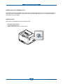
3.4.1 Cover
1. Take out the Cassette.
3. Lift the top cover up.
2. Open the front cover. Remove 2 screws.
4. Remove 1 screw from the rear.
Service Manual
3-7
Samsung Electronics
Disassembly and Reassembly
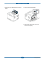
5. Remove the left / right cover by releasing the hooks from the top/bottom/right/left.
Hook
Hook
Service Manual
3-8
Samsung Electronics
Disassembly and Reassembly
3.4.2 ITB
1. Remove the top cover. (Refer to 3.4.1)
3. Hold the ITB handle. Pull out the ITB to the
direction of arrow.
2. Unplug the connector from OPE PBA.
3.4.3 Fuser unit
1. Remove the right cover.
Unplug 2 connector on the main PBA as shown
below.
2. Remove the 4 screw.
Move the shaft to the right as shown
below. And remove the Fuser unit.
Caution - The fuser is very hot. So turn the printer
off and wait until the printer to cool before
replacing it.
Service Manual
3-9
Samsung Electronics
Disassembly and Reassembly
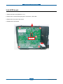
3.4.4 HVPS board
1. Remove the left cover (Refer to 3.4.1).
2. Remove the 5 screws and unplug the 2 connectors, 1 flat cable.
3. Remove the one hook of the center.
4. Release the HVPS board.
Hook
Service Manual
3-10
Samsung Electronics
Disassembly and Reassembly
3.4.5 Main PBA
1. Remove the right cover. (Refer to 3.4.1)
2. Unplug the all connectors. Remove 4 screws. And release the main PBA.
3.4.6 SMPS board
1. Remove the right cover. (Refer to 3.4.1)
2. Unplug the all connectors. Remove 4 screws. And release the SMPS board.
Service Manual
3-11
Samsung Electronics
Disassembly and Reassembly
3.4.7 LSU
1. To remove the LSU from the bottom of the SET,
first remove the harness cover after remove the
2 screws. And remove the 3 screws.
2. Release the LSU unit after remove the 2 Flat
cable.
Harness cover
Harness cover
3.4.8 Holder Pad
1. Remove the sub PBA. And release the Guide
Pick up unit after remove the 4 screws.
Service Manual
2. Release the holder pad after remove the hook
of both side.
3-12
Samsung Electronics
Disassembly and Reassembly
3.4.9 Transfer roller
1. Open the rear cover.
2. Remove the transfer roller Assy by pushing the hooks from the left/right.
Service Manual
3-13
Samsung Electronics
Disassembly and Reassembly
3.4.10 OPE PBA
1. Open the front cover. Remove 2 screws. Lift the top cover up.
2. Remove 1 screw. Unplug 2 connectors. Release the OPE PBA.
Service Manual
3-14
Samsung Electronics
Disassembly and Reassembly
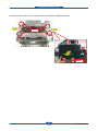
3.4.11 Pick up roller
Before disassembling, remove the Guide Pick up unit. (refer to 3.4.8)
1. Remove the hook from the position A and push to the left side.
2. Separate the Pick up roller Ass’y after release the position B.
3. Remove the hook of the part C, B in sequence.
4. Separate the Pick up rubber.
Service Manual
3-15
Samsung Electronics
Alignment & Troubleshooting
4. Alignment & Troubleshooting
4.1 Alignment and Adjustments
This chapter describes the main functions for service, such as the product maintenance method, the test
output related to maintenance and repair, Jam removing method, and so on.
It includes the contents of manual.
4.1.1. Control Panel
4.1.1.1 Overview
- The CLP-320/325 series printers do not have LCD panel which is used in other color model printers. On the
contrary to other models of color printers, they show the status of the printer only with their LEDs.
- The CLP-320/325 series printers have 3 keys and 6 LEDs. The ‘User Interface’ module handles the
processing of the ‘Key Press’ and ‘LED control’ at different states of the machine.
[1]
[2]
5
1
1
2
2
3
6
3
4
5
4
[1] CLP-320(K)/CLP-321/CLP-325(K)/ CLP-326/CLP-320N(K)/CLP-321N
1
Toner colors
Shows the status of each toner cartridge.
2
Power
You can turn the power on and off with this button.
3
Cancel
Stops an operation at any time and there are more functions.
4
Status LED
5
Print Screen
Demo Print
b
Shows the status of your machine.
a
Prints the displayed screen of your monitor.
Prints a demo page.
a. CLP-320(K)/CLP-321/CLP-325(K)/ CLP-326 only.
b. CLP-320N(K)/CLP-321N only.
Service Manual
4-1
Samsung Electronics
Alignment & Troubleshooting
[2] CLP-325W(K)
1
Toner colors
Shows the status of each toner cartridge.
2
Power
You can turn the power on and off with this button.
3
Cancel
Stops an operation at any time and there are more functions.
4
Status LED
Shows the status of your machine.
Wireless
Shows the status of wireless network. When the LED on, the machine is
connected wirelessly.
WPS
If your wireless access point supports WPS (Wi-Fi Protected Setup™),
you can configure the wireless network connection easily without a
computer.
5
6
Service Manual
4-2
Samsung Electronics
Alignment & Troubleshooting
4.1.1.2 Understanding the control panel
■ Status/Toner colors LEDS
LED
Online/
Error
STATUS
TONER
COLORS LED
DESCRIPTION
Off
All LEDs off
The machine is off-line.
Solid green
All LEDs off
The machine is on-line and can receive data from a computer.
Slowly
blinking
green
All LEDs off
When the Status LED blinks green slowly, the machine is
receiving data from a computer.
Quickly
blinking
green
All LEDs off
When the Status LED blinks green quickly, the machine is
printing data.
Solid green
Corresponding
LED blinks red
Each toner cartridge is near the end of its life.
Corresponding
LED blinks red
successively
The machine is warming up.
All LEDs off
• The cover is open. Close the cover.
• There is no paper in the tray. Load paper in the tray.
• The machine has stopped due to a major error.
• The machine is experiencing system problems requiring
service, such as LSU error, fuser error, or ITB error. Contact
the service representative.
Solid red
Corresponding • A toner cartridge has almost reached its estimated cartridge
LED is solid red lifea. It is recommended to replace the toner cartridge.
• The machine cannot recognize the status of toner cartriges
and the supplies information. Open and close the cover and
check if the machie can operate properly. If the problem
persists, turn the power off and on.
Jam
Blinks red
Corresponding • A minor error has occurred and the machine is waiting for the
LED is solid red error to be cleared. When the problem is cleared, the machine
resumes.
• A small amount of toner is left in the cartridge. The estimated
cartridge lifea of toner is close. Prepare a new cartridge for
replacement. You may temporarily increase the printing quality
by redistributing the toner in the cartridge.
Lights
orange
All LEDs off
A paper jam has occurred.
a. Estimated cartridge life means the expected or estimated toner cartridge life, which indicates the average capacity
of print-outs and is designed pursuant to ISO/IEC 19798. The number of pages may be affected by operating
environment, printing interval, graphics, media type and media size. Some amount of toner may remain in the cartridge
even when red LED is on and the printer stops printing.
Service Manual
4-3
Samsung Electronics
Alignment & Troubleshooting
■ Wireless LED
WIRELESS LED STATUS
Blue
DESCRIPTION
Off
Wireless network is disconnected.
On
Wireless network is connected.
Slowly blinks
The machine starts connecting to a wireless network.
Quickly blinks
• The machine is connecting to access point (or wireless router).
• Wireless network connection is being disconnected.
4.1.1.3 Introducing the useful buttons
■ Print screen button (CLP-320(K)/CLP-321/CLP-325(K)/ CLP-326 only.)
By pressing the Print screen button, you can do the following functions.
FUNCTION
Printing the active window
DESCRIPTION
Press this button and the green LED will start blinking. When the green
LED stops blinking, release the button.
Printing the whole monitor screen Press this button and the green LED will start blinking. Release the
button while it’s blinking.
■ Demo print button (CLP-320N(K)/CLP-321N only.)
It prints a demo page by pressing this button only. The printed page shows the color print quality potential
and overall print characteristics of the machine.
■ Cancel button
By pressing the Cancel button, you can do the following functions.
FUNCTION
DESCRIPTION
Printing demo page
In ready mode, press and hold this button for about 2 seconds until the
status LED blinks slowly, and release.
Printing configuration sheets
In ready mode, press and hold this button for about 5 seconds until the
status LED blinks quickly, and release.
Canceling print job
Press cancel button during printing. The red LED blinks while the print
job is cleared from both the machine and the computer and then the
machine returns to ready mode. This may take some time depending on
the size of the print job.
Service Manual
4-4
Samsung Electronics
Alignment & Troubleshooting
Configuration
Service Manual
4-5
Samsung Electronics
Alignment & Troubleshooting
supplies info
Service Manual
4-6
Samsung Electronics
Alignment & Troubleshooting
network
Service Manual
4-7
Samsung Electronics
Alignment & Troubleshooting
■ WPS button (CLP-325W(K) only.)
This feature automatically detects which WPS (Wi-Fi Protected Setup™) mode your access point uses. By
pushing a button on the wireless LAN router / access point and the machine, you can setup the wireless
network and security settings.
■ Power button
This button must be used to turn the machine on/off.
Turning on the machine
1.Plug in the power cord.
2.Press Power button on the control panel.
Service Manual
4-8
Samsung Electronics
Alignment & Troubleshooting
4.1.2 Jam Removal
TIPS FOR AVOIDING PAPER JAMS
By selecting the correct media types, most paper jams can be avoided. When a paper jam occurs, refer to
the guidelines below
• Ensure that the adjustable guides are positioned correctly.
• Do not overload the tray. Ensure that the paper level is below the paper capacity mark on the inside of the
tray.
• Do not remove paper from the tray while your machine is printing.
• Flex, fan, and straighten paper before loading.
• Do not use creased, damp, or highly curled paper.
• Do not mix paper types in a tray.
• Use only recommended print media.
• Ensure that the recommended side of the print media is facing up in the tray.
4.1.2.1 Clearing Paper Jams
NOTE: To avoid tearing the paper, pull the jammed paper out slowly and carefully. Follow the instructions in
the following sections to clear the jam.
If a paper jam occurs, the status LED on the control panel lights orange. Find and remove the jammed paper.
If paper is jammed in the paper feed area, follow the next steps to release the jammed paper.
In the tray
3. Remove the jammed paper by gently pulling it
straight out.
1. Open and close the front cover. The jammed
paper is automatically ejected from the machine.
If the paper does not eject, go to the next step.
2. Pull out the tray.
If the paper does not eject when you pull, or if
you do not see the paper in this area, check the
fuser area around the toner cartridge.
4. Insert the tray back into the machine until it
snaps into place. Printing automatically resumes.
Service Manual
4-9
Samsung Electronics
Alignment & Troubleshooting
Inside the machine
In the paper exit area
1. Open and close the front cover. The jammed
paper is automatically ejected from the machine.
If the paper does not eject, go to the next step.
1. Gently pull the paper out the output tray.
2. To remove the jammed paper, open the rear
cover.
If you do not see the jammed paper or if there is
any resistance when you pull, stop and go to the
next step.
2. To remove the jammed paper, open the rear
cover.
3. Carefully remove the jammed paper by pulling
in the direction as shown below. Most of the
jammed paper can be removed in this step.
If the paper does not eject when you pull, or if
you do not see the paper in this area, check the
paper exit area.
4. C
lose the rear cover. Make sure that it is
securely closed. Printing automatically resumes.
Service Manual
4-10
Samsung Electronics
2
Alignment & Troubleshooting
3. Carefully remove the paper by pulling in the
direction as shown below. Most of the jammed
paper can be removed in this step.
5. Open the top cover and inner cover.
1
1
2
2
If you cannot find the jammed paper, of if there
is any resistance removing the paper, go to the
next step.
6. Holding the inner cover open, carefully take the
jammed paper out the machine. The inner cover
will then close automatically.
4. Push the fuser levers upwards.
1
2
Service Manual
4-11
Samsung Electronics
Alignment & Troubleshooting
7. Close the top cover. Make sure that it is securely
closed.
8. Push the fuser levers downwards.
1
2
9. Open and then close the rear cover or front
cover to resume printing.
Service Manual
4-12
Samsung Electronics
Alignment & Troubleshooting
4.1.3 Firmware upgrade
1) Connect PC and printer with USB cable.
2) Turn on the power of printer. (Ready Status)
3) Download the firmware file.
Unzip the file.
Drag the f/w file and Drop down on the usblist2.exe.
And then f/w update will be started automatically.
CLP-325N_V1.01.00.00.hd
Drag and Drop
4) Please wait until end reboot.
Service Manual
4-13
Samsung Electronics
Alignment & Troubleshooting
4.1.4 Periodic Defective Image
If an image defects appears at regular intervals on the printed-paper, it is due to a faulty or damaged roller.
Refer to the table below and check the condition of the appropriate roller.
No
Roller
Period
Phenomenon
1
OPC Drum
188.5mm
White and Black Spots
2
Charge Roller
37.7mm
Black Spot and line and Periodic Band
3
Supply Roller
47.5mm
Periodic Band by little difference of density
4
Developing Roller
26.0mm
White Spot, Horizontal black band
5
1 st Transfer Roller
43.8mm
Ghost, Damaged Image by abnormal tranfer
6
2 nd Transfer Roller
54.64mm
Ghost, Damaged Image by abnormal tranfer
7
Pressure Roller
50.3mm
Background
8
Heat Roller
86.4mm
Black Spots or Vertical Black Band
Exit roller
T1 roller
Pressure
roller
Heat roller
OPC
ITB
T2 roller
Charge roller
Supply roller
Deve roller
Regi roller
Pick up roller
Service Manual
4-14
Samsung Electronics
Alignment & Troubleshooting
4.1.5 Using the smart pane program
Smart Panel is a program that monitors and informs you of the machine status, and allows you to customize
the machine’s settings. For Windows and Macintosh, Smart Panel is installed automatically when you install
the machine software. For Linux, you can download Smart Panel from the Samsung website.
■ Understanding Smart Panel
If an error occurs while printing, you can check the error from the Smart Panel.
You can also launch Smart Panel manually. Double-click the Smart Panel icon on the Windows task bar (in
Windows), or Notification Area (in Linux). You can also click it on the status bar (in Mac OS X).
Windows
Double-click this icon in Windows.
Macintosh
Click this icon in Mac OS X.
Linux
Click this icon in Linux.
Or, if you are a Windows user, you can launch it from the Start menu, select Programs or All Programs >
Samsung Printers > your printer driver name > Smart Panel.
If you have already installed more than one Samsung machine, first select the correct machine model
you want in order to access the corresponding Smart Panel.
Right-click (in Windows or Linux) or click (in Mac OS X) the Smart Panel icon and select your machine.
The Smart Panel program displays the current status of the machine, the estimated level of toner remaining
in the toner cartridge(s), and various other types of information. You can also change settings.
1
Toner Level
View the level of toner remaining in the toner cartridge(s). The machine
and the number of toner cartridge(s) shown in the above window may
differ depending on the machine in use. Some machines do not have this
feature.
2
Buy Now
Order replacement toner cartridge(s) online.
3
User’s Guide
View the User’s Guide.
This button changes to Troubleshooting Guide when error occurs. You
can directly open the troubleshooting section in the user’s guide.
Service Manual
4-15
Samsung Electronics
Alignment & Troubleshooting
4
Printer Setting
Configure various machine settings in the Printer Settings Utility window.
Some machines do not have this feature.
If you connect your machine to a network, the SyncThru™ Web
Service window appears instead of the Printer Settings Utility window.
5
Driver Setting
Set all of the machine options you need in the Printer Preferences
window. This feature is available only for Windows.
■ Changing the Smart Panel Program Settings
Right-click (in Windows or Linux) or click (in Mac OS X) the Smart Panel icon and select Options. Select the
settings you want from the Options window.
Service Manual
4-16
Samsung Electronics
Alignment & Troubleshooting
4.1.6 How to use EDC (Engine Diagnostic Control) Mode
EDC Mode is feature that allows the engineer to check the condition of the print engine. It can check the
operating condition of the motors, sensors, solenoids and clutches, measure the High Voltage from the HVPS
and check the operation of the fuser and LSU.
4.1.6.1 Enterence
When trying to check the CLP-320N EDC Mode, additional EDC execution program needed.
[ Procedure of EDC Mode operation ]
a) First, turn on the Power of Printer, wait until Ready state
b) In this state, Run the EDC program on the computer
c) After that, click the menu of screen
d) Then <Motor Test> appears on the initial screen
e) Should you get out of this program, press Exit of screen
4.1.6.2 Keys
Key
Discription
Exit
Close program
Update LCD
Update value (ex : sensor value)
Menu
Move to the top menu
Left/Right arrow
Move test item
Enter
Start testing or select Sub-item
Upper level
Stop testing or the upper menu
4.1.6.3 EDC Map
Service Manual
4-17
Samsung Electronics
Alignment & Troubleshooting
4.1.6.3(a) Motor Test
Item
Discription
Main Motor
If motor lock signal is normal, “Successed” message will be displayed.
When motor lock signal is abnormal, “failed” message will be displayed.
When “Upper Level” is pushed, “off” message will be displayed.
4.1.6.3(b) Solenoid Test
Item
Discription
Dev Clutch
When “select” key is pushed, “Dev Clutch ON” message will be displayed. “Upper Level” is
pushed, ”Dev Clutch Off” message will be displayed.
Relay 1
When “select” key is pushed, “1 Relay ON” message will be displayed. “Upper Level” is
pushed, ”1 Relay Off” message will be displayed on.
Relay 2
When “select” key is pushed, “2 Relay ON” message will be displayed. “Upper Level” is
pushed, ”2 Relay Off” message will be displayed.
Relay 3
When “select” key is pushed, “3 Relay ON” message will be displayed. “Upper Level” is
pushed, “3 Relay Off” message will be displayed.
Y Toner
When “select” key is pushed, “Y Toner ON” message will be displayed. “Upper Level” is
pushed, “Y Toner Off” message will be displayed.
M Toner
When “select” key is pushed, “M Toner ON” message will be displayed. “Upper Level” is
pushed, “M Toner Off” message will be displayed.
C Toner
When “select” key is pushed, “C Toner ON” message will be displayed. “Upper Level” is
pushed, “C Toner Off” message will be displayed.
K Toner
When “select” key is pushed, “K Toner ON” message will be displayed.“Upper Level” is
pushed, “K Toner Off” message will be displayed.
Regi Clutch
When “select” key is pushed, “REGI Clutch ON” message will be displayed. “Upper Level” is
pushed, “REGI Clutch Off” message will be displayed.
T2 Clutch
When “select” key is pushed, “T2 Clutch ON” message will be displayed. “Upper Level” is
pushed, “T2 Clutch Off” message will be displayed.
ITB Clutch
When “select” key is pushed, “ITB Clutch ON” message will be displayed. “Upper Level” is
pushed, “ITB Clutch Off” message will be displayed.
Tray1 Clutch
When “select” key is pushed, “Tray1 Clutch ON” message will be displayed. “Upper Level” is
pushed, “Tray1 Clutch Off” message will be displayed.
Tray2 Clutch
When “select” key is pushed, “Tray1 Clutch ON” message will be displayed. “Upper Level” is
pushed, “Tray1 Clutch Off” message will be displayed.
Regi. Sensor
If actuator is checked by sensor, “Without Paper” message will be displayed.
if not, “With Paper” message will be.
Exit Sensor
If actuator is checked by sensor, “Without Paper” message will be displayed.
if not, “With Paper” message will be.
Waste Box
If waste Box exists , “Installed” message will be displayed.
If not, “Not Installed” message will be.
Service Manual
4-18
Samsung Electronics
Alignment & Troubleshooting
Item
Discription
Cover
If cover is opened, " Opened“ message will be displayed.
If not, "Closed" message will be.
Tray1 Empty
If paper exists in the tray, "With Paper" will be displayed.
If not, "Without Paper" message will be.
Tray2 Empty
If paper exists in the tray, "With Paper" will be displayed.
If not, "Without Paper" message will be.
4.1.6.3(b) Solenoid Test
Item
Discription
LSU Motor
If LSU motor lock signal is normal, "Successed" message will be displayed.
When LSU motor lock signal is abnormal , “failed” message will be displayed.
When “Upper Level” is pushed, “off” message will be displayed.
LSU Power
When “select” key is pushed, “LSU Power On” message will be displayed.
If not, “LSU Power Off” message will be.
Laser Diode
When select key is pushed, Laser Diode On message will be displayed.
If not, Laser Diode Off message will be.
Eraser
When select key is pushed, Eraser On message will be displayed .
If not, Eraser Off message will be.
Fuser
When select key is pushed, Fuser On message will be displayed.
If not, Fuser Off message will be.
Service Manual
4-19
Samsung Electronics
Alignment & Troubleshooting
4.1.6.3(d) HVPS Test
Item
Discription
Charger
When “select” key is pushed, “DUTY : x%*” message will be displayed.
And then Left/Right arrow is selected, x% is increased or decreased.
And “DUTY : x%” message will be displayed. * is disappeared.
And then “select” key is pushed, x%*” message will be displayed.
When “Upper Level” is pushed, * is disappeared.
T1
When “select” key is pushed, “DUTY : x%*” message will be displayed.
And then Left/Right arrow is selected, x% is increased or decreased.
And “DUTY : x%” message will be displayed. * is disappeared.
And then “select” key is pushed, x%*” message will be displayed.
When “Upper Level” is pushed, * is disappeared.
T2
When “select” key is pushed, “DUTY : x%*” message will be displayed.
And then Left/Right arrow is selected, x% is increased or decreased.
And “DUTY : x%” message will be displayed. * is disappeared.
And then “select” key is pushed, x%*” message will be displayed.
When “Upper Level” is pushed, * is disappeared.
T2 REVERSE
When “select” key is pushed, “T2 REVERSE On” message will be displayed.
If not, “T2 REVERSE Off“ will be.
Dev DC
When “select” key is pushed, “DUTY : x%*” message will be displayed.
And then Left/Right arrow is selected, x% is increased or decreased.
And “DUTY : x%” message will be displayed. * is disappeared.
And then “select” key is pushed, x%*” message will be displayed.
When “Upper Level” is pushed, * is disappeared.
Dev AC Vpp
When “select” key is pushed, “DUTY : x%*” message will be displayed.
And then Left/Right arrow is selected, x% is increased or decreased.
And “DUTY : x%” message will be displayed. * is disappeared.
And then “select” key is pushed, x%*” message will be displayed.
When “Upper Level” is pushed, * is disappeared.
Dev AC
When “select” key is pushed, “DUTY : x%*” message will be displayed.
And then Left/Right arrow is selected, x% is increased or decreased.
And “DUTY : x%” message will be displayed. * is disappeared.
And then “select” key is pushed, x%*” message will be displayed.
When “Upper Level” is pushed, * is disappeared.
Charger
Duty : 50% -> “-789V”, Range : -81V ~ -1689V
T1
Duty : 50% -> “1159V”,
T2
Duty : 50% -> “2552V”, Range : 264V ~ 4730V
Supply DC
Duty : 50% -> “-269V”, Range : -1V ~ -591V
AC, Vpp
Duty : 50%-> “1210V” , Range : 800V ~ 2160V
Service Manual
Range : 122V ~ 2188V
4-20
Samsung Electronics
Alignment & Troubleshooting
4.1.6.3(e) Maintenance
Item
Discription
Fuser
When “select” key is pushed, “Initialized” message will be displayed.
When “Upper Level” is pushed, “Off” message is disappeared.
Transfer
When “select” key is pushed, “Initialized” message will be displayed.
When “Upper Level” is pushed, “Off” message is disappeared.
FCF Pick Up Roll
When “select” key is pushed, “Initialized” message will be displayed.
When “Upper Level” is pushed, “Off” message is disappeared.
SCF Pick Up Roll
When “select” key is pushed, “Initialized” message will be displayed.
When “Upper Level” is pushed, “Off” message is disappeared.
ITB
When “select” key is pushed, “Initialized” message will be displayed.
When “Upper Level” is pushed, “Off” message is disappeared.
Service Manual
4-21
Samsung Electronics
Alignment & Troubleshooting
4.2 Troubleshooting
4.2.1 Procedure of Checking the Symptoms
Before attempting to repair the printer first obtain a detailed description of the problem from the customer.
Power On
Green LED on?
- No Power
- Power Module error
- Main PBA error
- Panel PBA error
Ready or
Power save
Error LED ON?
Refer to
4.1.8 LED Status
Error Message
Test Print
printing
Quality is
Nomal?
Refer to "Solution
of Image Problem"
END
Service Manual
4-22
Samsung Electronics
Alignment & Troubleshooting
4.2.2 Troubleshooting Checklist
If the printer is not working properly, consult the following checklist. If the printer does not pass a step, follow
the corresponding troubleshooting suggestions.
Status
Response
Make sure that the Status LED
on the control panel is green and
“Ready” is shown on the Smart
Panel program window.
• If the Status LED is off, check the power cord connection. Check the power
switch. Check the power source by plugging the power cord into another
outlet.
• If the Status LED blinks or lights red, solve the problems.
Print a demo page to verify
that the printer is feeding paper
correctly.
• If a demo page does not print, check the paper supply in the paper tray.
• If the paper jams in the printer, go to “Clearing Paper Jams”
Check the demo page to see if it
is printed correctly.
If there is a print quality problem, go to “Solving Print Quality Problems”
Print a short document from a
software application to verify that
the computer and printer are
connected and communicating
correctly.
• If the page does not print, check the cable connection between the printer
and the computer.
•C
heck the print queue or print spooler to see if the printer has been
paused.
•C
heck the software application to ensure that you are using the proper
printer driver and communication port. If the page is interrupted during
printing, go to “Solving General Printing Problems”
If completing the checklist
does not resolve the printer
problem, check the following
troubleshooting sections.
• See “Solving General Printing Problems”
• See “Solving Print Quality Problems”
• See “Common Windows Problems”
• See “Common Macintosh Problems”
• See “Common Linux Problems”
Service Manual
4-23
Samsung Electronics
Alignment & Troubleshooting
4.2.3 Solving General Printing Problems
For problems with the operation of your printer, refer to the table for suggested solutions..
Description
The printer does not print.
Check the power cord connections.
Check the power switch and the
power source.
The printer is not
receiving power.
The printer is not
selected as the default printer.
Select Samsung CLX-3185 series
as your default printer.
Check the printer
for the following:
The printer cover is not closed.
Paper is jammed.
No paper is loaded.
A toner cartridge is not installed.
Close the printer cover.
Clear the paper jam.
Load paper.
Install the toner cartridge.
Check the message on the Smart
Panel program window, add paper
to the tray and press the Stop
button on the control panel.
The printer may be in
manual feed mode and out of paper.
The connection cable
between the computer and the
printer is not connected
properly.
Disconnect the printer cable and
reconnect it.
Countinue..
4-24
Service Manual
Countinue..
Samsung Electronics
If possible, attach the cable to
between the computer and the
printer is not connected
properly.
Disconnect the printer cable and
reconnect it.
Alignment & Troubleshooting
Countinue..
Countinue..
Service Manual
The connection cable
between the computer and the
printer is defective.
If possible, attach the cable to
another computer that is working
properly and try to print a
document. You can also try using a
different printer cable.
The port setting is incorrect.
Check the Windows printer setting
to make sure that the print job is
sent to the correct port. If the
computer has more than one port,
make sure that the printer is
attached to the correct one.
The printer may be
configured incorrectly.
Check the printer properties to
ensure that all of the print settings
are correct.
The printer driver
may be incorrectly installed.
Reinstall the printer driver; see the
Software Section. Try printing a
test page.
The printer is malfunctioning.
Check the LEDs on the control
panel to determine if the printer is
indicating a system error.
4-25
Samsung Electronics
Alignment & Troubleshooting
Description
Paper does not feed into the printer..
Paper has been loaded incorrectly.
Remove paper from the tray and
reload it correctly.
Check that the paper guides are
set correctly.
There is too much paper in the tray.
Remove excess paper from the
tray.
Use only paper that meets printer
specifications.
The paper is too thick.
Service Manual
4-26
Samsung Electronics
Alignment & Troubleshooting
Description
A print job is extremely slow.
Reduce the complexity of the
page(s) or try adjusting the print
quality settings.
Adjust the print quality settings,
such as reducing the resolution. If
you have set the resolution to
2400dpi [Best], change it to 1200dpi
[Normal] or 600dpi [Draft]. See the
Software section.
Change the port setting to the USB
or network port to improve print
speed. Your printer prints A4-sized
paper at 16 ppm in black and white
mode and 4 ppm in color mode.
The job may be very complex.
From the Start menu, choose
Settings and Printers. Right-click
the Samsung CLP-31x series
printer icon, choose Properties,
click the Details tab, and then
choose the Spool Settings button.
Select the desired spool setting.
If using Windows 98/Me, the
Spooling Setting may be set
incorrectly.
Service Manual
4-27
Samsung Electronics
Alignment & Troubleshooting
Description
Half the page is blank.
Change the page orientation in
your application. For details, see
the Software Section.
The page orientation
setting may be incorrect.
Ensure that the paper size in the
printer driver settings matches the
paper in the tray.
Or, ensure that the paper size in the
printer driver settings matches the
paper selection in the software
application settings you use.
The paper size and
the paper size settings do not
match.
Service Manual
4-28
Samsung Electronics
Alignment & Troubleshooting
Description
The paper keeps jamming.
Remove excess paper from the tray.
Check that the paper guides are set
correctly.
There is too much
paper in the tray.
Service Manual
An incorrect type of
paper is being used.
Use only paper that meets printer
specifications.
There may be debris
inside the printer.
After opening the front cover,
remove the imaging unit and then
clear the debris.
4-29
Samsung Electronics
Alignment & Troubleshooting
Description
The printer prints, but the text is wrong, garbled, or incomplete.
Disconnect and reconnect the
printer cable. Try a print job that you
have already printed successfully. If
possible, attach the cable and
printer to another computer and try
a print job that you know works.
Finally, try a new printer cable.
The printer cable is
loose or defective.
Check the application's printer
selection menu to ensure that your
printer is selected.
The wrong printer
driver was selected.
The software
application is malfunctioning.
Try printing a job from another
application.
Exit Windows and reboot the
computer. Turn the printer off and
then back on again.
The operating system
is malfunctioning.
Service Manual
4-30
Samsung Electronics
Alignment & Troubleshooting
Description
The print quality of photos is not good.
Images are not clear.
The resolution is set
to 1200dpi [Normal] or 600dpi [Draft].
Change the resolution to 2400dpi
[Best] and then try printing again.
If you increase the photo size in the
software application, the resolution
will be reduced. Reduce the photo
size.
The resolution of the
photo is very low.
Service Manual
4-31
Samsung Electronics
Alignment & Troubleshooting
4.2.4 Solving Print Quality Problems
Dirt inside of the printer or improper paper loading may reduce print quality. See the table below to
troubleshoot problems.
1) Light or faded print
AaBbCc
AaBbCc
AaBbCc
AaBbCc
AaBbCc
AaBbCc
AaBbCc
AaBbCc
AaBbCc
1. If a vertical white streak
AaBbCc
or faded area appears on
the page
AaBbCc
AaBbCc
AaBbCc
AaBbCc
AaBbCc
AaBbCc
AaBbCc
AaBbCc
AaBbCc
AaBbCc
AaBbCc
AaBbCc
A the
Bb
C type and quality.
Checka
paper
AaBbCcc
AaBbCc
2. The paper may not meet
paper specifications
3. A combination of
faded or smeared defects may
indicate that the printer
needs cleaning
AaBbCc
AaBbCc
AaBbCc
4. High voltage terminal is
AaBbCc
contaminated by the
toner. So the
contact is unstable.AaBbCc
Or the output of
the HVPS is abnormal.
AaBbCc
AaBbCc
AaBbCc
AaBbCc
AaBbCc
Service Manual
A
A
The toner supply is low. You may be
able to temporarily extend the toner
cartridge life. If this does not
improve print quality, install a new
toner cartridge.
Check the inside for the printer.
A
Clean the HVPS terminal.
If the problem persists, replace
the HVPS board.
AaBbCc
AaBbCc
AaBbCc
AaBbCc
AaBbCc
4-32
Samsung Electronics
AaBbCc
AaBbCc
AaBbCc
AaBbCc
AaBbCc
2) Toner specks
AaBbCc
AaBbCc
Alignment & Troubleshooting
AaBbCc
AaBbCc
AaBbCc
AaBbCc
AaBbCc
AaBbCc
AaBbCc
AaBbCc
AaBbCc
AaBbCc
AaBbCc
AaBbCc
AaBbCc
The paper may not meet specifications
AaBbCc
AaBbCc
AaBbCc
AaBbCc
AaBbCc
AaBbCc
AaBbCc
AaBbCc
AaBbCc
AaBbCc
Service Manual
A
Check the paper type and quality.
A
AaBbCc
AaBbCc
AaBbCc
AaBbCc
AaBbCc
AaBbCc
AaBbCc
AaBbCc
AaBbCc
AaBbCc
A
4-33
Samsung Electronics
AaBbCc
AaBbCc
AaBbCc
AaBbCc
AaBbCc
3) Dropouts
AaBbCc
AaBbCc
AaBbCc
AaBbCc
AaBbCc
Alignment & Troubleshooting
AaBbCc
AaBbCc
AaBbCc
AaBbCc
1. If generally AaBbCc
rounded,
faded areas occur randomly
on the page
AaBbCc
AaBbCc
AaBbCc
AaBbCc
AaBbCc
2. The moisture
content of the paper is uneven
or the paper has moist spots
on its surface.
A
3. The paper lot is bad.
4. The toner cartridge may be defective.
Service Manual
4-34
AaBbCc
AaBbCc
AaBbCc
AaBbCc
AaBbCc
A
A single sheet of paper may be
defective. Try reprinting the job.
Try a different brand of paper.
The manufacturing process can
cause some areas to reject toner.
Try a different kind or brand of paper.
See "Vertical repetitive defects" on
the next page.
Samsung Electronics
AaBbCc
AaBbCc
AaBbCc
AaBbCc
AaBbCc
AaBbCc
AaBbCc
AaBbCc
A
AaBbCc
AaBbCc
AaBbCc
AaBbCc
Alignment & Troubleshooting
AaBbCc
AaBbCc
AaBbCc
AaBbCc
AaBbCc
4) Vertical lines
AaBbCc
AaBbCc
AaBbCc
AaBbCc
AaBbCc
A
1. If black vertical
streaks appear on the page
A imaging unit has probably been
scratched.
Remove the imaging unit and install
a new one.
2. If white vertical
lines appear on the page
Clean the inside of the printer. If you
still have the same problems,
replace the imaging unit with a new
one.
3. Foreign matter stuck
onto the window of internal lenses
of LSU mirror.
Service Manual
4-35
Clean the LSU window with
recommended cleaner(IPA).
Samsung Electronics
Alignment & Troubleshooting
5) Color or Black background
AaBbCc
AaBbCc
AaBbCc
AaBbCc
AaBbCc
1. If the amount of
background shading becomes
unacceptable, the procedures below
may fix the problem.
AaBbCc
AaBbC
AaBbCcc
AaBbCc
AaBbenvironment
2. heck the printer's
Cc
AaBbCc
AaBbCc
AaBbCc
AaBbCc
AaBbCc
3. No charge voltage in the HVPS board.
Change to lighter weight paper.
1. very dry (low humidity) or high
humidity (higher than 80% RH)
conditions can increase the
amount of background shading.
2. Remove one of the old toner
cartridges and install a new one.
Clean the high voltage charge
terminal.
If the problem persists, replace the
HVPS board.
A
AaBbCc
AaBbCc
AaBbCc
AaBbCc
AaBbCc
A
Service Manual
A
4-36
Samsung Electronics
AaBbCc
AaBbCc
AaBbCc
AaBbCc
AaBbCc
Alignment & Troubleshooting
6) Toner smear
A
AaBbCc
AaBbCc
AaBbCc
AaBbCc
AaBbCc
1. Clean the inside of the printer.
2. Check the paper type and quality.
3. Remove the imaging unit and
install a new one.
1. Toner smear
A
AaBbCc
AaBbCc
AaBbCc
AaBbCc
AaBbCc
AaBbCc
AaBbCc
AaBbCc
AaBbCc
AaBbCc
A
Service Manual
4-37
Samsung Electronics
AaBbCc
AaBbC
AaBbCcc
AaAlignment
BbCc & Troubleshooting
AaBbCc
7) Vertical repetitive defects
AaBbCc
AaBbCc
AaBbCc
AaBbCc
AaBbCc
A
A
1. If marks
repeatedly appear on the
printed side of the page at
even intervals
Clean the inside of the printer.
After cleaning the inside of the
printer, if you still have the same
problems, install a new toner
cartridge of the problem color.
AaBbCc
AaBbCc
AaBbCc
AaBbCc
If the
defects occur on the back of
the page,
the problem will likely
AaBbCc
2. Parts of the printer
may have toner on them.
correct itself after a few more pages.
3. The fusing assembly
may be damaged.
Service Manual
Contact a service representative.
4-38
Samsung Electronics
AaBbCc
AaBbCc
AaBbCc
AaBbCc
Alignment & Troubleshooting
8) Background scatter
A
Service Manual
A
AaBbCc
AaBbCc
AaBbCc
AaBbCc
AaBbCc
The paper may be too damp. Try
printing with a different batch of
paper. Do not open packages of
paper until necessary so that the
paper does not absorb too much
moisture.
1. Background
scatter results from bits of
toner distributed on the
printed page.
2. If background scatter
occurs on an envelope.
Change the printing layout to avoid
printing over areas that have
overlapping seams on the reverse
side. Printing on seams can cause
problems.
3. If background
scatter covers the entire surface
area of a printed page
Adjust the print resolution through
your software application or via the
printer properties window.
4-39
Samsung Electronics
AaBbCc
AaBbC
AaBbCcc
AaAlignment
BbCc & Troubleshooting
AaBbCc
9) Misformed characters
A
AaBbCc
AaBbCc
AaBbCc
AaBbCc
AaBbCc
1. If characters are
improperly formed and producing
hollowed images
A
Service Manual
2. If characters are
improperly formed and producing
a wavy effect.
4-40
The paper stock may be too slick.
Try a different paper.
AaBbCc
AaBbCc
AaBbCc
AaBbCc
The printer may need service.
AaBbCc
Verify
that it also occurs on a demo
page.
Samsung Electronics
A
Alignment & Troubleshooting
10) Page skew
AaBbCc
AaBbCc
AaBbCc
AaBbCc
AaBbCc
Ensure that the paper is loaded
properly.
1. Page skew
A
2. The paper may not meed
specifications
Check the paper type and quality.
3. Ensure that the paper
or other material is loaded correctly
The guides are not too tight or too
loose against the paper stack.
AaBbCc
AaBbCc
AaBbCc
AaBbCc
AaBbCc
Service Manual
4-41
Samsung Electronics
AaBbCc
AaBbCc
AaBbCc
AaBbCc
aBborCwave
11)ACurl
c
Alignment & Troubleshooting
A
Ensure that the paper is loaded
properly.
1. Curl or wave
AaBbCc
AaBbCc
2. Check the paper type and quality.
AaBbCc
AaBbCc
AaBbCc
Also try rotating the paper 180¡ in
the tray.
3. Turn the stack of
paper over in the tray.
Service Manual
Both high temperature and high
humidity can cause paper curl.
4-42
Samsung Electronics
A
Alignment & Troubleshooting
12) Wrinkles or creases
AaBbCc
AaBbCc
AaBbCc
AaBbCc
AaBbCc
1. Wrinkles or creases
Check the paper type and quality.
2. The paper may not meed
specifications
Also try rotating the paper 180¡ in
the tray.
3. Turn the stack of paper
over in the paper tray.
Service Manual
Ensure that the paper is loaded
properly.
4-43
Samsung Electronics
13) Back of printouts aredirty
AaBbCc
AaBbCc
Alignment
& Troubleshooting
AaBbCc
AaBbCc
AaBbCc
1. Does character
exist less than 2% per a page, and
hasn't it been used long time?
2. Does recycle paper be used?
The B/S is not guaranteed if using
recycle paper.
Replace the developer when the life
span of it has been ended.
3. Has the life span of the
developer ended?
4. Is the movement
(Up and Down) of the transfer
roller smooth?
Clean the bushing part of the
transfer roller.
If the problem is still not solved,
replace the developer.
5. Is the HVPS normal?
Service Manual
The toner cartridge is basically
designed to print 3,000 sheets with
5% image. If it prints more than
3,000 sheets (around 5,000 sheets)
with 2% image, a background can
be occurred.
4-44
Samsung Electronics
Alignment & Troubleshooting
14) Solid Color or Black pages
A
Remove the toner cartridge and
reinsert.
1. The toner cartridge may
not be installed properly.
2. The toner cartridge may
be defective and need
replacing.
A
Install a new toner cartridge.
3. The printer may require repair.
Change HVPS.
AaBbCc
AaBbCc
AaBbCc
AaBbCc
AaBbCc
Service Manual
4-45
Samsung Electronics
A
Alignment & Troubleshooting
15) Loose toner
Clean the inside of the printer.
1. Loose toner
A
AaBbCc
AaBbCc
AaBbCc
AaBbCc
AaBbCc
Check the paper type and quality.
2. The paper may not meed
specifications
3. The Toner Cartridge
may be defective and
need replacing.
Install a new toner cartridge.
4. If the problem persists,
the printer may require repair.
Service Manual
4-46
Contact a service representative.
Samsung Electronics
Alignment & Troubleshooting
16) Character Voids
A
1. Character voids are
white areas within characters that should
be solid black
AaBbCc
AaBbCc
AaBbCc
AaBbCc
AaBbCc
Service Manual
4-47
1. You may be printing on the wrong
surface of the paper. Remove the
paper and turn it over.
2. The paper may not meet paper
specifications.
Samsung Electronics
A
Alignment & Troubleshooting
17) Horizontal stripes
AaBbCc
AaBbCc
AaBbCc
AaBbCc
AaBbCc
1. If horizontally
aligned color or black streaks or
smears appear
2. A toner cartridge may be defective.
Service Manual
4-48
A toner cartridge may be installed
improperly.
Remove the toner cartridge and
reinsert.
Install a new toner cartridge.
Samsung Electronics
AaBbCc
AaBbCc
AaBbCc
AaBbCc
18)AaBbCc
Curl
Alignment & Troubleshooting
1. If the printed paper is
curled or paper does not feed into
the printer
Service Manual
4-49
Turn the stack of paper over in the
paper tray. Also try rotating the
paper 180¡ in the tray.
Samsung Electronics
Alignment & Troubleshooting
4.2.5 Common Windows Problems
Exit all software applications. Remove all
software from the StartUp Group, then
restart Windows. Reinstall the printer driver.
"File in Use" message appears
during installation.
Ensure that all cables are connected
correctly and the printer is on.
If bi-directional communication is not
turned on in the driver, it will also cause
this message.
"Error Writing to LPTx"
message appears.
"General Protection Fault",
"Exception OE", "Spool32", or "Illegal
Operation" messages
appear.
Close all other applications, reboot
Windows and try printing again.
These messages may appear during printing.
Just keep waiting until the printer finishes
printing. If the message appears in standby
mode or after printing has been completed,
check the connection and/or whether an
error has occurred.
"Fail To Print", "A printer
timeout error occurred."
messages appear.
NOTE: Refer to the Microsoft Windows 98/Me/NT 4.0/2000/2003/XP User’s Guide that came with your PC
for further information on Windows error messages.
Service Manual
4-50
Samsung Electronics
Alignment & Troubleshooting
4.2.6 Common Macintosh Problems
The printer does not print a
document from Acrobat Reader.
You should change the Print Method option
to Print as Image when you print from
Acrobat Reader.
The document has
printed, but the print job has not
disappeared from the spooler in
Mac OS 10.3.2.
Update your Mac OS to OS 10.3.3 or higher.
Service Manual
4-51
Samsung Electronics
Alignment & Troubleshooting
4.2.7 Common Linux Problems
I can't change settings in the
configuration tool.
You need to have administrator privileges to be able
to change global settings.
I am using the KDE
desktop but the configuration tool
and LLPR won't start.
You may not have the GTK libraries installed. These
usually come with most Linux distributions, but you
may have to install them manually. Refer to your
distribution's installation manual for more details
about installing additional packages.
I just installed this
package but can't find entries in
the KDE/ Gnome menus.
I can't make a printer
the system default.
Continue..
Service Manual
Some versions of the KDE or GNOME desktop
environments may require that you restart your
session for the changes to take effect.
In some conditions, it may not be possible to change
the default queue. This happens with some variants
of LPRng, especially on recent RedHat systems that
use the "printconf" database of queues.
When using printconf, the /etc./printcap file is
automatically refreshed from the database of printers
managed by the system (usually through the
"printtool" command), and the queues in /etc./
printcap.local are appended to the resulting file. The
default queue in LPRng is defined as the first queue
in /etc./printcap, and therefore it is not possible for
the Linux Printer Package to change the default when
some queues have otherwise been defined using
printtool.
LPD systems identify the default queue as the one
named "lp". Thus, if there is already a queue by this
name, and if it doesn't have an alias, then you won't
be able to change the default. To work around this,
you can either delete the queue or rename it by
manually editing the /etc./printcap file.
4-52
Samsung Electronics
Alignment & Troubleshooting
Continue..
The N-up setting
does not work correctly for some of my
documents.
I am using BSD lpr
(Slackware, Debian, older
distributions) and some options chosen
in LLPR don't seem to
take effect.
I am trying to print a document in
Landscape mode, but it prints
rotated and cropped.
Some pages come
out all white (nothing is printed), and
I am using CUPS.
I can't print to an SMB (Windows) printer.
The N-up feature is achieved through postprocessing of the PostScript data that is sent to the
printing system. However, such post-processing can
only be adequately achieved if the PostScript data
conforms to the Adobe Document Structing
Conventions. Problems may arise when using N-up
and other features that rely on post-processing if the
document being printed isn't compliant.
Legacy BSD lpr systems have a hard limitation on
the length of the option string that can be passed to
the printing system. As such, if you selected a
number of different options, you may have exceeded
the length of the options and some of your choices
won't be passed to the programs
responsible for implementing them. Try to select
fewer options that deviate from the defaults, to save
on memory usage.
Most Unix applications that offer a Landscape
orientation option in their printing options will
generate correct PostScript code that should be
printed as is. In that case, you need to make sure
that you leave the LLPR option set to its default
Portrait setting, to avoid unwanted rotations of the
page that would result in cropped output.
If the data being sent is in Encapsulated PostScript
(EPS) format, some earlier versions of CUPS
(1.1.10 and before) have a bug preventing them from
being processed correctly. When going through
LLPR to print, the Printer Package will work around
this issue by converting the data to regular PostScript.
However, if your application bypasses LLPR and
feeds EPS data to CUPS, the document may not
print correctly.
To be able to configure and use SMB-shared printers
(such as printers shared on a Windows printer), you
need to have a correct installation of the SAMBA
package that enables that feature. The "smbclient"
command should be available and usable on your
system.
Continue..
Service Manual
4-53
Samsung Electronics
Alignment & Troubleshooting
Continue..
My application seems to
be frozen while LLPR is running.
How do I specify the IP
address of my SMB server?
Some documents come out
as white pages when printing.
I have CUPS and some
options (such as N-up) seem to be always
enabled even though I don't
choose them in LLPR.
I configured a printer to
print to a file, but I get "Permission
denied" errors.
Most Unix applications will expect a command like
the regular "lpr" command to be non-interactive and
thus return immediately. Since LLPR is waiting for
user input before passing the job on to the print
spooler, very often the application will wait for the
process to return, and thus will appear to be frozen
(its windows won't refresh). This is normal and the
application should resume functioning correctly after
the user exits LLPR.
It can be specified in the "Add Printer" dialogue of
the configuration tool, if you don't use the CUPS
printing system. Unfortunately, CUPS currently
doesn't allow you to specify the IP address of SMB
printers, so you will have to be able to browse the
resource with SAMBA in order to be able to print.
Some versions of CUPS, especially those shipped
with Mandrake Linux before the 8.1 release, have
some known bugs when processing PostScript
output from some applications. Try upgrading to the
latest version of CUPS (at least 1.1.14). Some RPM
packages for the most popular distributions are
provided as a convenience with this Linux Printing
Package.
There may be some local options defined in your ~/ .
lpoptions file, which are manipulated by the lpoptions
command. These options are always used if not
overridden by LLPR settings. To get rid of all options
for a printer, run the following command, replacing
"printer" with the name of the queue:
lpoptions -x printer
Most printing systems will not run as the super-user
but as a special user (usually "lp"). Therefore, make
sure that the file you have chosen to print to is
accessible to the user owning the spooler daemon.
Continue..
Service Manual
4-54
Samsung Electronics
Alignment & Troubleshooting
Continue..
On my PCL (or GDI)
printer, I sometimes get error messages
printing instead of my
document.
Unfortunately, some Unix applications may generate
non-compliant PostScript output that may not be
supported by Ghostscript, or even the printer itself in
PostScript mode. You can try to capture the output to
a file and view the results with Ghostscript (gv or
ghostview will allow you to do so interactively) and
see if you get error messages. However, since the
application is probably at fault, contact your software
vendor to inform them of the issue.
Some color images come out all black.
This is a known bug in Ghostscript (until GNU
Ghostscript version 7.05) when the base color space
of the document is indexed color space and it is
converted through CIE color space. Because
Postscript uses CIE color space for Color Matching
System, you should upgrade Ghostscript on your
system to at least GNU Ghostscript version 7.06 or
later. You can find recent Ghostscript versions at
www.ghostscript.com.
Service Manual
4-55
Samsung Electronics
Alignment & Troubleshooting
4.2.8 Major Problems Trouble shooting
1) Multi-Feeding
Description
Multiple sheets of paper are fed at once.
1. Solenoid malfunction
(the solenoid does not work properly)
Replace the solenoid if necessary.
2. Pad-Friction is
contaminated with foreign matter.(oil...)
Clean the pad friction with soft clothe
dampened with IPA(Isopropyl Alcohol).
Use the smooth paper.
3. The face of paper is blended.
Service Manual
4-56
Samsung Electronics
Alignment & Troubleshooting
2) No Power
Description
When system power is turned on, The LCD and status LED on the operator panel do
not come on.
1. Check if the power input
and SMPS output are normal.
Replace the power supply cord or SMPS.
2. Check the inferiority
of OPE Unit if the LCD of Panel does
not appear after normal
warmingup.
Service Manual
Replace the OPE unit.
4-57
Samsung Electronics
Alignment & Troubleshooting
3) Fuser error
a) Low heat error
"Error #U1-1211 Turn off then on"
message has occurred.
Lamp open?
(For 110V : 1.35±1 ohm
For 220V : 4.7±1 ohm)
Yes
Change Fuser Lamp
4713-001243
Yes
Change Fuser Lamp
4713-001243
NO
Lamp Short?
NO
Yes
AC-Harness Short?
AC-Harness Change
NO
Thermostat Open?
Yes
Replace Thermostat
4712-001031
Yes
Replace Thermostat
1404-001447
Yes
Replace Thermostat
1404-001447
NO
Thermostat Pollution, Bend?
NO
Thermostat Resistance Defect?
(300~450kohm @ 25℃)
Replace Fuser & recheck
The SMPS and Main B'd
could be suspect
NO
Service Manual
4-58
Samsung Electronics
Alignment & Troubleshooting
b) Low heat error
"Error #U1-2121 Turn off then on"
message has occurred.
Lamp open?
(For 110V : 1.35±1 ohm
For 220V : 4.7±1 ohm)
Yes
Change Fuser Lamp
4713-001243
Yes
Replace Thermistor
1404-001447
Yes
Replace Thermistor
1404-001447
NO
Thermostat cannot be
cleaned and/or bent?
NO
Thermostat Resistance Defect?
(300~450kohm @ 25℃)
Replace Fuser & recheck
The SMPS and Main B'd
could be suspect
NO
Service Manual
4-59
Samsung Electronics
Service Manual
5-1
Type 2
1W
5p
4p
4p
4p
4p
3p
2p
3p
3p
3p
2p
Joint
Themistor
Fuser Lamp
2p
SMPS
Samsung Confidential
1
CRUM Y
CRUM C
CRUM M
CRUM Y
Deve Clutch
Regi Clutch
ITB Cutch
T2 Clutch
Pickup Clutch
Fuser Clutch
Fuser
Ground Wire
LSU
5p
2p
4p
6p
single beam 11p
DQ[15:0]
ADDR[8:1]
nRD, nWR,
nCS
DATA[15:0]
ADDR[24:1]
DATA[15:0]
SCL
Clock
USB
USB2.0
DDR : USB(32MB) / NW(256MB)
12MHz
Vclk
zzjn
PLL
Local Controller
Mclk
HPVC
LSU
Controller
PWM 8ch
ADC 8ch
Image Processor
Step
Motor
I2C
UART
MAC
GPIO
RAM Controller
Jupiter5
ARM9 – 360MHz
Flash : USB(2MB) / NW(32MB)
ISP1761
(Wireless )
P. Flash
EEPROM
CLP-325 8KB
CLP-320N 64KB
CLP-325W 64KB
SDA
MAC_TXD[3:0]
MAC_RXD[3:0]
25MHz
(NW & W-less)
N/W
BCM5241
KMLG
CKE, nCS0 , nRAS, nCAS, WE
DM0~1, nDQS0~1, DQS1,
ODT0, nDDR_CLK0, BA0~1
SA[12:0], BA0,1
DDR2
32MB(USB)
256MB
(NW & W-less)
Main B’d
Tissot Series
4p
2p
18p FFC
26p FFC
Block Diagram of Tissot
2p
2p
3p
3p
2p
2p
7p
1
OPC
PTL LAMP
+24V Cover Open S/W
pG{U
ITB Home Sensor
BLDC Motor
(Main)
Waste Toner RX
Waste Toner TX
Sensor (Exit)
Sensor (Regi
(Regi))
Ground Wire(225mm)
Sensor (Empty)
Sensor (Deve
(Deve Home)
OPE Panel Display
(LED & Keys)
5V Switch
10p
T1
T2
Charger
Supply
Deve Bias
HVPS
3p
3p
System Diagram
5. System Diagram
5.1 Block Diagramg
Samsung Electronics
o
}
w
z
X
Y
Z
X
Y
Z
[
\
]
^
_
`
XW
XX
XY
XZ
X[
X\
X]
X^
X_
X`
YW
YX
YY
YZ
Y[
Y\
Y]
X
k
n
u
k
R\}
uylnp
knuk
~
[ Z Y
~~
R
\
}
{ y
juZ
[GZGYGX
~
\
s
z
|
knuk
\}sz|
}kvXw
X]
RY[}
t jsrsz|tv{ XY
v ylhksz| XZ
{
v sz|tv{lu X[
X\
y
knuk
XX
skvusz|
skwv~lyX
knuk
knuk
zosz|X
ozujX
}kvXu
X
Y
Z
[
\
]
^
_
`
XW
m|zly
shtw
ju
X
Y
Z
[
\
]
^
_
`
XW
XX
XY
XZ
X[
X\
X]
knuk
\}sz|
}kvXw
X[
juXX
[
k
n
u
k
Y
[GZGYGX
Z
Y k
[ n
} u
h k
X
z
t
w
z
\
}
ztwzwv~ly
knuk
Y[}h
sz|tv{lu
ylhksz|
jsrsz|tv{
uj
skvusz|
skwv~lyX
knuk
knuk
zosz|X
ozujX
}kvXu
ztwz
X_
YX
ju
o}wz
j v
RY[}h
kl}ylsh[
uj
R\}Gsz|
R\}
~Gs
~G{
z wGl
kl}GylshY
kl}GylshX
z wGy
kl}GylshZ
w~tGp{o}
w~tG{o}
w~tGto}
{o} l
p{o}Gy
{o}Gy
zkl}l
w~tGkG}
w~tGkGhj
w~tGkGkj
RY[}m
RY[}m
knuk
knuk
k lu
X_
X^
X]
X\
X[
XZ
XY
XX
XW
`
_
^
]
\
[
Z
Y
X
]
k
n
u
k
\
k
n
u
k
Z
z
t
w
z
z
l
s
y
l
s
h
]G\G[GZGYGX
[
z
{
h
u
k
i
ju^
Y
Y
[
}
m
X\
X
v
u
m
|
z
l
y
juZ
Y
[
}
m
X
kjs{
j
s
|
{
j
o
Y
k
l
}
ztwzzpnuhs
knuk
\}OZUZrP
pu{lysvjr
rl j{ysGw
vw rlGvuspul
puulyG{ltw
p{i oGzlu
\}OYWWP
slkGqht
slkGylhk
slkGlyyvy
knuk
vwGGslk
vwGtGslk
vwGjGslk
vwGrGslk
vwGwv~lyGslk
wv~ly z~
X
XW
`
_
XWG`G_G^G]G\G[GZGYGX
Y
thpu
zV~
juX
o
v
t
l
k
l
}
l
k
n
u
k
pusl{
ko
\
}
Z
juY
u
j
Y
Y
[
}
m
X
Y
[
}
m
Y
[
}
m
k
n
u
k
k
n
u
k
^
ju]
\
}
\
iskj
k
n
u
k
]
l
u
t
v
{
v
y
i
s
k
j
[
Z
i
s
k
j
y
l
h
k
t
v
{
v
y
Y
j
s
r
i
s
k
j
X
z
l
s
z
w
l
l
k
i
s
k
j
Z
j
s
|
{
j
o
{
o
}
ju\
{YGjs{
u
j
Y
Y
[
}
m
X
\
[ Z
Y
X
z
z
j ZU k
s Z h
X }
j
j j
y y
y |
|
| t
t
t
juYY
v
|
{ k
n
{ u
l k
t
w
jy|t
jy|t
qvpu{
Z
\
}
Y
u
k
X
r
l
v
w
k
n j
juX^
rlGw{s
Z
w
p
j
s
|
{
j
o
Y
u
j
juYW
XXW}
V
YYW}
{ltw
X
Y
[
}
m
wGjs{
vwj
m|zpisl
w{sGshtw
w
z
[
s
h
t
w
l
y
h
z
l
y
CL
X
ylnp
js|{jo
Y
j
s
|
{
j
o
Y
[
}
m
ju_
y
y js{
r
j
t
Y
l
t
w
{
w
X
n
u
k
ltw{
zluzvy
Z
Z
U
Z
}
z
l
u
z
l juX]
ju[
|ziGkl}pjl
Y
[
}
m
X
[ Z Y X
ju`
m
j
s
|
{
j
o
Y
kt
kw
knuk
knuk
knuk
}i|z
mGjs{
k
Z
U
Z
y }
k
k
k
k
n
u
k {
k
m
{
o
l
y
t
X
m
|
z
l
y
X
juXW
v
u
X
{
o
l
y
t
Y
thpuGi’k
H=GGCH
7@D!'&) 7@D!'&$
p{iGjs{
j
s
|
{
j
o
p
{
i
Z
CL
CL
CL
CL
m|zly
m|zly
js|{jo
{Y
js|{jo
p{i
js|{jo
kl}l
ovtl
thpuG
tv{vy
juX`
kl}l
js|{jo
ju
vwl
myvu{
ylhy
X
Y
X
Y
Z
[
\
]
^
_
`
XW
XX
XY
XZ
X[
X\
X]
X^
X_
X`
YW
YX
YY
YZ
Y[
Y\
Y]
slkGwhuls
ju
sz|
uj
}
p
k
l
v
lp{
mhu
Z Y X
m
h
k
u
u n
u
t j k
h
p
u
ju[
Z Y X
u
w k
R
\
l n
u }
k
p
{
juY
mhu
uw
lp{
p{iGovtl
_
X
Y
Z
[
5-2
\
Service Manual
]
\}
z~p{jo
System Diagram
5.2 Connection Diagramg(CLP-325/320)
j
v
ju
ylnp
Samsung Electronics
o
}
w
z
X
Y
Z
X
Y
Z
[
\
]
^
_
`
XW
XX
XY
XZ
X[
X\
X]
X^
X_
X`
YW
YX
YY
YZ
Y[
Y\
Y]
X
k
n
u
k
R\}
uylnp
knuk
~
[ Z Y
~~
R
\
}
{ y
juZ
[GZGYGX
\
s
z
|
X]
RY[}
t jsrsz|tv{ XY
v ylhksz| XZ
{
v sz|tv{lu X[
X\
y
knuk
XX
skvusz|
skwv~lyX
knuk
knuk
zosz|X
ozujX
}kvXu
}kvXw
knuk
\}sz|
X
Y
Z
[
\
]
^
_
`
XW
m|zly
shtw
ju
X
Y
Z
[
\
]
^
_
`
XW
XX
XY
XZ
X[
X\
X]
^
juXX
[
k
n
u
k
Y
[GZGYGX
Z
Y k
[ n
} u
h k
X
z
t
w
z
\
}
ztwzwv~ly
knuk
Y[}h
sz|tv{lu
ylhksz|
jsrsz|tv{
uj
skvusz|
skwv~lyX
knuk
knuk
zosz|X
ozujX
}kvXu
}kvXw
knuk
\}sz|
ztwz
X_
Y_
ju
o}wz
j v
RY[}h
kl}ylsh[
uj
R\}Gsz|
R\}
~Gs
~G{
z wGl
kl}GylshY
kl}GylshX
z wGy
kl}GylshZ
w~tGp{o}
w~tG{o}
w~tGto}
{o} l
p{o}Gy
{o}Gy
zkl}l
w~tGkG}
w~tGkGhj
w~tGkGkj
Y[}m
Y[}m
knuk
knuk
k lu
X_
X^
X]
X\
X[
XZ
XY
XX
XW
`
_
^
]
\
[
Z
Y
X
]
k
n
u
k
ju`
\
k
n
u
k
Z
z
t
w
z
z
l
s
]G\G[GZGYGX
[
z
{
h
u
k
i
y
l
s
h
Y
Y
[
}
m
X
X
v
u
m
|
z
l
y
\
}
Y
[
}
m
k
n
u
k
X
thpu
zV~
juXY
o
k
Y
kl}l
ovtl
ko
Z
X
p{iGjs{
juYY
u
j
Y
ztwzzpnuhs
pu{lysvjr
\}OZUZrP
knuk
slkGqht
slkGylhk
slkGlyyvy
\}OYWWP
rl j{ysGw
vw rlGvuspul
puulyG{ltw
p{i oGzlu
knuk
vwGGslk
vwGtGslk
vwGjGslk
vwGrGslk
vwGwv~lyGslk
wv~ly z~
j
s
|
{
j
o
p
{
i
Z
CL
p{i
js|{jo
ju
vwl
myvu{
ylhy
X
Y
X
Y
Z
[
\
]
^
_
`
XW
XX
XY
XZ
X[
X\
X]
X^
X_
X`
YW
YX
YY
YZ
Y[
Y\
Y]
slkGwhuls
ju
sz|
uj
}
p
k
l
v
lp{
mhu
Z Y X
m
h
k
u
u n
u
t j k
h
p
u
ju[
Z Y X
u
w k
R
\
l n
u }
k
p
{
juY
mhu
uw
lp{
p{iGovtl
Y
[
}
m
XW
Y
[
}
m
`
k
n
u
k
_
k
n
u
k
^
iskj
\
}
\
juY^
k
n
u
k
]
l
u
t
v
{
v
y
i
s
k
j
[
XWG`G_G^G]G\G[GZGYGX
y
l
h
k
t
v
{
v
y
i
s
k
j
Z
Y
j
s
r
i
s
k
j
z
l
s
z
w
l
l
k
i
s
k
j
X
Z
j
s
|
{
j
o
{
o
}
juX_
{YGjs{
u
j
Y
CL
Y
[
}
m
X
{Y
js|{jo
pusl{
ju\
\
[ Z
Y
X
v
|
{ k z Z z
n
{ u j ZU k
h
l k s }
t
w
jy|t
jy|t
qvpu{
Z
\
}
Y
k
n
u
k
juY`
rlGw{s
X
r
l
v
w
j
Z
w
p
j
s
|
{
j
o
Y
u
j
juY]
X
Y
[
}
m
wGjs{
Y
j
s
|
{
j
o
X
Y
[
}
m
juX`
y
y js{
XXW}
V
YYW}
{ltw
vwj
CL
m|zpisl
w{sGshtw
w
ylnp
z js|{jo
[
s
h
t
w
l
y
h
z
l
y
w
Y
l
t
w
{
X
n
u
k
r
j
t
ltw{
Z
Z
U
Z
}
l juX]
z
l
u
z
X
k
n
u
k
[ Z Y X
k
Z
U
Z
y }
k
ju]
k
k
n
u
k {
k
k
[
Z
k
t
Y
Y
\
}
ktX
knuk
X
k
n
u
k
knuk
knuk
kwX
knuk
7@D!'&)K
Cb`m
\
k
w
Y
juZ
~shu
vjXu}i|z
knuk
slkY
ZUZ}
slkX
RZUZ}
{kR
ZUZ}
{kT
ykR
ZUZ}
ykT
uj
knuk
juY[
Y
[
}
m
X
mGjs{
m
j
s
|
{
j
o
Y
CL
m|zly
js|{jo
~ ~
s s
k h h
n u u
u
k
m|zly
k
n
u
k
]
{
o
l
y
t
X
m
|
z
l
y
X
juXW
v
u
X
{
o
l
y
t
Y
m|zly
thpuGi’k
juXZ
o
Y
k
ko
\
}
Z
wT~pk{o
H=GGCH
7@D!'&)K 7@D!'&$B
juYW
Y
[
}
m
X
kjs{
j
s
|
{
j
o
Y
k
l
}
CL
kl}l
js|{jo
juX\
thpuG
tv{vy
ju[
uGpVm
|ziGkl}pjl
~
_
X[ XZ XY XX XW ` _ ^ ] \ [ Z Y X
X
Y
Z
[
5-3
\
Service Manual
]
\}
z~p{jo
System Diagram
Connection Diagramg(CLP-325W/320N)
j
v
ju
ylnp
Samsung Electronics
Reference Information
6. Reference Information
This chapter contains the tools list, list of abbreviations used in this manual, and a guide to the location space
required when installing the printer. A definition of tests pages and Wireless Network information definition is
also included.
6.1 Tools for Troubleshooting
The following tools are recommended safe and easy troubleshooting as described in this service manual.
• DVM(Digital Volt Meter)
Standard : Indicates more than 3 digits.
• Cleaning Equipments
Standard : An IPA(Isopropyl Alcohol)dry wipe
tissue or a gentle neutral detergent
and lint-free cloth.
• Vacuum Cleaneraner
• Driver
Standard : “ -” type, “+” type (M3 long, M3 short,
M2 long, M2 short).
• Brush
• Tweezers
Standard : For general home use, small type.
• Software (Driver) installation CD ROM
Install Driver CD
• Cotton Swab
Standard : F
or general home use, for medical
service.
Service Manual
Network S/W CD
6-1
Samsung Electronics
Reference Information
6.2 Acronyms and Abbreviations
The table below explains the abbreviations and acronyms used in this service manual. Where abbreviations
or acronyms are used in the text please refer to this table.
ADC
Analog-to-Digital-Conversion
AP
Access Point
AC
Alternating Current
ASIC
Application Specific Integrated Circuit
ASSY
Assembly
BIOS
Basic Input Output System
BLDC Motor Brushless DC Motor
CLBP
Color Laser Beam Printer
CMOSComplementary Metal Oxide
Semiconductor
CMYK
Cyan, Magenta, Yellow, Black
CN
Connector
CON
Connector
CPU
Central Processing Unit
CTD Sensor Color Toner Density Sensor
dB
Decibel
dBA
A-Weighted decibel
dBm
Decibel milliwatt
DC
Direct Current
DCU
Diagnostic Control Unit
DIMM
Dual In-line Memory Module
DPI
Dot Per Inch
DRAM
Dynamic Random Access Memory
DVM
Digital Voltmeter
ECP
Enhanced Capability Port
ECU
Engine Control Unit
EEPROMElectronically Erasable
Programmable Read Only Memory
EMI
Electro Magnetic Interference
EP
Electro photographic
EPP
Enhanced Parallel Port
F/W
Firmware
FCF/FCTFirst Cassette Feeder/First Cassette
Tray
FISO
Front-In, Side-Out
FPOT
First Print out Time
GDI
Windows Graphic Device Interface
GIF
Graphic Interchange Format
GND
Ground
Service Manual
HBP
Host Based Printing
HDD
Hard Disk Drive
HTML
Hyper Text Transfer Protocol
HV
High Voltage
HVPS
High Voltage Power Supply
I/F
Interface
I/O
Input and Output
lb
Pound(s)
IC
Integrated Circuit
ICC
International Color Consortium
IDEIntelligent Drive Electronics or
ntegrated Drive Electronics
IEEEInstitute of Electrical and Electronics
Engineers. Inc
IOTImage Output Terminal (Color printer,
Copier)
IPA
Isopropy Alcohol
IPCInter Process CommunicationEPP
Enhanced parallel Port
IPM
Images Per Minute
ITB
Image Transfer Belt
LAN
local area network
LBP
Laser Beam Printer
LCD
Liquid Crystal Display
LED
Light Emitting Diode
LSU
Laser Scanning Unit
MB
Megabyte
MHz
Megahertz
MPBF
Mean Prints Between Failure
MPF/MPTMulti Purpose Feeder/Multi Purpose
Tray
NIC
Network Interface Card
NPC
Network Printer Card
NVRAM
Nonvolatile Random Access Memory
OPC
Organic Photo Conductor
PBA
Printed Board Assembly
PCLPrinter Command Language , Printer
Control Language
6-2
Samsung Electronics
Reference Information
PCIPeripheral Component Interconnect
by Intel 1992/6/22, is a local bus
standard developed by Intel and
introduced in April, 1993 : A60, B60
Pins
PCL5CePrinter Command Language 5CeColor
PCL6
Printer Command Language 6
PDF
Portable Document Format
PDL
Page Description Language
PingPacket internet or Inter-Network
Groper
PPD
Postscript Printer Discription
PPM
Page Per Minute
PS
Post Script
PS3 Post Script Level3
PTL
Pre-Transfer Lamp
PTB
Paper-Transfer Belt
PWM
Pulse Width Moduration
Q?y
Quantity
RAM
Random Access Memory
RCP
Remote Control Panel
ROM
Read Only Memory
SCF/SCTSecond Cassette Feeder/Second
Cassette Tray
Service Manual
SMPS
Switching Mode Power Supply
SPGP
Samsung Printer Graphic Processor
SPL
Samsung Printer Language
SPL-C
Samsung Printer Language-Color
SpoolSimultaneous Peripheral Operation
Online
SRS
Software Requirment Specification
SURF
Surface Rapid Fusing
SW
Switch
sync
Synchronous or Synchronization
T1
ITB
T2
Transfer Roller
TRC
Toner Reproduction Curve
PnP
Universal Plug and Play
U.I.
User Interface
URL
Uniform Resource Locator
USB
Universal Serial Bus
VCCIVoluntary Control Council for
Interference Information Technology
Equipment
WECAWireless Ethernet Compatibility
Alliance
Wi-Fi
Wireless Fidelity
6-3
Samsung Electronics
Reference Information
6.3 Select a location for the printer
• Leave enough room to open the printer trays, covers, and allow for proper ventilation. (see diagram below)
• Provide the proper environment :
- A firm, level surface
- Away from the direct airflow of air conditioners, heaters, or ventilators
- Free of extreme fluctuations of temperature, sunlight, or humidity
- Clean, dry, and free of dust
Service Manual
6-4
Samsung Electronics
Reference Information
6.4 A4 ISO 19798 Standard Pattern
This test page is reproduced at 70% of the normal A4 size
Service Manual
6-5
Samsung Electronics
Reference Information
Service Manual
6-6
Samsung Electronics
Reference Information
Service Manual
6-7
Samsung Electronics
Reference Information
Service Manual
6-8
Samsung Electronics
Reference Information
Service Manual
6-9
Samsung Electronics
GSPN (Global Service Partner Network)
North America : service.samsungportal.com
Latin America : latin.samsungportal.com
CIS : cis.samsungportal.com
Europe : europe.samsungportal.com
China : china.samsungportal.com
Asia : asia.samsungportal.com
Mideast & Africa : mea.samsungportal.com
ⓒ Samsung Electronics Co.,Ltd. January. 2010
Printed in Korea.
VERSION NO. : 1.00 CODE : 0325-00000E