1
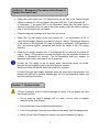
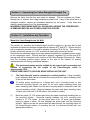
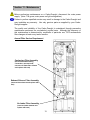
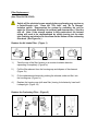
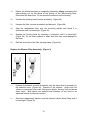
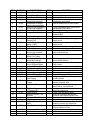
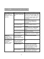
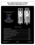
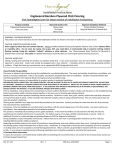
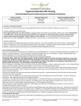
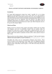
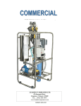
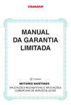
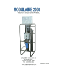
Installation, Operation, and
Service Manual
Carbo-Draught 1000
&
Carbo-Draught Pro
TM
TM
Section 1 Introduction
The Carbo-Draught gas dispense system extracts nitrogen (N2) from ambient air, blends it
with carbon dioxide (CO2) and supplies the blend gas to a draught beer dispense system.
As a component of a properly designed and maintained draught system, the CarboDraught assures brewery quality beverage presentation while it eliminates excessive
foaming and wasted beer.
The Carbo-Draught system uses proven Pressure Swing Adsorption (PSA) technology
with a Carbon Molecular Sieve (CMS) to separate N2 from the atmosphere and store it at
a purity level of at least 99.8%. It uses a precision blender to combine the N2 with CO2
from another storage vessel into two CO2 / N2 blend ratios (commonly 25% / 75% and
60% / 40%). These blends are consistent and accurate to within 2% CO2 of each blend
ratio.
This manual contains the information necessary for the correct use of the Carbo-Draught
1000 and Carbo-Draught Pro units. Should any questions arise regarding safe and
proper installation, operation or maintenance of the Carbo-Draught system, contact the
supplier before proceeding.
Warning: Ensure that all personnel involved in the installation, operation and
maintenance of the Carbo-Draught system, as well as those persons who will act
as supervisory personnel, have read and fully understand the instructions before
attempting to install, operate or perform maintenance on the unit.
2
Section 2 – Contents
Section 1
Introduction
page 2
Section 2
Contents of the Operating Manual
page 3
Section 3
Symbol Definitions
page 4
Section 4
Safety Warning
page 4
Section 5
General Information,
System Schematics
pages 5, 6
Emergency Procedure
in the Event of a Loss in System Pressure
page 7
Section 7
System Leaks
page 7
Section 8
Product Specifications
page 8
Section 9
Unpacking the Carbo-Draught
page 9
Section 10
Installation and Operation of the Carbo-Draught
pages 9 - 12
Section 11
Maintenance
page 13 - 15
Section 12
Parts Identification and Parts List
pages 16, 17
Section 13
Troubleshooting
page 18, 19
Section 14
Service and Parts
page 20
Section 15
P & I Diagram / Electrical Wiring Diagram
page 21
Section 16
Warranty
page 22, 23
Section 6
3
Section 3 – Alert Symbols Used Throughout This Manual
WARNING: The WARNING symbol draws attention to an operating procedure or
practice that can cause injury if it is not observed or performed correctly.
Do not continue past a WARNING symbol until you have fully understood or
satisfied the indicated conditions.
CAUTION: The CAUTION symbol draws attention to an operating procedure or
practice that can damage the unit if it is not observed or performed correctly.
Do not continue past a CAUTION symbol until you have completely understood or
satisfied the indicated conditions.
NOTE: The NOTE symbol draws attention to information that is especially
important to an operating procedure or a practice that is advisable to perform
correctly or observe correctly, but that cannot damage the unit.
Section 4 - Safety Warning
Do not operate the Carbo-Draught until the information contained in this document
has been read and understood by all personnel concerned.
The unit should be connected to an electrical supply in accordance with local
safety regulations. Ensure that the rating plate corresponds to the supply voltage.
Ensure that the unit is grounded.
Nitrogen (N2) & carbon dioxide (CO2) are not poisonous gases but in a
concentrated form present a risk of asphyxiation. The Carbo-Draught produces a
small flow of mixed gases that quickly disperse in the atmosphere. However, do
not directly inhale any gases produced by the unit.
Before service or maintenance is performed on the Carbo-Draught system, the
electrical supply must be switched off and the main electrical lead disconnected.
All personnel handling, using or maintaining the Carbo-Draught must employ safe
working practices and observe all relevant local health and safety regulations.
4
Section 5 - General Information
1.)
CO2 is supplied from a bulk storage vessel. The Carbo-Draught produces N2 by
separating it from the atmosphere using a Carbon Molecular Sieve (CMS). The N2
is stored in a receiver vessel. While producing N2 the unit will depressurize
approximately every 3.5 minutes, resulting in an audible pulse of gas, which
is normal.
Schematic A
Carbo Draught / Carbo-Draught Pro
N2 from storage
1
N2 to storage
B2
To draught system
B1
To soda system
CO2
Back-Up
N2
Back-Up
CO2 Storage
N2 Storage
5
Schematic B
Side of Unit
14
1
2
3
4
5
6
8
7
9
10
11
12
1. CO 2 Inlet (1/4in FPT)
2. N 2 Pressure Gauge
3. N 2 From Storage (1/4in FPT)
4. N 2 To Storage (1/4in FPT)
5. Blend 1 Outlet (1/4in FPT)
6. Blend 2 Outlet (1/4in FPT)
7. Electrical Power Supply Socket
8. Power On / Off Switch
9. Display (Run Time Hrs.)
10. Power On LED (Green)
11. Operating LED (Amber)
12. Service Required LED (Disabled)
13. Fan Slots
14. Data Plate (Includes Serial Number)
13
Carbo-Draught 1000 / Carbo-Draught Pro
2.)
Carbo-Draught units are designed to produce two different mixtures of carbon
dioxide (CO2) and nitrogen (N2) simultaneously at pre-determined ratios.
Blend 1 (typically) = 25% CO2 / 75% N2
Blend 2 (typically) = 60% CO2 / 40% N2
3.)
Carbo-Draught units are classified as non-hazardous for transportation purposes
and non-flammable for fire regulations.
Any interference with the calibration warning labels will invalidate the CarboDraught warranty and may incur costs for re-calibration.
6
Section 6 – Emergency Procedure in the Event of
System Pressure Loss
•
Check the on/off switch (No.8 on Schematic B) on the side of the Carbo-Draught
cabinet to ensure it is ON, and ensure the green LED (No. 10 on Schematic B)
is illuminated. If the green LED is not illuminated, check that the power cord is
securely connected to the unit and to the power supply outlet and that the external
fuse or circuit breaker has not tripped.
•
Check the keg tap couplings to be sure they are secure.
•
Check the CO2 inlet gauge on the unit (location No. 1 on Schematics A & B), to
verify that the supply pressure is at least 60 psig (4.1 barg). If the gauge pressure
is low, switch to the regulated CO2 back-up cylinder (if equipped). With assistance
from your service supplier, determine and correct the cause of low CO2 supply
pressure.
•
Check the N2 supply pressure (No. 2 on Schematic B) to verify that it is above 60
psig (4.1 barg). If the pressure is below this figure, bring the regulated N2 back-up
cylinder (if equipped) into service. Call for assistance from your supplier to
determine and correct the cause of low N2 pressure.
If either the CO2 supply or the N2 supply stops, the blender within the CarboDraught will stop supplying gas to the beer dispense system.
Blend production will resume when gas pressure is restored.
If either of the gas input supply pressures drops but stays above keg pressure, the
blender will continue to produce blended gas, but at a corresponding slower rate
and with less blend accuracy.
Section 7– System Leaks
If a loss of pressure is due to obvious leakage or rupture of a gas supply line, take
the following actions:
•
Do not enter the area of leakage until it is safe to do so (refer to supplier
Material Safety Data Sheets).
•
Ensure the area is well ventilated before entering.
•
Turn off all cylinders if they are accessible and are away from the leakage area.
•
Switch off the Carbo-Draught and contact your service supplier for advice.
7
Section 8 – Product Specifications
•
Model:
Carbo-Draught (Part No. 99001)
Carbo-Draught Pro (Part No. 99002)
•
Dimensions:
Height (incl. mtg. brackets) = 37.4 in (951 mm)
Width = 12.8 in (325 mm)
Depth (incl. mtg. brackets) = 7.4 in (187 mm)
•
Total Weight:
Approx 75 lb (34 kg)
•
Cabinet Materials:
Steel, powder coated white
•
Mounting Hole Spacing:
10 7/16 in (Horizontal) center-to-center
•
Electrical Power Supply:
115 Vac 60 Hz
•
Ambient Temperature:
36 to 950 F (+2 to + 350 C)
•
N2 Storage Vessel Size:
33.5 gal (approx. 127 liters) (Part No. 97001)
•
N2 Production Rate:
Carbo Draught: Approx. 0.035 cfm (1 L / min)
Carbo-Draught Pro: Approx. 0.07 cfm (2 L / min)
•
Nitrogen Purity:
>99.8% (<0.2% oxygen)
•
N2 Storage Generation
Cycle Start Pressure:
94 psig (6.5 barg)
Max N2 Storage (Generation
Cycle Stop) Pressure:
102 psig (7.0 barg)
•
Stored N2 Volume @ Max Press:
30.9 ft3 (approx. 875.6 liters)
•
CO2 Gas Requirement:
90 psig (6.2 barg)
•
Mixed Blends (CO2 / N2):
Two
•
Blend Outlet Pressure:
72.5 psig (5 barg)
•
Inlet and Outlet Bulkhead
Port Size:
1/4” FPT
•
8
Section 9 - Unpacking the Carbo-Draught & Draught Pro
Remove the items from the box and check for damage. The box contains one CarboDraught unit, a manual, and a bag containing a power cord. If any of the items are in a
damaged condition, request an immediate inspection by the carrier. If any items are
missing, please contact your Fizz representative.
WARNING PLEASE MAKE SURE ALL PACKAGING AROUND THE COMPRESSOR
IS REMOVED BEFORE ANY POWER SOURCE IS APPLIED.
Section 10 - Installation and Operation
Mount the Carbo-Draught onto the Wall
The location for mounting the Carbo-Draught should be indoors in an area that is well
ventilated and where the ambient temperature is between 360F and 950F. Ensure that the
wall or supporting member of the wall is capable of bearing 75 lb (34 kg). The mounting
location must have access to a 115V ac electrical supply with a three-pin socket.
Ensure that the electrical supply circuit has adequate capacity for consistent power supply
to the compressor motor. Ensure also that a properly regulated CO2 source and a N2
storage tank will be convenient to the location of the Carbo-Draught (Schematic A). Make
sure the mounting position allows access to the side of the cabinet for making
connections and for viewing operational displays.
The attachment means must be suitable for the type of wall construction and
capable of supporting the full weight of the Carbo-Draught, which is
approximately 75 lb.
PLEASE WEAR SAFETY GOGGLES WHILE INSTALLING THE UNIT.
1.)
The Carbo-Draught must be mounted in a vertical position. Using a (bubble)
level, determine and mark a horizontal line along which the upper mounting holes
of the unit will be located.
To ensure proper anchorage to a framed wall, use a mounting board, or two
horizontal mounting boards; one each for the unit’s upper mounting holes and
lower mounting holes. Make sure that each mounting board is fastened to two wall
support members (studs). (Spacing between the upper and lower mounting holes
on each side of the unit is 36 3/8 inches, from center to center.)
2.)
Mark two points 10 7/16 inches apart along the upper horizontal mounting line on
the mounting surface. Horizontal spacing between the unit’s mounting hole
centers is 10 7/16 inches. At each point drive a No. 10 screw (not provided)
leaving a space of about 1/8 inch between the screw head and the mounting
surface. Make sure that the screw head will pass through the mounting holes on
the Carbo-Draught cabinet. (If mounting the unit to a concrete [block] wall, use
appropriate anchors.)
9
3.)
Match the upper mounting holes on the Carbo-Draught cabinet to the screw heads
and carefully hang the unit. Anchor the bottom of the unit to the mounting surface
with screws. Carefully tighten all mounting screws.
Ensure that there are no electrical devices below the Carbo-Draught unit, as
condensate (water) may drip from the Carbo-Draught unit.
The use of noxious chemicals or machinery that produces fumes is not permitted
within a 20 ft. radius of a Carbo-Draught installation site.
Prepare the Unit for Operation
After the Carbo-Draught unit has been secured to the wall, take off its cover by removing
the (11) screws that hold it in place. Note: Before removing the cover completely,
disconnect the grounding wire located on its inside lower left corner as you face the unit.
Carefully remove the protective foam packing around the compressor. Notice that a
retaining strap is fitted around the compressor for stability during transportation. Locate
this black (hook and loop) strapping under the base of the Carbo-Draught unit, unhook it
and pull the strap out of the unit. Reattach the grounding wire and replace the cover.
Supplies To Have On Hand (Not Supplied With Carbo-Draught Unit):
- Reinforced Beverage Tubing 1/4” ID
- Hose Clamps (Oetiker #13.3) for 1/4” tubing
- Hose Barb Fittings (1/4” x 1/4 NPT)
- Isolation (Ball) Valves (1/4 MPT x 1/4 FPT)
(One recommended in each line to
facilitate pressure tests and to isolate
components for service and switch-over)
- Pressure Gauge,* 0 -160 psig (1/4” CBM)
- Street tee (1/4” NPT)
(For connection of CO2 supply line gauge)
- Hose Barb Tees (1/4”)
(For in-line connection of optional
back-up gas cylinders and for “splitting”
blend gas lines)
- ½” PTFE thread sealant tape
(Fizz P/N 14010)
(Fizz P/N 13001)
(Fizz P/N 13010)
(Fizz P/N 13020)
(Fizz P/N 13100)
(Fizz P/N 13021)
(Fizz P/N 13030)
* Fizz recommends using a pressure gauge at the CO2 inlet port
(No. 1 on Schematic A) to assure that at least 90 psi supply pressure is being
delivered to the unit. CO2 pressure is regulated internally to ensure blend purity.
10
Install External Isolation Valves and N2 Storage and Optional Back-Up Tanks
1.)
Connect the “N2 To Storage” port on the Carbo-Draught cabinet with the inlet port
on the N2 storage tank using ¼” ID beverage tubing, hose barb fittings and
stepless clamps. Installation of an in-line isolation valve is recommended.
The Fizz N2 storage tank is fitted with an isolation valve. Open this valve.
2.)
Connect the outlet port of the N2 storage tank with the “N2 From Storage” port on
the Carbo-Draught cabinet using ¼” ID beverage tubing, hose barb fittings and
stepless clamps. An in-line isolation valve is recommended either at the outlet port
of the N2 storage tank or at the “N2 From Storage” port on the
Carbo-Draught cabinet. (The Fizz N2 storage tank is equipped with this isolation
valve) Close this valve. An optional, regulated back-up N2 cylinder can be
connected in-line using a barbed tee connection. If a back-up cylinder is
connected, its gas supply valve should be turned off.
3.)
Attach isolation valves to the CO2 Inlet port and to the outlet ports for Blend 1 and
Blend 2 on the cabinet. Close these valves. Now the Carbo-Draught is ready to
begin N2 generation for the storage tank.
Note: The Carbo-Draught may take 14 hours to fully pressurize an empty
storage tank. The Carbo-Draught Pro unit will require 6 to 7 hours to fully
pressurize an empty storage tank. To save time, Fizz recommends that the
storage tank be pre-pressurized to 80 - 90 psig using a regulated supply of N2
from a high-pressure cylinder after you arrive at the installation site.
Complete the tank’s pressurization by operating the unit to assure that the
system is performing properly and is ready to be put into service.
Electrical Power-Up
The unit must be connected to a suitable, 115V ac grounded, electric supply
in accordance with local safety regulations. Ensure the rating plate
corresponds to the supply voltage.
Ensure power at the 3-pin (grounded) socket. Using the power cord supplied with
the Carbo-Draught unit, connect the unit to the power supply. Switch the ON/Off
Main Switch to the “ON” position and ensure that the green LED illuminates.
Note: The amber LED also illuminates indicating that the system is in the
charge mode. The fan motor will start immediately and after approximately 120
seconds the on-board compressor will start. The first two cycles of the CarboDraught will be short and no nitrogen will be dispensed. The third and following
cycles will consist of an approximate 1 ½ minute compressor run time alternating
with an exhaust time of about 2 minutes. The Carbo-Draught Pro’s nitrogen
generation process will consist of an approximate 2-minute compressor run time
alternating with an exhaust time of about 1½ minutes. An audible pressure release
will indicate that the unit is producing N2. This audible cycle will continue until the
N2 storage vessel is fully pressurized (to approximately 103 psig).
11
Locate and Connect CO2 and Blended Gas Lines
While the N2 storage tank is being pressurized, determine a connection point to the main
CO2 supply line. (Ensure that the CO2 supply pressure is at least 90 psi.) Determine the
blend gas supply line connection points to the draught beer system. Final connections
and leak testing may cause a brief interruption of service to the beer faucets and should
be accomplished when the establishment is closed or when no beer is being poured.
Make the CO2 and blend gas supply line connections after the N2 storage tank is fully
pressurized to minimize draught system downtime. Try to avoid depressurizing the kegs
in the cooler.
Be sure the gas supply (pressure) from the CO2 storage vessel is turned off or
restricted at the connection point before making the CO2 connection.
1.)
Connect the CO2 inlet port on the Carbo-Draught to the CO2 supply line connection
point using beverage tubing, hose barb fittings and stepless clamps.
2.)
Run the 1/4" ID blend-gas supply lines from the Carbo-Draught to the beer gas
connection points. Connect the lines to the Carbo-Draught’s blend supply ports.
Color-coded or marked supply lines should be used to make sure that Blend 1 (25%
CO2 / 75% N2) and Blend 2 (60% CO2 / 40% N2) are routed to the correct beer types.
3.)
Relieve pressure at the beer-gas connection points. Avoid depressurizing the kegs.
Connect the blend-gas lines to the designated beer gas connection points
4.)
Restore the main CO2 supply pressure.
Open the “CO2 Inlet” valve on
the Carbo-Draught. Open the “N2 From Storage” valve. All isolation valves
except the blend outlet isolation valves should now be open. Observe pressure
gauge(s) and examine all connections for leaks. When the N2 storage tank is fully
pressurized and the N2 pressure gauge remains steady, the Carbo-Draught should
be in the “rest” mode (amber light off) and the compressor will be off. If the N2
pressure falls while the blend outlets are closed this indicates leakage in the
upstream connections or within the Carbo-Draught. Locate and correct the leak(s).
To check for blend-gas leaks, open the isolation valves on the blend-gas outlets.
Ensure that no beer is being dispensed. The N2 pressure gauge may show a small
pressure drop at first but should stabilize. Blend-gas line pressure gauges should be
stable at pressure set by the beer system installer. If pressure continues to drop,
locate and correct the leak(s). Ensure that all beer keg couplings are secure.
The beer-gas system may have leaked before the Carbo-Draught was installed.
Leaking keg tap couplings are common. The leak(s) likely go unnoticed (except
through excessive gas consumption). If that is the case, the Carbo-Draught’s
compressor may run excessively or appear to be unable to keep the N2 storage tank
fully pressurized during off-business hours. Check all gas line connections, including
the keg couplings, for leaks.
12
Section 11 - Maintenance
Before performing maintenance on a Carbo-Draught, disconnect the main power
supply. (Note: The green, main power-on light extinguishes).
Failure to perform specified service may result in damage to the Carbo-Draught and
may invalidate any warranty. Use only genuine parts as supplied by your CarboDraught supplier.
The quality and reliability of the Carbo-Draught is maintained through preventive
maintenance performed on a scheduled, regular basis. Although the frequency of
this maintenance is determined by conditions of particular use, FIZZ recommends
filter changes at least every twelve months.
Annual Filter Service Requirement
Coalescing Filter Assembly
(disconnect bottom tubing
connection, unscrew bowl,
unscrew red foam filter element
and replace with new)
Exhaust Silencer Filter Assembly
(unscrew blue element and replace with
new)
Air Intake Filter Assembly
(unscrew intake element and
replace with new)
13
Filter Replacement
(Use Filter Kit P/N 97002)
Switch off the electrical power supply before performing any service on
a Carbo-Draught unit. Close the “CO2 Inlet” and “N2 To Storage”
isolation valves. Depressurize the system by switching the unit on
again for 20 seconds allowing it to exhaust (and depressurize.) Shut the
unit off. Note: If the storage system is fully pressurized, the internal
tubing will need to be depressurized by slowly turning out the drain
tube retaining nut attached to the elbow on the bottom of the coalescing
filter bowl. (See Figure 2e.)
Replace the Air Intake Filter: (Figure 1)
a
b
c
d
1.)
Twist the cap of the filter housing in a counter-clockwise direction
separating it completely. (Figure 1a)
2.)
Pull the filter element from the housing cap and dispose of the element.
(Figure 1b)
3.)
Fit the replacement element by pushing the element, wide end first, into
the housing cap. (Figure 1c)
4.)
Replace the housing cap (with new filter) turning it clockwise by hand until
it snaps tight. (Figure 1d)
Replace the Coalescing Filter: (Figure 2)
a
b
c
d
e
1.)
Ensure the internal pressure is completely relieved by slowly unscrewing the
tube-retaining nut on the elbow at the bottom of the filter-housing bowl.
Disconnect the drain tube. Do not remove the elbow from the housing.
2.)
Unscrew the housing bowl (counter-clockwise). (Figure 2a)
3.)
Unscrew the filter (counter-clockwise) and discard it. (Figure 2b)
4.)
Align the replacement filter onto the mounting spindle and screw it in
(clockwise) until it is hand-tight. (Figure 2c)
5.)
Replace the housing bowl by screwing it (clockwise) until it is hand-tight.
(Figure 2d) Do not use a wrench or other tools that may cause damage to
the bowl.
6.)
Refit the drain tube to the filter housing elbow. (Figure 2e)
Replace the Silencer Filter Assembly: (Figure 3)
a
b
1.)
Unscrew the silencer (counter-clockwise) from the elbow that is connected to
the solenoid valve. (Figure 3a) Dispose of the silencer. Notice that the
silencer is comprised of an outer, blue porous plastic “housing” with a sintered
brass insert. Both pieces are replaced and therefore do not need to be
separated unless for disposal reasons.
2.)
Screw the replacement silencer onto the solenoid valve’s elbow fitting until it
is hand-tight. (Figure 3b)
15
Section 12 - Parts Identification
http//shop.fizzdog.com
Carbo-Draught 1000 & Carbo-Draught Pro
10
12
6
9
13
15
27
23
8
19
7
22
24
14
2
28
16
17
11
21
26
1
20
5
25
4
3
29
18
16
ITEM
PART NO.
1
97006
Circuit Board (1000)
1
Controls system operation
1
2
3
97101
97102
97007
1
1
1
4
97004
Controls system operation
Turns unit off and on
Brings fresh air into the system for
compressor and cooling
Delivers ambient air to CMS column
5
97210
6
7
97009
97010
Circuit Board (Pro)
Main Power Switch
Cooling Fan assembly
w/mounting hardware
Compressor w/fittings
and mounting hardware
Solenoid Valve Assembly
w/mounting hardware
Gas Blender w/fittings
110 psi Relief Valve
8
9
97029
97011
9
97011
10
11
12
97012
97013
13
97017
14
97015
15
97016
16
17
17
18
19
20
97018
97104
97019
97020
97021
21
97022
22
23
97027
24
25
97023
26
27
28
97024
97025
97002
29
97026
DESCRIPTION
Pressure Gauge
Column Regulator with
Gauge (Pro)
Column Regulator with
gauge (1000)
Check Valve
100mA Fuse
Solenoid Valve Assy
w/mounting hardware
6 mm OD translucent
White Poly Tubing
Coalescing Filter
Assembly w/fittings
Cooling Coil Assy.
6 mm OD Black Nylon
6 mm OD Black Tubing
CMS Column (1000)
CMS Column (Pro)
Cabinet Cover
4 mm OD Black Tubing
6 mm white PTFE Tubing
(with fittings)
10 mm Black Nylon
Tubing
N2 Manifold Block
QTY.
1
1
1
1
1
1
1
1
1
1
ft
1
1
ft
1
1
1
ft
30 in.
ft
1
Bulkhead Connectors
¼” Female NPT
Power Socket
Exhaust Silencer Filter
Element
Air Intake Filter Element
CO2 Regulator
10A Main Power Fuse
250V
Filter Replacement Kit
5
1
Compressor Mounting Kit
17
Manual
1
1
1
1
1
1
2
FUNCTION
Cycles closed and open to pressurize
and exhaust CMS column
Blends N2 and CO2 gases
Protects N2 gas circuit from over
pressurization
Indicates N2 storage tank pressure
Controls release of generated N2 into
supply circuit
Controls release of generated N2 into
supply circuit
Prevents N2 backflow during exhaust
Protects the circuit board
Cycles closed for CMS column faststart at initial start-up
Blender lines
Filters compressed inlet air / drains
accumulated moisture
Cools compressed air before it enters
CMS column
N2 generation and pressure circuit lines
Separates N2 from compressed air
Separates N2 from compressed air
Protects system components
N2 pressure gauge tubing
Compressed air line from compressor
to tube restraint
Connects coalescing filter bowl to
exhaust solenoid valve
Connection for N2 pressure gauge and
switch tubing, and bulkhead
Gas inlet and outlet line and blend
outlet line connection
Power cord attachment point
Quiets air expulsion and diffuses
moisture from coalescing filter bowl
Filters incoming air to compressor
Pre-set to regulate incoming CO2
Protects electrical components of unit.
Quantity includes one spare fuse.
Includes Air Intake Filter, Coalescing
Filter and Silencer Filter
Replaces worn or damaged comp feet
Installation, operation, and service info.
Section 13 - Troubleshooting Guide For Service Agent
Indication
Green LED and
display screen not
illuminated. Unit not
operating.
Possible Cause
Poor power cord
connection / blown power
fuse
Incorrect input voltage
External fuse blown or
circuit breaker tripped
On/Off switch failure
Internal fuse blown
Loose connection or
circuit board failure
Green LED
illuminated but no
operation. Amber
LED not illuminated.
Green LED
illuminated but no
compressor
operation. Amber
LED illuminated.
Unit is in normal rest
mode until storage
pressure drops to 94 psi.
Unit may be in exhaust
mode. Illuminated LED
on exhaust solenoid
indicates exhaust mode.
Compressor failure.
Loose connection or
circuit board failure
18
Corrective Action
Be sure the power cord is securely
connected to the power supply outlet
and to the unit. Check / replace 10A
fuse located in power socket. Check
for voltage at socket, switch, and
circuit board.
Check ‘main’ voltage and rating
number plate for voltage spec.
Check that supply circuits aren’t
overloaded.
Check for voltage at outlet.
Reset circuit breaker; check for
overload.
Verify power to unit. Check voltage
before and after switch. Replace
switch.
Check fuse on printed circuit board.
Replace as necessary.
If voltage checks ok at circuit board,
check for loose connection. Replace
board.
No corrective action necessary
Wait two minutes for compressor to
start.
If compressor fails to start when
compressor cycle starts (LED on
exhaust solenoid goes out) check
voltage to compressor. If voltage
exists, replace compressor.
If no voltage to compressor, check for
loose connections. If board is not
sending voltage, replace board.
N2 storage (tank)
pressure drops
during period of
non-use.
Compressor motor
runs excessively;
unable to reach
maximum N2 storage
pressure
Low blend gas
pressure; beer
pouring slow
Excessive beer
foaming
Internal leak in
Carbo-Draught unit
Leak in N2 storage or
supply line
Close “N2 outlet to storage” valve, run
unit to max pressure, check and
correct compressed air and N2
pressure circuit / fitting leaks.
Leak-check line fittings and
connections. Correct leak(s)
Leak in beer gas circuit or Ensure keg tap couplings are secure.
keg coupling
Check gas line and regulator
connections.
Power off
Check on/off switch and power circuit
Low CO2 inlet (line)
Check CO2 supply (tank) pressure
gauge pressure (below
and contents.
60 psi)
Ensure valves are open.
Out of CO2
Switch to back-up CO2 if equipped.
Have CO2 storage tank refilled.
Low N2 storage pressure If green and amber LED’s are on and
(below 60 psi.)
compressor is cycling, unit may be in
normal recharge mode. Check for
leaks in N2 lines and beer gas lines.
Temperature problem
Check cooler and pour temperatures
Incorrect dispense gas
Check pour rate.
pressure
Check dispense gas pressure at
the keg.
Consult with beer system installer or
beer distributor.
19
Section 14 - Service and Parts
Service and Maintenance
1.) Service or maintenance on the Carbo-Draught 1000 and Carbo-Draught
Pro should be performed only by Fizz trained and authorized professional
service agents who are familiar with gas pressure systems and all
pertinent safety and service procedures.
Fizz recommends the use of Fizz approved replacement parts.
2.) Before calling your service agent or CO2 supplier for service or
troubleshooting assistance, please have the following information:
- Serial number of the Carbo-Draught unit
- Description of the situation
Readings from pressure gauges (CO2 supply, N2 storage, Gas
Blend Supply)
Temperature of cooler and beer at faucet if appropriate.
- Special observations such as excessive beer foaming or continuous
compressor operation.
3.) Fizz recommends that a thorough preventive maintenance check be
performed on the Carbo-Draught 1000 and on the Carbo-Draught Pro
system annually by a qualified professional service agent.
Replacement of the compressor air inlet filter, the coalescing filter,
and the silencer filter assembly should be performed at least every
twelve months or more frequently, depending on environmental
conditions. Filter kit: Fizz P/N 97002.
4.) The Carbo-Draught units have no user serviceable parts. All service work
should be performed by an authorized professional service agent.
Service or modifications performed on the system by unauthorized
persons will void the warranty.
Important Telephone Numbers:
Carbo-Draught System Installer: ___________________________________
Carbo-Draught / CO2 Service Agent: _______________________________
Fizz Dispense Optimization Group: (800) 253 - 6610 [toll free in U.S.]
http//shop.fizzdog.com
20
Section 15- Process & Instrumentation Diagram / Electrical Wiring Diagram
21
Section 16 – Warranty
Warranty Policy
Fizz Dispense Optimization Group, LLC warrants to the Purchaser the CarboDraught system shall be free from any defects in workership and materials for 24
months from the date of shipment from Fizz. Purchaser agrees that as a precondition to any Fizz liability hereunder, Purchaser or its appointed agents shall fully
inspect all goods immediately upon delivery and shall give Fizz written notice of any
claim or purported defect within ten (10) days after discovery of such defect. Use of
the Carbo-Draught system without the recommended inlet air quality (Section 10 of
this manual) or genuine parts will expressly invalidate the warranty.
As a further pre-condition to any Fizz liability hereunder, a Fizz approved service
company must perform parts replacement. Fizz may elect to repair or replace such
equipment or any defective component or part thereof which proves to be defective,
or to refund the purchase price paid by the original Purchaser. Fizz shall not be
liable for defects caused by the effects of normal wear and tear, erosion, corrosion,
fire, explosion, misuse, or unauthorized modification.
Alterations or repair by others than those designated and approved by Fizz or
operation of such equipment in a manner inconsistent with Fizz accepted practices
and all operating instructions, unless pre-authorized in writing by Fizz, shall void this
Warranty.
Fizz’s sole and exclusive liability under this Warranty is to the Purchaser and shall
not exceed the lesser of the cost of repair, cost of replacement, or refund of the net
purchase price paid by the original Purchaser. Any accessories, parts and
equipment supplied by Fizz but not manufactured by Fizz shall carry whatever
warranty the manufacturer has given to Fizz providing it is possible for Fizz to pass
on such warranty to the customer.
Fizz is not liable for any losses (including CO2 or beer), back up gas supply,
damages, or costs of delays, including incidental or consequential damages. These
include lost profits and the cost of the installation or removal of any products or
parts, the installation of replacement products, and any inspection, testing, or
redesign caused by any defect or by the repair or replacement of products arising
from a defect in any product. Fizz specifically makes no warranties or guarantees,
expressed or implied, including the warranties of merchantability or fitness for a
particular purpose or use, other than those warranties expressed herein.
22
WARRANTY CLAIMS PROCEDURE
1.)
All warranty claims must be previously authorized by Fizz Dispense
Optimization Group, LLC. Telephonic / electronic approval may be obtained
by contacting Fizz at:
- Telephone: 800 – 253 - 6610
- Facsimile: 678 – 792 – 7784
or by writing to:
Fizz Dispense Optimization Group, LLC
PO Box 1003
Adairsville GA 30103
USA
2.)
Authorization must be obtained from Fizz prior to shipping any equipment to
Fizz facilities. The model and serial number of the unit must be provided in
order to process the return. If approved, a Return Material Authorization
(RMA) number and proper shipping address will be provided. The RMA
number must be prominently indicated on the packing slip and any packaging
that accompanies the goods being returned. The customer returning the
goods is responsible for all freight, proper packing, and any damage incurred
during shipment of the goods back to Fizz.
23
Copyright: Fizz Dispense Optimization Group, LLC March 2005
dh stock code reference:
24
Fizz Part No. 11707204 Rev. 0, 3-05
17 626 0502