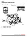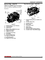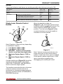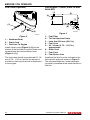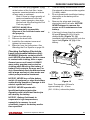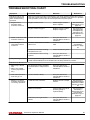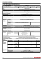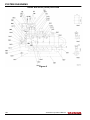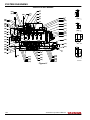
1
JH4
series
OPERATION MANUAL
3JH4E
4JH4AE
4JH4-TE
4JH4-HTE
P/N: 0AJH4–G00103
MARINE
ENGINES
Disclaimers:
All information, illustrations and specifications in this manual are based on the latest
information available at the time of publishing. The illustrations used in this manual are
intended as representative reference views only. Moreover, because of our continuous
product improvement policy, we may modify information, illustrations and / or specifications
to explain and / or exemplify a product, service or maintenance improvement. We reserve
the right to make any change at any time without notice. Yanmar and
are
registered trademarks of Yanmar Co., Ltd. in Japan, the United States and / or other
countries.
All Rights Reserved:
No part of this publication may be reproduced or used in any form by any means - graphic,
electronic, or mechanical, including photocopying, recording, taping, or information storage
and retrieval systems - without the written permission of Yanmar Marine International.
© 2008 Yanmar Marine International
0608
ii
JH4 Series Operation Manual
© 2008 Yanmar Marine International
TABLE OF
CONTENTS
Page
Introduction .............................................................. 1
Record of Ownership .............................................. 2
Safety ....................................................................... 3
Safety Precautions .................................................
General Information .........................................
Before You Operate .........................................
During Operation and Maintenance .....................
4
4
4
4
Location of Safety Decals ........................................ 8
Product Overview ..................................................... 13
Yanmar JH4 Features and Applications ..................... 13
New Engine Break-In ...................................... 13
Component Identification ........................................ 15
Service Side - 3JH4E ...................................... 15
Non-Service Side - 3JH4E ............................... 15
Service Side - 4JH4AE .................................... 16
Non-Service Side - 4JH4AE ............................. 16
Service Side - 4JH4-TE ................................... 17
Non-Service Side - 4JH4-TE ............................. 17
Service Side - 4JH4-HTE ................................. 18
Non-Service Side - 4JH4-HTE .......................... 18
Nameplates ......................................................... 19
Function of Major Components ................................ 20
Control Equipment ................................................ 21
Instrument Panel (Optional) .............................. 21
Single Lever Remote Control Handle .................. 25
Before You Operate .................................................. 27
Diesel Fuel .......................................................... 27
Diesel Fuel Specifications ................................ 27
JH4 Series Operation Manual
© 2008 Yanmar Marine International
iii
TABLE OF CONTENTS
Filling the Fuel Tank ........................................ 31
Bleeding the Fuel System ................................ 32
Engine Oil ........................................................... 33
Engine Oil Specifications ................................. 33
Engine Oil Viscosity ........................................ 34
Checking the Engine Oil .................................. 34
Adding Engine Oil .......................................... 34
Marine Gear or Sail Drive Oil ................................... 35
Marine Gear Oil Specifications .......................... 35
Sail Drive Oil Specifications .............................. 35
Checking Marine Gear Oil ................................ 36
Adding Marine Gear Oil ................................... 36
Checking and Adding Sail Drive Oil .................... 36
Engine Coolant ..................................................... 36
Engine Coolant Specifications ........................... 36
Coolant (Closed Cooling System) ...................... 36
Checking and Adding Coolant ........................... 37
Cranking the Engine .............................................. 40
Engine Operation ...................................................... 41
Starting the Engine ................................................ 43
Before Starting the Engine ............................... 43
To Start the Engine ......................................... 43
If the Engine Fails to Start ................................ 43
Starting at Low Temperatures ........................... 44
After the Engine has Started ............................. 45
Remote Control Handle Operation ............................ 45
Acceleration and Deceleration .......................... 45
Shifting the Engine ......................................... 45
Switching to Trolling (KMH4A only) .................... 46
Cautions During Operation ...................................... 47
Shutting Down the Engine ....................................... 48
Normal Shutdown .......................................... 48
Emergency Shutdown ..................................... 48
Checking the Engine After Operation ......................... 49
Periodic Maintenance ................................................ 51
Safety Precautions ................................................ 51
Precautions ......................................................... 53
The Importance of Periodic Maintenance ............. 53
Performing Periodic Maintenance ...................... 53
The Importance of Daily Checks ........................ 53
Keep a Log of Engine Hours and Daily Checks ..... 53
iv
JH4 Series Operation Manual
© 2008 Yanmar Marine International
TABLE OF CONTENTS
Yanmar Replacement Parts .............................. 53
Tools Required .............................................. 53
Ask Your Authorized Yanmar Marine Dealer or
Distributor for Help ......................................... 53
Tightening Fasteners ...................................... 54
EPA Maintenance Requirements .............................. 55
EPA Requirements for USA and Other Applicable
Countries ..................................................... 55
EPA Requirements ......................................... 55
Conditions to Ensure Compliance with EPA
Emission Standards ........................................ 55
Inspection and Maintenance ............................. 56
Periodic Maintenance Schedule ............................... 57
Inspection and Maintenance of EPA EmissionRelated Parts ................................................ 60
Periodic Maintenance Procedures ............................ 61
Daily Checks ................................................. 61
After Initial 50 Hours of Operation ...................... 62
Every 50 Hours of Operation ............................. 67
Every 250 Hours of Operation ........................... 70
Every 500 Hours of Operation ........................... 77
Every 1000 Hours of Operation ......................... 77
Troubleshooting ....................................................... 79
Troubleshooting After Starting ................................. 79
Troubleshooting Information .................................... 80
Troubleshooting Chart ........................................... 81
Long-Term Storage ................................................... 85
Prepare Engine for Long-Term Storage ...................... 85
Drain Seawater Cooling System ............................... 86
Returning the Engine to Service ............................... 88
Specifications .......................................................... 89
Principal Engine Specifications ................................ 89
3JH4E Engine Specifications ............................ 89
3JH4E Marine Gear Specifications ..................... 91
4JH4AE Engine Specifications .......................... 92
4JH4AE Marine Gear or Sail Drive
Specifications ................................................ 96
4JH4-TE Engine Specifications ......................... 98
4JH4-HTE Engine Specifications ..................... 100
4JH4-TE and 4JH4-HTE Marine Gear or Sail Drive
Specifications .............................................. 102
JH4 Series Operation Manual
© 2008 Yanmar Marine International
v
TABLE OF CONTENTS
System Diagrams ................................................... 103
Piping Diagrams ................................................. 103
Wiring Diagrams ................................................. 130
EPA Warranty USA Only .......................................... 143
Yanmar Co., Ltd. Limited Emission Control System
Warranty - USA Only ...........................................
Your Warranty Rights and Obligations: ..............
Warranty Period: ..........................................
Warranty Coverage: ......................................
Exclusions: .................................................
Owner’s Responsibility: .................................
Customer Assistance: ...................................
143
144
144
145
145
145
146
Emission System Warranty ...................................... 147
Non-Road Emission System Warranty ..................... 147
Yanmar Co., Ltd. Limited Emission Control
System Warranty - USA Only .......................... 147
Maintenance Log ......................................... 150
vi
JH4 Series Operation Manual
© 2008 Yanmar Marine International
INTRODUCTION
Welcome to the world of Yanmar Marine!
Yanmar Marine offers engines, drive
systems and accessories for all types of
boats, from runabouts to sailboats, and from
cruisers to mega yachts. In marine leisure
boating, the worldwide reputation of Yanmar
Marine is second to none. We design our
engines to respect nature. This means
quieter engines, with minimal vibrations,
cleaner than ever. All of our engines meet
applicable regulations, including emissions,
at the time of manufacture.
To help you enjoy your Yanmar JH4 series
engine for many years to come, please
follow these recommendations:
• Read and understand this Operation
Manual before you operate the machine
to ensure that you follow safe operating
practices and maintenance procedures.
• Keep this Operation Manual in a
convenient place for easy access.
• If this Operation Manual is lost or
damaged, order a new one from your
authorized Yanmar Marine dealer or
distributor.
• Make sure this manual is transferred to
subsequent owners. This manual should
be considered a permanent part of the
engine and remain with it.
• Constant efforts are made to improve the
quality and performance of Yanmar
products, so some details included in this
Operation Manual may differ slightly from
your engine. If you have any questions
about these differences, please contact
your authorized Yanmar Marine dealer or
distributor.
• The specifications and components
(instrument panel, fuel tank, etc.)
described in this manual may differ from
ones installed on your vessel. Please refer
to the manual provided by the
manufacturer of these components.
• Refer to the Yanmar Limited Warranty
Handbook for a complete warranty
description.
JH4 Series Operation Manual
© 2008 Yanmar Marine International
1
INTRODUCTION
RECORD OF OWNERSHIP
Take a few moments to record the information you need when you contact Yanmar for
service, parts or literature.
Engine Model:
Engine Serial No.:
Date Purchased:
Dealer:
Dealer Phone:
2
JH4 Series Operation Manual
© 2008 Yanmar Marine International
SAFETY
Yanmar considers safety of great
importance and recommends that anyone
that comes into close contact with its
products, such as those who install,
operate, maintain or service Yanmar
products, exercise care, common sense
and comply with the safety information in
this manual and on the machine’s safety
decals. Keep the labels from becoming dirty
or torn and replace them if they are lost or
damaged. Also, if you need to replace a part
that has a label attached to it, make sure you
order the new part and label at the same
time.
!
This safety alert symbol appears
with most safety statements. It
means attention, become alert,
your safety is involved! Please
read and abide by the message
that follows the safety alert
symbol.
! DANGER
Indicates a hazardous situation which, if
not avoided, will result in death or
serious injury.
! WARNING
Indicates a hazardous situation which, if
not avoided, could result in death or
serious injury.
! CAUTION
Indicates a hazardous situation which, if
not avoided, could result in minor or
moderate injury.
NOTICE
Indicates a situation which can cause
damage to the machine, personal property
and / or the environment or cause the
equipment to operate improperly.
JH4 Series Operation Manual
© 2008 Yanmar Marine International
3
SAFETY
SAFETY PRECAUTIONS
General Information
There is no substitute for common sense
and careful practices. Improper practices or
carelessness can cause burns, cuts,
mutilation, asphyxiation, other bodily injury
or death. This information contains general
safety precautions and guidelines that must
be followed to reduce risk to personal safety.
Special safety precautions are listed in
specific procedures. Read and understand
all of the safety precautions before operation
or performing repairs or maintenance.
During Operation and
Maintenance
! DANGER
The safety message that follows has
DANGER level hazards.
Crush Hazard
NEVER stand under hoisted
engine. If the hoist mechanism
fails, the engine will fall on you.
Before You Operate
! DANGER
The safety messages that follow have
WARNING level hazards.
NEVER permit anyone to
install or operate the
engine without proper
training.
• Read and understand this Operation
Manual before you operate or service the
engine to ensure that you follow safe
operating practices and maintenance
procedures.
• Safety signs and labels are additional
reminders for safe operating and
maintenance techniques.
• See your authorized Yanmar Marine
dealer or distributor for additional training.
4
JH4 Series Operation Manual
© 2008 Yanmar Marine International
SAFETY
Sever Hazard
! WARNING
The safety messages that follow have
WARNING level hazards.
Explosion Hazard
While the engine is running or
the battery is charging,
hydrogen gas is being
produced and can be easily
ignited. Keep the area around
the battery well-ventilated and keep sparks,
open flames and any other form of ignition
out of the area.
Rotating parts can cause
severe injury or death. NEVER
wear jewelry, unbuttoned
cuffs, ties or loose fitting
clothing and ALWAYS tie long
hair back when working near moving /
rotating parts such as the flywheel or PTO
shaft. Keep hands, feet and tools away from
all moving parts.
Alcohol and Drug Hazard
NEVER operate the engine
while under the influence of
alcohol or drugs or feeling ill.
Fire and Explosion Hazard
Diesel fuel is flammable and explosive
under certain conditions.
NEVER use a shop rag to catch the fuel.
Wipe up all spills immediately.
NEVER refuel with the engine running.
Store any containers containing fuel in a
well-ventilated area, away from any
combustibles or sources of ignition.
Fire Hazard
Undersized wiring systems
can cause an electrical fire.
Store any containers containing fuel or other
flammable products in a well-ventilated
area, away from any combustibles or source
of ignition.
Exposure Hazard
ALWAYS wear personal
protective equipment
including appropriate
clothing, gloves, work shoes,
eye and hearing protection as
required by the task at hand.
Entanglement Hazard
NEVER leave the key in the
key switch when you are
servicing the engine.
Someone may accidentally
start the engine and not realize
you are servicing it.
NEVER operate the engine while wearing a
headset to listen to music or radio because
it will be difficult to hear the warning signals.
Store any equipment in a designated area
away from moving parts.
NEVER use the engine compartment for
storage.
JH4 Series Operation Manual
© 2008 Yanmar Marine International
5
SAFETY
! WARNING
! CAUTION
Piercing Hazard
Avoid skin contact with highpressure diesel fuel spray
caused by a fuel system leak
such as a broken fuel injection
line. High-pressure fuel can
penetrate your skin and result in serious
injury. If you are exposed to high-pressure
fuel spray, obtain prompt medical treatment.
NEVER check for a fuel leak with your
hands. ALWAYS use a piece of wood or
cardboard. Have your authorized Yanmar
Marine dealer or distributor repair the
damage.
Burn Hazard
Some of the engine surfaces
become very hot during
operation and shortly after
shut-down. Keep hands and
other body parts away from
hot engine surfaces.
Sudden Movement Hazard
ALWAYS stop the engine before beginning
service.
Exhaust Hazard
The safety messages that follow have
CAUTION level hazards.
Poor Lighting Hazard
Ensure that the work area is adequately
illuminated. ALWAYS install wire cages on
portable safety lamps.
Tool Hazard
ALWAYS use tools appropriate for the task
at hand and use the correct size tool for
loosening or tightening machine parts.
Flying Object Hazard
ALWAYS wear eye protection when
servicing the engine or when using
compressed air or high-pressure water.
Dust, flying debris, compressed air,
pressurized water or steam may injure your
eyes.
Coolant Hazard
Wear eye protection and
rubber gloves when you
handle Long Life engine
coolant. If contact with the
eyes or skin should occur,
flush eyes and wash immediately with clean
water.
NEVER block windows, vents
or other means of ventilation if
the engine is operating in an
enclosed area. All internal
combustion engines create
carbon monoxide gas during operation and
special precautions are required to avoid
carbon monoxide poisoning.
6
JH4 Series Operation Manual
© 2008 Yanmar Marine International
SAFETY
NOTICE
The safety messages that follow have
NOTICE level hazards.
It is important to perform daily checks as
listed in the Operation Manual.
Periodic maintenance prevents unexpected
downtime, reduces the number of accidents
due to poor engine performance and helps
extend the life of the engine.
See your authorized Yanmar Marine dealer
or distributor if you need to operate the
engine at high altitudes. At high altitudes the
engine will lose power, run rough and
produce exhaust gases that exceed the
design specifications.
ALWAYS be environmentally
responsible.
Follow the guidelines of the EPA or other
governmental agencies for the proper
disposal of hazardous materials such as
engine oil, diesel fuel and engine coolant.
Consult the local authorities or reclamation
facility.
NEVER dispose of hazardous materials by
dumping them into a sewer, on the ground
or into ground water or waterways.
If a Yanmar Marine Engine is installed at an
angle that exceeds the specifications stated
in the Yanmar Marine Installation manuals,
engine oil may enter the combustion
chamber causing excessive engine speed,
white exhaust smoke and serious engine
damage. This applies to engines that run
continuously or those that run for short
periods of time.
If you have an installation with two or three
engines and only one engine is operating,
the water pickup (thru-hull) of the nonrunning engine(s) should be closed. This will
prevent water from being forced past the
seawater pump and eventually finding its
way into the engine. The result of water
entering the engine could cause seizure or
other serious problems.
If you have an installation with two or three
engines, and only one engine is operating,
please note that if the propeller shaft thruhull (stuffing box) is lubricated by engine
water pressure and the engines are
interconnected, care must be taken that
water from the running engine does not
enter the exhaust of the non-running engine
(s). This water could cause seizure of the
non-running engine(s). See your authorized
Yanmar Marine dealer or distributor for a
complete explanation of this condition.
If you have an installation with two or three
engines, and only one engine is operating,
it is important to limit the amount of throttle
applied to the running engine. If you observe
black smoke or movement of the throttle
does not increase engine rpm, you are
overloading the engine that is running.
Immediately throttle back to approximately
2/3 throttle or to a setting where the engine
performs normally. Failure to do so may
cause the running engine to overheat or
cause excess carbon buildup which may
shorten the engineʼs life.
JH4 Series Operation Manual
© 2008 Yanmar Marine International
7
SAFETY
LOCATION OF SAFETY DECALS
Figure 1, Figure 2, Figure 3 and Figure 4 show the location of safety decals on Yanmar
JH4 series marine engines.
3JH4E Engines
(2)
(1)
WARNING
(3)
196630-12980
0004550
Figure 1
1 – Part Number: 128377–07350
2 – Part Number: 128377–07260
3 – Part Number: 196630–12980
8
JH4 Series Operation Manual
© 2008 Yanmar Marine International
SAFETY
4JH4AE Engines
(1)
(2)
WARNING
(3)
(4)
0004551
Figure 2
1–
2–
3–
4–
Part Number: 128377–07350
Part Number: 128377–07260
Part Number: 196630–12980
Part Number: 128377–07150
JH4 Series Operation Manual
© 2008 Yanmar Marine International
9
SAFETY
4JH4-TE Engines
(1)
(2)
WARNING
(3)
(4)
128296-07300
0003632
Figure 3
1–
2–
3–
4–
10
Part Number: 128377-07350
Part Number: 128377-07260
Part Number: 196630-12980
Part Number: 128296-07300
JH4 Series Operation Manual
© 2008 Yanmar Marine International
SAFETY
4JH4-HTE Engines
(1)
(3)
(2)
WARNING
128296-07300
(4)
0004552
Figure 4
1–
2–
3–
4–
Part Number: 128377-07350
Part Number: 128377-07260
Part Number: 128296-07300
Part Number: 196630-12980
JH4 Series Operation Manual
© 2008 Yanmar Marine International
11
SAFETY
This Page Intentionally Left Blank
12
JH4 Series Operation Manual
© 2008 Yanmar Marine International
PRODUCT OVERVIEW
YANMAR JH4 FEATURES
AND APPLICATIONS
The JH4 series are four-stroke direct
injection diesel engines equipped with liquid
coolant systems.
The 3JH4E is 3-cylinder and naturally
aspirated.
The 4JH4AE is 4-cylinder and naturally
aspirated.
The 4JH4–TE is 4-cylinder and
turbocharged.
The 4JH4–HTE is 4-cylinder and
turbocharged with an intercooler.
The engines are equipped with a marine
gear or sail drive unit.
These engines are designed for pleasure
craft use.
It is recommended that new vessels be
propped so the engines can operate at 100
- 200 rpm above the fuel stop power rpm to
allow for some added weight and hull
resistance.
Failure to do so can lead to reduced vessel
performance, lead to increased smoke
levels and cause permanent damage to your
engine.
The engine must be installed correctly with
coolant lines, exhaust gas lines and
electrical wiring. Any auxiliary equipment
attached to the engine should be easy to use
and accessible for service. To handle the
drive equipment, propulsion systems
(including the propeller) and other onboard
equipment, always observe the instructions
and cautions given in the operation manuals
supplied by the shipyard and equipment
manufacturers.
The JH4 series engines are designed to be
operated at maximum throttle
(3000 - 3200 rpm) for less than 5% of total
engine time (30 minutes out of every 10
hours) and cruising speed (2800 rpm or
less) for less than 90% of total engine time
(9 hours out of every 10 hours).
The laws of some countries may require hull
and engine inspections, depending on the
use, size and cruising area of the boat. The
installation, fitting and surveying of this
engine all require specialized knowledge
and engineering skills. See Yanmarʼs local
subsidiary in your region or your authorized
Yanmar Marine dealer or distributor.
New Engine Break-In
As with all reciprocating engines, the way
your engine is operated during its first 50
hours of operation plays a very significant
role in determining how long it will last and
how well the engine will perform over its
lifetime.
JH4 Series Operation Manual
© 2008 Yanmar Marine International
13
PRODUCT OVERVIEW
A new Yanmar diesel engine must be
operated at suitable speeds and power
settings during the break-in period to make
the sliding parts, such as piston rings, breakin properly and to stabilize engine
combustion.
Perform this procedure in open waters:
During the break-in period, the engine
coolant temperature gauge should be
monitored, temperature should be between
71˚ and 87˚C (160˚ - 190˚F).
Once past the initial 10 hours until 50 hours,
the engine should be used over its full
operating range, with special emphasis on
running at relatively high power settings.
This is not the time for an extended cruise at
idle or low speed. The boat should be run at
maximum speed minus 400 rpm most of the
time (approximately 70% load), with a 10
minute run at maximum minus 200 rpm
(approximately 80% load) every 30 minutes
and a 4-5 minute period of operation at WOT
(wide open throttle) once each 30 minutes.
During this period, be sure not to operate
your engine at low speed and light load for
more than 30 minutes. If operating engine at
low speed and light load by necessity, just
after the low idle operation, be sure to race
the engine.
During the first 10 hours of operation, the
engine should be run at maximum rpm
minus 400 - 500 rpm (approximately
60 - 70% of load) most of the time. This will
ensure the sliding parts break in properly.
During this period, avoid operating at
maximum engine speed and load to avoid
damaging or scoring sliding parts.
NOTICE: Do not operate at WOT (wide
open throttle) for more than a minute at
a time during the first 10 hours of
operation.
Do not operate the engine at low idle or at
low speed and light load for more than
30 minutes at a time. Since unburned fuel
and engine oil will adhere to the piston rings
when operating at low speeds for long
periods, this will interfere with proper
movement of the rings and the lube oil
consumption may increase. Low idle speed
does not allow break-in of sliding parts.
• With the clutch in NEUTRAL, accelerate
from the low speed position to the high
speed position briefly.
• Repeat this process five times.
To complete engine break-in, perform After
Initial 50 Hours maintenance procedures.
See Periodic Maintenance Schedule on
page 57.
If operating engine at low speed and light
load, you must race the engine to clean the
carbon from the cylinders and fuel injection
valve.
14
JH4 Series Operation Manual
© 2008 Yanmar Marine International
PRODUCT OVERVIEW
COMPONENT
IDENTIFICATION
Non-Service Side - 3JH4E
(2) (1)
Service Side - 3JH4E
(3)
Figure 1 and Figure 2 illustrate a typical
version of a 3JH4E engine. Your engine may
have different equipment from that
illustrated.
(4)
(10)
(9)
(8)
(7)
(11)
(1)
(5)
(10)
(6)
(9)
0004544
Figure 2
(8)
(7)
(6)
(5)
(2)
(4)
(3)
0004543
Figure 1
1 – Intake Silencer (Air Cleaner)
2 – Shift Lever
3 – Marine Gear
4 – Oil Cooler
5 – Engine Oil Filter
6 – Fuel Feed Pump
7 – Engine Oil Filler Cap
8 – Fuel Injection Pump
9 – Fuel Filter
10 – Engine Oil Dipstick
11 – Intake Manifold
1 – Coolant Filler Cap
2 – Engine Nameplate (on rocker arm
cover)
3 – Coolant Pump
4 – Belt Cover
5 – Seawater Pump
6 – Starter Motor
7 – Mixing Elbow
8 – Exhaust Manifold
9 – Alternator
10 – Coolant Tank / Heat Exchanger
JH4 Series Operation Manual
© 2008 Yanmar Marine International
15
PRODUCT OVERVIEW
Service Side - 4JH4AE
Non-Service Side - 4JH4AE
Figure 3 and Figure 4 illustrate a typical
version of a 4JH4AE engine. Your engine
may have different equipment from that
illustrated.
(5)
(6)
(7)
(8)
(1)
(2)
(5)
(6)
(1)
(2)
(7)
(3)
(9)
(8)
(9)
(4)
Figure 4
(10)
(11)
(3)
(4)
(12)
0004545
Figure 3
1 – Air Heater
2 – Intake Silencer
3 – Shift Lever
4 – Marine Gear
5 – Engine Oil Dipstick
6 – Fuel Priming Pump
7 – Fuel Filter
8 – Fuel Injection Pump
9 – Engine Oil Filler Cap
10 – Electric Fuel Feed Pump
11 – Engine Oil Filter
12 – Oil Cooler
16
0004546
1 – Engine Nameplate (on rocker arm
cover)
2 – Coolant Pump
3 – Belt Cover
4 – Seawater Pump
5 – Coolant Filler Cap
6 – Coolant Tank / Heat Exchanger
7 – Exhaust Manifold
8 – Starter Motor
9 – Alternator
JH4 Series Operation Manual
© 2008 Yanmar Marine International
PRODUCT OVERVIEW
Service Side - 4JH4-TE
Non-Service Side - 4JH4-TE
Figure 5 and Figure 6 illustrate a typical
version of a 4JH4-TE engine. Your engine
may have different equipment from that
illustrated.
(12)
(11)
(10)
(9)
(8)
(1)
(2)
(2)
(1)
(9)
(3)
(8)
(4)
(7)
(5)
(6)
0004547
Figure 6
(7)
(6)
(5)
(3)
(4)
0004516
Figure 5
1 – Intake Silencer (Air Cleaner)
2 – Turbocharger
3 – Shift Lever
4 – Marine Gear (KMH4A shown)
5 – Engine Oil Cooler
6 – Engine Oil Filter
7 – Fuel Injection Pump
8 – Fuel Filter
9 – Fuel Priming Pump
10 – Engine Oil Dipstick
11 – Intake Manifold
12 – Engine Oil Filler Cap
1 – Engine Nameplate (on rocker arm
cover)
2 – Coolant Filler Cap
3 – Coolant Pump
4 – Belt Cover
5 – Seawater Pump
6 – Alternator
7 – Starter Motor
8 – Exhaust / Water Mixing Elbow
9 – Coolant Tank / Heat Exchanger
JH4 Series Operation Manual
© 2008 Yanmar Marine International
17
PRODUCT OVERVIEW
Service Side - 4JH4-HTE
Non-Service Side - 4JH4-HTE
Figure 7 and Figure 8 illustrate a typical
version of a 4JH4–HTE engine. Your engine
may have different equipment from that
illustrated.
(12)
(2)
(2)
(10)
(1)
(3)
(9)
(11)
(1)
(10)
(9)
(4)
(8)
(6)
(5)
(7)
(8)
0004549
Figure 8
(7)
(3)
(5)
(4)
0004548
Figure 7
1 – Intake Silencer
2 – Turbocharger
3 – Shift Lever (KMH4A)
4 – Marine Gear (KMH4A)
5 – Engine Oil Cooler
6 – Engine Oil Filter
7 – Fuel Injection Pump
8 – Fuel Filter
9 – Fuel Priming Pump
10 – Engine Oil Dipstick
11 – Intake Manifold
12 – Engine Oil Filler Cap
18
(6)
1 – Engine Nameplate (on rocker arm
cover)
2 – Coolant Filler Cap
3 – Coolant Pump
4 – Belt Cover
5 – Seawater Pump
6 – Alternator
7 – Intercooler
8 – Starter Motor
9 – Exhaust Mixing Elbow
10 – Coolant Tank / Heat Exchanger
JH4 Series Operation Manual
© 2008 Yanmar Marine International
PRODUCT OVERVIEW
NAMEPLATES
The nameplates of Yanmar JH4 series
engines are shown in Figure 9. Check the
engineʼs model, output, rpm and serial
number on the nameplate. Please replace if
damaged or lost.
The engine nameplate is attached to the
engine rocker arm cover.
The marine gear nameplate (Figure 10) is
attached to the marine gear. Check the
marine gearʼs model, gear ratio, oil used, oil
quantity and serial number
MODE L
GEAR R ATIO
OIL
OIL QT Y.
NO.
KM
SAE
20 / 30 HD
LTR.
Model
0004529
Gear Model
/
Continuous power kW
Speed of prop,shaf t
/
Fuel stop power kW
Figure 10
min-1
min-1
min
-1
ENG.No.
The sail drive nameplate (Figure 11) is
attached to the sail drive. Check the sail
drive model and serial number.
MODEL
PASSED
MARK
0004574
MFG.NO.
Figure 9
MADE IN JAPAN
0004575
Figure 11
JH4 Series Operation Manual
© 2008 Yanmar Marine International
19
PRODUCT OVERVIEW
FUNCTION OF MAJOR COMPONENTS
Name of Component
Function
Fuel Filter
Removes dirt and water from the fuel. Drain the filter periodically. The filter element
should be replaced periodically. The water separator (if equipped) should be
drained periodically. See Draining Fuel Filter / Water Separator on page 67.
Fuel Feed Pump
Pumps fuel from the tank to the fuel injection system.
Fuel Priming Pump (if
equipped)
This is a manual fuel pump. Pushing the knob on the top of the fuel filter feeds the
fuel. The pump is also used to bleed air from the fuel system.
Engine Oil Filler Port
Filler port for engine oil.
Engine Oil Filter
Filters fine metal fragments and carbon from the engine oil. Filtered engine oil is
distributed to the engine’s moving parts. The filter is a cartridge type and the
element should be replaced periodically. See Changing the Engine Oil and
Replacing the Engine Oil Filter Element on page 72.
Marine Gear Filler Port
Filler port for marine gear lube oil. Located on top of the marine gear case.
Cooling System
There are two cooling systems: closed cooling with coolant (freshwater) and
seawater. The engine is cooled by the closed cooling circuit. The closed circuit is
cooled by seawater using a heat exchanger. The seawater also cools the
engine / marine gear oil and intake air (depending on model) through the cooler(s)
in an open circuit.
Closed Cooling
Circulation Pump
The centrifugal water pump circulates coolant inside the engine. The circulating
pump is driven by a V-belt.
Seawater Pump
Pumps seawater from outside vessel to the engine. The seawater pump is geardriven and has a replaceable rubber impeller. Do not operate it without seawater,
as this will damage the impeller.
Coolant Filler Cap
When the coolant temperature rises, the pressure inside the coolant tank increases
and opens the pressure valve in the filler cap. When the pressure valve in the filler
cap is opened, hot water and steam pass through a rubber hose to the coolant
recovery tank. When the engine cools and the pressure inside the coolant recovery
tank drops, the vacuum valve in the filler cap opens and the coolant in the coolant
recovery tank returns to the water tank through the pipe and filler cap. This
minimizes coolant consumption.
Coolant Recovery Tank
The pressure valve in the filler cap releases vapor and hot water overflow to the
coolant recovery tank. When the engine stops and the coolant cools, the pressure
in the coolant tank drops. The filler cap vacuum valve then opens to send water
back from the coolant recovery tank. This minimizes coolant consumptions. The
closed cooling system coolant level can easily be checked and refilled in this tank.
Oil Cooler - Engine
A heat exchanger that cools high temperature engine oil using coolant.
Oil Cooler - Marine Gear
(Optional)
This heat exchanger that cools the marine gear (KMH4A) oil using seawater.
Turbocharger (if
equipped)
The turbocharger pressurizes the air coming into the engine. It is driven by a turbine
that is energized by exhaust gases.
Intercooler (if equipped)
This heat exchanger cools the pressurized charging air from the turbocharger with
seawater to increase the charging air quantity.
Intake Silencer (Air
Cleaner)
The intake silencer guards against dirt in the air and reduces the noise of air intake.
Nameplates
Nameplates are provided on the engine and the marine gear and have the model,
serial number and other data.
Starter
Starter motor for the engine. Powered by the battery.
Alternator
Driven by belt and generates electricity and charges the battery.
Engine Oil Dipstick
Gauge stick for checking the engine oil level.
20
JH4 Series Operation Manual
© 2008 Yanmar Marine International
PRODUCT OVERVIEW
CONTROL EQUIPMENT
The equipment in the control room makes remote control operation possible. It consists of
the instrument panel, which is connected to the engine by a wire harness, and the remote
control handle, which is connected by control cables to the engine control lever and marine
gear.
Instrument Panel (Optional)
Equipment and Functions
The instrument panel is located in the cockpit. The following instruments enable you to start
or stop the engine and to monitor its condition during operation.
B-Type
(9)
(8)
(7)
(6)
(1)
(5)
(2)
(4)
(3)
0004486
1–
2–
3–
4–
5–
Tachometer
Hourmeter
Moisture Cap for Key Switch
Key Switch
Stop Button
Figure 12
6 – Battery Low Charge Indicator
7 – Water in Sail Drive Seal Indicator
8 – Engine Oil Low Pressure Indicator
9 – Coolant High Temperature Indicator
JH4 Series Operation Manual
© 2008 Yanmar Marine International
21
PRODUCT OVERVIEW
C-Type
(13)
(12)
(11)
(1)
(10)
(2)
(9)
(3)
(4)
(8)
(7)
(5)
1–
2–
3–
4–
5–
6–
7–
22
(6)
0004503
Figure 13
Coolant High Temperature Indicator 8 – Key Switch
Coolant Temperature Gauge
9 – Stop Button
Engine Oil Low Pressure Indicator 10 – Battery Low Charge Indicator
Engine Oil Pressure Gauge
11 – Water in Sail Drive Seal Indicator
Tachometer
12 – Water in Fuel Filter Indicator (if
equipped)
Hourmeter
13 – Not Used on This Engine
Moisture Cap for Key Switch
JH4 Series Operation Manual
© 2008 Yanmar Marine International
PRODUCT OVERVIEW
Meters
B-Type and C-Type panels use analog electric gauges with needle indicators.
Instrument
Function
Tachometer
Shows engine rotation speed.
Hourmeter
Shows number of operating hours. Can be used as a guide for
periodic maintenance checks. The hourmeter is located at the
bottom of the tachometer.
Coolant Temperature Gauge (C-Type only)
Shows the coolant temperature.
Engine Oil Pressure Gauge (C-Type only)
Shows the engine oil pressure.
Panel Lights
When turning the key switch to ON, the gauges will illuminate for
easier viewing.
Key Switch
(1)
The ON position (Figure 14, (3)) allows
electrical current to the controls and
equipment and allows the engine to keep
running. To stop the engine, keep the key
switch in the ON position and push the stop
button. After stopping the engine, turn key to
OFF position.
(2)
(3)
(4)
0003622
Figure 14
The GLOW position (Figure 14, (1)) is the
start aid position. Electric current to the glow
plug or air heater (if equipped) is turned on.
The air heaters is standard on the 4JH4AE
and optional on the 3JH4E, 4JH4–TE and
4JH4–HTE models. When the key is
released, the switch will automatically move
to the ON position.
The START position (Figure 14, (4)) allows
current to the starting motor. When starting
the engine, move the key to the START
position and release. The key will
automatically move to the ON position.
When the key is in the OFF position
(Figure 14, (2)) the electric current is off.
The key can be inserted or removed in this
position.
JH4 Series Operation Manual
© 2008 Yanmar Marine International
23
PRODUCT OVERVIEW
Indicators and Alarms (Optional)
When a sensor detects a problem during
operation, the indicator on the instrument
panel will light and an alarm will sound.
Indicators are located on the instrument
panel, the alarm is located on the back of the
panel. Under normal operating conditions,
the indicators are off.
Figure 18
Water in Sail Drive Seal Indicator and Alarm
(Figure 18) - When water is detected
between the seals of the sail drive, the
indicator will light and the alarm will sound.
Figure 15
Battery Low Charge Indicator
(Figure 15) - When the alternator output is
too low, the indicator will light. When
charging begins, the indicator will turn off.
No alarm will sound for low battery charge.
Figure 16
Coolant High Temperature Indicator and
Alarm (Figure 16) - When coolant
temperature reaches the maximum
allowable temperature (95˚C [203˚F] or
higher), the indicator will light and the alarm
will sound. Continuing operation at
temperatures exceeding the maximum limit
will result in damage and seizure. Check the
load and troubleshoot the cooling system.
Figure 19
Water in Fuel Filter Indicator and Alarm (CType only) - 4JH4-TE and 4JH4–HTE
engines only - (Figure 19) - When the water
level in the fuel filter / water separator
becomes too high, the indicator will light and
the alarm will sound. Drain the water from
the fuel filter / water separator. See Draining
Fuel Filter / Water Separator on page 67.
Figure 17
Engine Oil Low Pressure Indicator and
Alarm (Figure 17) - When the engine oil
pressure falls below normal, the oil pressure
sensor will send a signal to the indicator
causing it to light and the alarm to sound.
Stop operation immediately to avoid
damage to the engine. Check the oil level
and troubleshoot the lubrication system.
24
JH4 Series Operation Manual
© 2008 Yanmar Marine International
PRODUCT OVERVIEW
Alarms
Check that indicators and alarms are working normally when the key is turned to ON.
Key Switch
OFF ⇒ ON
START ⇒ ON
Engine
Before start
Running
Alarm
Sound
Stop
Battery Low Charge Indicator
ON
OFF
Coolant High Temperature Indicator
OFF
OFF
Engine Oil Low Pressure Indicator
ON
OFF
Water in Sail Drive Seal Indicator (if equipped)
OFF
OFF
Indicators
Single Lever Remote Control
Handle
(3)
(2)
(5)
(1)
(4)
When the handle is pulled out
(Figure 21, (1)), the engine speed can be
controlled without engaging the clutch. The
clutch remains in NEUTRAL, no load
position. Turn the knob (Figure 21, (2))
counterclockwise to move the handle or
clockwise to lock the handle.
(2)
0004504
Figure 20
Note: Direction of travel will vary depending
on installation location.
1 – Low Speed - FWD or REV
2 – Low Speed - FWD or REV
3 – NEUTRAL - Power to the propeller
shaft is cut off and the engine idles
4 – Maximum Engine Speed - FWD or
REV
5 – Maximum Engine Speed - FWD or
REV
A single handle-type (Figure 20) should be
used to operate the marine gear clutch
(NEUTRAL, FORWARD, and REVERSE)
and to control the engine speed.
(1)
0004511
Figure 21
Note: Yanmar recommends the use of a
single-lever type for the remote control
system. If only a two-lever type is available
in the market, reduce engine rpm to 1000
rpm or less before engaging and
disengaging the marine gear clutch.
The handle controls the direction of the boat
(ahead or astern) and also acts as an
accelerator by increasing engine speed as
the lever is pushed further in FORWARD or
REVERSE directions.
JH4 Series Operation Manual
© 2008 Yanmar Marine International
25
PRODUCT OVERVIEW
This Page Intentionally Left Blank
26
JH4 Series Operation Manual
© 2008 Yanmar Marine International
BEFORE YOU OPERATE
This section of the Operation Manual
describes the diesel fuel, engine oil, and
engine coolant specifications and how to
replenish them. It also describes the daily
engine checks.
Before performing any operations within this
section, review the Safety section on page
3.
DIESEL FUEL
Diesel Fuel Specifications
DANGER!
Diesel fuel is flammable and explosive
under certain conditions. Refer to Fire
and Explosion Hazard on page 5.
NOTICE: Only use diesel fuels
recommended by Yanmar for the best
engine performance, to prevent engine
damage and to comply with EPA
warranty requirements. Only use clean
diesel fuel.
Diesel fuel should comply with the following
specifications. The table lists several
worldwide specifications for diesel fuels.
DIESEL FUEL
SPECIFICATION
LOCATION
No. 2-D, No. 1-D, ASTM
D975
USA
EN590:96
European Union
ISO 8217 DMX
International
BS 2869-A1 or A2
United Kingdom
JIS K2204 Grade No. 2
Japan
JH4 Series Operation Manual
© 2008 Yanmar Marine International
27
BEFORE YOU OPERATE
Bio-Diesel Fuels
Yanmar approves the use of biodiesel fuels
that do not exceed a blend of 5% nonmineral oil based fuel with 95% standard
diesel fuel. Such biodiesel fuels are known
in the marketplace as B5 biodiesel fuels. B5
biodiesel fuel can reduce particulate matter
and the emission of “greenhouse” gases
compared to standard diesel fuel.
CAUTION! If the B5 biodiesel fuel used
does not meet the approved
specifications, it will cause abnormal
wear of injectors, reduce the life of the
engine and it may affect the warranty
coverage of your engine.
B5 diesel fuels must meet certain
specifications
The biodiesel fuels must meet the minimum
specifications for the country in which they
are used:
• In Europe, biodiesel fuels must comply
with the European Standard EN14214.
• In the United States, biodiesel fuels must
comply with the American Standard
ASTM D-6751.
Biodiesel should be purchased only from
recognized and authorized diesel fuel
suppliers.
28
Precautions and concerns regarding
the use of bio-fuels:
• Biodiesel fuels have a higher content of
methyl-esters, which may deteriorate
certain metal, rubber and plastic
components of the fuel system. The
customer and / or boat builder are
responsible to verify the usage of
biodiesel compatible components on the
vessel fuel supply and return systems.
• Free water in biodiesel may result in
plugging of fuel filters and increased
bacterial growth.
• High viscosity at low temperatures may
result in fuel delivery problems, injection
pump seizures, and poor injection nozzle
spray atomization.
• Biodiesel may have adverse effects on
some elastomers (seal materials) and
may result in fuel leakage and dilution of
the engine lubricating oil.
• Even biodiesel fuels that comply with a
suitable standard as delivered, will
require additional care and attention to
maintain the quality of the fuel in the
equipment or other fuel tanks. It is
important to maintain a supply of clean,
fresh fuel. Regular flushing of the fuel
system, and / or fuel storage containers,
may be necessary.
• The use of biodiesel fuels that do not
comply with the standards as agreed to by
the diesel engine manufacturers and the
diesel fuel injection equipment
manufacturers, or biodiesel fuels that
have degraded as per the precautions
and concerns above, may affect the
warranty coverage of your engine.
JH4 Series Operation Manual
© 2008 Yanmar Marine International
BEFORE YOU OPERATE
Additional Technical Fuel
Requirements
Handling of Diesel Fuel
• The fuel cetane number should be equal
to 45 or higher.
• The sulfur content must not exceed 0.5%
by volume. Less than 0.05% is preferred.
• NEVER mix kerosene, used engine oil, or
residual fuels with the diesel fuel.
• Water and sediment in the fuel should not
exceed 0.05% by volume.
• Keep the fuel tank and fuel-handling
equipment clean at all times.
• Ash content not to exceed 0.01% by
volume.
• Carbon residue content not to exceed
0.35% by volume. Less than 0.1% is
preferred.
• Total aromatics content should not
exceed 35% by volume. Less than 30% is
preferred.
• PAH (polycyclic aromatic hydrocarbons)
content should be below 10% by volume.
• Do not use Biocide.
• Do not use kerosene or residual fuels.
1.
Water and dust in the fuel may cause
engine failure. When fuel is stored, be
sure that the inside of the storage
container is clean and dry, and that the
fuel is stored away from dirt or rain.
0004512
2.
Figure 1
Keep the fuel container stationary for
several hours to allow any dirt or water
to settle to the bottom of the container.
Use a pump to extract the clear, filtered
fuel from the top of the container.
JH4 Series Operation Manual
© 2008 Yanmar Marine International
29
BEFORE YOU OPERATE
Fuel Tank (Optional)
Fuel System - 3JH4E, 4JH4-TE and
4JH4-HTE
(1)
(8)
(2)
(7)
(3)
(3)
(4)
(1)
(2)
0004542
Figure 2
1 – Sediment Bowl
2 – Drain Cock
3 – Fuel Line To Engine
Install a drain cock (Figure 2, (2)) at the
bottom of the fuel tank to remove water and
contaminants from the sediment bowl
(Figure 2, (1)).
The fuel outlet should be positioned 20 - 30
mm (0.75 - 1.125 in.) above the bottom of
the tank so that only clean fuel is distributed
to the engine.
30
Figure 3
(5)
(6)
0004489
1–
2–
3–
4–
5–
Fuel Filter
To Fuel Injection Pump
Less than 500 mm (20.0 in.)
Fuel Cock
20 - 30 mm (0.75 - 1.125 in.)
approximate
6 – Drain Cock
7 – Fuel Tank
8 – Fuel Return Line
Install the fuel line from the fuel tank to the
fuel injection pump as shown in Figure 3.
The recommended fuel / water separator
(optional) is installed at the center section of
that line.
JH4 Series Operation Manual
© 2008 Yanmar Marine International
BEFORE YOU OPERATE
Fuel System - 4JH4AE
(5)
4.
(7)
5.
(6)
(1)
(4)
Stop fueling when the gauge shows the
fuel tank is full. NOTICE: NEVER
overfill the fuel tank.
Replace the fuel cap and hand-tighten.
Over-tightening the fuel cap will
damage it.
(10)
(9)
(2)
(3)
(8)
0004553
Figure 4
1–
2–
3–
4–
5–
6–
7–
8–
9–
Fuel Tank
Fuel Cock
Water Separator
Fuel Feed Pump
Fuel Filter
To Fuel Injection Pump
Fuel Return Line
Drain Cock
20 - 30 mm (0.75 - 1.25 in.)
approximate
10 – Less than 400 mm (16.38 in.)
Filling the Fuel Tank
Before filling fuel tank for the first
time:
DANGER!
NEVER refuel with the engine running.
Refer to Fire and Explosion Hazard on
page 5.
1.
Rinse fuel tank with kerosene or diesel
fuel. Dispose of waste properly.
To fill the fuel tank:
1.
2.
3.
Clean the area around the fuel cap.
Remove the fuel cap from the fuel tank.
Fill the tank with clean fuel free of oil and
dirt. NOTICE: Hold the hose nozzle
firmly against the filler port while
filling. This prevents static
electricity buildup which could
cause sparks and ignite fuel vapors.
JH4 Series Operation Manual
© 2008 Yanmar Marine International
31
BEFORE YOU OPERATE
Bleeding the Fuel System
1.
The fuel system has an automatic air
bleeding device that purges air from the fuel
system. No manual air bleeding is required
for normal operation. Bleeding must be
done if any fuel system maintenance has
been performed (replacement of fuel filter,
etc.) or if the engine does not start after
several attempts.
2.
3.
4.
5.
Bleeding the Fuel System - 3JH4E
6.
Check the fuel level in the fuel tank.
Refill if necessary.
Open the fuel cock of the fuel tank.
Loosen the air bleed screw
(Figure 5, (2)) 2 - 3 turns.
Push up and down on the priming pump
(Figure 5, (1)) to release air out of the
air bleed screw.
Continue pumping until a solid stream
of fuel with no air bubbles begins to
flow.
Tighten the air bleed screw.
Note: After engine start-up, the automatic
air-bleeding device works to purge the air in
the fuel system.
(2)
Bleeding the Fuel System - 4JH4AE
(3)
(1)
(4)
(2)
(3)
(1)
(4)
(5)
(5)
(6)
0004555
Figure 6
(6)
Figure 5
1–
2–
3–
4–
5–
6–
32
Fuel Injector
Air Bleed Screw
To Fuel Tank
Fuel Filter
Fuel Injection Pump
Fuel Feed Pump
0004554
1–
2–
3–
4–
5–
6–
Fuel Injector
Fuel Filter
Priming Pump
Air Bleed Screw
Fuel Feed Pump
Fuel Injection Pump
1.
Check the fuel level in the fuel tank.
Refill if necessary.
Open the fuel cock of the fuel tank.
Loosen the air bleed screw
(Figure 6, (4)) 2 - 3 turns.
2.
3.
JH4 Series Operation Manual
© 2008 Yanmar Marine International
BEFORE YOU OPERATE
4.
5.
6.
Push up and down on the priming pump
(Figure 6, (3)) to release air out of the
air bleed screw.
Continue pumping until a solid stream
of fuel with no air bubbles begins to
flow.
Tighten the air bleed screw.
Bleeding the Fuel System - 4JH4-TE
and 4JH4-HTE
(1)
(2)
(3)
(4)
0004494
Figure 7
1–
2–
3–
4–
Priming Pump
Air Bleed Screw
From Fuel Tank
To Fuel Injection Pump
1.
Check the fuel level in the fuel tank.
Refill if necessary.
Open the fuel cock of the fuel tank.
Loosen the air bleed screw
(Figure 7, (2)) 2 - 3 turns.
Push up and down on the priming pump
(Figure 7, (1)) to release air out of the
air bleed screw.
Continue pumping until a solid stream
of fuel with no air bubbles begins to
flow.
Tighten the air bleed screw.
2.
3.
4.
5.
6.
ENGINE OIL
Engine Oil Specifications
NOTICE: Using engine oil that does not
meet or exceed the following guidelines
or specifications may cause seizure of
parts, abnormal wear and shorten
engine life.
Service Categories
Use an engine oil that meets or exceeds the
following guidelines and classifications:
• 3JH4E, 4JH4-TE and 4JH4-HTE: API
Service Categories CD or higher.
• 4JH4AE: API Service Category CH-4 or
higher.
• SAE Viscosity: 10W30, 15W40. Engine
oil 10W30 and 15W40 can be used
throughout the year.
NOTICE:
• Be sure the engine oil, engine oil
storage containers, and engine oil
filling equipment are free of sediment
or water.
• Change the engine oil after the first 50
hours of operation and then at every
250 hours thereafter.
• Select the oil viscosity based on the
ambient temperature where the
engine is being operated. See the SAE
Service Grade Viscosity Chart
(Figure 8).
• Yanmar does not recommend the use
of engine oil “additives.”
NOTICE: NEVER use an engine starting
aid such as ether. Engine damage will
result.
JH4 Series Operation Manual
© 2008 Yanmar Marine International
33
BEFORE YOU OPERATE
Checking the Engine Oil
(1)
(2)
SAE 10W-30
SAE 15W-40
(3)
(4)
(5)
-4°F 14°F 32°F 50°F 68°F 86°F 104°F
(-20°C) (-10°C) (0°C) (10°C) (20°C) (30°C) (40°C)
0000005
Figure 8
Handling Engine Oil
1.
2.
3.
When handling and storing engine oil,
be careful not to allow dust and water to
contaminate the oil. Clean around the
filler port before filling.
Do not mix lube oils of different types or
brands. Mixing may cause the chemical
characteristics of the oil to change and
lubricating performance to decrease,
reducing the engine’s life.
Engine oil should be replaced at the
specified intervals, regardless if the
engine has been operated.
Figure 9
Note: 4JH4-TE shown. Other models are
similar.
1.
2.
3.
4.
Engine Oil Viscosity
5.
SAE 10W30 or SAE15W40 are the
recommended oil viscosities.
6.
If you operate your equipment at
temperatures outside the limits shown,
consult your authorized Yanmar dealer or
distributor for special lubricants or starting
aids.
Make sure the engine is level.
Remove dipstick (Figure 9, (3)) and
wipe with clean cloth.
Fully reinsert dipstick.
Remove dipstick. The oil level should
be between upper (Figure 9, (4)) and
lower (Figure 9, (5)) lines on the
dipstick.
Add oil if necessary. See Adding
Engine Oil on page 34.
Fully reinsert dipstick.
Adding Engine Oil
1.
2.
3.
34
0004490
NOTICE: Prevent dirt and debris
from contaminating engine oil.
Carefully clean the dipstick and the
surrounding area before you
remove the cap. Remove the yellow
oil filler port cap from filler port
(Figure 9, (1)) and fill with engine oil.
Fill with oil to the upper limit
(Figure 9, (4)) on the dipstick
(Figure 9, (3)). NOTICE: NEVER
overfill the engine with engine oil.
Insert the dipstick fully to check the
level. NOTICE: ALWAYS keep the oil
level between upper and lower lines
on the oil cap / dipstick.
JH4 Series Operation Manual
© 2008 Yanmar Marine International
BEFORE YOU OPERATE
4.
Hand-tighten the filler port cap
securely.
MARINE GEAR OR SAIL
DRIVE OIL
Marine Gear Oil Specifications
Use marine gear oil that meets or exceeds
the following guidelines and classifications:
KM35P, KM35A, KM35A2, KM4A1,
KM4A2, KMH4A:
• API Service Categories CD or higher
• SAE Viscosity #20 or #30
ZF30M, ZF25A:
• ATF (Automatic Transmission Fluid)
Sail Drive Oil Specifications
Refer to the operation manual of the sail
drive for the procedure to fill or replace the
sail drive oil.
3JH4E, 4JH4AE (SD40, SD50 / 50-4T):
• SAE Viscosity #90 or 80W90
• QuickSilver® 1 High Performance Gear
Lube
4JH4-TE (SD40, SD50 / 50-4T):
• Only use QuickSilver® High Performance
Gear Lube.
1
QuickSilver is a registered trademark of Brunswick ® Corporation.
JH4 Series Operation Manual
© 2008 Yanmar Marine International
35
BEFORE YOU OPERATE
Checking Marine Gear Oil
(1)
(2)
(3)
(4)
ENGINE COOLANT
Engine Coolant Specifications
Note: In the U.S., LLC is required for the
warranty to be valid.
• Texaco Long Life Coolant (LLC), both
standard and premixed, product code
7997 and 7998
• Havoline Extended Life
Antifreeze / Coolant, product code 7994
0004491
Figure 10
Note: 4JH4-TE with KMH4A marine gear
shown.
1.
2.
3.
4.
5.
6.
Make sure engine is level.
Remove the filler cap (Figure 10, (1))
at the top of the housing.
Remove dipstick (Figure 10, (2)) and
wipe with clean cloth.
Fully reinsert dipstick.
Remove dipstick. The oil level should
be between upper (Figure 10, (3)) and
lower (Figure 10, (4)) lines on the
dipstick.
Fully reinsert dipstick.
Adding Marine Gear Oil
1.
2.
3.
4.
5.
Make sure the engine is level.
Remove the filler cap at the top of the
housing (Figure 10, (1)).
Fill with oil to the upper limit on the
dipstick (Figure 10, (3)). See Marine
Gear Oil Specifications on page 35.
NOTICE: NEVER overfill the marine
gear with oil.
Fully reinsert dipstick.
Tighten the filler port cap by hand.
Checking and Adding Sail Drive
Oil
Refer to the operation manual for SD50-T for
the procedure to check and fill the sail drive
oil.
36
NOTICE: Following the manufacturer’s
recommendations, use a proper LLC
which will not have any adverse effects
on the materials (cast iron, aluminum,
copper, etc.) of the engine’s cooling
system. See Engine Coolant
Specifications on page 33.
ALWAYS use the mixing ratios specified by
the antifreeze manufacturer for the
temperature range.
Coolant (Closed Cooling System)
NOTICE: ALWAYS add LLC to soft water
– especially when operating in cold
weather. NEVER use hard water. Water
should be clean and free from sludge or
particles. Without LLC, cooling
performance will decrease due to scale
and rust in the coolant system. Water
alone may freeze and form ice; it
expands approximately 9% in volume.
Use the proper amount of coolant
concentrate for the ambient
temperature as specified by the LLC
manufacturer. LLC concentration
should be a minimum of 30% to a
maximum of 60%. Too much LLC will
decrease the cooling efficiency.
Excessive use of antifreeze also lowers
the cooling efficiency of the engine.
NEVER mix different types or brands of
LLC, as a harmful sludge may form.
Mixing different brands of antifreeze
may cause chemical reactions, and may
make the antifreeze useless or cause
engine problems.
JH4 Series Operation Manual
© 2008 Yanmar Marine International
BEFORE YOU OPERATE
Checking and Adding Coolant
4JH4AE
3JH4E
(3)
(1)
(1)
(2)
(4)
(4)
(2)
(5)
(3)
0004569
0004556
Figure 11
1 – Coolant Tank (Heat Exchanger)
2 – Coolant Pump
3 – Seawater Drain from Seawater
Pump Cover
4 – Coolant Drain Cock
Figure 13
1 – Coolant Pump
2 – Seawater Drain from Seawater
Pump Cover
3 – Coolant Tank (Heat Exchanger)
4 – Coolant Drain Cock
5 – Flywheel Housing
4JH4AE
3JH4E
(1)
(1)
(2)
Figure 14
0004664
Figure 12
0004558
1 – Coolant Drain Cock
1 – Coolant Drain Cock
2 – Flywheel Housing
3 – Stop Solenoid
JH4 Series Operation Manual
© 2008 Yanmar Marine International
37
BEFORE YOU OPERATE
4JH4-TE
4JH4-HTE
(1)
(4)
(2)
(1)
(4)
(2)
(3)
(3)
0004514
(5)
(6)
0004560
Figure 17
Figure 15
1 – Coolant Tank (Heat Exchanger)
2 – Coolant Pump
3 – Seawater Drain from Seawater
Pump Cover
4 – Coolant Drain Cock (2 used)
4JH4-TE
1 – Coolant Tank (Heat Exchanger)
2 – Coolant Pump
3 – Seawater Drain from Seawater
Pump Cover
4 – Coolant Drain Cock
5 – Intercooler
6 – Seawater Drain Cock
4JH4-HTE
(2)
(2)
(1)
(3)
0004559
Figure 16
1 – Coolant Drain Cock
2 – Seawater Drain Cock
3 – Marine Gear Cooler
(1)
(3)
0004561
Figure 18
1 – Coolant Drain Cock
2 – Seawater Drain Cock
3 – Marine Gear Cooler
38
JH4 Series Operation Manual
© 2008 Yanmar Marine International
BEFORE YOU OPERATE
1.
2.
Ensure all drain cocks are closed.
Note: The drain cocks are opened
before shipping from the factory.
Marine gear ZF25A does not have
a drain cock on the clutch cooler.
Loosen the filler cap of the coolant tank
to relieve the pressure then remove the
filler cap. WARNING! NEVER remove
the coolant filler cap if the engine is
hot. Steam and hot engine coolant
will spray out and seriously burn
you. Allow the engine to cool down
before you attempt to remove the
cap.
5.
(2)
FULL
(3)
LOW
0004493
Figure 20
(1)
(2)
6.
7.
(3)
3.
4.
(4)
0004492
Figure 19
NOTICE: NEVER pour cold coolant
into a hot engine. Pour coolant slowly
into the coolant tank (Figure 19, (4)) to
avoid air bubbles. Fill until coolant
overflows from the filler port.
Align filler cap tabs (Figure 19, (2))
with filler port notches
(Figure 19, (3)) and tighten filler cap
firmly (Figure 19, (1)).
WARNING! ALWAYS tighten the
coolant tank cap securely after
checking the coolant tank. Steam
can spray out during engine
operation if the cap is loose.
(4)
(1)
Check the coolant level in the coolant
recovery tank. The level should be at
the FULL mark (Figure 20, (2)). Add
coolant if necessary. NOTICE: NEVER
pour cold coolant into a hot engine.
Remove coolant recovery tank cap
(Figure 20, (4)) to add coolant if
necessary. Do not add water.
Replace filler cap and tighten it firmly.
Failure to do so will cause water
leakage.
Coolant Recovery Tank Capacity
0.8 L (1.7 pt)
8.
Check the rubber hose
(Figure 20, (1)) connecting the coolant
recovery tank to the coolant tank / heat
exchanger. Replace if damaged.
Note: If the coolant runs low too
often or only the coolant level in the
coolant tank drops without any
change in the level in the coolant
recovery tank, there may be water
or air leaks in the cooling system.
See your authorized Yanmar
dealer or distributor.
Note: The coolant level rises in the
coolant recovery tank during
operation. After stopping the
engine, the coolant will cool down
and the extra coolant will return to
the coolant tank.
JH4 Series Operation Manual
© 2008 Yanmar Marine International
39
BEFORE YOU OPERATE
CRANKING THE ENGINE
NOTICE: When the engine has not been
used for a long period of time, engine oil
will not be distributed to all of the
operating parts. Using the engine in this
condition will lead to seizure. After a
long period of no use, distribute engine
oil to each part by cranking. Perform in
accordance with the following
procedures before beginning operation.
1.
2.
3.
4.
Open seacock.
Open fuel cock.
Put remote control shift lever in
NEUTRAL. See Starting the Engine on
page 43.
Turn battery switch to ON (if equipped).
b.
7.
When the key is in the START
position, the engine will begin
cranking. Continue cranking for
about 5 seconds and listen for
abnormal noise during that time.
WARNING! If the STOP button is
released during the cranking
procedure, the engine will start.
NEVER start the engine in this
mode.
4JH4-TE / 4JH4-HTE models:
(2)
(1)
(1)
0004488
(2)
Figure 22
(3)
a.
(4)
0003622
5.
6.
40
Figure 21
Turn key to ON (Figure 21, (3)).
3JH4E / 4JH4AE models:
a. While pushing the STOP button on
the control panel, turn the key to
the START position
(Figure 21, (4)). NOTICE:
NEVER hold the key in the
START position for longer than
15 seconds or the starter motor
will overheat.
b.
Move and hold (Figure 22, (1))
the stop lever (Figure 22, (2)) on
the governor to stop fuel flow while
cranking.
CAUTION! 4JH4-TE /4JH4-HTE
models: NEVER use the STOP
button on the control panel for
cranking procedure.
Hold key in START position for
about 5 seconds and listen for
abnormal noise during that time.
WARNING! If the governor
lever is released during the
cranking procedure, the
engine will start.
JH4 Series Operation Manual
© 2008 Yanmar Marine International
ENGINE OPERATION
This section of the Operation Manual
describes the diesel fuel, engine oil, and
engine coolant specifications and how to
replenish them. It also describes the daily
engine checkout.
Before performing any operations within this
section, review the Safety section on page
3.
! WARNING
Fire and Explosion Hazard
NEVER jump-start the engine.
Sparks caused by shorting the
battery to the starter terminals
may cause a fire or explosion.
ONLY use the key switch to
start the engine.
Sudden Movement Hazard
Be sure the boat is in open water away from
other boats, docks or other obstructions
before increasing rpm. Avoid unexpected
equipment movement. Shift the marine gear
into the NEUTRAL position any time the
engine is at idle.
To prevent accidental equipment
movement, NEVER start the engine in gear.
Sever Hazard
Keep children and pets away
while the engine is operating.
Exhaust Hazard
NEVER block windows, vents
or other means of ventilation if
the engine is operating in an
enclosed area. All internal
combustion engines create
carbon monoxide gas during operation and
special precautions are required to avoid
carbon monoxide poisoning.
JH4 Series Operation Manual
© 2008 Yanmar Marine International
41
ENGINE OPERATION
NOTICE
! CAUTION
• If the vessel is equipped with a water lift
(water lock) muffler, excessive cranking
could cause seawater to enter the
cylinders and damage the engine. If the
engine does not start after cranking for 10
seconds, close the thru-hull water intake
valve to avoid filling the muffler with water.
Crank for 10 seconds at a time until the
engine starts. When the engine does
start, stop the engine immediately and
turn the switch to the OFF position.
• Be sure to re-open the seacock and
restart the engine. Operate the engine
normally.
If any indicator illuminates during engine
operation, stop the engine immediately.
Determine the cause and repair the problem
before you continue to operate the engine.
If the alarm window with audible alarm fails
to display and go out about 3 seconds later
when the ignition switch is in the ON
position, see your authorized Yanmar
Marine dealer or distributor for service
before operating the engine.
Observe the following environmental
operating conditions to maintain engine
performance and avoid premature engine
wear:
• Avoid operating in extremely dusty
conditions.
• Avoid operating in the presence of
chemical gases or fumes.
• NEVER run the engine if the ambient
temperature is above +40˚C (+104˚F) or
below -16˚C (+5˚F).
• If the ambient temperature exceeds
+40˚C (+104˚F), the engine may overheat
and cause the engine oil to break down.
• If the ambient temperature is below -16˚C
(+5˚F), rubber components such as
gaskets and seals will harden causing
premature engine wear and damage.
• Contact your authorized Yanmar Marine
engine dealer or distributor if the engine
will be operated outside of this standard
temperature range.
NEVER engage the starter motor while the
engine is running. Damage to the starter
motor pinion and / or ring gear will result.
42
JH4 Series Operation Manual
© 2008 Yanmar Marine International
ENGINE OPERATION
STARTING THE ENGINE
2.
Before Starting the Engine
1.
2.
3.
Open the seacock (if equipped).
Open the fuel tank cock.
Put remote control handle in
NEUTRAL.
Note: Safety equipment should
make it impossible to start the
engine in any other position than
NEUTRAL.
(1)
(2)
(3)
(4)
Figure 1
5.
Turn the battery master switch (if
equipped) to ON.
Turn key switch to ON (Figure 1, (3)).
Ensure that the instrument panel
indicators light and the alarm sounds.
This indicates that indicators and alarm
are working correctly.
Note: The coolant high
temperature alarm indicator does
not come on during start-up.
To Start the Engine
1.
If the Engine Fails to Start
Before turning the key switch again, be sure
to confirm that the engine has stopped
completely. If an attempt to restart is made
while the engine is running, the pinion gear
of the starter motor will be damaged.
NOTICE: NEVER hold the key in the
START position for longer than 15
seconds or the starter motor will
overheat.
NOTICE: NEVER attempt to restart the
engine if the engine has not stopped
completely. Pinion gear and starter
motor damage will occur.
0003622
4.
The alarm should stop and the
indicators should go out. NOTICE: If
any indicator fails to illuminate
when the key switch is in the ON
position, see your authorized
Yanmar Marine dealer or distributor
for service before operating the
engine.
Turn key switch to START
(Figure 1, (4)). Release the key switch
when the engine has started. NOTICE:
NEVER hold the key in the START
position for longer than 15 seconds
or the starter motor will overheat.
Note: Hold the key switch for a maximum of
15 seconds in the Start position. If the engine
does not start the first time, turn the key
switch OFF and wait for about 15 seconds
before trying again. After the engine has
started, do not turn the key switch OFF. (It
should remain on.)
NOTICE: If the vessel is equipped with a
water lift (water lock) muffler, excessive
cranking could cause seawater to enter
the cylinders and damage the engine. If
the engine does not start after cranking
for 15 seconds, close the thru-hull water
intake valve to avoid filling the muffler
with water. Crank for 10 seconds at a
time until the engine starts. When the
engine does start, stop the engine
immediately and turn the key switch to
the OFF position. Be sure to re-open the
seacock and restart the engine. Operate
the engine normally.
JH4 Series Operation Manual
© 2008 Yanmar Marine International
43
ENGINE OPERATION
Air Bleeding the Fuel System After
Starting Failure
If the engine does not start after several
attempts, there may be air in the fuel system.
If air is in the fuel system, fuel cannot reach
the fuel injection pump. Bleed the air out of
the system. See Bleeding the Fuel System
on page 32.
7.
Turn key switch to START. Release the
key switch when the engine has started.
The alarm should stop and the
indicators should go out. NOTICE:
NEVER hold the key in the START
position for longer than 15 seconds
or the starter motor will overheat.
Starting at Low Temperatures
Comply with local environmental
requirements. Use engine heaters to avoid
starting problems and white smoke. Do not
use starting aids. NOTICE: NEVER use an
engine starting aid such as ether.
Engine damage will result.
To limit white smoke, run the engine at low
speed and under moderate load until the
engine reaches normal operating
temperature. A light load on a cold engine
provides better combustion and faster
engine warm-up than no load.
Avoid running the engine at idling speed any
longer than necessary.
Starting with Air Heater (if equipped)
1.
2.
3.
4.
5.
6.
44
Open the seacock (if equipped).
Open the fuel tank cock.
Put remote control handle in
NEUTRAL.
Turn the battery master switch (if
equipped) ON.
Turn key switch to GLOW for 15
seconds.
Turn key switch to ON. Ensure that the
instrument panel indicators light and
the alarm sounds. This shows that
indicators and alarm are working
correctly.
Note: The coolant high
temperature alarm indicator does
not come on during start-up.
JH4 Series Operation Manual
© 2008 Yanmar Marine International
ENGINE OPERATION
After the Engine has Started
After the engine has started, check the
following items at a low engine speed:
1.
2.
3.
4.
5.
Check that the gauges, indicators, and
alarm are normal.
• Normal coolant operating
temperature is approximately 76 to
90°C (169 to 194°F).
• Normal oil pressure at 3000 rpm is
0.28 to 0.54 MPa (41 to 78 psi).
Check for water, fuel or oil leakage from
the engine.
Check that the exhaust color, engine
vibration and sound are normal.
When there are no problems, keep the
engine at low speed with the boat still
stopped to distribute engine oil to all
parts of the engine.
Check that sufficient cooling water is
discharged from the seawater outlet
pipe. Operation with inadequate
seawater discharge will damage the
impeller of the seawater pump. If
seawater discharge is too low, stop the
engine immediately. Identify the cause
and repair. CAUTION! The engine will
seize if it is operated when seawater
discharge is too small or if load is
applied without any warming up
operation.
For troubleshooting assistance, see
Troubleshooting After Starting on page
79 or Troubleshooting Chart on page
81.
If necessary, see your authorized
Yanmar dealer or distributor.
REMOTE CONTROL
HANDLE OPERATION
Acceleration and Deceleration
(2)
(3)
(1)
(4)
0004513
Figure 2
1–
2–
3–
4–
Forward or Reverse
Neutral
Reverse or Forward
Throttle Handle / Clutch Handle
Note: Direction of travel will vary depending
on installation location.
Use the throttle handle (Figure 2, (4)) to
control acceleration and deceleration. Move
the handle slowly.
Shifting the Engine
WARNING! SUDDEN MOVEMENT
HAZARD! The boat will start to move
when the marine gear is engaged:
• Ensure the boat is clear of all
obstacles forward and aft.
• Quickly shift to the FORWARD
position then back to the NEUTRAL
position.
• Observe whether the boat moves in
the direction you expect.
NOTICE: Shifting the marine gear while
operating at high speed or not pushing
the handle fully into position (partial
engagement) will result in damage to
marine gear parts and abnormal wear.
JH4 Series Operation Manual
© 2008 Yanmar Marine International
45
ENGINE OPERATION
1.
2.
Before using the marine gear, be sure
to move the throttle handle to a low idle
position (less than 1000 rpm). Move the
throttle handle slowly to a higher speed
position after completing clutch
engagement.
NOTICE: NEVER shift the marine
gear at high engine speed. During
normal operation, the marine gear
should only be shifted with the
engine at idle. When moving the
handle between FORWARD
(Figure 2, (1)) and REVERSE
(Figure 2, (3)), bring the clutch to
NEUTRAL (Figure 2, (2)) and pause
before slowly shifting to the desired
position. NEVER shift abruptly from
FORWARD to REVERSE or vice versa.
NOTICE: When sailing, set the
remote control lever in neutral. Not
doing so WILL introduce slippage
and void your warranty
(Figure 2, (2)).
Switching to Trolling (KMH4A
only)
Use the trolling handle to begin trolling.
When changing from FORWARD or
REVERSE to trolling, the speed of the
propeller revolution will be reduced to a
minimum.
(8)
(1)
(5)
(2)
(3)
(4)
0004498
Figure 3
1–
2–
3–
4–
5–
6–
7–
8–
Cable Fitting
Trolling Lever
Low Speed (trolling)
High Speed
Loosen
Tighten
Normal Operation (high speed)
Trolling (low speed)
1.
Operation continues at low engine
speed of 1000 rpm or less.
Reduce the speed by moving the
trolling handle from high speed (H)
(Figure 3, (4)) to low speed (L)
(Figure 3, (3)). Adjust the speed to the
desired rate and secure the trolling
handle in place.
Before returning to normal operation,
be sure to put the trolling handle in high
speed (H) position.
Increase engine speed and continue
normal operation.
2.
3.
4.
46
(7) (6)
JH4 Series Operation Manual
© 2008 Yanmar Marine International
ENGINE OPERATION
CAUTIONS DURING
OPERATION
4.
Note: Engine trouble can arise if the engine
is operated for a long time under overloaded
conditions with the control lever in the full
throttle position (maximum engine speed
position), exceeding the continuous rated
output engine speed. Operate the engine at
about 100 rpm lower than the full throttle
engine speed.
Note: If the engine is in the first 50 hours of
operation, see New Engine Break-In on
page 13.
Always be on the lookout for problems
during engine operation.
5.
6.
7.
Pay particular attention to the following:
1.
2.
3.
Is sufficient seawater being discharged
from the exhaust and seawater outlet
pipe?
If the discharge is small, stop the engine
immediately; identify the cause and
repair.
Is the exhaust color normal?
The continuous emission of black
exhaust smoke indicates engine
overloading. This shortens the
engineʼs life and should be avoided.
Are there abnormal vibrations or noise?
CAUTION! Excessive vibration may
cause damage to the engine, marine
gear, hull and onboard equipment.
In addition, it causes noticeable
passenger and crew discomfort.
Depending on the hull structure, engine
and hull resonance may suddenly
become great at a certain engine speed
range, causing heavy vibrations. Avoid
operation in this speed range. If you
hear any abnormal sounds, stop the
engine and inspect.
8.
Alarm buzzer sounds during operation.
NOTICE: If any alarm indicator with
audible alarm sound appears on the
display during engine operation,
stop the engine immediately.
Determine the cause and repair the
problem before you continue to
operate the engine.
Is there water, oil, or fuel leakage, or are
there any loose bolts?
Check the engine room periodically for
any problems.
Is there sufficient diesel fuel in the
diesel fuel tank?
Replenish diesel fuel before leaving the
dock to avoid running out of fuel during
operation.
When operating the engine at low
speed for long periods of time, race the
engine once every 2 hours.
Note: Racing the engine: With the
gear in NEUTRAL, accelerate from
the low speed position to the high
speed position and repeat this
process about 5 times. This is
done to clean out carbon from the
cylinders and the fuel injection
valve. Neglecting to race the
engine will result in poor exhaust
color and reduce engine
performance.
If possible, periodically operate the
engine at near maximum rpm, while
underway.
This will generate higher exhaust
temperatures, which will help clean out
hard carbon deposits, maintaining
engine performance and prolonging the
life of the engine. NOTICE: NEVER
turn off the battery switch (if
equipped) or short the battery
cables during operation. Damage to
the electric system will result.
JH4 Series Operation Manual
© 2008 Yanmar Marine International
47
ENGINE OPERATION
SHUTTING DOWN THE
ENGINE
4.
Normal Shutdown
1.
2.
3.
Reduce engine speed to low idle and
put remote control handle in
NEUTRAL.
Accelerate from low speed to high
speed and repeat five times. This will
clean out the carbon from the cylinders
and the fuel injection nozzles.
Allow engine to run at low speed
(approximately 1000 rpm) without load
for 5 minutes. CAUTION! For
maximum engine life, Yanmar
recommends that when shutting the
engine down, you allow the engine
to idle, without load, for 5 minutes.
This will allow the engine
components that operate at high
temperatures, such as the
turbocharger (if equipped) and
exhaust system, to cool slightly
before the engine itself is shut
down.
(1)
5.
6.
7.
8.
With the key in the ON position, push
and hold the stop button
(Figure 4, (1)). After the engine has
stopped, turn the key switch to OFF.
WARNING! Continue to hold the
STOP button (Figure 5, (1)) in until
the engine is completely stopped. If
the button is released before the
engine has completely stopped, it
may restart. If the engine does not
shut down, see Emergency
Shutdown on page 48.
Remove the key and cover the key
switch with the moisture cap.
Turn off the battery master switch (if
equipped).
Close the fuel cock.
Close the seacock (if equipped).
CAUTION! Be sure to close the
seacock. Neglecting to close the
seacock could allow water to leak
into the boat and may cause it to
sink. CAUTION! If seawater is left
inside the engine, it may freeze and
damage parts of the cooling system
when the ambient temperature is
below 0˚C (32˚F).
Emergency Shutdown
CAUTION! NEVER use the emergency
stop switch for a normal engine
shutdown. Use this switch only when
stopping the engine suddenly in an
emergency.
0004487
Figure 4
48
JH4 Series Operation Manual
© 2008 Yanmar Marine International
ENGINE OPERATION
CHECKING THE ENGINE
AFTER OPERATION
3JH4E / 4JH4AE
(1)
(2)
0003624
Figure 5
If the engine cannot be shut down by the
STOP button on the panel, stop the engine
by pushing the button (Figure 5, (1)) at the
back of the stop solenoid (Figure 5, (2)).
4JH4-TE / 4JH4-HTE
• Check that the key switch is in the OFF
position and battery master switch (if
equipped) is turned to OFF.
• Fill the fuel tank. See Filling the Fuel
Tank on page 31.
• Close seawater cock(s).
• If there is a risk of freezing, check that the
cooling system contains enough coolant.
See Engine Coolant Specifications on
page 36.
• If there is a risk of freezing, drain the
seawater system. See Drain Seawater
Cooling System on page 86.
• At temperatures below 0˚C (32˚F), drain
seawater system and connect the engine
heater (if equipped).
(2)
(1)
0004488
Figure 6
If the engine cannot be shut down by the
STOP button on the panel, stop the engine
by moving the stop lever (Figure 6, (2)) by
hand to the left (Figure 6, (1)). The lever is
attached to the fuel injection pump.
WARNING! SEVER HAZARD
ALWAYS keep hands, body parts and
loose fitting clothes away from moving /
rotating parts such as the flywheel or
PTO shaft.
JH4 Series Operation Manual
© 2008 Yanmar Marine International
49
ENGINE OPERATION
This Page Intentionally Left Blank
50
JH4 Series Operation Manual
© 2008 Yanmar Marine International
PERIODIC MAINTENANCE
This section of the Operation Manual
describes the procedures for proper care
and maintenance of the engine.
SAFETY PRECAUTIONS
! WARNING
Before performing any maintenance
procedures within this section, read the
following safety information and review the
Safety section on page 3.
Crush Hazard
it on a truck.
If the engine needs to be
transported for repair,
have a helper assist you
attach it to a hoist and load
The engine lifting eyes are engineered to lift
the weight of the marine engine only.
ALWAYS use the engine lifting eyes when
lifting the engine.
Additional equipment is necessary to lift the
marine engine and marine gear together.
ALWAYS use lifting equipment with
sufficient capacity to lift the marine engine.
JH4 Series Operation Manual
© 2008 Yanmar Marine International
51
PERIODIC MAINTENANCE
NOTICE
! WARNING
Welding Hazard
• ALWAYS turn off the battery switch (if
equipped) or disconnect the negative
battery cable and the leads to the
alternator when welding on the
equipment.
• Remove the engine control unit multi-pin
connector. Connect the weld clamp to the
component to be welded and as close as
possible to the welding point.
• NEVER connect the weld clamp to the
engine or in a manner which would allow
current to pass through a mounting
bracket.
• When welding is completed, reconnect
the alternator and engine control unit prior
to reconnecting the batteries.
Any part which is found defective as a result
of inspection, or any part whose measured
value does not satisfy the standard or limit,
must be replaced.
Modifications may impair the engine’s
safety and performance characteristics and
shorten the engine’s life. Any alterations to
this engine may void its warranty. Be sure to
use Yanmar genuine replacement parts.
Exhaust Hazard
ALWAYS ensure that all
connections are tightened to
specifications after repair is
made to the exhaust system.
All internal combustion
engines create carbon monoxide gas during
operation and special precautions are
required to avoid carbon monoxide
poisoning.
Shock Hazard
equipment.
ALWAYS turn off the
battery switch (if
equipped) or disconnect
the negative battery cable
before servicing the
ALWAYS keep the electrical connectors
and terminals clean. Check the electrical
harnesses for cracks, abrasions, and
damaged or corroded connectors.
NEVER use undersized wiring for the
electrical system.
52
JH4 Series Operation Manual
© 2008 Yanmar Marine International
PERIODIC MAINTENANCE
PRECAUTIONS
The Importance of Periodic
Maintenance
Engine deterioration and wear occur in
proportion to the length of time the engine
has been in service and the conditions the
engine is subjected to during operation.
Periodic maintenance prevents unexpected
downtime, reduces the number of accidents
due to poor machine performance and helps
extend the life of the engine.
Performing Periodic
Maintenance
WARNING! NEVER block windows,
vents, or other means of ventilation if
the engine is operating in an enclosed
area. All internal combustion engines
create carbon monoxide gas during
operation. Accumulation of this gas
within an enclosure could cause illness
or even death. Make sure that all
connections are tightened to
specifications after repair is made to the
exhaust system. Failure to comply could
result in death or serious injury.
The Importance of Daily Checks
The Periodic Maintenance Schedule
assumes that the daily checks are
performed on a regular basis. Make it a habit
of performing daily checks before the start
of each operating day. See Daily Checks on
page 61.
Keep a Log of Engine Hours and
Daily Checks
Keep a log of the number of hours the engine
is run each day and a log of the daily checks
performed. Also note the date, type of repair
(e.g., replaced alternator), and parts used
for any service needed between the periodic
maintenance intervals. Periodic
maintenance intervals are every 50, 250,
500, and 1000 engine hours. Failure to
perform periodic maintenance will shorten
the life of the engine. NOTICE: Failure to
perform periodic maintenance will
shorten the life of the engine and may
void the warranty.
Yanmar Replacement Parts
Yanmar recommends that you use genuine
Yanmar parts when replacement parts are
needed. Genuine replacement parts help
ensure long engine life.
Tools Required
Before you start any periodic maintenance
procedure, make sure you have the tools
you need to perform all of the required tasks.
Ask Your Authorized Yanmar
Marine Dealer or Distributor for
Help
Our professional service technicians have
the expertise and skills to help you with any
maintenance or service related procedures
you need help with.
JH4 Series Operation Manual
© 2008 Yanmar Marine International
53
PERIODIC MAINTENANCE
Tightening Fasteners
Use the correct amount of torque when you
tighten fasteners on the machine. Applying
excessive torque may damage the fastener
or component and not enough torque may
cause a leak or component failure.
Bolt diameter x pitch
(mm)
Tightening
Torque
54
NOTICE: The tightening torque in the
Standard Torque Chart
should be applied only to
the bolts with a “7” head
(JIS strength classification:
7T). Apply 60% torque to
bolts that are not listed. Apply 80%
torque when tightened to aluminum
alloy.
M6x1.0
M8x1.25
M10x1.5
M12x1.75
M14x1.5
M16x1.5
N·m
11.0 ± 1.0
26.0 ± 3.0
50.0 ± 5.0
90.0 ± 10.0
140.0 ± 10.0
230.0 ± 10.0
kgf-m
1.1 ± 0.1
2.7 ± 0.3
5.1 ± 0.5
9.2 ± 1.0
14.3 ± 1.0
23.5 ± 1.0
lb-ft
—
19.0 ± 2.1
37 ± 3.6
66.0 ± 7.2
103 ± 7.2
170 ± 7.2
lb-in.
96 ± 9.0
—
—
—
—
—
JH4 Series Operation Manual
© 2008 Yanmar Marine International
PERIODIC MAINTENANCE
EPA MAINTENANCE
REQUIREMENTS
The diesel fuel should be:
To maintain optimum engine performance
and compliance with the Environmental
Protection Agency (EPA) Regulations for
Engines, it is essential that you follow the
Periodic Maintenance Schedule on page
57 and the Periodic Maintenance
Procedures on page 61.
EPA Requirements for USA and
Other Applicable Countries
The following are the requirements for the
EPA. Unless these requirements are met,
the exhaust gas emissions will not be within
the limits specified by the EPA.
See Conditions to Ensure Compliance with
EPA Emission Standards on page 55.
Clean or replace the air cleaner element if
the air intake restriction exceeds the
referenced specifications.
EPA Requirements
• ASTM D975 No. 1-D or No. 2-D, or
equivalent (minimum of cetane No. 45)
The lubricating oil should be:
• 3JH4E, 4JH4-TE and 4JH4-HTE: Type
API, Class CD or higher
• 4JH4AE: Type API, Class CH-4 only
Be sure to perform inspections as outlined
in Periodic Maintenance Procedures on
page 61 and keep a record of the results.
Pay particular attention to these important
points:
•
•
•
•
Replacing the engine oil
Replacing the engine oil filter
Replacing the fuel filter
Cleaning the intake silencer (air cleaner)
Note: Inspections are divided into two
sections in accordance with who is
responsible for performing the inspection:
the user or the maker.
The EPA emission regulation is applicable
only in the USA and other countries that
have adapted the EPA requirements in part
or in whole. Determine and follow the
emission regulations in the country where
your engine will be operating to assist you in
specified compliance.
Conditions to Ensure
Compliance with EPA Emission
Standards
The 3JH4E, 4JH4AE, 4JH-TE and
4JH4-HTE are EPA-certified engines.
The following are the conditions that must be
met in order to ensure that the emissions
during operation meet the EPA standards.
The operating conditions should be as
follows:
• Ambient temperature: -20˚ to +40˚C
(-4˚ to +104˚F)
• Relative humidity: 80% or lower
JH4 Series Operation Manual
© 2008 Yanmar Marine International
55
PERIODIC MAINTENANCE
Inspection and Maintenance
See Inspection and Maintenance of EPA
Emission-Related Parts on page 60 for the
EPA emission-related parts. Inspection and
maintenance procedures not shown in
Inspection and Maintenance of EPA
Emission-Related Parts on page 60 are
covered in Periodic Maintenance Schedule
on page 57.
This maintenance must be performed to
keep the emission values of your engine in
the standard values during the warranty
period. The warranty period is determined
by the age of the engine or the number of
hours of operation.
56
JH4 Series Operation Manual
© 2008 Yanmar Marine International
PERIODIC MAINTENANCE
PERIODIC MAINTENANCE
SCHEDULE
Daily and periodic maintenance is important
to keep the engine in good operating
condition. The following is a summary of
maintenance items by periodic
maintenance intervals. Periodic
maintenance intervals vary depending on
engine application, loads, diesel fuel and
engine oil used and are hard to establish
definitively. The following should be treated
only as a general guideline.
CAUTION! Establish a periodic
maintenance plan according to the
engine application and make sure to
perform the required periodic
maintenance at the intervals indicated.
Failure to follow these guidelines will
impair the engine’s safety and
performance characteristics, shorten
the engine’s life and may affect the
warranty coverage on your engine. See
your authorized Yanmar Marine dealer
or distributor for assistance when
checking items marked with a ●.
JH4 Series Operation Manual
© 2008 Yanmar Marine International
57
PERIODIC MAINTENANCE
○: Check or Clean ◊: Replace ●: Contact your authorized Yanmar Marine dealer or distributor
System
Item
Periodic Maintenance Interval
Daily
See
Daily
Check
s on
page
61.
Whole
Visual inspection of engine
exterior
○
Fuel
System
Check the fuel level and refill
if necessary
○
Drain water and sediment
from fuel tank
Drain the fuel / water
separator
Every 50
hours or
monthly
whichever
comes
first
Every
250
hours or
one year
whichever
comes
first
○
Initial 50
○
◊
Check the fuel injection
timing
●
Check the fuel injector spray
pattern*
●*
Check the
lube oil level
Engine
○
Marine
Gear
○
Replace the
lube oil
Engine
◊
Initial 50
◊
Marine
Gear
◊
Initial 50
◊
Engine
◊
Initial 50
◊
Marine
Gear
(if
equipped)
◊
Initial 50
◊
Replace the
oil filter
element
Cooling
System
Seawater outlet
○
During
Operation
Check coolant level
○
Check or replace the
seawater pump impeller
Replace coolant
○
◊
Every year. When Long Life Coolant is used, replace every two
years. See Engine Coolant Specifications on page 36.
Clean and check the
seawater passages
58
Every
1000
hours or
four
years
whichever
comes
first
○
Replace the fuel filter
element
Lubricating
System
Every
500
hours or
two
years
whichever
comes
first
●
JH4 Series Operation Manual
© 2008 Yanmar Marine International
PERIODIC MAINTENANCE
○: Check or Clean ◊: Replace ●: Contact your authorized Yanmar Marine dealer or distributor
System
Item
Periodic Maintenance Interval
Daily
See
Daily
Check
s on
page
61.
Air Intake
and
Exhaust
System
Every 50
hours or
monthly
whichever
comes
first
Every
250
hours or
one year
whichever
comes
first
Clean intake silencer (air
cleaner) element
○
Clean or replace the
exhaust / water mixing
elbow
○
Clean the turbocharger* 4JH4-TE or 4JH4-HTE only
●
Every
500
hours or
two
years
whichever
comes
first
Every
1000
hours or
four
years
whichever
comes
first
◊
Check diaphragm assembly
3JH4E / 4JH4AE only
Electrical
System
Check the alarm and
indicators
●
○
Check the electrolyte level in
the battery
○
Adjust the tension of the
alternator V-belt or replace
V-belt
○
Initial 50
Check the wiring connectors
Engine
Cylinder
Head and
Block
Check for leakage of fuel,
engine oil and engine
coolant
○
After
starting
Tighten all major nuts and
bolts
Check the remote control
cable operation
●
○
Adjust the propeller shaft
alignment
Replace rubberized hoses
(fuel and water)
*
◊
○
Adjust intake / exhaust valve
clearance
Miscellaneous Items
○
●
Initial 50
●
○
Initial 50
●
●
Initial 50
●
Replace every 2 years or every 2000 hours, whichever comes
first.
For EPA requirements, see Inspection and Maintenance of EPA Emission-Related Parts on page 60.
Note: These procedures are considered normal maintenance and are performed at the
owner’s expense.
JH4 Series Operation Manual
© 2008 Yanmar Marine International
59
PERIODIC MAINTENANCE
Inspection and Maintenance of EPA Emission-Related Parts
• Marine diesel engines less than 37 kW: 3JH4E is certified as EPA non-road engine
• Marine diesel engines greater than 37 kW: 4JH4AE, 4JH4-TE and 4JH4-HTE are certified
as EPA CI marine engines
Inspection and Maintenance of EPA Emission-Related Parts for Non-Road
and CI Marine Engines
Parts
Interval
Clean fuel injection nozzle
1500 hours
Check fuel injection nozzle pressure and spray pattern
3000 hours
Check fuel injection pump adjustment
Check turbocharger adjustment (if equipped)
Check electronic engine control unit and its associated sensors and actuators
(if equipped)
Note: The inspection and maintenance items shown above to be performed at your Yanmar
Marine dealer or distributor.
60
JH4 Series Operation Manual
© 2008 Yanmar Marine International
PERIODIC MAINTENANCE
PERIODIC MAINTENANCE
PROCEDURES
WARNING! ALWAYS wear personal
protective equipment. Refer to
Exposure Hazard on page 6.
Daily Checks
Before you head out for the day, make sure
the Yanmar engine is in good operating
condition. CAUTION! It is important to
perform the daily checks as listed in this
Operation Manual. Periodic
maintenance prevents unexpected
downtime, reduces the number of
accidents due to poor engine
performance and helps extend the life of
the engine.
Make sure you check the following items.
Visual Checks
1.
2.
3.
4.
5.
6.
7.
Check for engine oil leaks.
Check for fuel leaks. WARNING!
Avoid skin contact with the highpressure diesel fuel spray caused
by a fuel system leak, such as a
broken fuel injection line. Highpressure fuel can penetrate your
skin and result in serious injury. If
you are exposed to high-pressure
fuel spray, obtain prompt medical
treatment. NEVER check for a fuel
leak with your hands. ALWAYS use
a piece of wood or cardboard. Have
your authorized Yanmar Marine
dealer or distributor repair any
damage.
Check for engine coolant leaks.
Check for damaged or missing parts.
Check for loose, missing or damaged
fasteners.
Check the electrical harnesses for
cracks, abrasions, and damaged or
corroded connectors.
Check hoses for cracks, abrasions, and
damaged, loose or corroded clamps.
8.
Check the fuel filter / water separator for
presence of water and contaminants. If
you find any water or contaminants,
drain the fuel filter / water separator.
See Draining Fuel Filter / Water
Separator on page 67. If you have to
drain the fuel filter / water separator
frequently, drain the fuel tank and check
for the presence of water in your fuel
supply. See Draining the Fuel Tank on
page 62.
CAUTION! If any problem is noted
during the visual check, the necessary
corrective action should be taken before
operating the engine.
Check Diesel Fuel, Engine Oil and
Engine Coolant Levels
Follow the procedures in Diesel Fuel on
page 27, Engine Oil on page 33 and Engine
Coolant on page 36 to check these levels.
Checking and Refilling Marine Gear
Oil
Refer to the Operation Manual for the marine
gear.
Checking the Battery Electrolyte
Level
Check the battery electrolyte level before
use. See Checking the Battery Electrolyte
Level (serviceable batteries only) on page
69.
Checking the Alternator Belt
Check the belt tension before use. See
Checking and Adjusting the Alternator VBelt Tension on page 64 .
Checking the Remote Control
Handle
Check the operation of the remote control
handle and ensure it moves smoothly. If it is
hard to operate, grease the joints of the
remote control cable and lever bearings. If
the lever is too loose, adjust the remote
control cable. See Checking and Adjusting
Remote Control Cables on page 64.
JH4 Series Operation Manual
© 2008 Yanmar Marine International
61
PERIODIC MAINTENANCE
Checking the Alarm Indicators
When operating the start switch on the
rocker switch panel, check that there is no
alarm message on the display and the alarm
indicators work normally. See Control
Equipment on page 21.
Preparing Fuel, Oil, and Coolant in
Reserve
Prepare sufficient fuel for the dayʼs
operation. Always store engine oil and
coolant in reserve (for at least one refill)
onboard, to be ready for emergencies.
After Initial 50 Hours of
Operation
Perform the following maintenance after the
initial 50 hours of operation.
• Draining the Fuel Tank
• Changing the Engine Oil and
Replacing the Engine Oil Filter
Element
• Changing the Marine Gear Oil and
Replacing the Marine Gear Oil Filter (if
equipped)
• Adjusting the Alternator V-Belt
Tension
• Adjusting Intake / Exhaust Valve
Clearance
• Checking and Adjusting the Remote
Control Cable
• Adjusting Propeller Shaft Alignment
Draining the Fuel Tank
(3)
(1)
(2)
0004542
Figure 1
Note: Optional fuel tank shown. Actual
equipment may differ.
1.
2.
62
Put a pan under the drain cock
(Figure 1, (2)) to catch fuel.
Open the drain cock and drain water
and sediment. Close the drain cock
when the fuel is clean and free of air
bubbles.
JH4 Series Operation Manual
© 2008 Yanmar Marine International
PERIODIC MAINTENANCE
Changing the Engine Oil and
Replacing the Engine Oil Filter
Element
5.
The engine oil on a new engine becomes
contaminated from the initial break-in of
internal parts. It is very important that the
initial oil replacement is performed as
scheduled.
6.
It is easiest and most effective to drain the
engine oil after operation while the engine is
still warm. WARNING! If you must drain
the engine oil while it is still hot, stay
clear of the hot engine oil to avoid being
burned. ALWAYS wear eye protection.
1.
2.
3.
Turn the engine OFF.
NOTICE: Prevent dirt and debris
from contaminating engine oil.
Carefully clean the dipstick and the
surrounding area before removing
the dipstick. Remove the engine oil
dipstick. Attach the oil drain pump (if
equipped) and pump out the oil.
For easier draining, remove the engine
oil fill cap. Dispose of used oil properly.
NOTICE: ALWAYS be
environmentally responsible.
Remove the engine oil filter (Figure 2)
with a filter wrench (turn
counterclockwise).
7.
8.
Turn filter an additional 3/4 turn
clockwise with a box wrench. Tighten to
20 - 24 N·m (177 - 212 in.-lb).
Fill with new engine oil. See Adding
Engine Oil on page 34. NOTICE:
NEVER mix different types of engine
oil. This may adversely affect the
lubricating properties of the engine
oil. NEVER overfill. Overfilling may
result in white exhaust smoke,
engine overspeed or internal
damage.
Perform a trial run and check for oil
leaks.
Approximately 10 minutes after
stopping the engine, remove the oil
dipstick and check the oil level. Add oil
if the level is too low.
CAUTION! Be careful not to get any oil
on the V-belt. Oil on the belt causes
slipping and stretching. Replace the belt
if it is damaged.
Replace the Marine Gear Oil Filter (if
equipped) and Change the Marine
Gear Oil
(1)
(2)
(5)
(3)
(4)
0004495
Figure 3
0004508
Figure 2
4.
Note: 4JH4-TE / 4JH4-HTE engines with
KMH4A marine gear shown. Refer to the
Operation Manual for the marine gear or sail
drive for procedure.
1.
Note: 4JH4-TE shown.
Install a new filter element and tighten
by hand until the seal touches the
housing.
Remove cap from the filler port and
attach an oil drain pump. Drain marine
gear oil. NOTICE: ALWAYS be
environmentally responsible.
JH4 Series Operation Manual
© 2008 Yanmar Marine International
63
PERIODIC MAINTENANCE
2.
3.
4.
5.
KMH4A Marine Gear: Wash the
marine gear oil filter:
a. Remove side cover
(Figure 3, (5)) and remove the
filter (Figure 3, (2)).
b. Clean the filter thoroughly with
kerosene or clean diesel fuel.
c. Hold the filter in place with the coil
spring (Figure 3, (3)) and insert
into the case. Install a new O-ring
(Figure 3, (4)) in the side cover.
d. Install side cover (Figure 3, (5))
and tighten side cover bolts.
Fill marine gear with clean marine gear
oil. See Marine Gear Oil
Specifications on page 35.
Perform a trial run and check for oil
leaks.
Approximately 10 minutes after
stopping the engine, remove the oil
dipstick and check the oil level. Add oil
if the level is too low.
Checking and Adjusting the
Alternator V-Belt Tension
WARNING! Perform this check with
engine OFF and key removed to avoid
contact with moving parts.
NOTICE: When there is not enough
tension in the V-belt, it will slip and the
freshwater pump will fail to supply
coolant. Engine overheating and
seizure will result.
NOTICE: When there is too much
tension in the V-belt, the belt will
become damaged more quickly and the
freshwater pump bearing may be
damaged.
NOTICE: NEVER get any oil on the
belt(s). Oil on the belt causes slipping
and stretching. Replace the belt if it is
damaged.
64
(1)
0004509
Figure 4
Note: 4JH4-TE shown.
1.
2.
3.
4.
Remove the belt cover.
Check the belt by pushing on the middle
of the belt (Figure 4, (1)) with your
finger.
With proper tension, the belt should
deflect 8 - 10 mm (approximately
3/8 in.).
Loosen the alternator bolt and move the
alternator to adjust the V-belt tension.
Install the belt cover.
Note: If replacing the V-belt,
loosen the V-pulley of the coolant
pump to remove V-belt.
Inspecting and Adjusting
Intake / Exhaust Valve Clearance
Proper adjustment is necessary to maintain
the correct timing for opening and closing
the valves. Improper adjustment will cause
the engine to run noisily, resulting in poor
engine performance and engine damage.
See your authorized Yanmar Marine dealer
or distributor to adjust the intake / exhaust
valve clearance.
Checking and Adjusting Remote
Control Cables
CAUTION! Never adjust the high speed
stop bolt on the governor. This will void
the engine warranty.
JH4 Series Operation Manual
© 2008 Yanmar Marine International
PERIODIC MAINTENANCE
Adjusting Engine Speed Remote
Control Cable
Ensure the control lever on the engine side
moves to the high speed stop position and
low speed stop position when the remote
control lever is moved to HIGH and then to
LOW.
3JH4E / 4JH4AE
(2)
(1)
(4)
(6)
(5)
(3)
0003625
Figure 5
1–
2–
3–
4–
5–
6–
Cable
Fuel Injection Pump
Adjustment Screw
Low Speed Stop
Control Lever
High Speed Stop
4JH4-TE / 4JH4-HTE
(6) (5)
(4) (3)
6
(1)
0004496
(2)
Figure 6
1–
2–
3–
4–
5–
6–
Cable
Fuel Injection Pump
Cable Fitting
Low Speed Stop
Control Lever
High Speed Stop
1.
To adjust, loosen the adjustment screw
or cable fitting (Figure 5, (3)) or
(Figure 6, (3)) for the remote control
cable on the engine side and adjust.
JH4 Series Operation Manual
© 2008 Yanmar Marine International
65
PERIODIC MAINTENANCE
2.
Adjust the high speed stop
(Figure 5, (6)) or (Figure 6, (6)),
position first and then adjust the low
speed stop (Figure 5, (4)) or
(Figure 6, (4)), with the adjustment
screw on the remote control lever
(Figure 5, (5)) or (Figure 6, (5)).
Adjusting Trolling Remote Control
Handle - If Equipped
(7) (6)
(8)
(1)
(5)
Adjusting Clutch Remote Control Cable
3JH4E / 4JH4AE
(2)
(1)
(3)
(2)
(3)
0004562
(4)
Figure 7
0004498
Figure 9
4JH4-TE / 4JH4-HTE
(3)
1–
2–
3–
4–
5–
6–
7–
8–
Cable Fitting
Trolling Lever
Low Speed (trolling)
High Speed
Loosen
Tighten
Normal Operation (high speed)
Trolling (low speed)
Note: KMH4A marine gear shown.
1.
(2)
(1)
0004563
Figure 8
1.
2.
66
Ensure that the remote control lever
(Figure 7, (2)) (Figure 8, (2)) moves
to the correct position when the remote
control handle is in NEUTRAL,
FORWARD and REVERSE positions.
Use the NEUTRAL position as the
standard for adjustment.
To adjust, loosen and retighten the
cable fitting (Figure 7, (1))
(Figure 8, (1)).
2.
3.
Ensure that the trolling lever
(Figure 9, (2)) is in the high speed
(Figure 9, (4)) position when the
trolling remote control handle is in high
speed position (Figure 9, (7)).
Ensure that the trolling lever is in the low
speed (Figure 9, (3)) position when the
trolling remote control handle is in low
speed position (Figure 9, (8)).
To adjust, loosen the adjustment screw
of the cable fitting (Figure 9, (1)) and
adjust the position of the cable.
JH4 Series Operation Manual
© 2008 Yanmar Marine International
PERIODIC MAINTENANCE
Adjusting Propeller Shaft Alignment
The flexible engine mounts are compressed
a little during initial engine operation and
may cause misalignment between the
engine and the propeller shaft.
After the first 50 hours of operation, the
alignment should be checked and
readjusted if necessary. This is considered
normal maintenance and the adjustment
requires specialized knowledge and
techniques. Consult your authorized
Yanmar Marine dealer or distributor.
Check for any unusual noise and vibration in
the engine / boat hull, while increasing and
decreasing the engine speed gradually.
If there is unusual noise and / or vibration,
this maintenance requires specialized
knowledge and techniques. See your
authorized Yanmar Marine dealer or
distributor to adjust the propeller shaft
alignment.
Every 50 Hours of Operation
Perform the following procedures every 50
hours thereafter or monthly, whichever
comes first.
• Draining Fuel Filter / Water Separator
• Checking Battery Electrolyte Level
Draining Fuel Filter / Water
Separator
WARNING! When removing any fuel
system component to perform
maintenance (such as changing the fuel
filter), put an approved container under
the opening to catch the fuel. NEVER us
a shop rage to catch the fuel. Vapors
from the rag are flammable and
explosive. Wipe up any spills
immediately. Wear eye protection. The
fuel system is under pressure and fuel
could spray out when removing any fuel
system component.
JH4 Series Operation Manual
© 2008 Yanmar Marine International
67
PERIODIC MAINTENANCE
3JH4E and 4JH4AE (attach to hull)
4JH4-TE and 4JH4-HTE
(2)
(5)
(1)
(2)
(3)
(4)
(6)
0004565
Figure 11
Note: 4JH4-TE shown.
(1)
0004564
Figure 10
1.
2.
3.
4.
68
Close the fuel tank cock.
Loosen the drain plug (Figure 10, (1))
of water separator and drain off any
water or dirt collected inside. Dispose
of the collected water and dirt properly.
NOTICE: ALWAYS be
environmentally responsible.
After draining, tighten the air bleed
screw (Figure 10, (2)).
Be sure to bleed air from the fuel
system. See Bleeding the Fuel
System on page 32.
CAUTION! If the fuel filter / water
separator is positioned higher than the
fuel level in the fuel tank, water may not
drip out when the fuel filter / water
separator drain cock is opened. If this
happens, turn the air vent screw on the
top of the fuel filter / water separator 2–
3 turns counterclockwise. Be sure to
tighten the air vent screw after the water
has drained out.
1.
2.
3.
Close the fuel tank cock.
Loosen the hose clamp and remove the
fire-resistant cover, which is installed to
the lower part of the fuel filter / water
separator to protect the water alarm
switch.
Attach a tube (Figure 11, (6)) to the
drain plug (Figure 11, (4)).
JH4 Series Operation Manual
© 2008 Yanmar Marine International
PERIODIC MAINTENANCE
4.
5.
6.
7.
8.
Loosen the drain plug (Figure 11, (4))
at the bottom of the fuel filter / water
separator counterclockwise and drain
off any water or sediment.
Note: If there is a large quantity of
water and sediment in the fuel
filter / water separator, also drain
the fuel tank. See Draining the Fuel
Tank on page 62.
NOTICE: ALWAYS be
environmentally responsible.
Dispose of the collected water and
dirt properly.
Tighten the drain plug.
Remove the drain tube.
Install the fire-resistant cover and
tighten the hose clamp.
Bleed air from the fuel system. See
Bleeding the Fuel System on page 32.
1.
2.
3.
4.
Turn the battery master switch to OFF
(if equipped) or disconnect the negative
(-) battery cable.
Do not operate with insufficient battery
electrolyte as the battery will be
destroyed.
Remove the plugs and check the
electrolyte level in all cells. NOTICE:
NEVER attempt to remove the
covers or fill a maintenance-free
battery.
If the level is lower than the minimum,
fill level (Figure 12, (1)), fill with
distilled water (Figure 12, (2))
(available in the grocery store) up to the
upper limit (Figure 12, (3)) of the
battery.
(2)
Checking the Battery Electrolyte
Level (serviceable batteries only)
WARNING! Batteries contain sulfuric
acid. NEVER allow battery fluid to come
in contact with clothing, skin or eyes.
Severe burns could result. ALWAYS
wear safety goggles and protective
clothing when servicing the battery. If
battery fluid contacts the eyes and / or
skin, immediately flush the affected area
with a large amount of clean water and
obtain prompt medical treatment.
NOTICE: NEVER turn off the battery
switch (if equipped) or short the battery
cables during operation. Damage to the
electric system will result.
NOTICE: NEVER operate with
insufficient battery electrolyte.
Operating with insufficient electrolyte
will destroy the battery.
UPPER
LEVEL
LOWER
LEVEL
(3)
(1)
0004566
Figure 12
Note: The maximum fill level is
approximately 10 - 15 mm
(3/8 - 9/16 in.) above the plates.
NOTICE: Battery fluid tends to
evaporate in high temperatures,
especially in summer. In such
conditions, inspect the battery earlier
than specified.
JH4 Series Operation Manual
© 2008 Yanmar Marine International
69
PERIODIC MAINTENANCE
Every 250 Hours of Operation
Perform the following maintenance every
250 hours or one year of operation,
whichever comes first.
• Draining the Fuel Tank
• Replacing the Fuel Filter Element
• Changing the Engine Oil and
Replacing the Engine Oil Filter
Element
• Changing the Marine Gear Oil and
Replacing Marine Gear Oil Filter
Element (if equipped)
• Checking or Replacing the Seawater
Impeller
• Changing the Coolant
• Cleaning Intake Silencer (Air Cleaner)
Element
• Cleaning the Exhaust / Water Mixing
Elbow
• Cleaning the Turbocharger (if
equipped)
• Adjusting the Tension of the
Alternator V-Belt
• Checking the Wiring Connectors
• Tightening All Major Nuts and Bolts
Replacing the Fuel Filter Element
WARNING! When removing any fuel
system component to perform
maintenance (such as changing the fuel
filter), put an approved container under
the opening to catch the fuel. NEVER
use a shop rag to catch the fuel. Vapors
form the rag are flammable and
explosive. Wipe up any spills
immediately. Wear eye protection. The
fuel system is under pressure and fuel
could spray out when removing any fuel
system component.
3JH4E / 4JH4AE
When there is not enough tension in the Vbelt, it will slip and the freshwater pump will
fail to supply coolant. Engine overheating
and seizure will result.
When there is too much tension in the V-belt,
the belt will become damaged more quickly
and the freshwater pump bearing may be
damaged.
WARNING! Perform this check with
engine OFF and key removed to avoid
contact with moving parts.
Draining the Fuel Tank
See Draining the Fuel Tank on page 62.
(1)
0003627
Figure 13
1.
70
Close the fuel tank drain cock.
JH4 Series Operation Manual
© 2008 Yanmar Marine International
PERIODIC MAINTENANCE
2.
3.
4.
5.
6.
Remove the cartridge filter
(Figure 13, (1)) with a filter wrench.
Note: When removing the fuel
filter, hold the bottom of the fuel
filter with a cloth to prevent the fuel
from spilling. Wipe up any spilled
fuel immediately.
Apply a thin film of clean diesel fuel to
the sealing surface of the new filter
gasket.
Component
Part No.
Fuel Filter - 3JH4E
129470-55703
Fuel Filter - 4JH4AE
119802–55801
Install a new filter and tighten handtight. Use a filter wrench and tighten to
20 - 24 N·m (14.75 - 17.7 ft-lb).
Bleed the fuel system. See Bleeding
the Fuel System on page 32. Dispose
of waste properly.
Check for fuel leaks. WARNING!
Avoid skin contact with the highpressure diesel fuel spray caused
by a fuel system leak, such as a
broken fuel injection line. Highpressure fuel can penetrate your
skin and result in serious injury. If
you are exposed to high-pressure
fuel spray, obtain prompt medical
treatment. NEVER check for a fuel
leak with your hands. ALWAYS use
a piece of wood or cardboard. Have
your authorized Yanmar Marine
dealer or distributor repair any
damage.
4JH4-TE / 4JH4-HTE
(1)
(4)
(3)
(2)
0004500
Figure 14
1.
2.
3.
4.
5.
6.
7.
Close the fuel tank drain cock.
Loosen the hose clamp and remove the
fire-resistant cover, which is installed to
the lower part of the fuel filter / water
separator to protect the water alarm
switch.
Attach a tube to the drain plug.
Loosen the drain plug and drain the fuel
from the drain plug.
Disconnect the electrical connectors
and remove the alarm switch with a
spanner wrench.
Remove the filter housing
(Figure 14, (1)) with a filter wrench
(Figure 14, (2)).
Clean the filter housing mounting
surface. Install new filter element in filter
housing.
Component
Part No.
Fuel Filter 4JH4-TE /
4JH4-HTE
129574-55711
8.
Install the alarm switch to the fuel filter.
Apply clean fuel to the gasket of the new
fuel filter.
9. Install filter housing into engine and
tighten hand-tight until the gasket
comes into contact with the seat. Use a
filter wrench and tighten approximately
3/4 turn to 11.8 - 15.6 N·m
(104.4 - 138.1 in.-lb).
10. Install the fire-resistant cover and
tighten the hose clamp.
JH4 Series Operation Manual
© 2008 Yanmar Marine International
71
PERIODIC MAINTENANCE
11. Bleed the fuel system. See Bleeding
the Fuel System on page 32.
12. Dispose of waste properly.
Changing the Engine Oil and
Replacing the Engine Oil Filter
Element
Replacing the Seawater Pump Impeller
Note: The impeller must be replace
periodically (every 1000 hours) even if there
is no damage.
See Changing the Engine Oil and Replacing
the Engine Oil Filter Element on page 63.
(1)
Changing the Marine Gear Oil and
Replacing the Marine Gear Oil Filter
Element (if equipped)
See Replace the Marine Gear Oil Filter (if
equipped) and Change the Marine Gear
Oil on page 63.
Checking or Replacing Seawater
Pump Impeller
1.
2.
3.
4.
72
Loosen side cover bolts and remove
the side cover.
Inspect the inside of the seawater pump
with a flashlight. If any of the following
are found, disassembly and
maintenance are required:
• Impeller blades are cracked or
nicked. Edges or surfaces of the
blades are marred or scratched.
• Wear plate is damaged.
If no damage is found when inspecting
the inside of the pump, install the O-ring
and side cover.
If a large amount of water leaks
continuously from the water drain line
below the seawater pump during
operation, replace the mechanical seal.
See your authorized Yanmar Marine
dealer or distributor.
0004510
Figure 15
There are two types of special service tools
for removing the impeller:
Puller A (standard) Part No.
129671-92110
(A)
(B)
0004501
Figure 16
Puller A
Jack Screw B
M18x1.5
M10x40 mm length
1.
2.
Remove the side cover of the seawater
pump.
Install puller (Figure 16, (A)) in the
impeller.
JH4 Series Operation Manual
© 2008 Yanmar Marine International
PERIODIC MAINTENANCE
3.
Turn the jack screw (Figure 16, (B))
clockwise to remove the impeller from
the pump body.
Puller B (option) Part No. 129671-92100
(B)
(1)
(A)
0004502
Figure 19
A
B
0004567
Figure 17
A
B
110 mm
140 mm
Replacing Coolant
CAUTION! Wear eye protection and
rubber gloves when you handle engine
coolant. If contact with the eyes or skin
should occur, flush eyes and wash
immediately with clean water.
Replace coolant every year.
NOTICE: NEVER mix different types
and / or colors of coolants.
Discard old coolant in an approved manner
according to environmental laws.
Note: If Long Life coolant is used, replace
coolant every 2 years.
0004568
Figure 18
Note: When replacing a used
impeller with a new one, the
impeller must have an M18x1.5
thread (Figure 17, (1)). Turn the
M18 screw-side of the impeller to
the cover side and install
(Figure 18).
JH4 Series Operation Manual
© 2008 Yanmar Marine International
73
PERIODIC MAINTENANCE
3JH4E
(1)
(2)
4JH4AE
(3)
(4)
(1)
(4)
(3)
(2)
0004569
0004556
Figure 20
1 – Coolant Tank (Heat Exchanger)
2 – Coolant Pump
3 – Seawater Drain from Seawater
Pump Cover
4 – Coolant Drain Cock
3JH4E
(5)
Figure 22
1 – Coolant Pump
2 – Seawater Drain from Seawater
Pump Cover
3 – Coolant Tank (Heat Exchanger)
4 – Coolant Drain Cock
5 – Flywheel Housing
4JH4AE
(3)
(1)
(2)
(2)
(1)
0004557
0004570
Figure 21
1 – Stop Solenoid
2 – Coolant Drain Cock
3 – Flywheel Housing
74
Figure 23
1 – Coolant Drain Cock
2 – Stop Solenoid
JH4 Series Operation Manual
© 2008 Yanmar Marine International
PERIODIC MAINTENANCE
4JH4-TE
(1)
4JH4-HTE
(1)
(2)
(4)
(4)
(2)
(5)
(3)
(6)
0004560
Figure 26
(3)
0004571
Figure 24
1 – Coolant Tank (Heat Exchanger)
2 – Coolant Pump
3 – Seawater Drain from Seawater
Pump Cover
4 – Coolant Drain Cock (2 used)
4JH4-TE
1 – Coolant Tank (Heat Exchanger)
2 – Coolant Pump
3 – Seawater Drain from Seawater
Pump Cover
4 – Coolant Drain Cock
5 – Intercooler
6 – Seawater Drain from Seawater
Pump Cover
4JH4-HTE
(3)
(3)
(2)
(4)
(1)
(2)
0004572
(4)
Figure 25
1–
2–
3–
4–
(1)
0004573
Figure 27
Coolant Drain Cock
Fuel Pump
Seawater Drain Cock
Marine Gear Cooler
1–
2–
3–
4–
Coolant Drain Cock
Fuel Pump
Seawater Drain Cock
Marine Gear Cooler
JH4 Series Operation Manual
© 2008 Yanmar Marine International
75
PERIODIC MAINTENANCE
Note: The drain cocks are opened before
shipping from the factory. Marine gear
ZF25A does not have a drain cock on the
clutch cooler.
1.
2.
3.
4.
Open all coolant drain cocks.
Allow to drain completely. Dispose of
waste properly.
Close all the drain cocks.
Fill coolant tank and coolant recovery
tank with appropriate coolant. See
Engine Coolant Specifications on page
36 and Checking and Adding Coolant
on page 37.
Cleaning the Intake Silencer (Air
Cleaner) Element
1.
2.
3.
Disassemble the intake silencer (air
cleaner).
Remove element. Clean element and
housing with a neutral detergent.
Dry completely and reassemble.
Cleaning Exhaust / Water Mixing
Elbow
The mixing elbow is attached to the
turbocharger. The exhaust gas is mixed with
seawater in the mixing elbow.
1.
2.
3.
4.
Remove the mixing elbow.
Clean dirt and scale out of the exhaust
and seawater passages.
If the mixing elbow is damaged, repair
or replace. See your authorized
Yanmar Marine dealer or distributor.
Inspect the gasket and replace if
necessary.
Cleaning the Turbocharger (if
equipped)
Contamination of the turbocharger causes
revolutions to drop and engine output to fall.
If a significant drop in engine output is noted
(10% or more), clean the turbocharger.
This should be done only by a trained and
qualified technician. See your authorized
Yanmar Marine dealer or distributor.
Adjusting the Alternator V-Belt
Tension
See Checking and Adjusting the Alternator
V-Belt Tension on page 64.
Checking the Wiring Connectors
See your authorized Yanmar Marine dealer
or distributor.
Tightening All Major Nuts and Bolts
See Tightening Fasteners on page 54 or see
your authorized Yanmar Marine dealer or
distributor.
76
JH4 Series Operation Manual
© 2008 Yanmar Marine International
PERIODIC MAINTENANCE
Every 500 Hours of Operation
Every 1000 Hours of Operation
Perform the following maintenance every
500 hours or 2 years of operation, whichever
comes first.
Perform the following maintenance every
1000 hours or 4 years of operation,
whichever comes first.
• Replacing Exhaust / Water Mixing
Elbow
• Replacing Rubber Hoses
• Checking the Fuel Injection Timing
• Checking the Fuel Injector Spray
Pattern
• Replacing the Seawater Pump
Impeller
• Cleaning and Checking the Seawater
Passages
• Checking Diaphragm Assembly
(3JH4E / 4JH4AE only)
• Replacing the Alternator V-Belt
• Adjusting Intake / Exhaust Valve
Clearance
• Checking the Remote Control Cable
Operation
• Adjusting the Propeller Shaft
Alignment
Replacing Exhaust / Water Mixing
Elbow
Replace the mixing elbow with a new one
every 500 hours or 2 years, whichever
comes first, even if no damage is found.
See your authorized Yanmar Marine dealer
or distributor.
Replacing Rubber Hoses
Replace rubber hoses every 2000 hours or
2 years, whichever comes first.
See your authorized Yanmar Marine dealer
or distributor.
Checking the Fuel Injection Timing
See your authorized Yanmar Marine dealer
or distributor.
Checking the Fuel Injector Spray
Pattern
See your authorized Yanmar Marine dealer
or distributor.
Replacing the Seawater Pump
Impeller
The seawater impeller must be replaced
every 1000 hours even if it is not damaged.
See Checking or Replacing Seawater Pump
Impeller on page 72.
JH4 Series Operation Manual
© 2008 Yanmar Marine International
77
PERIODIC MAINTENANCE
Clean and Check the Seawater
Passages
Replacing the Alternator V-Belt
After prolonged use, clean the seawater
passages to remove trash, scale, rust and
other contaminants that collect in the
cooling water passages. This can cause
declining cooling performance. The
following items need to be inspected:
See your authorized Yanmar Marine dealer
or distributor.
Check Diaphragm Assembly
(3JH4E / 4JH4AE only)
See your authorized Yanmar Marine dealer
or distributor.
See your authorized Yanmar Marine dealer
or distributor.
Adjusting the Propeller Shaft
Alignment
See your authorized Yanmar Marine dealer
or distributor.
(1)
(3)
Adjusting Intake / Exhaust Valve
Clearance
Checking the Remote Control Cable
Operation
• Heat Exchanger
• Pressure Cap
(2)
See Checking and Adjusting the Alternator
V-Belt Tension on page 64.
(4)
(5)
(9)
(6)
(8)
(7)
0003628
Figure 28
1–
2–
3–
4–
5–
6–
7–
8–
9–
Diaphragm Cover
Spring
Center Plate
Diaphragm
Rocker Arm Cover
Breather Baffle
Baffle Plate
Intake Silencer
Breather Pipe
See your authorized Yanmar Marine dealer
or distributor.
78
JH4 Series Operation Manual
© 2008 Yanmar Marine International
TROUBLESHOOTING
Before performing any troubleshooting
procedures within this section, review the
Safety section on page 3.
TROUBLESHOOTING
AFTER STARTING
If a problem occurs, stop the engine
immediately. Refer to the Symptom column
in the Troubleshooting Chart to identify the
problem.
Just after the engine has started, check the
following items at a low engine speed:
Is sufficient water being discharged
from the seawater outlet pipe?
• If the discharge is low, stop the engine
immediately. Identify the cause and
repair.
Is the exhaust color normal?
• The continuous emission of black exhaust
smoke indicates engine overloading. This
shortens the engineʼs life and should be
avoided.
Are there abnormal vibrations or noise?
• Depending on the hull structure, engine
and hull resonance may suddenly
increase at certain engine speed ranges,
causing heavy vibrations. Avoid operation
in this speed range. If any abnormal
sounds are heard, stop the engine and
inspect for cause.
Alarm sounds during operation.
• If the alarm sounds during operation,
lower the engine speed immediately,
check the warning lamps and stop the
engine for repairs.
JH4 Series Operation Manual
© 2008 Yanmar Marine International
79
TROUBLESHOOTING
Is there water, oil or fuel leakage? Are
there any loose bolts or connections?
• Check the engine room daily for any leaks
or loose connections.
Is there sufficient fuel in the fuel tank?
• Refill fuel in advance to avoid running out
of fuel. If the tank runs out of fuel, bleed
the fuel system. See Bleeding the Fuel
System on page 32.
When operating the engine at low speed
for long periods of time, race the engine
once every 2 hours. Racing the engine
with the clutch in NEUTRAL, accelerate
from the low speed position to the high
speed position and repeat this process
about five times. This is done to clean
out carbon from the cylinders and the
fuel injection valves. NOTICE:
Neglecting to race the engine will result
in poor exhaust color and reduce engine
performance.
Periodically operate the engine near
maximum speed while underway. This
will generate higher exhaust
temperatures, which will help clean out
hard carbon deposits, maintain engine
performance and prolong the life of the
engine.
80
TROUBLESHOOTING
INFORMATION
If the engine does not operate properly, refer
to the Troubleshooting Chart on page 81
or see your authorized Yanmar Marine
dealer or distributor.
Supply the authorized Yanmar Marine
dealer or distributor with the following
information:
• Model name and serial number of your
engine
• Boat model, hull material, size (tons)
• Use, type of boating, number of hours run
• Total number of operation hours (refer to
hourmeter), age of boat
• The operating conditions when the
problem occurs:
• Engine rpm
• Color of exhaust smoke
• Type of diesel fuel
• Type of engine oil
• Any abnormal noises or vibration
• Operating environment such as high
altitude or extreme ambient
temperatures, etc.
• Engine maintenance history and
previous problems
• Other factors that contribute to the
problem
JH4 Series Operation Manual
© 2008 Yanmar Marine International
TROUBLESHOOTING
TROUBLESHOOTING CHART
Symptom
Probable Cause
Indicators light on the
instrument panel and
alarm sounds during
operation
Shift to low speed operation immediately, and check which indicator has come on.
Stop the engine and inspect. If no abnormality is identified and there is no problem
with operation, return to port at lowest speed and request repairs.
• Engine oil low
pressure alarm
indicator comes on
Engine oil level is low.
Check engine oil level.
Add or replace.
See Checking
the Engine Oil on
page 34
Engine oil filter clogged.
Replace engine oil filter.
Replace engine oil.
See Changing
the Engine Oil
and Replacing
the Engine Oil
Filter Element on
page 63
• Water in sail drive seal
indicator comes on
Rubber sail drive seal broken.
See your authorized
Yanmar Marine dealer or
distributor.
-
• Coolant high
temperature alarm
comes on
Coolant / freshwater in coolant
tank is low.
Check coolant level and
refill.
See Checking
and Adding
Coolant on page
37
Insufficient seawater causing
temperature to rise.
Check seawater system.
-
Contamination inside cooling
system.
See your authorized
Yanmar Marine dealer or
distributor.
-
Faulty Warning Devices
Measure
Reference
Do not operate the engine if alarm devices are not repaired. Serious accidents may
result if abnormalities are not identified due to faulty indicators or alarm.
Indicators Do Not Go On:
• When key is turned
ON
• When any trouble
occurs (oil pressure
etc.)
No electrical current available.
Circuit broken or lamp burned
out.
See your authorized
Yanmar Marine dealer or
distributor.
-
• One of the indicators
does not go out
Sensor switch is faulty.
See your authorized
Yanmar Marine dealer or
distributor.
-
• Battery low charge
indicator does not go
out during operation
V-belt is loose or broken.
Replace V-belt or adjust
tension.
See Checking
and Adjusting the
Alternator V-Belt
Tension on page
64
Battery is defective.
Check battery fluid level,
specific gravity or
replace battery.
See Checking
the Battery
Electrolyte Level
(serviceable
batteries only) on
page 69
Alternator power generation
failure.
See your authorized
Yanmar Marine dealer or
distributor.
-
JH4 Series Operation Manual
© 2008 Yanmar Marine International
81
TROUBLESHOOTING
Symptom
Probable Cause
Measure
Reference
No fuel.
Add fuel. Bleed fuel
system.
Fuel filter is clogged.
Replace filter element.
See Replacing
the Fuel Filter
Element on page
70
Improper fuel.
Replace with
recommended fuel.
See Diesel Fuel
Specifications on
page 27
Problem with fuel injection.
See your authorized
Yanmar Marine dealer or
distributor.
-
-
-
Starting Failures:
• Starter turns but
engine does not start
See Filling the
Fuel Tank on
page 31 and
Bleeding the
Fuel System on
page 32
Compression leakage
from intake / exhaust
valve.
See your authorized Yanmar
Marine dealer or distributor.
• Starter does not turn or
turns slowly (engine
can be turned
manually)
Faulty clutch position.
Shift to NEUTRAL and
start.
Insufficient battery charge.
Check fluid level.
Recharge. Replace.
Cable terminal contact failure.
Remove corrosion from
terminals. Tighten
battery cables.
-
Faulty safety switch device.
See your authorized
Yanmar Marine dealer or
distributor.
-
Faulty starter switch.
See your authorized
Yanmar Marine dealer or
distributor.
-
-
-
See your authorized
Yanmar Marine dealer or
distributor.
-
Power lacking due to
accessory drive being
engaged.
See your authorized Yanmar
Marine dealer or distributor.
• Engine cannot be
turned manually
Internal parts seized.
82
JH4 Series Operation Manual
© 2008 Yanmar Marine International
See Checking
the Battery
Electrolyte Level
(serviceable
batteries only) on
page 69
TROUBLESHOOTING
Symptom
Probable Cause
Measure
Reference
Load increased.
See your authorized
Yanmar Marine dealer or
distributor.
-
• Improper propeller matching.
See your authorized
Yanmar Marine dealer or
distributor.
-
• Dirty intake silencer (air
cleaner).
Clean element.
See Cleaning the
Intake Silencer
(Air Cleaner)
Element on page
76
• Improper fuel.
Replace with
recommended fuel.
See Diesel Fuel
Specifications on
page 27
• Faulty spraying of fuel injector.
See your authorized
Yanmar Marine dealer or
distributor.
-
-
-
Abnormal Exhaust Color:
• Black smoke
• Incorrect
intake / exhaust valve
clearance.
See your authorized Yanmar
Marine dealer or distributor.
• White smoke
Improper fuel.
Replace with
recommended fuel.
• Faulty spraying of fuel injector.
See your authorized
Yanmar Marine dealer or
distributor.
-
• Fuel injection timing off.
See your authorized
Yanmar Marine dealer or
distributor.
-
• Engine burning oil (excessive
consumption).
See your authorized
Yanmar Marine dealer or
distributor.
-
JH4 Series Operation Manual
© 2008 Yanmar Marine International
See Diesel Fuel
Specifications on
page 27
83
TROUBLESHOOTING
This Page Intentionally Left Blank
84
JH4 Series Operation Manual
© 2008 Yanmar Marine International
LONG-TERM STORAGE
If the engine will not be used for an extended
period of time, special measures should be
taken to protect the cooling system, fuel
system and combustion chamber from
corrosion and the exterior from rusting.
The engine can normally stand idle for up to
6 months. If it remains unused for longer
than this, please contact your authorized
Yanmar Marine dealer or distributor.
Before performing any storage procedures
within this section, review the Safety section
on page 3.
In cold temperatures or before long-term
storage, be sure to drain the seawater from
the cooling system.
WARNING! NEVER remove the coolant
filler cap if the engine is hot. Steam and
hot engine coolant will spray out and
seriously burn you. Allow the engine to
cool down before you attempt to remove
the cap.
CAUTION! DO NOT drain the coolant
system. A full coolant system will
prevent corrosion and frost damage.
CAUTION! If seawater is left inside of the
engine, it may freeze and damage parts
of the cooling system when the ambient
temperature is below 0°C (32°F).
PREPARE ENGINE FOR
LONG-TERM STORAGE
Note: If the engine is close to a periodic
maintenance interval, perform those
maintenance procedures before putting the
engine into long-term storage.
1.
2.
3.
4.
5.
6.
7.
8.
9.
Wipe off any dust or oil from the outside
of engine.
Drain water from fuel filters.
Drain fuel tank completely or fill the tank
to prevent condensation.
Grease the exposed areas and joints of
the remote control cables and the
bearings of the remote control handle.
Seal the intake silencer, exhaust pipe,
etc. to prevent moisture or
contamination from entering engine.
Completely drain bilge in hull bottom.
Waterproof the engine room to prevent
rain or seawater from entering.
Charge the battery once a month to
compensate for battery’s selfdischarge.
Remove key from key switch and cover
the key switch with moisture cap.
JH4 Series Operation Manual
© 2008 Yanmar Marine International
85
LONG-TERM STORAGE
DRAIN SEAWATER
COOLING SYSTEM
4JH4AE
(3)
(1)
3JH4E
(1)
(3)
(4)
(5)
(2)
(2)
(5)
0004569
Figure 3
(4)
0004556a
Figure 1
1–
2–
3–
4–
Coolant Tank (Heat Exchanger)
Coolant Drain Cock (3JH4E only)
Coolant Pump
Seawater Drain from Seawater
Pump Cover
5 – Coolant Drain Cock
1 – Coolant Pump
2 – Seawater Drain from Seawater
Pump Cover
3 – Coolant Tank (Heat Exchanger)
4 – Coolant Drain Cock
5 – Flywheel Housing
4JH4AE
3JH4E
(3)
(2)
(1)
0004570
Figure 4
(1)
(2)
0004557
1 – Coolant Drain Cock
2 – Stop Solenoid
Figure 2
1 – Coolant Drain Cock
2 – Flywheel Housing
3 – Stop Solenoid
86
JH4 Series Operation Manual
© 2008 Yanmar Marine International
LONG-TERM STORAGE
4JH4-TE
(1)
4JH4-HTE
(1)
(2)
(4)
(4)
(2)
(3)
(5)
(6)
0004560
Figure 7
(3)
0004571
Figure 5
1 – Coolant Tank (Heat Exchanger)
2 – Coolant Pump
3 – Seawater Drain from Seawater
Pump Cover
4 – Coolant Drain Cock (2 used)
4JH4-TE
1 – Coolant Tank (Heat Exchanger)
2 – Coolant Pump
3 – Seawater Drain from Seawater
Pump Cover
4 – Coolant Drain Cock
5 – Intercooler
6 – Seawater Drain from Heat
Exchanger
4JH4-HTE
(2)
(2)
(1)
(3)
0004559
Figure 6
(1)
(3)
1 – Coolant Drain Cock
2 – Seawater Drain Cock
3 – Marine Gear Cooler
0004561
Figure 8
1 – Coolant Drain Cock
2 – Seawater Drain Cock
3 – Marine Gear Cooler
JH4 Series Operation Manual
© 2008 Yanmar Marine International
87
LONG-TERM STORAGE
Note: The drain cocks are opened before
shipping from the factory. Marine gear
ZF25A does not have a drain cock on the
clutch cooler.
NOTICE: If seawater is left inside, it may
freeze and damage parts of the cooling
system (heat exchanger, seawater
pump, etc.) when ambient temperature
is below 32°F (0°C).
1.
2.
3.
4.
88
Open the seawater drain cock on the
clutch cooler (if equipped). Allow to
drain. Open the seawater drain cock on
the intercooler (4JH4-HTE only) and
drain. If no water drains, use a stiff
brush to remove any debris.
Remove four bolts attaching the side
cover of the seawater pump. Remove
the cover and drain the seawater.
Install cover and tighten bolts.
Close all the drain cocks.
RETURNING THE ENGINE
TO SERVICE
1.
2.
3.
4.
5.
Replace the oil and the oil filter before
running the engine.
Supply fuel if the fuel in the fuel tank was
removed, and prime the fuel system.
Confirm that there is engine coolant in
the engine.
Operate the engine at idle speed for 1
minute.
Check fluid levels and check engine for
leaks.
JH4 Series Operation Manual
© 2008 Yanmar Marine International
SPECIFICATIONS
PRINCIPAL ENGINE SPECIFICATIONS
3JH4E Engine Specifications
Specification
Marine Gear Model
3JH4E
KM35P
KM35A
SD40/SD50
Bobtail
Use
Pleasure use
Type
Vertical water cooled 4-cycle diesel engine
Combustion System
Direct injection
Air Charging
Natural aspiration
Number of Cylinders
3
Bore x Stroke
88 mm x 90 mm (3.46 in. x 3.54 in.)
Displacement
1.642 L (100.20 cu in.)
Continuous Output Rating at
Crankshaft
26.7 kW (36.3 hp metric)/2907 rpm*
Maximum
Output at
Output Rating crankshaft / engine
speed
29.4 kW (40.0 hp metric)/3000 rpm*
28.7 kW (39.0 hp metric)/3000 rpm**
Output at propeller / 28.0 kW (38.1 hp metric)/3000
engine speed
rpm*
27.4 kW (37.3 hp metric)/3000
rpm**
Installation
-
Flexible mounting
Fuel Injection Timing
FIC 13 ± 1˚ BTDC (FID 12 ± 1 ˚ BTDC)
Fuel Injection Opening Pressure
21.6 ± 0.5 MPa
Main Power Take Off
Direction Of
Rotation
-
At flywheel end
Crankshaft
Propeller shaft
(ahead)
Counterclockwise viewed from stern
Clockwise viewed from stern
Cooling System
-
-
Freshwater cooling with heat exchanger
Lubrication System
Complete enclosed forced lubrication system
Cooling Water Capacity (fresh)
Engine 4.5 L (4.8 qt), Coolant recovery tank: 0.8 L (0.8 qt)
JH4 Series Operation Manual
© 2008 Yanmar Marine International
89
SPECIFICATIONS
Specification
Marine Gear Model
Lubricating
Oil Capacity
(engine)
Starting
System
Engine
Dimension
Rake angle
Total***
3JH4E
KM35P
at rake angle 8˚
***
****
Bobtail
at rake angle 0˚
-
5.5 ± 0.3 L
(5.8 ± 0.3 qt)
Oil pan only
4.5 ± 0.3 L (4.8 ±
0.3 qt)
5.0 ± 0.3 L (5.3 ± 0.3 qt)
Effective****
1.1 L (1.2 qt)
1.2 L (1.3 qt)
Type
Electric
Starting motor
DC 12 V - 1.4 kW
AC generator
12 V - 80 A (12 V - 60 A optional)
Overall length
777 mm
(30.6 in.)
776 mm (30.6 in.)
Overall width
539 mm (21.2 in.)
Overall height
623 mm (24.5 in.)
Engine Dry Mass (including marine
gear)
**
SD40/SD50
5.0 ± 0.3 L
(5.3 ± 0.3 qt)
Flywheel Major Dimension
*
KM35A
700 mm
(27.6 in.)
D300 x 66 mm (11.8 x 2.6 in.)
185 kg
(408 lb)
186 kg
(410 lb)
213 kg engine:
173 kg (470 lb)
(engine: 381 lb)
173 kg
(467 lb)
Rating Condition: Temperature of fuel; 25˚C at fuel pump inlet; ISO 3046-1
Rating Condition: Temperature of fuel; 40˚C at fuel pump inlet; ISO 8665
The “total” oil quantity includes oil in oil pan, channels, coolers and filter.
The effective amount of oil shows the difference in maximum scale of the dipstick and minimum scale.
Note: Density of fuel: 0.842g/cm3 at 15˚C. Fuel temperature at the inlet of the fuel injection
pump.
1 hp metric = 0.7355 kW
90
JH4 Series Operation Manual
© 2008 Yanmar Marine International
SPECIFICATIONS
3JH4E Marine Gear Specifications
Model
KM35P
Type
KM35A
SD40/SD50 (coupled at boat
builder)
Mechanical cone clutch
Reduction Ratio (forward /
reverse)
2.33/3.16
2.33/3.06
2.32
Propeller Speed (forward /
reverse) *
1231/1114
rpm
1246/1103
rpm
1253 rpm
Splash
-
Oil bath
Lubrication System
Lubricating Oil Capacity (total)
Lubricating Oil Capacity
(effective)
0.5 L (0.5 qt) 0.65 L (0.69 qt) SD40 (Old type): 1.8 L (1.9 qt)
SD50: 2.2 L (2.3 qt)
Long Reach (58): 2.35 L (2.48 qt)
Long Reach (100): 2.45 L (2.59
qt)
0.05 L (0.05 qt) 0.15 L (0.16 qt)
-
Cooling System
Air cooling by fan on flywheel
-
Weight
12 kg (26.5 lb) 13 kg (28.7 lb)
39 kg
(86.0 lb)
*
At continuous power engine speed 2907 rpm
JH4 Series Operation Manual
© 2008 Yanmar Marine International
91
SPECIFICATIONS
4JH4AE Engine Specifications
Engine Model
4JH4AE
Marine Gear Model
KM35P
ZF30M
KM35A2
KM4A1
Use
Pleasure use
Type
Vertical water cooled 4-cycle diesel engine
Combustion System
Direct injection
Air Charging
Natural aspiration
Number of Cylinders
4
Bore X Stroke
88 mm x 90 mm (3.46 in. x 3.54 in.)
Displacement
2.190 L (133.64 cu in.)
Continuous Output Rating at Crankshaft
36.0 kW (48.9 hp metric)/2907 rpm
Maximum
Output at crankshaft /
Output Rating engine speed
39.6 kW (53.8 hp metric)/3000 rpm *
Output at propeller / engine 38.0 kW (51.7 hp metric) /
speed
3000 rpm
Installation
-
-
Flexible mounting
Fuel Injection Timing
FIR 5 ± 1° BTDC (at Fuel Stop Power)
FIT 18 ± 1° BTDC (at Plunger Lift 2.5)
Fuel Injection Opening Pressure
19.6 - 20.6 MPa
Main Power Take Off
At flywheel end
Direction Of
Rotation
Crankshaft
Counterclockwise viewed from stern
Propeller shaft (ahead)
Cooling System
Clockwise viewed from stern
Freshwater cooling with heat exchanger
Lubrication System
Complete enclosed forced lubrication system
Cooling Water Capacity (fresh)
Lubricating
Oil Capacity
(engine)
Starting
System
Engine 6.0 L (6.3 qt)
Coolant recovery tank: 0.8 L (0.8 qt)
Rake angle
at rake angle 8˚
at rake angle 0˚
Total**
5.0 ± 0.3 L (5.3 ± 0.3 qt)
5.5 ± 0.3 L (5.8 ± 0.3 qt)
Oil pan only
4.5 ± 0.3 L (4.8 ± 0.3 qt)
5.0 ± 0.3 L (5.3 ± 0.3 qt)
Effective***
1.2 L (1.3 qt)
1.4 L (1.5 qt)
Type
Electric
Starting motor
DC 12 V - 1.4 kW
AC generator
Engine
Dimension
12 V - 80 A
Overall length
871 mm
(34.3 in.)
Overall width
Overall height
92
922 mm
(36.3 in.)
625 mm (24.6 in.)
D300 x 66 mm (11.8 x 2.6 in.)
Engine Dry Mass (include marine gear)
**
864 mm
(34.0 in.)
560 mm (22.0 in.)
Flywheel Major Dimension
*
950 mm
(37.4 in.)
213 kg
(470 lb)
229 kg
(505 lb)
214 kg
(472 lb)
Rating Condition: Temperature of fuel; 40˚C at fuel pump inlet; ISO 8665
The “total” oil quantity includes oil in oil pan, channels, coolers and filter.
JH4 Series Operation Manual
© 2008 Yanmar Marine International
230 kg
(507 lb)
SPECIFICATIONS
***
The effective amount of oil shows the difference in maximum scale of the dipstick and minimum scale.
Note: Density of fuel: 0.842g/cm3 at 15˚C. Fuel temperature at the inlet of the fuel injection
pump.
1 hp metric = 0.7355 kW
JH4 Series Operation Manual
© 2008 Yanmar Marine International
93
SPECIFICATIONS
4JH4AE Specifications (Continued)
Engine Model
4JH4AE
Marine Gear Model
SD50
Bobtail
Use
Pleasure use
Type
Vertical water cooled 4-cycle diesel engine
Combustion System
Direct injection
Air Charging
Natural aspiration
Number of Cylinders
4
Bore X Stroke
88 x 90 mm (3.46 x 3.54 in.)
Displacement
2.190 L
133.6 cu in.
Continuous Output Rating at Crankshaft
36.0 kW (48.9 hp)/2907 rpm
Maximum Output
Rating
39.6 kW (53.8hp)/3000 rpm *
Output at crankshaft / engine
speed
Output at propeller / engine
speed
-
Installation
Flexible mounting
Fuel Injection Timing
FIR 5 ± 1° BTDC (at Fuel Stop Power)
FIT 18 ± 1° BTDC (at Plunger Lift 2.5)
Fuel Injection Opening Pressure
19.6 - 20.6 MPa
Main Power Take Off
At flywheel end
Direction of Rotation
Crankshaft
Counterclockwise viewed from stern
Propeller shaft (Ahead)
Cooling System
Lubrication System
Closed forced lubrication system
Cooling Water Capacity (fresh)
Lubricating Oil
Capacity (engine)
Engine 6.0 L (6.3 qt)
Coolant recovery tank: 0.8 L (0.8 qt)
Rake angle
Total
at rake angle 0˚
**
5.5 ± 0.3 L (5.8 ± 0.3 qt)
Oil pan only
Effective
Starting System
Clockwise viewed from stern
Freshwater cooling with heat exchanger
5.0 ± 0.3 L (5.3 ± 0.3 qt)
***
1.4 L (1.5 qt)
Type
Electric
Starting motor
Engine Dimension
AC generator
12 V - 80 A
Overall length
795 mm (31.3 in.)
Overall width
560 mm (22.0 in.)
Overall height
625 mm (24.6 in.)
Flywheel Major Dimension
D300 x 66 mm (11.8 x 2.6 in.)
Engine Dry Mass (include marine gear)
*
94
DC 12 V - 1.4 kW
241 kg engine: 201 kg
(531 lb)
(engine: 443 lb)
Rating Condition: Temperature of fuel; 40˚C at fuel pump inlet; ISO 8665
JH4 Series Operation Manual
© 2008 Yanmar Marine International
201 kg (443 lb)
SPECIFICATIONS
**
***
The “total” oil quantity includes oil in oil pan, channels, coolers and filter.
The effective amount of oil shows the difference in maximum scale of the dipstick and minimum scale.
Note: Density of fuel: 0.842g/cm3 at 15˚C. Fuel temperature at the inlet of the fuel injection
pump.
1 hp metric = 0.7355 kW
JH4 Series Operation Manual
© 2008 Yanmar Marine International
95
SPECIFICATIONS
4JH4AE Marine Gear or Sail Drive Specifications
Model
KM35P
Type
Reduction Ratio
(forward / reverse)
Propeller Speed
(forward / reverse) *
ZF30M
Mechanical cone clutch
2.36/3.16
2.61/3.16
1232/921rpm 1114/921 rpm
Lubrication System
Lubricating Oil Capacity
(effective)
Cooling System
Weight
**
2.70/2.64
1353/1103
rpm
1078/1103
rpm
Splash
Lubricating Oil Capacity (total)
*
2.15/2.64
0.5 L (0.5 qt)
1.1 L (1.2 qt)**
0.05 L (0.05 qt)
0.2 L (0.2 qt)
Air cooling by fan
Seawater cooling
12 kg (26 lb)
27.5 kg (61 lb)
At continuous power engine speed 2907 rpm
ZF30M Lubricating oil: ATF
Model
KM35A2
Type
KM4A1
SD50
(coupled
at boat
builder)
Mechanical cone clutch
Reduction Ratio
(forward / reverse)
2.33/
3.06
2.64/
3.06
1.47/
1.47
2.14/
2.14
2.63/
2.63
3.30/
3.30
2.32
Propeller Speed
(forward / reverse) *
1246/
955
rpm
1103/
955
rpm
1983/
1993
rpm
1360/
1360
rpm
1106/
1106
rpm
882/
882
rpm
1253 rpm
Lubrication System
Splash
-
Oil bath
Lubricating Oil Capacity
(total)
0.65 L (0.69 qt)
2.3 L (2.4 qt)
SD50: 2.1 L
(2.2 qt)
Lubricating Oil Capacity
(effective)
0.15 L (0.16 qt)
0.20 L (0.21 qt)
SD50: 0.5 L
(0.6 qt)
Cooling System
Air cooling by
fan
Seawater cooling
-
Weight
13 kg (28 lb)
29.0 kg (64 lb)
40 kg
(88 lb)
*
96
At continuous power engine speed 2907 rpm
JH4 Series Operation Manual
© 2008 Yanmar Marine International
SPECIFICATIONS
This Page Intentionally Left Blank
JH4 Series Operation Manual
© 2008 Yanmar Marine International
97
SPECIFICATIONS
4JH4-TE Engine Specifications
Engine Model
Marine Gear Model
4JH4-TE
ZF30M
KM4A2 KMH4A
ZF25A
SD50-4T
Use
Pleasure use
Type
Vertical water cooled 4-cycle diesel engine
Combustion System
Direct injection
Air Charging
Turbocharged
Number of Cylinders
4
Bore X Stroke
84 x 90 mm (3.31 x 3.54 in.)
Displacement
1.995 L (121.74 cu in.)
Continuous Output Rating at
Crankshaft
50.2 kW (68.3 hp metric)/3101 rpm *
Maximum
Output
Rating
55.2 kW (75.1hp metric)/3200 rpm*
Output at
crankshaft /
engine speed
Output at
propeller /
engine speed
53.0 kW (72.1hp metric)/3200 rpm*
Installation
Plunger lift at TDC 1.26 ± 0.01 mm (when W-CSD is released)
Fuel Injection Opening
Pressure
21.6 ± 0.5 MPa
Main Power Take Off
Direction of Crankshaft
Rotation
Propeller shaft
(Ahead)
At flywheel end
Counterclockwise viewed from stern
Clockwise
from stern
Cooling System
Cooling Water Capacity
(fresh)
Lubricating Rake angle
Oil
Total**
Capacity
(engine)
Oil pan only
Effective***
Type
Clockwise or
counterclockwise
(Bi-rotation)
-
Freshwater cooling with heat exchanger
Lubrication System
98
-
Flexible mounting
Fuel Injection Timing
Starting
System
Bobtail
Complete enclosed forced lubrication system
Engine: 7.2 L (7.6 qt), Coolant recovery tank: 0.8 L (0.8 qt)
7˚
0˚
7˚ or 0˚
5.7 ± 0.3 L
(6.0 ± 0.3
qt)
6.9 ± 0.3 L (7.3 ± 0.3 qt)
Refer to
left
5.2 ± 0.3 L
(5.5 ± 0.3
qt)
6.4 ± 0.3 L (6.8 ± 0.3 qt)
Refer to
left
2.4 L (2.5 qt)
Electric
Starting motor
DC 12 V - 1.4 kW
AC generator
12 V - 80 A (12 V - 60 A optional)
JH4 Series Operation Manual
© 2008 Yanmar Marine International
SPECIFICATIONS
Engine Model
Marine Gear Model
Engine
Overall length
Dimension
4JH4-TE
ZF30M
923 mm
(36.3 in.)
KM4A2 KMH4A
903 mm 933 mm 1017 mm
(35.6 in.) (36.7 (40.0 in.)
in.)
Overall width
616 mm
(24.3 in.)
Overall height
659 mm
(25.9 in.)
Flywheel Major Dimension
Engine Dry Mass
(including marine gear)
*
**
***
ZF25A
SD50-4T
Bobtail
782 mm
(30.8 in.)
782 mm
(30.8
in.)
D339 x 66 mm
(13.3 x 2.6 in.)
235 kg
(518 lb)
237 kg 238 kg
(523 lb) (525 lb)
237 kg
249 kg
207 kg
engine:
(engine: 207 (456 lb)
173 kg
kg) (549 lb)
(523 lb) (engine: 456 lb)
(engine:
381 lb)
Rating Condition: Temperature of fuel; 40˚C at fuel pump inlet; ISO 8665
The “total” oil quantity includes oil in oil pan, channels, coolers and filter.
The effective amount of oil shows the difference in maximum scale of the dipstick and minimum scale.
Note: Density of fuel: 0.842g/cm3 at 15˚C. Fuel temperature at the inlet of the fuel injection
pump.
1 hp metric = 0.7355 kW
JH4 Series Operation Manual
© 2008 Yanmar Marine International
99
SPECIFICATIONS
4JH4-HTE Engine Specifications
Engine Model
Marine Gear Model
4JH4-HTE
ZF30M
KM4A2
KMH4A
ZF25A
Bobtail
Use
Pleasure use
Type
Vertical water cooled 4-cycle diesel engine
Combustion System
Direct injection
Air Charging
Turbocharged
Number of Cylinders
4
Bore X Stroke
84 x 90 mm (3.31 x 3.54 in.)
Displacement
1.995 L (121.74 cu in.)
Continuous Output Rating at
Crankshaft
73.6 kW (100 hp metric)/3101 rpm *
Maximum
Output
Rating
80.9 kW (110 hp metric)/3200 rpm*
Output at
crankshaft /
engine speed
Output at
propeller /
engine speed
77.7 kW (106 hp metric)/3200 rpm*
Installation
-
Flexible mounting
Fuel Injection Timing
Plunger lift at TDC 1.26 ± 0.01 mm (when W-CSD is
released)
Fuel Injection Opening
Pressure
21.6 ± 0.5 MPa
Main Power Take Off
At flywheel end
Direction of Crankshaft
Rotation
Propeller shaft
(Ahead)
Counterclockwise viewed from stern
Clockwise Clockwise or counterclockwise
from stern
(Bi-rotation)
Cooling System
Lubrication System
-
Freshwater cooling with heat exchanger
Complete enclosed forced lubrication system
Cooling Water Capacity
(fresh)
Engine: 7.2 L (7.6 qt), Coolant recovery tank: 0.8 L (0.8
qt)
Lubricating Rake angle
Oil
Total**
Capacity
(engine)
7˚
0˚
7˚ or 0˚
5.7 ± 0.3 L
(6.0 ± 0.3
qt)
6.9 ± 0.3 L (7.3 ± 0.3 qt)
Refer to
left
5.2 ± 0.3 L
(5.5 ± 0.3
qt)
6.4 ± 0.3 L (6.8 ± 0.3 qt)
Refer to
left
Oil pan only
Effective***
Starting
System
100
Type
2.4 L (2.5 qt)
Electric
Starting motor
DC 12 V - 1.4 kW
AC generator
12 V - 80 A (12 V - 60 A optional)
JH4 Series Operation Manual
© 2008 Yanmar Marine International
SPECIFICATIONS
Engine Model
Marine Gear Model
Engine
Overall length
Dimension
4JH4-HTE
ZF30M
923 mm
(36.3 in.)
KM4A2
Overall width
616 mm
(24.3 in.)
Overall height
659 mm
(25.9 in.)
Engine Dry Mass
(including marine gear)
**
***
ZF25A
Bobtail
903 mm 933 mm 1017 mm 782 mm
(35.6 in.) (36.7 in.) (40.0 in.) (30.8 in.)
Flywheel Major Dimension
*
KMH4A
D339 x 66 mm
(13.3 x 2.6 in.)
245 kg
(540 lb)
247 kg
(545 lb)
248 kg
(547 lb)
247 kg
(545 lb)
217 kg
(478 lb)
Rating Condition: Temperature of fuel; 40˚C at fuel pump inlet; ISO 8665
The “total” oil quantity includes oil in oil pan, channels, coolers and filter.
The effective amount of oil shows the difference in maximum scale of the dipstick and minimum scale.
Note: Density of fuel: 0.842g/cm3 at 15˚C. Fuel temperature at the inlet of the fuel injection
pump.
1 hp metric = 0.7355 kW
JH4 Series Operation Manual
© 2008 Yanmar Marine International
101
SPECIFICATIONS
4JH4-TE and 4JH4-HTE Marine Gear or Sail Drive Specifications
Model
Down Angle
Type
ZF30M
KM4A2
KMH4A
ZF25A
SD50-4T
(coupled at
boat
builder)
0˚
7˚
8˚
8˚
-
Mechanical
wet multiple
disk clutch
Mechanical cone
clutch
Hydraulic wet Hydraulic Mechanical
multiple disk wet multiple cone clutch
clutch
disk clutch
Reduction Ratio
2.15/ 2.70/ 1.47/ 2.14/ 2.63/
(forward / reverse) 2.64 2.64 1.47 2.14 2.63
2.04/
2.04
2.45/ 1.93/ 2.48/
2.45 1.93 2.48
2.32
Propeller Speed
1444/ 1150/ 2115 1451/ 1180/ 1520/ 1263/ 1607/ 1250
(forward / reverse) 1176 1176 2113 1450 1179 1520 1263 1607 1250
(rpm)
1337
*
Lubrication System
Splash
Centrifugal pump
Trochoid
pump
Oil bath
ATF
QuickSilver® only
Lubrication Oil
ATF
Lubricating Oil
Capacity (total)
1.1 L (1.2 qt)
3.3 L (3.5 qt)
2.3 L (2.4 qt) 1.8 L (1.9 qt) 2.2 L (2.3 qt)
Lubricating Oil
Capacity
(effective)
0.2 L (0.2 qt)
0.3 L (0.3 qt)
0.2 L (0.2 qt)
Cooling System
Weight
*
102
API CD or higher SAE #20 or #30
Trochoid
pump
-
Seawater cooling
27.5 kg
(61 lb)
30 kg
(66 lb)
31 kg
(68 lb)
30 kg
(66 lb)
At continuous power engine speed 2907 min-1
JH4 Series Operation Manual
© 2008 Yanmar Marine International
0.1 L (0.1 qt)
42 kg
(93 lb)
SYSTEM DIAGRAMS
PIPING DIAGRAMS
Notation
Description
Screw Joint (Union)
Flange Joint
Eye Joint
Insertion Joint
Drilled Hole
Coolant Piping
Cooling Seawater Piping
Lubricating Oil Piping
Diesel Fuel Piping
JH4 Series Operation Manual
© 2008 Yanmar Marine International
103
SYSTEM DIAGRAMS
3JH4E with KM35P, KM35A Marine Gear
Figure 1
104
JH4 Series Operation Manual
© 2008 Yanmar Marine International
SYSTEM DIAGRAMS
1 – * 7.8 x t4.5 Rubber Hose
2 – Check Valve
3 – * 7.8 x t4.5 Rubber Hose
4 – * 7.8 x t4.5 Rubber Hose
5 – Overflow
6 – Diesel Fuel Inlet
7 – * 7.8 x t4.5 Rubber Hose
8 – * 5 x t4.5 Rubber Hose
9 – * 7.8 x t4.5 Rubber Hose
10 – Fuel Feed Pump
11 – Fuel Injection Pump
12 – 4.76 x t0.7 Steel Pipe
13 – 9 x t3.5 Rubber Hose
14 – Lubricating Oil Filter (cartridge type)
15 – Lubricating Oil Cooler
16 – * 5 x t4.5 Rubber Hose
17 – Fuel High Pressure Pipe
18 – Fuel Injection Nozzle
19 – 9 x t3.5 Rubber Hose
20 – Oil Pressure Switch
21 – Mixing Elbow
22 – 25.4 x t4.3 Rubber Hose
23 – Heat Exchanger
24 – Lubricating Oil Inlet Filter
25 – Main Bearing
26 – Seawater Inlet
27 – 25.4 x t4.3 Rubber Hose
28 – Cooling Water Pump (seawater)
29 – 28 x t4 Rubber Hose
30 – 28 x t4 Rubber Hose
31 – Hot Water Connection Outlet (R3/8)
32 – Thermostat
33 – 28.6 x t2 Copper Pipe
34 – Cooling Water Pump (coolant)
35 – Hot Water Connection Inlet (R3/8)
36 – 27 x t4 Rubber Hose
37 – Coolant Temperature Switch
38 – Lubricating Oil Pump
39 – Pressure Control Valve
40 – Diesel Fuel Filter (cartridge type)
41 – To Oil Pan
42 – From Cylinder Head
43 – To Cam Shaft
44 – Detail of Part A
45 – Detail of Part B
46 – Detail of Part C
47 – Detail of Part D
Note:
• Dimension of steel pipe: outer diameter x
thickness.
Dimension of rubber pipe: inner diamter x
thickness.
• Fuel rubber pipes (marked *) satisfy EN /
ISO7840.
JH4 Series Operation Manual
© 2008 Yanmar Marine International
105
SYSTEM DIAGRAMS
3JH4E with SD50 (SD40) Sail Drive
Figure 2
106
JH4 Series Operation Manual
© 2008 Yanmar Marine International
SYSTEM DIAGRAMS
1 – * 7.8 x t4.5 Rubber Hose
2 – Check Valve
3 – * 7.8 x t4.5 Rubber Hose
4 – * 7.8 x t4.5 Rubber Hose
5 – Overflow
6 – Diesel Fuel Inlet
7 – * 7.8 x t4.5 Rubber Hose
8 – * 5 x t4.5 Rubber Hose
9 – 7.8 x t4.5 Rubber Hose
10 – Fuel Feed Pump
11 – Fuel Injection Pump
12 – 4.76 x t0.7 Steel Pipe
13 – 9 x t3.5 Rubber Hose
14 – Lubricating Oil Filter (cartridge type)
15 – Lubricating Oil Cooler
16 – * 5 x t4.5 Rubber Hose
17 – Fuel High Pressure Pipe
18 – Fuel Injection Nozzle
19 – 9 x t3.5 Rubber Hose
20 – Oil Pressure Switch
21 – Mixing Elbow
22 – 25.4 x t4.3 Rubber Hose
23 – 25.4 x t4.3 Rubber Hose
24 – Heat Exchanger
25 – Lubricating Oil Inlet Filter
26 – Main Bearing
27 – 25.4 x t4.3 Rubber Hose
28 – Cooling Water Pump (seawater)
29 – 28 x t4 Rubber Hose
30 – 28 x t4 Rubber Hose
31 – Hot Water Connection Outlet
32 – Thermostat
33 – 28.6 x t2 Copper Pipe
34 – Cooling Water Pump (coolant)
35 – Hot Water Connection Inlet (R3/8)
36 – 27 x t4 Rubber Hose
37 – Coolant Temperature Switch
38 – Lubricating Oil Pump
39 – Pressure Control Valve
40 – Diesel Fuel Filter (cartridge type)
41 – To Oil Pan
42 – From Cylinder Head
43 – To Cam Shaft
44 – Detail of Part B
45 – Detail of Part C
46 – Detail of Part D
Note:
• Dimension of steel pipe: outer diameter x
thickness.
Dimension of rubber pipe: inner diamter x
thickness.
• Fuel rubber pipes (marked *) satisfy EN /
ISO7840.
JH4 Series Operation Manual
© 2008 Yanmar Marine International
107
SYSTEM DIAGRAMS
4JH4AE with KM35P, KM35A2 Marine Gear
(1)
(35)
(34)
(33)
(2)
(3)
(4)
(5)
(6)
(36)
(32)
(41)
(31)
(7)
(30)
(8)
(9)
(10)
(11)
(29)
(37)
(28)
(12)
(38)
(13)
(27)
(42)
(26)
(39)
(25)
(40)
(24)
(23)
(43)
(14)
(22)
(21)
(16)
(20)
(19)
(15)
(17)
(44)
(18)
0004587
Figure 3
108
JH4 Series Operation Manual
© 2008 Yanmar Marine International
SYSTEM DIAGRAMS
1 – * 7 x t4.5 Rubber Hose
2 – Fuel Injection Pump
3 – * 5 x t4.5 Rubber Hose
4 – 4.76 x t0.7 Steel Pipe
5 – 9 x t3.5 Rubber Hose
6 – Lubricating Oil Filter (cartridge type)
7 – Lubricating Oil Cooler
8 – * 5 x t4.5 Rubber Hose
9 – 6.35 x t2.375 Steel Pipe
10 – Fuel High Pressure Pipe
11 – Fuel Injection Nozzle
12 – 9 x t3.5 Rubber Hose
13 – Oil Pressure Switch
14 – Mixing Elbow
15 – 25.4 x t4.3 Rubber Hose
16 – Heat Exchanger
17 – Lubricating Oil Inlet Filter
18 – Main Bearing
19 – Seawater Inlet
20 – 25.4 x t4.3 Rubber Hose
21 – Cooling Water Pump (seawater)
22 – 28 x t4 Rubber Hose
23 – 28 x t4 Rubber Hose
24 – Hot Water Connection Outlet (R3/8)
25 – Thermostat
26 – 28.6 x t2 Copper Pipe
27 – Cooling Water Pump (coolant)
28 – Hot Water Connection Inlet (R3/8)
29 – 27 x t4 Rubber Hose
30 – Coolant Temperature Switch
31 – Lubricating Oil Pump
32 – Pressure Control Valve
33 – Diesel Fuel Filter
34 – * 7 x t4.5 Rubber Hose
35 – Fuel Feed Pump
36 – Diesel Fuel Inlet
37 – Fuel Overflow
38 – To Oil Pan
39 – From Cylinder Head
40 – To Camshaft
41 – Detail of Part A
42 – Detail of Part B
43 – Detail of Part C
44 – Detail of Part D
Note:
• Dimension of steel pipe: outer diameter x
thickness.
Dimension of rubber pipe: inner diamter x
thickness.
• Fuel rubber pipes (marked *) satisfy EN /
ISO7840.
JH4 Series Operation Manual
© 2008 Yanmar Marine International
109
SYSTEM DIAGRAMS
4JH4AE with KM4A1 Marine Gear
(1)
(37)
(36)
(35)
(2)
(3)
(4)
(5)
(6)
(38)
(34)
(8)
(9)
(10)
(32)
(31)
(39)
(40)
(30)
(44)
(7)
(33)
(11)
(12)
(13)
(14)
(29)
(43)
(28)
(45)
(41)
(27)
(42)
(26)
(25)
(24)
(15)
(46)
(23)
(18)
(22)
(21)
(16)
(17)
(19)
(47)
(20)
0004588
Figure 4
110
JH4 Series Operation Manual
© 2008 Yanmar Marine International
SYSTEM DIAGRAMS
1–
2–
3–
4–
5–
6–
7–
8–
9–
* 7 x t4.5 Rubber Hose
Fuel Injection Pump
* 5 x t4.5 Rubber Hose
7 x t4.5 Rubber Hose
9 x t3.5 Rubber Hose
Lubricating Oil Filter (cartridge type)
Lubricating Oil Cooler
* 5 x t4.5 Rubber Hose
6.35 x t2.375 Steel Pipe Fuel High
Pressure Pipe
10 – Fuel Injection Nozzle
11 – 9 x t3.5 Rubber Hose
12 – Oil Pressure Switch
13 – 13 x t4 Rubber Hose
14 – Clutch Lubricating Oil Cooler
15 – Mixing Elbow
16 – 25.4 x t4.3 Rubber Hose
17 – 25.4 x t4.3 Rubber Hose
18 – Heat Exchanger
19 – Lubricating Oil Inlet Filter
20 – Main Bearing
21 – Seawater Inlet
22 – 25.4 x t4.3 Rubber Hose
23 – Cooling Water Pump (seawater)
24 – 28 x t4 Rubber Hose
25 – 28 x t4 Rubber Hose
26 – Hot Water Connection Outlet (R3/8)
27 – Thermostat
28 – 28.6 x t2 Copper Pipe
29 – Cooling Water Pump (coolant)
30 – Hot Water Connection Inlet (R3/8)
31 – 27 x t4 Rubber Hose
32 – Coolant Temperature Switch
33 – Lubricating Oil Pump
34 – Pressure Control Valve
35 – Diesel Fuel Filter (cartridge type)
36 – * 7 x t4.5 Rubber Hose
37 – Fuel Feed Pump
38 – Diesel Fuel Inlet
39 – Fuel Overflow
40 – To Oil Pan
41 – From Cylinder Head
42 – To Camshaft
43 – Clutch Lubricating Oil Cooler
44 – Detail of Part A
45 – Detail of Part B
46 – Detail of Part C
47 – Detail of Part D
Note:
• Dimension of steel pipe: outer diameter x
thickness.
Dimension of rubber pipe: inner diamter x
thickness.
• Fuel rubber pipes (marked *) satisfy EN /
ISO7840.
JH4 Series Operation Manual
© 2008 Yanmar Marine International
111
SYSTEM DIAGRAMS
4JH4AE with ZF30M Marine Gear
(1)
(34)
(33)
(32)
(2)
(3)
(4)
(5)
(6)
(35)
(31)
(40)
(7)
(30)
(8)
(29)
(9) (10)
(28)
(36)
(37)
(27)
(11)
(41)
(12)
(26)
(25)
(38)
(24)
(39)
(13)
(23)
(22)
(21)
(42)
(14)
(20)
(16)
(19)
(15)
(43)
(17)
(18)
0004589
Figure 5
112
JH4 Series Operation Manual
© 2008 Yanmar Marine International
SYSTEM DIAGRAMS
1–
2–
3–
4–
5–
6–
7–
8–
9–
* 7 x t4.5 Rubber Hose
Fuel Injection Pump
* 5 x t4.5 Rubber Hose
4.76 x t0.7 Steel Pipe
9 x t3.5 Rubber Hose
Lubricating Oil Filter (cartridge type)
Lubricating Oil Cooler
* 5 x t4.5 Rubber Hose
*6.35 x t2.375 Steel Pipe Fuel High
Pressure Pipe
10 – Fuel Injection Nozzle
11 – 9 x t3.5 Rubber Hose
12 – Oil Pressure Switch
13 – Seawater Inlet
14 – Mixing Elbow
15 – 25.4 x t4.3 Rubber Hose
16 – Heat Exchanger
17 – Lubricating Oil Inlet Filter
18 – Main Bearing
19 – 25.4 x t4.3 Rubber Hose
20 – Cooling Water Pump (seawater)
21 – 28 x t4 Rubber Hose
22 – 28 x t4 Rubber Hose
23 – Hot Water Connection Outlet (R3/8)
24 – Thermostat
25 – 28.6 x t2 Copper Pipe
26 – Cooling Water Pump (coolant)
27 – Hot Water Connection Inlet (R3/8)
28 – 27 x t4 Rubber Hose
29 – Coolant Temperature Switch
30 – Lubricating Oil Pump
31 – Pressure Control Valve
32 – Diesel Fuel Filter (cartridge type)
33 – * 7 x t4.5 Rubber Hose
34 – Fuel Feed Pump
35 – Diesel Fuel Inlet
36 – Fuel Overflow
37 – To Oil Pan
38 – From Cylinder Head
39 – To Camshaft
40 – Detail of Part A
41 – Detail of Part B
42 – Detail of Part C
43 – Detail of Part D
Note:
• Dimension of steel pipe: outer diameter x
thickness.
Dimension of rubber pipe: inner diamter x
thickness.
• Fuel rubber pipes (marked *) satisfy EN /
ISO7840.
JH4 Series Operation Manual
© 2008 Yanmar Marine International
113
SYSTEM DIAGRAMS
4JH4AE with SD50 Sail Drive
(2)
(1)
(35)
(34)
(36)
(3)
(32) (33)
(4)
(5)
(6)
(41)
(7)
(31)
(8)
(9)
(10)
(30)
(29)
(37)
(38)
(28)
(11)
(12)
(27)
(42)
(26)
(39)
(25)
(13)
(40)
(24)
(23)
(22)
(14)
(43)
(21)
(17)
(20)
(15)
(18)
(16)
(19)
0004590
Figure 6
114
JH4 Series Operation Manual
© 2008 Yanmar Marine International
SYSTEM DIAGRAMS
1–
2–
3–
4–
5–
6–
7–
8–
9–
* 3 x t4.5 Rubber Hose
Fuel Injection Pump
* 5 x t4.5 Rubber Hose
4.76x t0.7 Steel Pipe
9 x t3.5 Rubber Hose
Lubricating Oil Filter (cartridge type)
Lubricating Oil Cooler
* 5 x t4.5 Rubber Hose
6.35 x t2.375 Steel Pipe Fuel High
Pressure Pipe
10 – Fuel Injection Nozzle
11 – 9 x t3.5 Rubber Hose
12 – Oil Pressure Switch
13 – Seacock
14 – Mixing Elbow
15 – 25.4 x t4.3 Rubber Hose
16 – 25.4 x t4.3 Rubber Hose
17 – Heat Exchanger
18 – Lubricating Oil Inlet Filter
19 – Main Bearing
20 – 25.4 x t4.3 Rubber Hose
21 – Cooling Water Pump
22 – 28 x t4 Rubber Hose
23 – 28 x t4 Rubber Hose
24 – Hot Water Connection Outlet (R3/8)
25 – Thermostat
26 – 28.6 x t2 Copper Pipe
27 – Cooling Water Pump (coolant)
28 – Hot Water Connection Inlet (R3/8)
29 – 27 x t4 Rubber Hose
30 – Coolant Temperature Switch
31 – Lubricating Oil Pump
32 – Pressure Control Valve
33 – Diesel Fuel Filter (cartridge type)
34 – * 7 x t4.5 Rubber Hose
35 – Fuel Feed Pump
36 – Diesel Fuel Inlet
37 – Fuel Overflow
38 – To Oil Pan
39 – From Cylinder Head
40 – To Camshaft
41 – Detail of Part B
42 – Detail of Part C
43 – Detail of Part D
Note:
• Dimension of steel pipe: outer diameter x
thickness.
Dimension of rubber pipe: inner diamter x
thickness.
• Fuel rubber pipes (marked *) satisfy EN /
ISO7840.
JH4 Series Operation Manual
© 2008 Yanmar Marine International
115
SYSTEM DIAGRAMS
4JH4-TE with ZF30M
(1)
(2)
(45)
(44)
(47)
(43)
(42)
(3)
(4)
(5)
(8)
(9)
(10)
(6)
(46)
(7)
(41)
(40)
(39)
(11)
(38)
(13)
(52)
(12)
(53)
(37)
(36)
(35)
(34)
(14)
(15)
(48)
(16)
(49)
(50)
(17)
(51)
(33)
(54)
(18)
(32)
(19)
(31)
(30)
(29)
(28)
(25)
(26)
(27)
(22)
(23)
(24)
(20)
(21)
Figure 7
116
JH4 Series Operation Manual
© 2008 Yanmar Marine International
(55)
0004181
SYSTEM DIAGRAMS
1–
2–
3–
4–
* 7 x t4.5 Rubber Hose
W-C S.D.
Fuel Injection Pump
Fuel High Pressure Pipe 6.35 x t2.175
STS
5 – Lubrication Oil Filter (cartridge type)
6 – Lubrication Oil Cooler
7 – 4.76 x t0.7 Double-Walled Steel Tube
8 – 10 x t4.3 Rubber Hose
9 – 13 x t3.5 Rubber Hose
10 – Oil Pressure Switch
11 – Oil Pressure Sensor (option)
12 – Fuel Injection Nozzle
13 – Piston Cooling Oil Jet
14 – 8 x t0.8 STKM
15 – Clutch Lubrication Oil Cooler
16 – Seawater Inlet
17 – Turbocharger
18 – 17 x t1.2 STKM
19 – Mixing Elbow
20 – 8.5 x t3.5 Rubber Hose
21 – 17 x t3 Rubber Hose
22 – Heat Exchanger
23 – Main Bearing
24 – Lubrication Oil Inlet Filter
25 – 25.4 x t4.3 Rubber Hose
26 – 25.4 x t4.3 Rubber Hose
27 – 7.5 x t2.5 Rubber Hose
28 – 25.4 x t4.3 Rubber Hose
29 – Cooling Water Pump (seawater)
30 – 28 x t4 Rubber Hose
31 – 28 x t4 Rubber Hose
32 – Hot Water Connection Outlet
33 – Coolant Temperature Switch
34 – Thermostat
35 – Cooling Water Pump (coolant)
36 – Hot Water Connection Return
37 – Coolant Temperature Sensor
(option)
38 – Lubrication Oil Pump
39 – Pressure Control Valve
40 – 13 x t3.5 Rubber Hose
41 – 10 x t3 Rubber Hose
42 – Diesel Fuel Filter (cartridge type)
43 – 7 x t4.5 Rubber Hose
44 – 7 x t4.5 Rubber Hose
45 – 5 x t4.5 Rubber Hose
46 – Diesel Fuel Inlet
47 – Fuel Overflow
48 – To Block
49 – From Head
50 – To Camshaft
51 – To Oil Pan
52 – Detail of Part A
53 – Detail of Part B
54 – Detail of Part C
55 – Detail of Part D
Note:
• Dimension of steel pipe: outer diameter x
thickness.
Dimension of rubber pipe: inner diamter x
thickness.
• Fuel rubber pipes (marked *) satisfy EN /
ISO7840.
JH4 Series Operation Manual
© 2008 Yanmar Marine International
117
SYSTEM DIAGRAMS
4JH4-TE with KM4A2
(1)
(2)
(48)
(47)
(4)
(5)
(50)
(46)
(45)
(3)
(8)
(9)
(10)
(6)
(7)
(49)
(44)
(43)
(42)
(11)
(41)
(13)
(40)
(14)
(15)
(16)
(17)
(55)
(12)
(39)
(51)
(52)
(38)
(37)
(54)
(53)
(56)
(18)
(36)
(19)
(35)
(57)
(20)
(34)
(33)
(32)
(31)
(24)
(25)
(26)
(30)
(21)
(22)
(23)
(27)
(28)
(29)
Figure 8
118
JH4 Series Operation Manual
© 2008 Yanmar Marine International
(58)
0004182
SYSTEM DIAGRAMS
1–
2–
3–
4–
* 7 x t4.5 Rubber Hose
30 – Seawater Inlet
W-C S.D.
31 – 25.4 x t4.3 Rubber Hose
Fuel Injection Pump
32 – Cooling Water Pump (seawater)
Fuel High Pressure Pipe 6.35 x t2.175 33 – 28 x t4 Rubber Hose
STS
34 – 28 x t4 Rubber Hose
5 – Lubrication Oil Filter (cartridge type) 35 – Hot Water Connection Outlet
6 – Lubrication Oil Cooler
36 – Coolant Temperature Switch
7 – 4.76 x t0.7 Double-Walled Steel Tube 37 – Thermostat
8 – 10 x t3 Rubber Hose
38 – Cooling Water Pump (coolant)
9 – 13 x t4.5 Rubber Hose
39 – Hot Water Connection Return
10 – Oil Pressure Switch
40 – Coolant Temperature Sensor
11 – Oil Pressure Sensor (option)
(option)
12 – Fuel Injection Nozzle
41 – Lubrication Oil Pump
13 – Piston Cooling Oil Jet
42 – Pressure Control Valve
14 – 13 x t4 Rubber Hose
43 – 13 x t3.5 Rubber Hose
15 – 13 x t4 Rubber Hose
44 – 10 x t3 Rubber Hose
16 – 8 x t0.8 STKM
45 – Diesel Fuel Filter (cartridge type)
17 – Clutch Lubrication Oil Cooler
46 – * 7 x t4.5 Rubber Hose
18 – Turbocharger
47 – * 7 x t4.5 Rubber Hose
19 – 17 x t1.2 STKM
48 – * 5 x t4.5 Rubber Hose
20 – Mixing Elbow
49 – Diesel Fuel Inlet
21 – 8.5 x t3.5 Rubber Hose
50 – Fuel Overflow
22 – 25.4 x t4.3 Rubber Hose
51 – To Block
23 – 17 x t3 Rubber Hose
52 – From Head
24 – Heat Exchanger
53 – To Camshaft
25 – Main Bearing
54 – To Oil Pan
26 – Lubrication Oil Inlet Filter
55 – Detail of Part A
27 – 25.4 x t4.3 Rubber Hose
56 – Detail of Part B
28 – 25.4 x t4.3 Rubber Hose
57 – Detail of Part C
29 – 7.5 x t2.5 Rubber Hose
58 – Detail of Part D
Note:
• Dimension of steel pipe: outer diameter x
thickness.
Dimension of rubber pipe: inner diamter x
thickness.
• Fuel rubber pipes (marked *) satisfy EN /
ISO7840.
JH4 Series Operation Manual
© 2008 Yanmar Marine International
119
SYSTEM DIAGRAMS
4JH4-TE with KM4A / ZF25A
(1)
(2)
(45)
(44)
(47)
(43)
(42)
(3)
(4)
(5)
(8)
(9)
(10)
(6)
(46)
(7)
(41)
(40)
(39)
(11)
(38)
(13)
(12)
(37)
(14)
(36)
(35)
(34)
(33)
(52)
(48)
(49)
(15)
(16)
(17)
(51)
(50)
(53)
(54)
(18)
(32)
(19)
(31)
(30)
(29)
(28)
(22)
(23)
(24)
(25)
(26)
(27)
(20)
(21)
Figure 9
120
JH4 Series Operation Manual
© 2008 Yanmar Marine International
(55)
0004183
SYSTEM DIAGRAMS
1–
2–
3–
4–
* 7 x t4.5 Rubber Hose
29 – Cooling Water Pump (seawater)
W-C S.D.
30 – 28 x t4 Rubber Hose
Fuel Injection Pump
31 – 28 x t4 Rubber Hose
Fuel High Pressure Pipe 6.35 x t2.175 32 – Hot Water Connection Outlet
STS
33 – Coolant Temperature Switch
5 – Lubrication Oil Filter (cartridge type) 34 – Thermostat
6 – Lubrication Oil Cooler
35 – Cooling Water Pump (coolant)
7 – 4.76 x t0.7 Double-Walled Steel Tube 36 – Hot Water Connection Return
8 – 10 x t3 Rubber Hose
37 – Coolant Temperature Sensor
9 – 13 x t3.5 Rubber Hose
(option)
10 – Oil Pressure Switch
38 – Lubrication Oil Pump
11 – Oil Pressure Sensor
39 – Pressure Control Valve
12 – Fuel Injection Nozzle
40 – 13 x t3.5 Rubber Hose
13 – Piston Cooling Oil Jet
41 – 10 x t3 Rubber Hose
14 – Seawater Inlet
42 – Diesel Fuel Filter (cartridge type)
15 – 8 x t0.8 STKM
43 – * 7 x t4.5 Rubber Hose
16 – Clutch Lubrication Oil Cooler
44 – * 7 x t4.5 Rubber Hose
17 – Turbocharger
45 – * 5 x t4.5 Rubber Hose
18 – 17 x t1.2 STKM
46 – Diesel Fuel Inlet
19 – Mixing Elbow
47 – Fuel Overflow
20 – 8.5 x t3.5 Rubber Hose
48 – To Block
21 – 17 x t3 Rubber Hose
49 – From Head
22 – Heat Exchanger
50 – To Camshaft
23 – Main Bearing
51 – To Oil Pan
24 – Lubrication Oil Inlet Filter
52 – Detail of Part A
25 – 25.4 x t4.3 Rubber Hose
53 – Detail of Part B
26 – 25.4 x t4.3 Rubber Hose
54 – Detail of Part C
27 – 7.5 x t2.5 Rubber Hose
55 – Detail of Part D
28 – 25.4 x t4.3 Rubber Hose
Note:
• Dimension of steel pipe: outer diameter x
thickness.
Dimension of rubber pipe: inner diamter x
thickness.
• Fuel rubber pipes (marked *) satisfy EN /
ISO7840.
JH4 Series Operation Manual
© 2008 Yanmar Marine International
121
SYSTEM DIAGRAMS
4JH4-TE with SD50 (SD40)
(1)
(2)
(43)
(44)
(46)
(42)
(41)
(3)
(4)
(5)
(8)
(9)
(10)
(6)
(7)
(45)
(40)
(39)
(38)
(11)
(37)
(13)
(51)
(12)
(36)
(14)
(15)
(35)
(34)
(33)
(47)
(48)
(16)
(50)
(49)
(52)
(32)
(17)
(31)
(18)
(30)
(29)
(28)
(27)
(24)
(25)
(26)
(21)
(22)
(23)
(19)
(20)
Figure 10
122
(53)
JH4 Series Operation Manual
© 2008 Yanmar Marine International
0004184
SYSTEM DIAGRAMS
1–
2–
3–
4–
* 7 x t4.5 Rubber Hose
W-C S.D.
Fuel Injection Pump
Fuel High Pressure Pipe 6.35 x t2.175
STS
5 – Lubrication Oil Filter (cartridge type)
6 – Lubrication Oil Cooler
7 – 4.76 x t0.7 Double-Walled Steel Tube
8 – 10 x t3 Rubber Hose
9 – 13 x t3.5 Rubber Hose
10 – Oil Pressure Switch
11 – Oil Pressure Sensor (option)
12 – Fuel Injection Nozzle
13 – Piston Cooling Oil Jet
14 – 8 x t0.8 STKM
15 – Seacock
16 – Turbocharger
17 – 17 x t1.2 STKM
18 – Mixing Elbow
19 – 8.5 x t3.5 Rubber Hose
20 – 17 x t3 Rubber Hose
21 – Heat Exchanger
22 – Main Bearing
23 – Lubrication Oil Inlet Filter
24 – 25.4 x t4.3 Rubber Hose
25 – 25.4 x t4.3 Rubber Hose
26 – 7.5 x t2.5 Rubber Hose
27 – 25.4 x t4.3 Rubber Hose
28 – Cooling Water Pump (seawater)
29 – 28 x t4 Rubber Hose
30 – 28 x t4 Rubber Hose
31 – Hot Water Connection Outlet
32 – Coolant Temperature Switch
33 – Thermostat
34 – Cooling Water Pump (coolant)
35 – Hot Water Connection Return
36 – Coolant Temperature Sensor
(option)
37 – Lubrication Oil Pump
38 – Pressure Control Valve
39 – 13 x t3.5 Rubber Hose
40 – 10 x t3 Rubber Hose
41 – Diesel Fuel Filter (cartridge type)
42 – * 7 x t4.5 Rubber Hose
43 – * 7 x t4.5 Rubber Hose
44 – * 5 x t4.5 Rubber Hose
45 – Diesel Fuel Inlet
46 – Fuel Overflow
47 – To Block
48 – From Head
49 – To Camshaft
50 – To Oil Pan
51 – Detail of Part A
52 – Detail of Part B
53 – Detail of Part D
Note:
• Dimension of steel pipe: outer diameter x
thickness.
Dimension of rubber pipe: inner diamter x
thickness.
• Fuel rubber pipes (marked *) satisfy EN /
ISO7840.
JH4 Series Operation Manual
© 2008 Yanmar Marine International
123
SYSTEM DIAGRAMS
4JH4-HTE with KM4A2
(3)
(52)
(51)
(54)
(50)
(49)
(1)
(2)
(4)
(5)
(8)
(9)
(10)
(6)
(53)
(7)
(48)
(47)
(46)
(11)
(45)
(13)
(44)
(14)
(15)
(16)
(17)
(12)
(43)
(55)
(42)
(60)
(56)
(41)
(57)
(18)
(58)
(40)
(19)
(39)
(61)
(20)
(38)
(37)
(36)
(26)
(35)
(27)
(34)
(30)
(31)
(32)
(33)
(21)
(22)
(23)
(24)
(25)
(28)
(29)
Figure 11
124
(59)
JH4 Series Operation Manual
© 2008 Yanmar Marine International
(62)
0004591
SYSTEM DIAGRAMS
1–
2–
3–
4–
* 7 x t4.5 Rubber Hose
32 – 25.4 x t4.3 Rubber Hose
W-C S.D.
33 – 7.5 x t2.5 Rubber Hose
Fuel Injection Pump
34 – Seawater Inlet
Fuel High Pressure Pipe 6.35 x t2.175 35 – 25.4 x t4.3 Rubber Hose
STS
36 – Cooling Water Pump (seawater)
5 – Lubrication Oil Filter (cartridge type) 37 – 28 x t4 Rubber Hose
6 – Lubrication Oil Cooler
38 – 28 x t4 Rubber Hose
7 – 4.76 x t0.7 Double-Walled Steel Tube 39 – Hot Water Connection Outlet
8 – 10 x t3 Rubber Hose
40 – Coolant Temperature Switch
9 – 13 x t3.5 Rubber Hose
41 – Thermostat
10 – Oil Pressure Switch
42 – Cooling Water Pump (coolant)
11 – Oil Pressure Sensor (option)
43 – Hot Water Connection Return
12 – Fuel Injection Nozzle
44 – Coolant Temperature Sensor
13 – Piston Cooling Oil Jet
(option)
14 – 13 x t4 Rubber Hose
45 – Lubrication Oil Pump
15 – 13 x t4 Rubber Hose
46 – Pressure Control Valve
16 – 8 x t0.8 STKM
47 – 13 x t3.5 Rubber Hose
17 – Clutch Lubrication Oil Cooler
48 – 10 x t3 Rubber Hose
18 – Turbocharger
49 – Diesel Fuel Filter (cartridge type)
19 – 17 x t1.2 STKM
50 – * 7 x t4.5 Rubber Hose
20 – Mixing Elbow
51 – * 7 x t4.5 Rubber Hose
21 – 25.4 x t4.3 Rubber Hose
52 – * 5 x t4.5 Rubber Hose
22 – 25.4 x t4.3 Rubber Hose
53 – Diesel Fuel Inlet
23 – 8.5 x t3.5 Rubber Hose
54 – Diesel Fuel Overflow
24 – 25.4 x t4.3 Rubber Hose
55 – To Block
25 – 17 x t3 Rubber Hose
56 – From Head
26 – Intercooler
57 – To Camshaft
27 – Heat Exchanger
58 – To Oil Pan
28 – Main Bearing
59 – Detail of Part A
29 – Lubrication Oil Inlet Filter
60 – Detail of Part B
30 – 25 x t2 C1201T
61 – Detail of Part C
31 – 25.4 x t4.3 Rubber Hose
62 – Detail of Part B
Note:
• Dimension of steel pipe: outer diameter x
thickness.
Dimension of rubber pipe: inner diamter x
thickness.
• Fuel rubber pipes (marked *) satisfy EN /
ISO7840.
JH4 Series Operation Manual
© 2008 Yanmar Marine International
125
SYSTEM DIAGRAMS
4JH4-HTE with KMH4A / ZF25A
(3)
(49)
(48)
(51)
(47)
(46)
(1)
(2)
(4)
(5)
(8)
(9)
(10)
(6)
(50)
(7)
(45)
(44)
(43)
(11)
(42)
(13)
(12)
(41)
(14)
(40)
(39)
(38)
(37)
(52)
(53)
(57)
(15)
(16)
(17)
(55)
(54)
(58)
(18)
(36)
(19)
(35)
(34)
(33)
(24)
(32)
(25)
(28)
(29)
(30)
(31)
(20)
(21)
(22)
(23)
(26)
(27)
Figure 12
126
(56)
JH4 Series Operation Manual
© 2008 Yanmar Marine International
(59)
0004592
SYSTEM DIAGRAMS
1–
2–
3–
4–
* 7 x t4.5 Rubber Hose
31 – 7.5 x t2.5 Rubber Hose
W-C S.D.
32 – 25.4 x t4.3 Rubber Hose
Fuel Injection Pump
33 – Cooling Water Pump (seawater)
Fuel High Pressure Pipe 6.35 x t2.175 34 – 28 x t4 Rubber Hose
STS
35 – 28 x t4 Rubber Hose
5 – Lubrication Oil Filter (cartridge type) 36 – Hot Water Connection Outlet
6 – Lubrication Oil Cooler
37 – Coolant Temperature Switch
7 – 4.76 x t0.7 Double-Walled Steel Tube 38 – Thermostat
8 – 10 x t3 Rubber Hose
39 – Cooling Water Pump (coolant)
9 – 13 x t3.5 Rubber Hose
40 – Hot Water Connection Return
10 – Oil Pressure Switch
41 – Coolant Temperature Sensor
11 – Oil Pressure Sensor (option)
(option)
12 – Fuel Injection Nozzle
42 – Lubrication Oil Pump
13 – Piston Cooling Oil Jet
43 – Pressure Control Valve
14 – Seawater Inlet
44 – 13 x t3.5 Rubber Hose
15 – 8 x t0.8 STKM
45 – 10 x t3 Rubber Hose
16 – Clutch Lubrication Oil Cooler
46 – Diesel Fuel Filter
17 – Turbocharger
47 – * 7 x t4.5 Rubber Hose
18 – 17 x t1.2 STKM
48 – * 7 x t4.5 Rubber Hose
19 – Mixing Elbow
49 – * 5 x t4.5 Rubber Hose
20 – 25.4 x t4.3 Rubber Hose
50 – Diesel Fuel Inlet
21 – 8.5 x t3.5 Rubber Hose
51 – Fuel Overflow
22 – 25.4 x t4.3 Rubber Hose
52 – To Block
23 – 17 x t3 Rubber Hose
53 – From Head
24 – Intercooler
54 – To Camshaft
25 – Heat Exchanger
55 – To Oil Pan
26 – Main Bearing
56 – Detail of Part A
27 – Lubrication Oil Inlet Filter
57 – Detail of Part B
28 – 25 x t2 C1201T
58 – Detail of Part C
29 – 25.4 x t4.3 Rubber Hose
59 – Detail of Part D
30 – 25.4 x t4.3 Rubber Hose
Note:
• Dimension of steel pipe: outer diameter x
thickness.
Dimension of rubber pipe: inner diamter x
thickness.
• Fuel rubber pipes (marked *) satisfy EN /
ISO7840.
JH4 Series Operation Manual
© 2008 Yanmar Marine International
127
SYSTEM DIAGRAMS
4JH4-HTE with ZF30
(3)
(49)
(48)
(51)
(1)
(2)
(4)
(5)
(45)
(44)
(43)
(8)
(9)
(10)
(11)
(12)
(42)
(13)
(47)
(46)
(6)
(7)
(50)
(56)
(57)
(41)
(40)
(39)
(38)
(14)
(15)
(52)
(53)
(16)
(54)
(17)
(55)
(58)
(37)
(18)
(36)
(19)
(35)
(34)
(33)
(24)
(32)
(25)
(28)
(29)
(30)
(31)
(20)
(21)
(22)
(23)
(26)
(27)
Figure 13
128
JH4 Series Operation Manual
© 2008 Yanmar Marine International
(59)
0004593
SYSTEM DIAGRAMS
1–
2–
3–
4–
* 7 x t4.5 Rubber Hose
31 – 7.5 x t2.5 Rubber Hose
W-C S.D.
32 – 25.4 x t4.3 Rubber Hose
Fuel Injection Pump
33 – Cooling Water Pump (seawater)
Fuel High Pressure Pipe 6.35 x t2.175 34 – 28 x t4 Rubber Hose
STS
35 – 28 x t4 Rubber Hose
5 – Lubrication Oil Filter (cartridge type) 36 – Hot Water Connection Outlet
6 – Lubrication Oil Cooler
37 – Coolant Temperature Switch
7 – 4.76 x t0.7 Double-Walled Steel Tube 38 – Thermostat
8 – 10 x t3 Rubber Hose
39 – Cooling Water Pump (coolant)
9 – 13 x t3.5 Rubber Hose
40 – Hot Water Connection Return
10 – Oil Pressure Switch
41 – Coolant Temperature Sensor
11 – Oil Pressure Sensor (option)
(option)
12 – Fuel Injection Nozzle
42 – Lubrication Oil Pump
13 – Piston Cooling Oil Jet
43 – Pressure Control Valve
14 – Seawater Inlet
44 – 13 x t3.5 Rubber Hose
15 – 8 x t0.8 STKM
45 – 10 x t3 Rubber Hose
16 – Clutch Lubrication Oil Cooler
46 – Diesel Fuel Filter
17 – Turbocharger
47 – * 7 x t4.5 Rubber Hose
18 – 17 x t1.2 STKM
48 – * 7 x t4.5 Rubber Hose
19 – Mixing Elbow
49 – * 5 x t4.5 Rubber Hose
20 – 25.4 x t4.3 Rubber Hose
50 – Diesel Fuel Inlet
21 – 8.5 x t3.5 Rubber Hose
51 – Fuel Overflow
22 – 25.4 x t4.3 Rubber Hose
52 – To Block
23 – 17 x t3 Rubber Hose
53 – From Head
24 – Intercooler
54 – To Camshaft
25 – Heat Exchanger
55 – To Oil Pan
26 – Main Bearing
56 – Detail of Part A
27 – Lubrication Oil Inlet Filter
57 – Detail of Part B
28 – 25 x t2 C1201T
58 – Detail of Part C
29 – 25.4 x t4.3 Rubber Hose
59 – Detail of Part D
30 – 25.4 x t4.3 Rubber Hose
Note:
• Dimension of steel pipe: outer diameter x
thickness.
Dimension of rubber pipe: inner diamter x
thickness.
• Fuel rubber pipes (marked *) satisfy EN /
ISO7840.
JH4 Series Operation Manual
© 2008 Yanmar Marine International
129
6
7
8
YG LB
© 2008 Yanmar Marine International
Figure 14
JH4 Series Operation Manual
YG LB
13
11
Fuse (3A)
12
L
B
O
P
L
G2 G1
30
17 AC
W
R
R
R
2
O
P
L
Instrument panel (Main station) (Option)
YW WL
14 15 16 17 18
diodes
3
B
1
L
G2 G1
30
17 AC
W
R
Instrument panel (sub station) (Option)
YW WL
Alarm lamps
5
diodes
4
10
WBr
WBr
Wire
harness
Wire
harness
Wire harness
for sub panel
3R
5R
B
L
YG
RB
3L
only for
sail drive
31
A
A
2B
Relay
5R
26
WL
3L
3R 3W
21Option
22
27
23
RB LB O YG
YW WL WG B
WBr
2R
YW
2B
12V
LB
RB
YB GB G GR
WB YR Y WR
L
R
E
B
Battery
switch
Option
28
32
1
2
Alarm lamps
9
3
Procured by customer
LB
33
12V
1
B
O
Y
10R
GLOW
OFF
ON
START
2W
S
L
R
YG
B
Earth bolt
30 AC G1 G2 17
sail drive
30 only for
25
B
29
E
B
10B
2R
Key switch
LB
RB
3R
24
W/Y
RB
3
130
2
Option
SYSTEM DIAGRAMS
WIRING DIAGRAMS
3JH4E - B-Type Instrument Panel
0004185
SYSTEM DIAGRAMS
3JH4E - B-Type Instrument Panel
Color
Coding
Description
R
Red
B
Black
W
White
L
Blue
RB
Red / Black
LB
Blue / Black
YW
Yellow / White
YB
Yellow / Black
YG
Yellow / Green
WL
White / Blue
WB
White / Black
WG
White / Green
GR
Green / Red
O
Orange
WBr
White / Brown
1
Starter Switch
2
Stop Switch
3
Tachometer / Hourmeter
4
Buzzer
5
Lubricating Oil Low Pressure Alarm
6
Coolant High Temperature Alarm
7
Water in Sail Drive Seal Alarm
8
Battery Low Charge Alarm
9
Relay (for 2 station - optional)
10
Fuse (3A)
11
Starter Switch
12
Stop Switch
13
Tachometer / Hourmeter
14
Buzzer
15
Lubricating Oil Low Pressure Alarm
16
Coolant High Temperature Alarm
17
Water in Sail Drive Seal Alarm
18
Battery Low Charge Alarm
19
-
20
-
21
Air Heater (optional)
22
Engine Stop Solenoid
23
Stop Relay
24
Starter Relay
25
Starter
26
Coolant High Temperature Switch
27
Lubricating Oil Low Pressure Switch
28
Alternator (optional)
29
Alternator
30
Water In Sail Drive Seal Sensor (on
Sail Drive)
31
Water in Sail Drive Seal Sensor
Amplifier (Sail Drive only)
32
Battery (optional)
33
Battery
34
-
35
-
JH4 Series Operation Manual
© 2008 Yanmar Marine International
131
5
YW
6
YG
© 2008 Yanmar Marine International
diodes
YW
LB
WL
YG
W
0004594
Figure 15
JH4 Series Operation Manual
+
3
B
- P
O
+
13
B
- P
L
11
G1
L
O
30
AC
G2
17
W
R
R
12
Instrument panel (main station) (Option)
LB
Fuse(3A)
WBr
Wire
harness
Wire harness
for sub panel
2B
5R
Wire
harness
Relay
31
B
L
YG
RB
+
-
only for sail drive
A
A
3L
5R
21
26
WL
3L
WBr
2R
32
12V
+
1
2
RB LB O YG
YW WL WG B
23
27
YW
2B
3R 3W
L
1
22
G1
L
R
3R
G2
30
AC
WBr
9
+
-
17
R
Instrument panel (sub station) (Option)
8
Alarm lamps
WL
7
14 15 16 17 18
diodes
4
10
2
-
28
L
R
B
E
+
33
P
B
(4JH4AE only)
36
R
LB
RB
YB GB G GR
O
Y
L
R
25
S
2W
OFF
ON
START
B
30 AC G1 G2 17
30
YG
Earth bolt
only for sail drive
29
B
GLOW
E
10B
2R
10R B
-
3R
24
W/Y
B
WB YR Y WR
LB
RB
Battery switch
Option
3
12V
Procured by customer
3
Option
LB
1
2
132
RB
Alarm lamps
SYSTEM DIAGRAMS
4JH4AE - B-Type Instrument Panel
SYSTEM DIAGRAMS
4JH4AE - B-Type Instrument Panel
Color
Coding
Description
R
Red
B
Black
W
White
L
Blue
RB
Red / Black
LB
Blue / Black
YW
Yellow / White
YB
Yellow / Black
YG
Yellow / Green
WL
White / Blue
WB
White / Black
WG
White / Green
GR
Green / Red
O
Orange
WBr
White / Brown
1
Starter Switch
2
Stop Switch
3
Tachometer / Hourmeter
4
Buzzer
5
Lubricating Oil Low Pressure Alarm
6
Coolant High Temperature Alarm
7
Water in Sail Drive Seal Alarm
8
Battery Low Charge Alarm
9
Relay (for 2 station - optional)
10
Fuse (3A)
11
Starter Switch
12
Stop Switch
13
Tachometer / Hourmeter
14
Buzzer
15
Lubricating Oil Low Pressure Alarm
16
Coolant High Temperature Alarm
17
Water in Sail Drive Seal Alarm
18
Battery Low Charge Alarm
19
-
20
-
21
Air Heater
22
Engine Stop Solenoid
23
Stop Relay
24
Starter Relay
25
Starter
26
Coolant High Temperature Switch
27
Lubricating Oil Low Pressure Switch
28
Alternator (optional)
29
Alternator
30
Water In Sail Drive Seal Sensor (on
Sail Drive)
31
Water in Sail Drive Seal Sensor
Amplifier (Sail Drive only)
32
Battery (optional)
33
Battery
34
-
35
-
36
Fuel Feed Pump (4JH4AE only)
JH4 Series Operation Manual
© 2008 Yanmar Marine International
133
8
YG LB
© 2008 Yanmar Marine International
Alarm lamps
YG
Figure 16
JH4 Series Operation Manual
L
B
20
19
WB
13
12
L
O
P
L
G2 G1
30
17 AC
W
R
11
Fuse (3A)
O
P
L
G2 G1
30
R
R
Instrument panel (Main station) (Option)
WL
YB
YG LB
YW
B
G
14 15 16 17 18
diodes
3
1
2
17 AC
R
W
Instrument panel (sub station) (Option)
YW WL
5 6 7
diodes
4
10
WBr
WBr
Wire
harness
Wire
harness
Wire harness
for sub panel
3R
5R
B
L
YG
RB
3L
only for
sail drive
31
A
A
2B
Relay
Option
WL
3L
3R 3W
21
26
5R
22
WBr
34
YB
23
RB LB O YG
YW WL WG B
27
YW
2B
2R
32
12V
1
35
WB
L
R
E
B
YB GB G GR
LB
RB
Battery
switch
Option
3
WB YR Y WR
28
2
Alarm lamps
9
O
GLOW
OFF
ON
START
E
B
L
R
2W
S
only for
sail drive
30
YG
25
B
B
30 AC G1 G2 17
29
Y
10R
10B
2R
Key switch
LB
RB
3R
24
W/Y
B
33
12V
1
RB
Procured by customer
LB
3
134
2
Option
Earth bolt
SYSTEM DIAGRAMS
3JH4E - C-Type Instrument Panel
0004186
SYSTEM DIAGRAMS
3JH4E - C-Type Instrument Panel
Color
Coding
Description
R
Red
B
Black
W
White
L
Blue
RB
Red / Black
LB
Blue / Black
YW
Yellow / White
YB
Yellow / Black
YG
Yellow / Green
WL
White / Blue
WB
White / Black
WG
White / Green
GR
Green / Red
O
Orange
WBr
White / Brown
1
Starter Switch
2
Stop Switch
3
Tachometer / Hourmeter
4
Buzzer
5
Lubricating Oil Low Pressure Alarm
6
Coolant High Temperature Alarm
7
Water in Sail Drive Seal Alarm
8
Battery Low Charge Alarm
9
Relay (for 2 station - optional)
10
Fuse (3A)
11
Starter Switch
12
Stop Switch
13
Tachometer / Hourmeter
14
Buzzer
15
Seawater
16
Fuel Filter
17
Water in Sail Drive Seal Alarm
18
Battery Low Charge Alarm
19
Oil Pressure Meter / Alarm
20
Coolant Temperature Meter / Alarm
21
Air Heater (optional)
22
Engine Stop Solenoid
23
Stop Relay
24
Starter Relay
25
Starter
26
Coolant High Temperature Switch
27
Lubricating Oil Low Pressure Switch
28
Alternator (optional)
29
Alternator
30
Water In Sail Drive Seal Sensor (on
Sail Drive)
31
Water in Sail Drive Seal Sensor
Amplifier (Sail Drive only)
32
Battery (optional)
33
Battery
34
Oil Pressure Sensor (optional)
35
Coolant Temperature Sensor
(optional)
JH4 Series Operation Manual
© 2008 Yanmar Marine International
135
5
YW
6
YG
© 2008 Yanmar Marine International
Figure 17
JH4 Series Operation Manual
YW
+
-
19
B
diodes
WG
LB
YB
G
W
+
3
B
- P
L
1
G1
L
O
30
AC
G2
17
R
+
-
20
LB
WB
Fuse(3A)
W
+
13
- P
L
11
G1
L
O
30
AC
G2
17
R
Instrument panel (main station) (Option)
WL
YG
10
R
R
12
Instrument panel (sub station) (Option)
8
Alarm lamps
WL
7
14 15 16 17 18
diodes
4
2
WBr
WBr
Wire
harness
Wire
harness
Wire harness
for sub panel
9
3R
5R
31
B
L
YG
RB
3L
+
-
Relay
only for sail drive
A
A
2B
5R
26
WL
21
2B
3L
3R 3W
22
+
-
23
1
2
RB LB O YG
YW WL WG B
34
YB
27
YW
WBr
2R
+
32
12V
3
WB
28
-
35
R
L
LB
RB
YB GB G GR
10B
2R
R
L
2W
S
OFF
ON
START
B
30 AC G1 G2 17
30
YG
Earth bolt
only for sail drive
29
25
B
GLOW
O
Y
E
10R B
(4JH4AE Only)
P
B
36
R
LB
RB
-
3R
24
W/Y
B
WB YR Y WR
E
B
Battery switch
33
12V
+
1
RB
Alarm lamps
Procured by customer
LB
3
136
2
Option
SYSTEM DIAGRAMS
4JH4AE - C-Type Instrument Panel
0004595
SYSTEM DIAGRAMS
4JH4AE - C-Type Instrument Panel
Color
Coding
Description
R
Red
B
Black
W
White
L
Blue
RB
Red / Black
LB
Blue / Black
YW
Yellow / White
YB
Yellow / Black
YG
Yellow / Green
WL
White / Blue
WB
White / Black
WG
White / Green
GR
Green / Red
O
Orange
WBr
White / Brown
1
Starter Switch
2
Stop Switch
3
Tachometer / Hourmeter
4
Buzzer
5
Lubricating Oil Low Pressure Alarm
6
Coolant High Temperature Alarm
7
Water in Sail Drive Seal Alarm
8
Battery Low Charge Alarm
9
Relay (for 2 station - optional)
10
Fuse (3A)
11
Starter Switch
12
Stop Switch
13
Tachometer / Hourmeter
14
Buzzer
15
Seawater
16
Fuel Filter
17
Water in Sail Drive Seal Alarm
18
Battery Low Charge Alarm
19
Oil Pressure Meter / Alarm
20
Coolant Temperature Meter / Alarm
21
Air Heater
22
Engine Stop Solenoid
23
Stop Relay
24
Starter Relay
25
Starter
26
Coolant High Temperature Switch
27
Lubricating Oil Low Pressure Switch
28
Alternator (optional)
29
Alternator
30
Water In Sail Drive Seal Sensor (on
Sail Drive)
31
Water in Sail Drive Seal Sensor
Amplifier (Sail Drive only)
32
Battery (optional)
33
Battery
34
Oil Pressure Sensor (optional)
35
Coolant Temperature Sensor
(optional)
36
Fuel Feed Pump (4JH4AE only)
JH4 Series Operation Manual
© 2008 Yanmar Marine International
137
© 2008 Yanmar Marine International
10
3
2
10
YW
4
YW
4
WL
5
WL
5
YG
6
YG
6
LB
7
LB
7
14
8
13
8
W
L
Figure 18
JH4 Series Operation Manual
+
B
12
11
O
- P
L
O
30
AC
R
12
- P
G2 G1
17
W
+
B
L
11
G1
L
30
AC
G2
17
R
R
9
R
9
WBr
WBr
15
15
17
3R
2B
5R
18
B
L
YG
RB
3L
+
-
16
24
5R
28
WL
23
3R
33
22
3L
3W
25
+
20
12V
24
0004506
RB LB O YG
YW WL WG B
29
YW
WBr
2R
19
1
2
3
16
section of cable Allowable length
L=1+2+3(m)
(mm2)
15(mm2)
< 0.86(m)
2
20(mm )
< 1.3(m)
30(mm2)
< 2.3(m)
40(mm2)
< 2.8(m)
2
50(mm )
< 3.5(m)
2
60(mm )
< 4.1(m)
-
L
R
E
B
LB
RB
21
YB GB G GR
WB YR Y WR
30
3
2
1
20
12V
+
1
LB
RB
W/Y
B
LB
RB
-
3R
10B
2R
L
R
P
B
30
27
2W
S
GLOW
OFF
ON
START
B
32
YG
31
008433-00E
30 AC G1 G2 17
Key switch
O
Y
E
10R B
26
3
138
2
Allowable length by
cross sectional area
of battery cable
SYSTEM DIAGRAMS
4JH4-TE / 4JH4-HTE with B x B Type Panel
SYSTEM DIAGRAMS
4JH4-TE / 4JH4-HTE with B x B Type Panel
Color Coding
Engine
Harness
1
Option
2
Alarm Lamps
3
Buzzer
4
Oil Pressure
5
Coolant Temperature
6
Sail Drive Seal
7
Battery Low Charge Alarm
8
Fuse (3A)
9
Stop Switch
R
Red
+
B
Black
-
W
White
Ignition
L
Blue
Air Heater /
Glow (option)
RB
Red /
Black
Alternator
Exciter
LB
Blue /
Black
Alternator
Charge Alarm
YW
Yellow /
White
Engine Oil
Pressure Alarm
10
Diodes
11
Key Switch
YB
Yellow /
Black
Engine Oil
Pressure
12
Tachometer / Hourmeter
YG
Yellow /
Green
Sail Drive Seal
13
Instrument Panel (Sub Station)
(option)
WL
White /
Blue
Water
Temperature
Alarm
14
Instrument Panel (Main Station)
(option)
15
Wire Harness
WB
White /
Black
Water
Temperature
16
Relay
WG
White /
Green
Seawater Flow
Alarm
17
Wire Harness For Sub Panel
18
Amplifier (Sail Drive only)
GR
Green /
Red
Fuel Filter Alarm
19
Procured by Customer
Orange
Pulse For
Tachometer
20
Battery
21
Battery Switch
22
Engine Stop Solenoid With VE
Pump
23
Air Heater
24
Option
25
Stop Relay
26
Starter Relay
27
Starter
28
Coolant Temperature Switch
29
Engine Oil Pressure Switch
30
Alternator
31
Earth Bolt (ground)
32
Sail Drive Only
33
Details Of Coupler (view from AA)
O
WBr
White /
Brown
Electric Stop
JH4 Series Operation Manual
© 2008 Yanmar Marine International
139
Figure 19
© 2008 Yanmar Marine International
JH4 Series Operation Manual
YW
3
2
10
WL
5
+
36
B
10
WG
-
YB
G
34 35
YW
4
WL
YG
6
YG
6
+
LB
7
LB
7
-
37
14
WB
8
13
8
W
W
+
L
- P
12
11
L
O
O
30
AC
12
- P
G2 G1
17
R
+
B
L
11
G1
L
30
AC
G2
17
R
R
9
R
9
WBr
WBr
15
15
17
3R
2B
5R
18
B
L
YG
RB
3L
+
-
16
38
28
WL
23
GR
24
5R
22
B
3R
33
3L
25
39
YB
3W
29
YW
WBr
2R
19
20
12V
+
1
WB
30
-
0004507
RB LB O YG
YW WL WG B
24
2
3
16
section of cable Allowable length
L=1+2+3(m)
(mm2)
15(mm2)
< 0.86(m)
20(mm2)
< 1.3(m)
2
30(mm )
< 2.3(m)
40(mm2)
< 2.8(m)
50(mm2)
< 3.5(m)
2
60(mm )
< 4.1(m)
3
2
1
40
L
R
E
B
LB
RB
21
20
12V
+
1
YB GB G GR
WB YR Y WR
LB
RB
W/Y
B
LB
RB
-
3R
10B
2R
L
R
P
B
30
27
2W
S
GLOW
OFF
ON
START
B
32
YG
31
008434-00E
30 AC G1 G2 17
Key switch
O
Y
E
10R B
26
3
140
2
Allowable length by
cross sectional area
of battery cable
SYSTEM DIAGRAMS
4JH4-TE / 4JH4-HTE with C x B Type Panel
SYSTEM DIAGRAMS
4JH4-TE / 4JH4-HTE with C x B Type Panel
Color Coding
Engine
Harness
14
Instrument panel (main station)
(option)
15
Wire Harness
16
Relay
R
Red
+
B
Black
-
W
White
Ignition
17
Wire Harness for Sub Panel
L
Blue
Air Heater /
Glow (option)
18
Amplifier (Sail Drive only)
RB
Red /
Black
Alternator
Exciter
19
Procured by Customer
20
Battery
LB
Blue /
Black
Alternator
Charge Alarm
21
Battery Switch
22
YW
Yellow /
White
Engine Oil
Pressure
Alarm
Engine Stop Solenoid with VE
Pump
23
Air Heater
YB
Yellow /
Black
Engine Oil
Pressure
24
Option
25
Stop Relay
YG
Yellow /
Green
Sail Drive Seal
26
Starter Relay
White /
Blue
Water
Temperature
Alarm
27
Starter
28
Coolant Temperature Switch
29
Engine Oil Pressure Switch
30
Alternator
Earth bolt (ground)
WL
WB
White /
Black
Water
Temperature
WG
White /
Green
Seawater Flow
Alarm
31
32
Sail Drive Only
GR
Green /
Red
Fuel Filter
Alarm
33
Details of Coupler (view from AA)
O
Orange
Pulse For
Tachometer
34
Seawater
WBr
White /
Brown
Electric Stop
35
Fuel Filter
36
Oil Pressure Meter / Alarm
37
Water Temperature Meter /
Alarm
1
Option
2
Alarm Lamps
38
Fuel Filter Switch
3
Buzzer
39
Oil Pressure Sender
4
Oil Pressure
40
Coolant Temperature Sender
5
Coolant Temperature
6
Sail Drive Seal
7
Battery Low Charge Alarm
8
Fuse (3A)
9
Stop Switch
10
Diodes
11
Key Switch
12
Tachometer / Hourmeter
13
Instrument panel (sub station)
(option)
JH4 Series Operation Manual
© 2008 Yanmar Marine International
141
SYSTEM DIAGRAMS
This Page Intentionally Left Blank
142
JH4 Series Operation Manual
© 2008 Yanmar Marine International
EPA WARRANTY
USA ONLY
YANMAR CO., LTD. LIMITED
EMISSION CONTROL
SYSTEM WARRANTY - USA
ONLY
4JH4-TE EPA Nameplate
3JH4E EPA and ARB Nameplate
IMPORTANT ENGINE INFORMATION
THIS ENGINE CONFORMS TO 2006 M.Y.CALIFORNIA AND U.S.EPA
REGULATIONS FOR OFF-ROAD C.I.ENGINES.
THIS ENGINE IS CERTIFIED TO OPERATE ON "TYPE2-D" FUEL.
ENGINE FAMILY : 6YDXM1.64D3N DISPLACEMENT : 1.642 LITERS
ENGINE MODEL : 3JH4E
EMISSION CONTROL SYSTEM : EM
FUEL RATE : 33.8 MM3/STROKE @29.4kW / 3000RPM
4JH4-HTE EPA Nameplate
REFER TO OWNER'S MANUAL FOR MAINTENANCE SPECIFICATIONS
AND ADJUSTMENTS.
MARINE ENGINE EMISSION CONTROL INFORMATION
YANMAR CO.,LTD.
0004576
Figure 1
4JH4AE EPA Nameplate
MARINE ENGINE EMISSION CONTROL INFORMATION
0004152
Figure 3
THIS ENGINE COMPLIES TO U.S.EPA REGULATIONS
40 CFR PART 94 WHICH APPLY TO MARINE ENGINES
MODEL YEAR : 2007
ENGINE MODEL : 4JH4-HTE
DISPLACEMENT PER CYLINDER : 0.499 LITERS
ENGINE FAMILY : 7YDXM2.00D4H APPLICATION:RECREATIONAL
STANDARDS THC+NOx:7.5g/kWh CO:5.0g/kWh PM:0.40g/kWh
REFER TO OWNER'S MANUAL FOR MAINTENANCE
SPECIFICATIONS AND ADJUSTMENTS.
THIS ENGINE COMPLIES TO U.S.EPA REGULATIONS
40 CFR PART 94 WHICH APPLY TO MARINE ENGINES
MODEL YEAR : 2007
ENGINE MODEL : 4JH4AE
DISPLACEMENT PER CYLINDER : 0.547 LITERS
ENGINE FAMILY : 7YDXM2.19D4N APPLICATION:COMMERCIAL
STANDARDS THC+NOx:7.5g/kWh CO:5.0g/kWh PM:0.40g/kWh
REFER TO OWNER'S MANUAL FOR MAINTENANCE
SPECIFICATIONS AND ADJUSTMENTS.
YANMAR CO.,LTD.
Figure 4
YANMAR CO.,LTD.
0004577
Figure 2
JH4 Series Operation Manual
© 2008 Yanmar Marine International
143
EPA WARRANTY USA ONLY
THIS EMISSION WARRANTY APPLIES TO
THE ENGINES CERTIFIED TO UNITED
STATES EPA 40 CFR 94 AND SOLD BY
YANMAR THAT ARE INSTALLED IN
VESSELS FLAGGED OR REGISTERED IN
THE UNITED STATES.
Your Warranty Rights and
Obligations:
Yanmar warrants to the first user and each
subsequent purchaser the emission control
system on your engine for periods of time
listed below provided the engine has been
installed according to Yanmar installation
requirements and there has been no abuse,
neglect, or improper maintenance of your
Yanmar Marine engine.
Yanmar warrants that the engine is
designed, built and tested using genuine
parts and equipped so as to conform to all
applicable emission requirements of the
U.S. Environmental Protection Agency and
is free from defects in material and
workmanship which would cause this
engine to fail to conform to the applicable
emission regulations over its limited
emission control system warranty period.
It is recommended that any replacement
parts used for maintenance, repair or
replacement of emission control systems
are Yanmar parts. The owner may elect to
have maintenance, replacement or repair of
the emission control components and
systems performed by any repair
establishment or individual and may elect to
use parts other than Yanmar parts for such
maintenance, replacement or repair.
However, the cost of such service or parts
and subsequent failures from such service
or parts will not be covered under this
emission control system warranty:
Warranty Period:
The warranty starts on either the date of
delivery to the first end-user, or the date the
unit is first leased, rented, or loaned.
For Pleasure Use: The warranty period is
five (5) years or 2000 hours of use,
whichever occurs first. In the absence of a
device to measure hours of use, the engine
has a warranty period of five (5) years.
Where a warrantable emissions condition
exists, Yanmar will repair your engine at no
charge to you for diagnosis, parts, and labor.
Warranty service or repair will be provided
at authorized Yanmar Marine dealers or
distributors.
144
JH4 Series Operation Manual
© 2008 Yanmar Marine International
EPA WARRANTY USA ONLY
Warranty Coverage:
Owner’s Responsibility:
Repair or replacement of any warranted
parts will be performed at an authorized
Yanmar dealer or distributor. This limited
emission control system warranty covers
engine components that are a part of the
emission control system of the engine as
delivered by Yanmar to the original retail
purchaser. Such components may include
the following:
As the Yanmar Marine engine owner, you
are responsible for the performance of the
required maintenance listed in your
Operation Manual. Yanmar recommends
that you retain all documentation, including
receipts, covering maintenance on your
marine engine, but Yanmar cannot deny
warranty solely for the lack of receipts or for
your failure to ensure the performance of all
scheduled maintenance.
1.
2.
3.
4.
Fuel Injection System
Turbocharger System
Aftercooler
Electronic Engine Control Units and its
associated Sensor and Actuators
Exclusions:
Failures other than those arising from
defects in material and / or workmanship are
not covered by this limited emissions
warranty. This warranty does not extend to
the following: malfunction caused by abuse,
misuse, improper adjustment, modification,
alteration, tampering, disconnection,
improper or inadequate maintenance,
improper storage or use of nonrecommended fuels and lubricating oils,
accident-caused damage, and replacement
of expendable and / or consumable items
made in connection with scheduled
maintenance.
Your engine is designed to operate on diesel
fuel only. Use of any other fuel may result in
your engine no longer operating in
compliance with applicable emission
requirements. You are responsible for
initiating the warranty process. You must
present your marine engine to an authorized
Yanmar dealer or distributor as soon as a
problem exists.
Yanmar disclaims any responsibility for
incidental or consequential damages such
as loss of time, inconvenience, loss of use
of marine vessel / engine or commercial
loss.
JH4 Series Operation Manual
© 2008 Yanmar Marine International
145
EPA WARRANTY USA ONLY
Customer Assistance:
If you have any questions regarding your
warranty rights and responsibilities or would
like information on the nearest authorized
Yanmar dealer or distributor, you should
contact Yanmar Marine USA Corporation for
assistance.
Yanmar Marine USA Corporation
101 International Parkway
Adairsville, GA 30103 USA
Telephone: 770-877-9894
Fax: 770-877-7567
146
JH4 Series Operation Manual
© 2008 Yanmar Marine International
EMISSION SYSTEM
WARRANTY
NON-ROAD EMISSION
SYSTEM WARRANTY
Yanmar Co., Ltd. Limited
Emission Control System
Warranty - USA Only
Your Warranty Rights and
Obligations:
California
The California Air Resources Board
(CARB), the Environmental Protection
Agency (EPA) and Yanmar Co., Ltd.
hereafter referred to as Yanmar, are pleased
to explain the emission control system
warranty on your compression-ignition
engine. In California, model year 2000 or
later off-road compression-ignition engines
must be designed, built and equipped to
meet the State’s stringent anti-smog
standards. In all states, 1998 and later nonroad compression-ignition engines must be
designed, built and equipped to meet the
United States EPA emissions standards.
Yanmar warrants the emission control
system on your engine for the periods of time
listed below provided there has been no
abuse, neglect or improper maintenance of
your engine.
Your emission control system may include
parts such as the fuel injection system and
the air induction system.
Where a warrantable condition exists,
Yanmar will repair your non-road
compression-ignition engine at no charge to
you including diagnosis, parts and labor.
Manufacturerʼs Warranty Period:
The model year 1998 or later certified and
labeled non-road compression-ignition
engines are warranted for the periods listed
below. If any emission-related part on your
engine is found to be defective during the
applicable warranty period, the part will be
replaced by Yanmar.
Engines rated at
or above
19 kW ≤ and less
than < 37 kW
(25.5 hp ≤ and
less than < 49.6
hp)
Engines rated
under
19 kW >
(25.5 hp >)
The warranty period is five
(5) years or 3,000 hours of
use, whichever occurs first.
In the absence of a device
to measure the hours of
use, the engine has a
warranty period of five (5)
years.
The warranty period is two
(2) years or 1,500 hours of
use, whichever occurs first.
In the absence of a device
to measure the hours of
use, the engine has a
warranty period of two (2)
years.
Warranty Coverage:
This warranty is transferable to each
subsequent purchaser for the duration of the
warranty period. Repair or replacement of
any warranted part will be performed at an
authorized Yanmar Marine engine dealer or
distributor.
JH4 Series Operation Manual
© 2008 Yanmar Marine International
147
EMISSION SYSTEM WARRANTY
Warranted parts not scheduled for
replacement as required maintenance in the
Operation Manual shall be warranted for the
warranty period. Warranted parts
scheduled for replacement as required
maintenance in the operation manual are
warranted for the period of time prior to the
first scheduled replacement. Any part
repaired or replaced under warranty shall be
warranted for the remaining warranty
period.
During the warranty period, Yanmar is liable
for damages to other engine components
caused by the failure of any warranted part
during the warranty period.
Any replacement part which is functionally
identical to the original equipment part in all
respects may be used in the maintenance or
repair of your engine, and shall not reduce
Yanmar’s warranty obligations. Add-on or
modified parts that are not exempted may
not be used. The use of any non-exempted
add-on or modified parts shall be grounds
for disallowing a warranty.
Warranted Parts:
This warranty covers engine components
that are a part of the emission control system
of the engine as delivered by Yanmar to the
original retail purchaser. Such components
may include the following:
Exclusions:
Failures other than those arising from
defects in material and / or workmanship are
not covered by this warranty. The warranty
does not extend to the following:
malfunctions caused by abuse, misuse,
improper adjustment, modification,
alteration, tampering, disconnection,
improper or inadequate maintenance or use
of non-recommended fuels and lubricating
oils; accident-caused damage, and
replacement of expendable items made in
connection with scheduled maintenance.
Yanmar disclaims any responsibility for
incidental or consequential damages such
as loss of time, inconvenience, loss of use
of equipment / engine or commercial loss.
Ownerʼs Warranty Responsibilities:
As the engine owner, you are
responsible for the performance of the
required maintenance listed in your
owner’s manual. Yanmar recommends
that you retain all documentation, including
receipts, covering maintenance on your
non-road compression-ignition engine, but
Yanmar cannot deny warranty solely for the
lack of receipts, or for your failure to ensure
the performance of all scheduled
maintenance.
• Fuel Injection System
• Cold Start Enrichment System
• Positive Crankcase Ventilation System
Yanmar may deny your warranty coverage
of your non-road compression-ignition
engine if a part has failed due to abuse,
neglect, improper maintenance or
unapproved modifications.
Since emissions-related parts may vary
slightly between models, certain models
may not contain all of these parts and other
models may contain the functional
equivalents.
Your engine is designed to operate on diesel
fuel only. Use of any other fuel may result in
your engine no longer operating in
compliance with applicable emissions
requirements.
You are responsible for initiating the
warranty process. You must present your
engine to a Yanmar dealer as soon as a
problem exists. The warranty repairs should
be completed by the dealer as expeditiously
as possible.
148
JH4 Series Operation Manual
© 2008 Yanmar Marine International
EMISSION SYSTEM WARRANTY
Customer Assistance
If you have any questions regarding your
warranty rights and responsibilities or would
like information on the nearest authorized
Yanmar dealer or distributor, you should
contact Yanmar Marine USA Corporation for
assistance.
Yanmar Marine USA Corporation
101 International Parkway
Adairsville, GA 30103 USA
Telephone: 770-877-9894
Fax: 770-877-7567
JH4 Series Operation Manual
© 2008 Yanmar Marine International
149
Maintenance Log
Date
150
Operating
Hours
Maintenance Performed
Dealer Name
JH4 Series Operation Manual
© 2008 Yanmar Marine International
Stamp or
Signature
Date
Operating
Hours
Maintenance Performed
JH4 Series Operation Manual
© 2008 Yanmar Marine International
Dealer Name
Stamp or
Signature
151
152
JH4 Series Operation Manual
© 2008 Yanmar Marine International