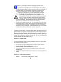
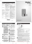
1
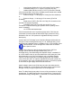
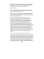
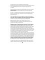
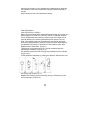
Installation, Operation, and Service Manual
TM
Nitro-Draught - 1000
TM
Nitro-Draught - Pro
TM
Nitro-Draught - Max
Blend Gas Dispense Systems
Section 1 – Introduction
The Nitro-Draught brand blend gas dispense system extracts nitrogen
(N2) from ambient air, blends it with carbon dioxide (CO2) and supplies
the mixed gas to a draught beer dispense system. As a component of a
properly designed and maintained beer system, the Nitro-Draught
assures brewery quality beverage presentation while it eliminates
excessive foaming and wasted beer.
The Nitro-Draught system uses proven Pressure Swing Adsorption
(PSA) technology with Carbon Molecular Sieve (CMS) to separate N2
from the atmosphere and store it at a purity level of at least 99.8%. It
uses a mechanical blender to combine the N2 with CO2 from another
storage vessel into two CO2 / N2 “beer gas” blend ratios, commonly 25%
/ 75% and 60% / 40% respectively. These blends are consistent and
accurate to within 2% CO2 of each blend ratio. Blends can be
customized for any application.
This manual contains the information necessary for the correct use of the
Nitro-Draught 1000, Nitro-Draught Pro and Nitro-Draught Max. Should
any questions arise regarding safe and proper installation, operation or
maintenance of the Nitro-Draught system, contact the supplier before
proceeding.
Warning: Ensure that all personnel involved in the installation,
operation and maintenance of the Nitro-Draught system, as
well as those persons who will act as supervisory personnel,
have read and fully understand the instructions before attempting to
install, operate or perform maintenance on the unit.
2
Section 2 – Contents
Section 1 Introduction page 1
Section 2 Contents of the Operating Manual page 2
Section 3 Alert Symbols page 3
Section 4 Safety Warning page 3
Section 5 General Information, System Schematics page 4
Section 6 Possible causes of blend gas pressure loss page 6
Section 7 System Leaks page 6
Section 8 Product Specifications page 7
Section 9 Unpacking the Nitro-Draught unit page 8
Section 10 Installation and Operation of the unit page 8
Section 11 Maintenance page 11 Section 12 Troubleshooting Guide
page 14
Section 13 Service and Parts page 15
Section 14 P & I Diagram / Electrical Wiring Diagram page 16
Section 15 Warranty page 17
3
Section 3 - Alert symbols used throughout this manual
WARNING: The WARNING symbol draws attention to an
operating procedure or practice that can cause injury if it is not
observed or performed correctly. Do not continue past a
WARNING symbol until you have fully understood or satisfied
the indicated conditions.
CAUTION: The CAUTION symbol draws attention to an
operating procedure or practice that can damage the unit if it is
not observed or performed correctly. Do not continue past a
CAUTION symbol until you have completely understood or
satisfied the indicated conditions.
NOTE: The NOTE symbol draws attention to information that
is especially important to an operating procedure or a practice
that is advisable to perform correctly or observe correctly, but
that cannot damage the unit.
Section 4 - Safety Warning
Do not operate the Nitro-Draught unit until the information
contained in this document has been read and understood by all
personnel concerned. The unit should be connected to an
electrical supply in accordance with local safety regulations. Ensure that
the rating plate corresponds to the supply voltage. Ensure that the unit
is grounded.
Nitrogen (N2) & carbon dioxide (CO2) are not poisonous gases but in a
concentrated form present a risk of asphyxiation. The Nitro-Draught unit
produces a small flow of mixed gases that quickly disperse in the
atmosphere. However, do not directly inhale any gases produced by the
unit. Refer to Compressed Gas Association publications for further
information.
Before service or maintenance is performed on the Nitro-Draught
system, the electrical supply must be switched off and the main electrical
cord disconnected. All personnel handling, using or maintaining the
Nitro-Draught unit must employ safe working practices and observe all
relevant local health and safety regulations.
4
Section 5 - General Information
CO2 is supplied to the Nitro-Draught from a bulk storage vessel or high
pressure CO2 cylinder. The CO2 to the Nitro-Draught should be regulated
to between 90 – 300 psi. The Nitro-Draught produces nitrogen (N2) by
separating it from the atmosphere using a Carbon Molecular Sieve
(CMS). The N2 is stored in an external receiver vessel.
While
producing N2 the internal sieve column will depressurize on a
regular 1-3 minute cycle, resulting in an audible pulse of gas, which
is normal. By blending the CO2 with the N2, Nitro-Draught units will
output up to two different mixtures of carbon dioxide (CO2) and nitrogen
(N2) simultaneously at pre-determined ratios. Unblended nitrogen can be
dispensed from the external nitrogen storage vessel if needed. The
standard blend ratios can be customized if the application requires.
Standard blends are:
Blend 1 = 25% CO2 / 75% N2
Blend 2 = 60% CO2 / 40% N2
Nitro-Draught units are classified as non-hazardous for transportation
purposes and non-flammable for fire regulations. Any interference with
the calibration warning labels will invalidate the Nitro-Draught unit
warranty and may incur costs for re-calibration.
5
6
7
Section 6 – Possible causes of blend gas pressure loss
•
•
• Check the on/off switch (No.7 on Schematic B) on the side of
the Nitro-Draught cabinet to ensure the green switch is illuminated. If
the green switch is not illuminated, check that the power cord is
securely connected to the unit and to the power supply outlet
and that any external fuse or circuit breaker has not tripped.
Check the keg tap couplings to be sure they are secure.
• Check the CO2 inlet gauge on the unit (location No. 2 on
Schematic B), to verify that the supply pressure is at least 60
psig (4.1 barg). If the gauge pressure is low, switch to the
regulated back-up cylinder (if equipped). Regulate the backup source to 90 psig. With assistance from your service supplier,
determine and correct the cause of low CO2 pressure.
Check the N2 supply pressure (No. 4 on Schematic B) to verify that it
is above 60 psig (4.1 barg). If the pressure is below this figure, bring
the regulated back-up cylinder (if equipped) into service. Regulate
the back-up source to 90 psig. Call for assistance from your supplier
to determine and correct the cause of low N2 pressure.
If either the CO2 supply or the N2 supply stops, the blender within the
Nitro-Draught unit will stop supplying gas to the beer dispense system.
Blend production will resume when gas pressure is restored. If either of
the gas input supply pressures drops but stays above keg pressure, the
blender will continue to produce blended gas, but at a corresponding
slower rate and with less blend accuracy.
Section 7 - System Leaks
If a loss of pressure is due to obvious leakage or rupture of a gas supply
line, take the following actions:
•
•
•
•
Do not enter the area of leakage until it is safe to do so (refer to
supplier Material Safety Data Sheets).
Ensure the area is well ventilated before entering.
Turn off all cylinders if they are accessible and are away from the
leakage area.
Switch off the Nitro-Draught unit and contact your service supplier for
advice.
Section 8 - Product Specifications
•
Model:
Nitro-Draught 1000 (Part No. 79001)
8
•
•
•
•
•
•
•
•
•
•
•
•
•
•
Nitro-Draught Pro (Part No. 79002)
Nitro-Draught Max (Part No. 79003)
Dimensions:
Height - 24.5in /623mm (1000, Pro), 31in /785mm (Max)
Width - 13.6in /345mm
Depth - 14.8in /375mm
Total Weight:
Nitro-Draught 1000, Pro - 77lb/35kg
Nitro-Draught Max - 110lb/50kg
Mounting Hole Spacing:
16 in (Horizontal) center to center
Electrical Power Supply:
115 Vac 60 Hz
Ambient Temperature:
36 to 95ºF (+2 to +35ºC)
N2 Storage Vessel Size:
Approx 30 gal/ 114 liters (Part No.
77001)
N2 Production Rate:
Nitro-Draught 1000 - Approx 0.035 cfm (1 L/min)
Nitro-Draught Pro - Approx 0.07 cfm (2 L/min)
Nitro-Draught Max - Approx 0.175 cfm (5 L/min)
Nitrogen Purity:
>99.8% (<0.2% oxygen)
N2 Generation Cycle Start/Stop Pressures:
ND 1000, Pro - 94psig (6.5barg) / 102psig (7.0barg)
ND Max – 131psig (9.0barg) / 138 psig (9.5barg)
Stored N2 Volume @ Max Press:
3
ND 1000, Pro - 31 ft (approx. 876 L)
3
ND Max - 42 ft (approx. 1190 L)
Min CO2 Gas Requirement: 90 psig (6.2 barg)
Mixed Blends (CO2 /N2):
(25% / 75%) & (60% / 40%)
Blend Outlet Pressure:
72.5 psig (5 barg)
Inlet and Outlet Bulkhead Ports: 1/4” FNPT
Section 9 – Unpacking the Unit
Remove the items from the box and check for damage. The box contains
one Nitro-Draught unit, a manual, wall mounting assembly and a bag
containing a power cord. If any of the items are in a damaged condition,
request an immediate inspection by the carrier. If any of the items are
missing, please contact Fizz.
Section 10 – Installation and Operation
The Nitro-Draught unit can be either mounted to a wall or on top of a
suitable flat surface. A suitable surface is one that will support the
weight and vibration of the unit as well as protect the unit from damage
9
from impact, moisture, excessive heat etc. The Nitro-Draught units must
be mounted in a vertical position.
The location for mounting the Nitro-Draught unit should be indoors in an
area that is well ventilated and where the ambient temperature is
between 36ºF and 95ºF. Ensure that the wall or supporting member of
the wall is capable of bearing 110 lb (50kg). The mounting location must
have access to a 115V ac electrical supply with a three pin socket.
Ensure that the electrical supply circuit has adequate capacity for
consistent power supply to the compressor motor. Take into account the
location of a properly regulated CO2 source and space for the N2 storage
tank. The N2 storage tank CAN be located distant from the Nitro-Draught
unit with no adverse effects on the operation of the system. Make sure
the mounting position allows access to the side of the cabinet for making
connections and for viewing operational displays.
The attachment means, must be suitable for the type of wall construction
and capable of supporting the full weight the Nitro-Draught unit, which is
approximately 77lb (35kg) for Nitro-Draught 1000 / Pro and 110lb (50kg)
for Nitro-Draught Max. PLEASE WEAR EYE PROTECTION WHILE
INSTALLING THE UNIT.
The use of noxious chemicals or machinery that produces fumes is not
permitted within a 20 ft. radius of a Nitro-Draught installation site.
Ensure that there are no electrical devices below the Nitro-Draught unit,
as condensate (water) may drip from the Nitro-Draught unit.
Wall Mounting Kit Description and Instructions
The Nitro-Draught system is supplied with a kit to be used for wall
mounted installations. It is the installer’s responsibility to use proper
fasteners and installation techniques to ensure a safe installation. Pay
particular attention to the weight of the unit and the tendency for vibration
to loosen fasteners. Use Loctite or similar products to lock all fasteners.
This illustration is meant to demonstrate the function of each part
contained in the installation kit. Proper mounting of the brackets to the
wall is the installer’s responsibility and will vary depending on the wall
construction.
Items Contained in Kit
10
Step One
Using a level; mark wall using OUTER holes in Cross Bar. These marks
will locate the mounting holes for the Wall Brackets. Fasten Wall
Brackets to wall using appropriate fasteners for type of wall construction.
Step Two
Bolt Cross Bar to outside back of Nitro-Draught through INNER holes on
Cross Bar using supplied slotted bolt and nuts. Bolt Rubber Bumper to
lower back of Nitro-Draught if needed.
11
Step Three
Hang Nitro-Draught by resting Cross Bar into Wall Brackets. Lock Cross
Bar to Wall Brackets by screwing the provided phillips head screws
through OUTER holes in wall brackets.
Supplies To Have On Hand (not supplied with Nitro-Draught unit):
•
Reinforced Beverage Tubing (red line) 1/4” ID (Fizz P/N 14010)
12
•
Hose Clamps (Oetiker #13.3) for 1/4” tubing (Fizz P/N 13001)
•
Hose Barb Fittings (1/4” x 1/4 NPT) (Fizz P/N 1611322)
•
Isolation (Ball) Valves (1/4 NPT x 1/4 FPT) (Fizz P/N 1716162)
(One recommended in each line to facilitate pressure tests and to isolate
components for service and switch over)
•
Pressure Gauge, * 0-160 psig (1/4” CUM) (Fizz P/N 10919416)
or
•
Pressure Gauge, * 0-160 psig (1/4” bot mount) (Fizz P/N
2014649)
•
Street tee (1/4” NPT) (Fizz P/N 1211702) (For connection of an
optional CO2 supply line gauge)
•
Hose Barb Tees (1/4”) (Fizz P/N 1611612) (For in-line
connection of optional back-up gas cylinders and for “splitting” blend
lines if necessary)
•
1/2” PTFE thread sealant tape
Fizz recommends the use of a pressure gauge at the CO2 inlet port
(Schematic A) to assure that at least 90 psi supply pressure is being
delivered to the unit. CO2 pressure is regulated internally to ensure
blend purity.
Connect the “N2 To Storage” port of the Nitro-Draught cabinet with the
inlet port on the N2 storage tank using 1/4” I.D. beverage tubing, hose
barb fittings and stepless clamps. Installation of an ‘in-line’ isolation valve
is recommended. The N2 storage tank is fitted with an isolation
valve. Open this valve.
Connect the outlet port of the N2 storage tank with the “N2 From
Storage” port on the Nitro-Draught cabinet using 1/4” I.D.
beverage tubing, hose barb fittings and stepless clamps. Installation of
an in-line isolation valve is recommended either at the outlet port of the
N2 storage tank or the “N2 From Storage” port on the Nitro-Draught
cabinet. (The N2 storage tank is already equipped with this isolation
valve.) Close this valve. An optional, regulated back-up N2 cylinder can
be connected in-line using a barbed tee connection. If a back-up cylinder
is connected, its gas supply valve should be turned off.
Attach isolation valves to the CO2 inlet port and to the outlet ports for
Blend 1 and Blend 2 on the cabinet. Close these valves. Now the NitroDraught is ready to begin N2 generation for the storage tank.
Note: The Nitro-Draught may take 14 hours to fully pressurize an “empty”
storage tank. The Nitro-Draught Pro unit will require 6 to 7 hours to fully
pressurize an empty storage tank. To save time, Fizz recommends that
13
the storage tank be pre-pressurised to 80 - 90 psig using a regulated
supply of N2 from a high- pressure cylinder. Complete the storage tank
pressurization by operating the unit to assure that the system is
performing properly and is ready to be put into service.
Electrical Power-Up
The unit must be connected to a suitable 115V ac grounded electric
supply in accordance with local safety regulations. Ensure the rating
plate corresponds to the supply voltage.
Ensure there is power at the 3-pin (grounded) socket. Using the power
cord supplied with the Nitro-Draught unit, connect the unit to the power
supply. Switch the ON/Off Main Switch to the “ON” position and ensure
that the green switch illuminates.
Note: The cooling fan motor will start immediately and after
approximately 120 seconds the on-board compressor will start. The
Nitro-Draught’s nitrogen generation process will consist of an
approximate 1 1/2 minute compressor run time alternating with an
exhaust time of about two minutes. The Nitro Draught Pro’s nitrogen
generation process will consist of an approximate two minute
compressor run time alternating with an exhaust time of about 1 1/2
minutes. The Nitro Draught Max’s nitrogen generation process will
consist of an approximate two minute 10 seconds compressor run time
alternating with an exhaust time of about 2 minutes. An audible pressure
release will indicate that the unit is producing N2. In normal operation
this audible cycle will continue. In the event of low or zero flow
requirement the cycle will continue until the N2 storage vessel is fully
pressurised where upon the unit will cease cycling and shutdown. This
energy saving mode is shown via the green Economy Light on the side
of the unit. When the pressure falls the unit will re-enter normal
operation.
Locate and Connect the CO2, Blended Gas and Pure N2 Lines
While the N2 storage tank is being pressurised, determine a connection
point to the main CO2 supply line. (Ensure that the CO2 supply pressure
is at least 90 psi.) Determine the blend gas supply line connection points
to the draught beer system and to the pure N2 use connection point as
needed. Final connections and leak testing will cause a brief interruption
of service to the beer faucets and should be accomplished when the
establishment is closed or when no beer is being poured. Make the CO2
and the blend gas supply line connections after the N2 storage tank is
14
fully pressurised to minimize draught system downtime.
Be sure the gas supply (pressure) from the CO2 storage vessel is turned
off or restricted at the connection point before making the CO2
connection.
Connect the CO2 inlet port on the Nitro-Draught unit to the CO2 supply
line connection point using beverage tubing, hose barb fittings and
stepless clamps.
Run the 1/4” ID blend-gas supply lines from the Nitro-Draught unit to the
beer gas connection points. Connect the lines to the Nitro Draught’s
blend supply points.
Color-coded supply lines are recommended to make sure that Blend 1
(25% CO2 / 75% N2) and Blend 2 (60% CO2 / 40% N2) are routed to the
correct beer types. For example, red-line beverage tubing may be used
for Blend 1 and green-line beverage tubing used for Blend 2.
Relieve pressure at the beer gas connection points. Avoid
depressurizing the kegs. Connect the blend-gas supply lines to the
designated beer gas connection points.
Restore the main CO2 supply pressure. Open the “CO2 inlet” valve on
the Nitro-Draught unit. Open the “N2 From Storage” valve. All isolation
valves except the blend outlet isolation valves should now be open.
Observe pressure gauges and examine all connections for leaks. When
the N2 storage tank is fully pressurised and the N2 pressure gauge
remains steady, the Nitro-Draught unit should be in the “rest” mode and
the compressor will be off. If the N2 pressure falls while the blend outlets
are closed this indicates leakage in the upstream connections or within
the Nitro-Draught unit. Locate and correct the leak(s).
To check for blend-gas leaks to the beer system, open the red valves on
the blend-gas pressure control modules. Pressurize the blend gas supply
lines by adjusting the regulators to the proper beer system specifications.
Ensure that no beer is being dispensed. The N2 supply pressure gauge
may show a small pressure drop at first but should stabilise. Blend-gas
line pressure should be stable at the pressure set by the beer system
installer. If pressure continues to drop, locate and correct the leak(s) in
the draught system. (Ensure that all beer tap couplings are secure.)
The beer-gas system may have leaked before the Nitro-Draught was
installed. Leaking keg tap couplings are common. The leak(s) likely go
15
unnoticed (except through excessive gas consumption). If that is the
case, the Nitro-Draught’s compressor may run excessively or appear to
be unable to keep the N2 storage tank adequately pressurized during offbusiness hours. Check all gas line connections, including the keg
couplings, for leaks.
Section 11 - Maintenance
Before performing maintenance on a Nitro-Draught unit, disconnect the
main power supply.
Failure to perform specified service may result in damage to the NitroDraught unit and may invalidate any warranty. Use only genuine parts as
supplied by Fizz.
The quality and reliability of the Nitro-Draught unit is maintained through
preventive maintenance performed on a scheduled, regular basis.
16
Although the frequency of this maintenance is determined by particular
use conditions, Fizz recommends filter changes at least every twelve
months.
Keep a written record of all maintenance activity.
Filter Replacement
(Use Filter Kit P/N 11705321)
Switch off the electrical power supply before performing any service on a
Nitro-Draught unit. Close the “CO2 Inlet” and N2 To Storage” Isolation
valves. Depressurise the system by switching the unit on again for 20
seconds allowing it to exhaust (and depressurize). Shut the unit off.
Note: If the storage system is full pressurized, the internal tubing will
need to be depressurized by slowly turning out the drain tube retaining
nut attached to the elbow on the bottom of the coalescing filter bowl.
Replace the Air Intake Filter: (Figure 1)
Twist the cap of the filter housing in a counter clockwise direction
separating it completely. (Figure 1a) 2.)
Pull the filter element from the housing cap and dispose of the element.
(Figure 1b) 3.)
Fit the replacement element by pushing the element, wide end first, into
the housing cap. (Figure 1c) 4.)
Replace the housing cap (with new filter) turning it clockwise by hand
until it snaps tight. (Figure 1d)
17
Figure 1
Replace the Coalescing Filter: (Figure 2)
1.) Make sure the housing is completely depressurized before
continuing.
2.) Unscrew the bowl and remove the head. (Figure 2a & 2b)
3.) Remove the element from the bowl and dispose in accordance with
local waste regulations. (Figure 2c) 4.) Carefully remove the element
from the packaging and insert into the bowl.. (Figure 2d) 5.) Replace the
head and screw onto the bowl. (Figure 2e)
Figure 2
Ensure the internal pressure is completely relieved by slowly unscrewing
the tube retaining nut on the elbow at the bottom of
the filter housing bowl. Disconnect the drain tube. Do not remove the
elbow from the housing.
2.)
Unscrew the bowl and remove the head. (Figure 2a & 2b)
3.)
Remove the element from the bowl and dispose in accordance
with local waste regulations. (Figure 2c)
4.)
Carefully remove the element from the packaging and insert into
the bowl.. (Figure 2d)
5.)
Replace the head and screw onto the bowl. (Figure 2e)
6.)
Refit the drain tube to the filter housing bowl.
Replace the Silencer Filter Assembly: (Figure 3)
1.)
Unscrew the silencer (counter clockwise) from the solenoid valve
(Figure 3a). Dispose of the silencer. Notice that the silencer is comprised
of an outer, blue porous plastic “housing” with a sintered brass insert.
Both pieces are replaced and therefore do not need to be separated
unless for disposal reasons.
18
2.)
Screw the replacement silencer onto the solenoid valve’s fitting
until it is hand tight. (Figure 3b)
19
Section 12 - Troubleshooting Guide for Service Agent
Indication
Possible Cause
Corrective Action
Poor power cord connection / blown
power fuse
Be sure the power cord is securely connected
to the power supply outlet and to the unit.
Check / replace 10A fuse located in power
socket
Incorrect input voltage
Check ‘main’ voltage and rating number plate
for voltage spec
External fuse blown or circuit
breaker tripped
Check fuse; replace if necessary. Reset circuit
breaker; check for overload
On/Off switch failure
Verify power to unit. Replace switch.
Unit is in economy mode until
storage pressure to 94 psi
Check green economy light
Internal leak in Nitro Draught unit
Close “N2 outlet to storage” valve, run unit to
max pressure, check and correct compressed
air and N2 pressure circuit / fitting leaks
Leak in N2 storage or supply line
Leak-check line fittings and connections.
Correct leak(s)
Leak in beer gas circuit or keg
coupling
Ensure keg tap couplings are secure. Check
gas line and regulator connections
Power off
Check on/off switch and power circuit
Low CO2 inlet (line) gauge pressure
(below 60 psi)
Check CO2 supply (tank) pressure and
contents. Ensure valves are open
Out of CO2
Switch to back-up CO2 if equipped. Have CO2
storage tank refilled
Low N2 storage pressure (below 60
psi)
If green and amber LED’s are on and
compressor is cycling
Temperature problem
Check cooler and pour temperatures
Incorrect dispense gas pressure
Check pour rate. Check dispense gas pressure
at the keg. Consult with beer system installer
or beer distributor
Green power switch not Illuminated
Green power switch illuminated but no operation
N2 storage (tank) pressure drops during period
of no use. Compressor motor runs excessively;
unable to reach maximum N2 storage pressure
Low blend gas pressure; beer pouring slow
Excessive beer foaming
20
Section 13 - Service and Parts
Service and Maintenance
1.)
Service or maintenance on the Nitro Draught - 1000, Nitro
Draught Pro and Nitro Draught Max should be performed only by Fizz
trained and authorised professional service agents who are familiar with
mixed gas pressure systems and all pertinent safety and service
procedures. Fizz recommends the use of Fizz approved replacement
parts.
2.)
Before calling your service agent or CO2 supplier for service or
troubleshooting assistance, please have the following information:
-Serial number of the Carbo-Draught unit
-Description of the situation
Readings from pressure gauges (CO2 supply, N2 storage, Gas Blend
Supply) Temperature of cooler and beer at faucet if appropriate.
-Special observations such as excessive beer foaming or continuous
compressor operation.
3.)
Fizz recommends that a thorough preventive maintenance check
be performed on the Nitro Draught - 1000 and on the Nitro Draught Pro &
Max system annually by a qualified professional service agent.
Replacement of the compressor air inlet filter, the coalescing filter, and
the silencer filter assembly should be performed at least every twelve
months or more frequently, depending on environmental conditions.
Filter kit: Fizz P/N 11705321.
4.)
The Nitro Draught units have no user serviceable parts. All
service work should be performed by an authorised professional service
agent.
Service or modifications performed on the system by unauthorised
persons will void the warranty.
Important Telephone Numbers:
Nitro Draught System Installer:
___________________________________
Nitro Draught / CO2 Service Agent:
_______________________________ Fizz Dispense Optimization
Group: (800) 253-6610 [toll free in U.S] http//shop.fizzdog.com
21
22
23
Section 15 - Warranty
Warranty Policy
Fizz Dispense Optimization Group, LLC warrants to the Purchaser the
Nitro Draught System shall be free from any defects in workership and
materials for 24 months from the date of shipment from Fizz. Purchaser
agrees that as a pre-condition to any Fizz liability hereunder, Purchaser
or its appointed agents shall fully inspect all goods immediately upon
delivery and shall give Fizz written notice of any claim or purported
defect within ten (10) days after discovery of such defect. Use of the
Carbo-Draught system without the recommended inlet air quality
(Section 10 of this manual) or genuine parts will expressly invalidate the
warranty.
As a further pre-condition to any Fizz liability hereunder, parts
replacement and labour must be supplied by a Fizz approved service
company. Fizz may elect to repair or replace such equipment or any
defective component or part thereof which proves to be defective, or to
refund the purchase price paid by the original Purchaser. Fizz shall not
be liable for defects caused by the effects of normal wear and tear,
erosion, corrosion, fire, explosion, misuse, or unauthorised modification.
Alterations or repair by others than those designated and approved by
Fizz or operation of such equipment in a manner inconsistent with Fizz
accepted practices and all operating instructions, unless pre-authorised
in writing by Fizz, shall void this Warranty.
Fizz’s sole and exclusive liability under this Warranty is to the Purchaser
and shall not exceed the lesser of the cost of repair, cost of replacement,
or refund of the net purchase price paid by the original Purchaser. Any
accessories, parts and equipment supplied by Fizz but not manufactured
by Fizz shall carry whatever warranty the manufacturer has given to Fizz
providing it is possible for Fizz to pass on such warranty to the customer.
Fizz is not liable for any losses (including CO2), damages, or costs of
delays, including incidental or consequential damages. Fizz specifically
makes no warranties or guarantees, expressed or implied, including the
warranties of merchantability or fitness for a particular purpose or use,
other than those warranties expressed herein.
WARRANTY CLAIMS PROCEDURE
1.)
All warranty claims must be previously authorized by Fizz Inc.
Telephonic / electronic approval may be obtained by contacting Fizz Inc.
Technical / Customer Services at:
-Telephone: 0800 - 253 - 6610
24
-Facsimile: 678 - 792 - 7784
or by writing to:
Fizz Dispense Optimization Group, LLC PO Box 1003 ADAIRSVILLE GA
30103 USA
2.)
Authorization must be obtained from Fizz prior to shipping any
equipment to Fizz facilities. The model and serial number of
the unit must be provided in order to process the return. If approved, a
Return Material Authorisation (RMA) number will be
provided. The RMA number must be prominently indicated on the
packing slip and any packaging that accompanies the
goods being returned. The customer returning the goods is responsible
for all freight, proper packing, and any damage
incurred during shipment of the goods back to Fizz.
25
26
27