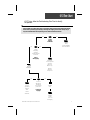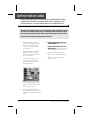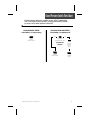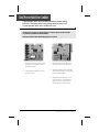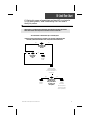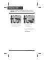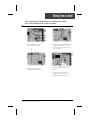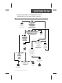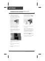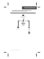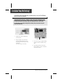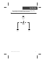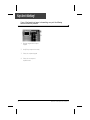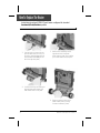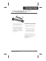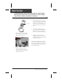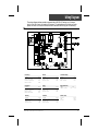
1
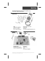
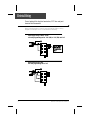
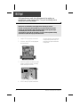
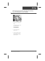
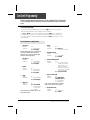
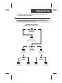
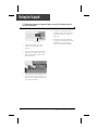
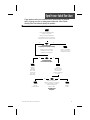
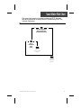
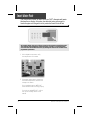
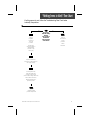
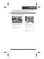
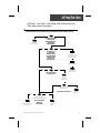
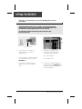
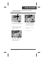
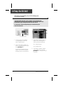
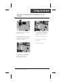
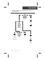
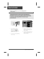
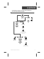
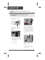
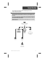
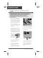
MSPA-MP-CE METAPACK
MSPA-MP-SR4-CE VERSION SERVICE MANUAL
• Gecko Electronics Inc. •
Visual step- by-step guide to easily
identify & correct technical problems!
Table of Contents
Power & Ground Check
Tools and Parts
GFCI & Electrical Wiring
3
4
Programming
Low Level Programming
8
Error Conditions / Display Messages
Wrong Temperature Appearing on Keypad Display
Display is Flashing
3 Flashing Dots Appearing on Keypad Display
Open Pressure Switch
Closed Pressure Switch
Hi-Limit
Smart Winter Mode
9
11
15
17
19
21
23
Troubleshooting
Nothing Seems to Work!
Spa Does Not Heat!
Jet Pump 1/Jet Pump 2 Does Not Work!
Blower Does Not Work!
Light Does Not Work!
Ozonator Does Not Work!
Circulation Pump Does Not Work!
Keys Do Not Work!
25
29
33
39
43
45
47
49
How to ...
Replace The Board
Replace The Heater
Test a Fuse
51
55
58
Miscellaneous
Wiring Diagram
Professional Repair Kit Info
59
60
Note: For spa repairs and troubleshooting with Pocket-tek technology, please refer to Pocket-tek
User's Manual available from Gecko and at www.pocket-tek.com.
In an attempt to make this manual as useful as possible, it has been presented in two
formats. Problem-solving solutions are described with Troubleshooting Flow Charts
and also with Step-by-Step Procedures.
The two formats together should provide an overall complete explanation, with flow
charts providing an overview of specific problems, and step-by-step procedures giving
more detailed information.
TO SUCCESSFULLY TROUBLESHOOT SPA PACK PROBLEMS, IT IS ESSENTIAL TO HAVE
AN UNDERSTANDING OF THE OPERATION AND FEATURES OF THE SPA PACK BEING
WORKED ON. CONSULT THE OWNER'S MANUAL, SUNRISE SPAS OR GECKO
ELECTRONICS FOR DETAILS.
Important Safety Information
WARNING: Risk of electrical shock! All procedures described in this service manual
must only be performed by qualified personnel, in accordance with the
standards applicable in the country of installation and, whenever
possible, with the equipment powered off. When connecting the
equipment, always refer to the wiring diagram affixed to the inside of
your spa pack’s power box cover! This diagram always prevails over
the wiring diagram at the end of this manual.
All information given subject to technical modifications without notice.
Tools & Parts
The tools, test equipment and components needed to carry
out MSPA-MP Spa Pack service calls.
Required tools:
Pliers
Phillips & flat screwdrivers
M8 (11/32") nut driver
M6 (1/4") open end wrench
M10 (3/8") open end wrench
Jumper cable
Multimeter
GFCI tester & digital thermometer (optional)
Required
pack parts:
Regulation sensor
MSPA-MP-SR4-CE system
board (or complete spa pack)
Transformer
Pressure switch
Fuses
Top side control (keypad)
Gecko Electronics Inc. sells Professionnal Repair Kits that include everything needed for MSPA-MP Spa Pack servicing.
For more information, go to the last page of this manual.
Electrical Wiring
Correct wiring of the electrical service box, GFCI box and pack
terminal block is essential.
•
Make a visual inspection to check for signs of miswiring. Refer to wiring
diagram on inside pack cover. Call an electrician if necessary.
Input supply wiring 1 x 16A or 1 x 32A
Low level programming set for "Cu2" (16A) or "Cu1" (32A) and "In1"
Input supply wiring 3 x 16A
Low level programming set for "In3"
4
MSPA-MP-CE Metapack Service Manual
GFCI Flow Chart
If GFCI trips, follow this Troubleshooting Flow Chart to identify
the problem:
A Ground Fault Circuit Interrupter (GFCI) is an electrical safety protection device that guards against
electrocution by monitoring and reacting to incoming and outgoing current levels. The spa may or
may not be installed with a GFCI depending on local electrical standards and laws.
yes
no
Is GFCI
properly
connected?
yes
Verify
Wiring Diagram
and reconnect it.
no
Unplug
everything,
including
heater and light
cord wires.
Is GFCI
still tripping?
Reconnect
one component
at a time
until GFCI
starts to trip.
Replace
transformer.
Replace
defective
component.
yes
There is
a problem
with the
cable.
Call an
electrician.
no
If GFCI is
still tripping,
disconnect
the incoming
power line.
Replace
GFCI.
Is GFCI still
tripping?
Replace
board
if GFCI is
still tripping.
MSPA-MP-CE Metapack Service Manual
5
GFCI Trips!
If all connections are made, but nothing seems to be working, you
probably have a power supply problem. Carry out the following tests to
identify and correct the problem:
Note that for new installations, GFCI trippings due to miswiring are common.
If breaker is wired properly, GFCI trippings may occur when total amount of current
drawn by spa exceeds breaker rating. This is highly unlikely as each spa pack output
is individually fused, and fuses will blow before GFCI trips.
A current leak to ground will also cause GFCI to trip. If any of the components is faulty
and a leak occurs, GFCI will trip to prevent electrocution.
1• Verify if GFCI is properly connected.
2• If it is not, verify GFCI wiring diagram
and reconnect it.
If it stops tripping, reconnect one
component at a time until GFCI
starts tripping. Replace defective
component.
3• If GFCI is properly connected, but still
tripping, unplug all outputs, including
heater and light cord wires.
4• If GFCI still trips, replace transformer.
6
MSPA-MP-CE Metapack Service Manual
GFCI Trips!
If GFCI continues to trip even after having replaced the transformer,
carry out the following tests to correct the problem:
1• Disconnect incoming power
lines.
If GFCI still trips, there must
be a cable problem.
Call an electrician!
2• If GFCI stops tripping.
Replace GFCI.
3• If GFCI trips again, replace
board. (Refer to "How to
Replace the Board" section
of this manual.)
MSPA-MP-CE Metapack Service Manual
7
Low Level Programming
Certain system operating parameters can be configured from the keypad.
This is normally done by Gecko or the spa installer, but may be done any
time.
Low Level Programming:
To access low level programming, press and hold Light key for 20 seconds, after
which the first parameter code should appear on the display.
Use Up and Down keys to modify parameter values and Light key to change from
one parameter to the next. You must go through all parameters to exit this mode.
If you do not wish to change a parameter, simply press Light key to advance to the
next parameter.
List of parameter configurations
1- Jet Pump 1
Display:
Value of x:
P1 x
1 = single-speed
2 = two-speed
Note: If selecting Jet Pump 1 single-speed,
circulation pump will automatically be
selected and "CP x" will not be displayed
during low level programming.
2- Jet Pump 2
Display:
Value of x:
3- Blower
Display:
Value of x:
4- Light
Display:
Value of x:
5- Fiber box
Display:
Value of x:
P2 x
0 = not installed
1 = single-speed
2 = two-speed
BL x
0 = not installed
1 = single-speed
2 = two-speed
LI x
1 = single-intensity
2 = two-intensity
Fb x
0 = not installed
1 = combined with
12 VAC light
2 = On/Off
Note: If fiber box is installed, light can be
turned on or off only.
8
6- Ozone
Display:
Value of x:
O3 x
1 = always on
2 = on every 30 minutes
7- Circulation pump
Display:
CP x
Value of x:
0 = not installed
1 = installed
8- Current limiting option
Display:
Cu x
Value of x:
1 = HC (High Current),
heater will not start
if more than 3 outputs are on at the
same time (Jet Pump 1,
Jet Pump 2, circulation
pump or blower)
2 = LC (Low Current)
9- Input current mode
Display:
In x
Value of x:
1 = single-phase
(depends on Cu x)
3 = triple-phase
(no restrictions)
Note: Current configuration is ignored if
Input Current mode is 3-phase (In 3).
10- Temperature unit
Display:
Tu x
Value of x:
1 = Fahrenheit
2 = Celsius
MSPA-MP-CE Metapack Service Manual
Wrong Temperature Flow Chart
On certain packs, if system detects that temperature is not within normal
limits, a highly incorrect temperature will be displayed. Follow Troubleshooting Flow Chart below to identify the problem:
Check if regulation
probe is properly connected.
Unplug probe connector
and clean pins on the
board (even a small coating
of film may cause a bad
connection).
Reconnect the probe.
Replace probe with
a spare and verify if
problem is solved.
If it is, replace
probe with spare.
Replace board
if problem persists.
MSPA-MP-CE Metapack Service Manual
9
Wrong Temperature Displayed
Wrong temperature on keypad display indicates a problem with
regulation sensor. The system is constantly verifying if temperature probe
reading is within normal limits.
Note that water temperature must be over 2°C in order to carry out the following steps.
Power may remain On.
3• Reconnect probe.
If wrong temperature is still
displayed on keypad, replace
probe with a spare and place
probe head directly in spa
water.
1• Verify if regulation probe (sensor
located in spa) is properly connected.
If problem is solved, replace
probe.
4• Replace board if problem
persists.
2• Disconnect probe connector
and clean probe connector pins.
Even a small coating of film may
cause a bad connection.
10
MSPA-MP-CE Metapack Service Manual
Display Flashing Flow Chart
On certain packs, if system detects temperature at 44°C or higher, the
display will start flashing. Follow Troubleshooting Flow Chart below to
identify the problem:
yes
no
Press
any key.
A power failure
has occurred.
Has display
stopped flashing?
System
works fine.
yes
no
Are you getting correct
water temp. reading on the display?
yes
no
Is weather
very hot?
Remove
spa cover
(even during
the night).
Start
blower,
if spa is
equipped
with one.
Verify if
temperature probe
is touching water
or if cold air from
back can affect
reading.
If so, replace probe.
yes
Replace
board.
Wait until
spa cools
down (add
cold water
if needed).
Verify if
temperature probe
is properly connected.
no
Display should not
be showing a request
for more heat as water
temperature is above
set point.
Do you get a
230 VAC reading
between
two heater wires
on the board?
Spa construction
and/or installation
may be causing
a rise of water
temperature.
Replace
board
if problem
still persists.
Check cabinet
ventilation.
Pump low speed
is overheating water
during filter cycle.
Lower filter cycle
duration.
MSPA-MP-CE Metapack Service Manual
11
Display Is Flashing
If digital thermometer water temperature reading is 44°C or higher and
keypad display indicates correct temperature, carry out the following
tests:
If display stops flashing after pressing a key, this means that a power failure has occurred.
System works fine.
If weather is very hot:
1• Remove spa cover (even during
the night). Start blower if spa is
equipped with one. Wait until
spa cools down (add cold water
if necessary).
If hot weather is not a factor:
4• If you do not read 230 VAC, check
cabinet ventilation first. If problem
persists, pump low speed may be
overheating water during filter cycle.
Enter Programming mode and
shorten filter cycle duration.
5• If you do read 230 VAC, replace
board.
(Refer to "How to Replace the
Board" section of this manual.)
2• Display should not be showing a
request for more heat as water
temperature is above set point.
3• Remove spa cover. With a voltmeter, read the voltage between
the two heater wires on the board.
12
MSPA-MP-CE Metapack Service Manual
Display Is Flashing
If digital thermometer water temperature reading is 44°C or higher
and keypad display is not showing correct temperature, carry out the
following tests:
1• Verify if temperature probe
is in contact with water and if
cold air from the back could
be affecting readings.
Use foam to isolate probe from
cold air if that is the problem.
2• Make sure temperature probe
is properly connected.
If it is, replace probe.
3• Replace board if display is still
flashing.
(Refer to "How to Replace the
Board" section of this manual.)
MSPA-MP-CE Metapack Service Manual
13
14
MSPA-MP-CE Metapack Service Manual
Flashing Dots Flow Chart
If 3 flashing dots appear on keypad display, follow Troubleshooting Flow
Chart below to identify the problem:
It is recommended that the service person verify low level programming and plug wiring
against the wiring diagram before starting troubleshoot.
3 flashing dots appear on the display!
(Related to Hi-Limit or pressure switch errors)
yes
no
Open pack cover.
Is board LED on?
Flashing dots indicate
hi-limit condition.
Refer to Hi-Limit pages of this
manual to correct the problem.
yes
no
Does spa have
a dedicated
circulation pump?
Disconnect
pressure switch
cable and reconnect it.
yes
no
Turn Jet Pump 1 off
(lower set point or
cancel filter cycle).
yes
Are dots
still flashing?
Open pressure
switch condition.
no
Are dots
still flashing?
Closed pressure
switch condition.
MSPA-MP-CE Metapack Service Manual
Closed pressure
switch condition.
Open pressure
switch condition.
15
Flashing Dots Displayed!
If 3 flashing dots appear on keypad display, carry out the following tests to
correct the problem:
4• If system is not equipped with a
circulation pump, turn Jet Pump 1
off. Lower set point or cancel
filter cycle.
Flashing dots
1• Verify if board LED is on. If so,
refer to Hi-Limit pages of this
manual.
5• If flashing dots are still displayed,
you have a closed pressure switch
condition. If not, you have an
open pressure switch condition.
2• If not, check if the system is equipped with a circulation pump. If it is,
disconnect pressure switch cable
and reconnect it.
3• If flashing dots are still displayed, you
have an open pressure switch condition. If not, you have a closed pressure switch condition.
16
MSPA-MP-CE Metapack Service Manual
Open Pressure Switch Flow Chart
If open pressure switch error condition occurs (problem with the pressure
switch: jet pump is on but no water pressure detected), follow Troubleshooting Flow Chart below to identify the problem:
There must be adequate water
in spa for normal use.
Ensure low level programming
for circulation pump (or Jet Pump 1)
is set properly (see Low Level Section).
yes
no
Is circulation pump
(or Jet Pump 1 low speed) working?
Refer to "Circulation
Pump (or Jet Pump 1)
not Working" section.
(Restart low speed pump by
increasing set point, so that
(3) flashing dots reappear.)
yes
no
Is anything limiting
flow of water into pipes?
Verify if
pressure switch
cable is properly
connected to
pressure switch and
PC board.
Remove
anything
obstructing
filter. Clear
any air locks
and verify
water valves.
yes
Replace
pressure switch.
no
Make sure circulation
pump (or Jet Pump 1 low speed)
is on and short two pressure
switch terminals with
a jumper cable.
Replace
board.
Do flashing dots
disappear?
MSPA-MP-CE Metapack Service Manual
17
Open Pressure Switch Error Condition
Open pressure switch error condition indicates a pressure switch problem.
If system does not detect any pressure when pump is manually or automatically turned on, an open pressure switch error condition will occur.
There must be enough water in the spa for normal operations. System may detect an open pressure switch error condition if spa filter is dirty or if something restricts flow of water in piping.
The heater will automatically shut down when an open pressure switch error condition occurs.
Power may remain On when the following steps are carried out.
1• Verify if circulation pump (or
Jet Pump 1) is working. If pump
is not working, refer to circ.
pump (or Jet Pump 1) section
of this manual.
2• Make sure low level programming for circulation pump (or
Jet Pump 1) is set correctly (see
Low Level Section).
3• Clean filter and check for air
blockages, closed gate valves
or anything that could be restricting water flow.
6• If open pressure switch error condition disappears, replace switch.
7• If open pressure switch error condition persists, the problem may be
either with switch cable or board.
8• Replace board if open pressure
switch error condition still persists.
(Refer to "How to Replace the
Board" section.)
4• Verify if pressure switch cable is
properly connected to pressure
switch and PC board.
5• Ensure adequate water flow in
the heater and short two pressure switch terminals with jumper
cable.
18
MSPA-MP-CE Metapack Service Manual
Closed Pressure Switch Flow Chart
If closed pressure switch error condition occurs, follow Troubleshooting
Flow Chart below to identify problem (usually pressure switch problem jet pump is off but water pressure is detected):
CIRCULATION PUMP SYSTEM:
3 dots flashing - circ. pump running
NON-CIRCULATION PUMP SYSTEM:
3 dots flashing - low speed pump off
yes
Replace
pressure switch.
no
Disconnect
pressure switch cable.
Do flashing dots
disappear?
Replace
pressure switch.
MSPA-MP-CE Metapack Service Manual
Replace
pressure
switch
cable.
Replace
board.
19
Closed Pressure Switch Error Condition
Closed pressure switch error condition indicates a pressure switch
problem. If the system detects any pressure when jet pump is off,
a closed pressure switch error condition will occur.
Flashing dots must appear on keypad display and circulation pump must be turned ON
(or Jet Pump 1 low speed must be turned OFF)!
Power may remain On while the following steps are carried out.
1• Disconnect pressure switch cable
(if system is not equipped with a
circulation pump).
3• If flashing dots are still displayed,
reconnect pressure switch cable.
2• If flashing dots disappear, replace
pressure switch.
4• Replace pressure switch if flashing
dots still appear after reconnecting
pressure switch cable.
5• Replace board if flashing dots do
not reappear on keypad display.
(Refer to "How to Replace the
Board" section of this manual.)
20
MSPA-MP-CE Metapack Service Manual
Hi-Limit Flow Chart
If 3 flashing dots appear on keypad display and board LED is on (potential
Hi-Limit sensor problem), follow Troubleshooting Flow Chart below to
identify the problem:
The Hi-Limit error is related to the Hi-Limit sensor. This means that the system has shut the
heater down because water temperature at the heater barrel has reached 48˚C.
Turn GFCI off then on between each step to reset the system.
Replace board only if the hi-limit error condition is not removed by resetting GFCI after
the initial (3) dots and board LED are seen, and (3) dots and board LED return.
yes
no
Are flashing dots
and board LED
still on?
yes
no
Does heater
barrel feel
hot?
Replace
board.
Verify if anything
is obstructing water
flow (closed valves or
dirty filters).
yes
Replace
board.
no
Do flashing dots
and LED stay on
after power down
or power up of
the system?
System
works fine.
Monitor system
for future hi-limit
sensor problems.
MSPA-MP-CE Metapack Service Manual
21
Hi-Limit Error Condition
The Hi-Limit error condition is related to the Hi-Limit sensor. Carry out
the following tests to identify and correct the problem:
The Hi-Limit error is related to the Hi-Limit sensor. This means that the system has shut the
heater down because water temperature at the heater barrel has reached 48˚C.
Turn GFCI off then on between each step to reset the system.
Replace board only if the hi-limit error condition is not removed by resetting GFCI after
the initial (3) dots and board LED are seen, and (3) dots and board LED return.
Flashing dots
1• Check if flashing dots and board
LED are displayed.
2• If so, check if heater barrel feels
hot.
If it's hot, verify if anything is
obstructing the flow of water
(closed valves or dirty filter).
3• If it's not, replace board.
4• If flashing dots and board LED
are not displayed, verify if anything is obstructing the flow of
water (closed valves or dirty
filter).
5• Power your spa up or down.
If flashing dots and LED are still
displayed, replace board.
22
MSPA-MP-CE Metapack Service Manual
Smart Winter Mode Chart
If jet pumps have started up on several occasions and "AFP" alternates
with water temperature on display, follow this Troubleshooting Flow Chart
to identify the problem:
yes
no
Is the water temperature
of the spa lower than
the desired temperature?
yes
no
Do you
read 230 VAC
to the
heater?
Refer to
"Spa not heating"
section.
The system
is working
properly.
MSPA-MP-CE Metapack Service Manual
23
Smart Winter Mode
If jet pumps have started up several times and "AFP" alternates with water
temperature on display, the system has detected water cold enough to
freeze the pipes and has gone into the protective Smart Winter Mode.
An irregularly flashing "Filter Cycle" indicator means that the system has stopped filtering after
3 hours because water temperature exceeds Set Point by more than 1˚C. If the temperature
cools down before the scheduled end of the cycle, filtering will resume for the remainder of the
programmed cycle duration.
1• With a digital thermometer, verify
the temperature of the water.
2• If the water temperature is lower than
the desired temperature, measure the
voltage to the heater.
If your reading is approx. ≈230 VAC,
Smart Winter Mode is working properly.
If you do not read ≈230 VAC, refer to
the "Spa not heating" section of this
manual.
24
MSPA-MP-CE Metapack Service Manual
"Nothing Seems to Work" Flow Chart
If nothing seems to work, follow the Troubleshooting Flow Chart below
to identify the problem:
yes
Verify if
keypad is
connected
correctly
to board.
All eight pins
must be plugged in
and black wire
must be on top
of the plug.
no
Do you get a
≈230 VAC reading
between
line 1 & neutral
and between
line 2 & neutral
on the board?
There is
an electrical
wiring
problem.
Call an
electrician.
Replace transformer
fuse if there is still nothing on
the keypad display.
If nothing still works,
clean the transformer
orange connector pins
(even a small coating of film may
cause a bad connection).
Replace transformer if
problem persists.
Replace board if
problem still persists.
MSPA-MP-CE Metapack Service Manual
25
Nothing Seems to Work!
If everything is connected, but nothing seems to work, there is probably a
power supply problem. Carry out the following tests to identify and correct
the problem:
1• On the terminal block, measure
voltage between line 1 and neutral.
You should get ≈230 VAC.
2• Measure voltage between
line 2 and neutral.
You should get ≈230 VAC.
3• If you do not get good readings,
this indicates an electrical wiring
problem.
Call an electrician!
26
MSPA-MP-CE Metapack Service Manual
Nothing Seems to Work!
If you are getting good voltage readings, but nothing seems to work,
carry out the following tests to correct the problem:
1• Verify if keypad is correctly
connected to the board.
Xfo
fuse
2• Replace transformer fuse
if nothing still seems to work.
3• If nothing works, clean transformer
orange connector pins. Even a
small coating of film may cause a
bad connection.
4• Replace transformer if problem
persists.
5• If problem is still not solved,
replace board. (Refer to "How
to Replace the Board" section.)
MSPA-MP-CE Metapack Service Manual
27
28
MSPA-MP-CE Metapack Service Manual
"Spa Not Heating" Flow Chart
If the spa does not seem to be heating the water, follow the
Troubleshooting Flow Chart below to identify the problem:
yes
no
Any error conditions
(flashing dots,
flashing display, etc.)
on keypad display
(or is system in
dual set point mode)?
Refer to
specific section
referred to
error condition.
yes
yes
no
Has "Heater" indicator appeared on
keypad display? (If "Heater" indicator is
flashing, system is in LC mode.
See Low Level Section.)
no
Can you read
230 VAC between
two terminals
of the heater
on the board?
yes
yes
no
Take water temperature
and compare with
temp. value displayed
on keypad.
Test/replace
heater fuse.
Replace
board.
no
Replace
board.
Is difference
greater than ±1°C?
Ensure temp.
set point is
higher than
actual water
temperature.
Is temperature
probe touching water
or hot air rear
affecting reading?
Isolate back of
probe with foam.
Are
heater wires
connected
correctly
to the
element?
no
Replace
temperature probe
with spare.
yes
Try tightening wires
to the board & element.
Heating now?
Test/replace
heater assembly.
MSPA-MP-CE Metapack Service Manual
Problem
resolved.
Replace
board.
29
Spa Not Heating!
If the spa does not appear to be heating the water, carry out
the following tests to correct the problem:
1• Check for an error condition on
keypad display. If there is one,
refer to section indicated by the
error condition (or check if system
is in dual set point mode).
2• If there is no error, use a digital
thermometer to take water
temperature and compare your
reading with the temperature
value on the keypad display.
If values are different (±1°C), verify
if sensor is touching water or if hot
air from rear could be affecting
readings.
5• If values are not different, try to
increase temperature by raising
temperature set point. Press Heat
key to increase set point.
"Set Point"
icon
"Heater"
indicator
6• Verify if "Heater" indicator appears
on the display.
"Heater" indicator lights up when
heater is on. It will flash if more heat
has been requested, but heater has
not yet started or if system is in LC
mode (see Low Level section).
If "Heater" indicator appears on the
display, refer to the next page.
If "Heater" indicator does not appear
on the display, replace board.
Use foam to isolate behind the
probe.
3• Replace temperature probe with
a spare one.
4• If spa is still not heating, replace
the board.
30
MSPA-MP-CE Metapack Service Manual
Spa Not Heating!
If "Heater" indicator appears on the display, but spa is still not heating,
carry out the following tests to correct the problem:
If "Heater" indicator lights up on the display:
1• Remove plastic cover and measure
voltage between two heater screws
on the board.
2• If voltage reading is correct, verify
if heater wires are properly connected to the element.
Replace board if you are not getting
a reading of ≈230 VAC.
If not, tighten wires to board and
element.
3• If problem persists, test/replace the
heater assembly.
MSPA-MP-CE Metapack Service Manual
31
32
MSPA-MP-CE Metapack Service Manual
Jet Pump Flow Chart
If Jet Pump 1 or Jet Pump 2 is not working, follow Troubleshooting Flow
Chart below to identify the problem:
Jet Pump speeds and use are determined by spa specifications and Low Level Programming.
yes
no
Any error conditions
(flashing dots,
flashing display, etc.)
appearing on
keypad display?
Refer to
specific section.
yes
no
Does Jet Pump 1
or Jet Pump 2
indicator appear
on keypad display
when you press
Jet Pump 1 or
Jet Pump 2 key?
Verify if low level
programming is
set correctly.
Replace keypad.
yes
no
If still not working,
replace board.
Do jet pumps work
in either speed?
Verify
low level
programming.
no
yes
Test/replace Jet Pump 1 or
Jet Pump 2 fuse.
Jet pump(s) working now!
yes
no
Problem
resolved.
Measure voltage
on the board for both speeds.
Replace Jet Pump 1,
or Jet Pump 2.
Do you get 230 VAC
reading for
both speeds?
MSPA-MP-CE Metapack Service Manual
Replace
board.
33
Jet Pump 1 Does Not Work!
If Jet Pump 1 is not working, carry out the following tests to correct
the problem:
To increase the life of the relay, we use a "snubber" circuit on the jet pump relay.
With this type of circuit, if no pump is connected to an output and relays are open,
the voltmeter will continue reading around 60 volts. This is normal.
It is important to measure voltage when jet pump is connected to pack.
Power must remain On.
"Jet Pump 1" indicator
1• Check for an error condition on
keypad display. If yes, refer to
specific section.
3• If "Jet Pump 1" indicator does
not appear, use a spare keypad
to verify if keypad is defective.
If it is, replace keypad.
2• Verify if "Jet Pump 1" indicator appears
on keypad display when you press
Jet Pump 1 key.
If "Jet Pump 1" indicator does not
appear, check low level programming.
34
If not, replace board.
4• If "Jet Pump 1" indicator appears on
keypad display when Jet Pump 1 key
is pressed, verify if Jet Pump 1 works
in any of the speeds.
MSPA-MP-CE Metapack Service Manual
Jet Pump 1 Does Not Work!
If Jet Pump 1 does not work in any speed, carry out the following
tests to correct the problem:
Jet Pump 1 fuse
1• If Jet Pump 1 does not work in either
speed, test/replace Jet Pump 1 fuse.
2• If replacing the fuse does not work,
or if Jet Pump 1 works in one of two
speeds, take voltage reading on the
board for both speeds.
3• Turn Jet Pump 1 to high speed
and measure voltage between
blue and brown wire connectors:
230 VAC pump: P48 & P65
4• If voltage is correct, replace
Jet Pump 1.
5• If not, replace board.
Turn Jet Pump 1 to low speed and
measure voltage between blue
and black wire connectors:
230 VAC pump: P48 & P37
MSPA-MP-CE Metapack Service Manual
35
Jet Pump 2 Does Not Work!
If Jet Pump 2 is not working, carry out the following tests
to correct the problem:
To increase the life of the relay, we use a "snubber" circuit on the pump relay.
With this type of circuit, if no pump is connected to an output and relays are open,
the voltmeter will get a reading of around 60 volts. This is normal.
It is important to measure voltage when pump is connected to the pack.
Power must remain On.
"Jet Pump 2" indicator
1• Check for any error conditions
on keypad display. If there are,
refer to specific section.
2• Verify if "Jet Pump 2" indicator appears on keypad display when you
press Jet Pump 2 key.
If "Jet Pump 2" indicator does not
appear, check low level programming first (see Low Level Section).
36
3• If "Jet Pump 2" indicator does not
appear, use a spare keypad to
verify if spa keypad is defective.
If it is, replace keypad.
If not, replace board.
4• If "Jet Pump 2" indicator appears
on the display when you press
Jet Pump 2 key, verify if Jet Pump 2
is working.
MSPA-MP-CE Metapack Service Manual
Jet Pump 2 Does Not Work!
If Jet Pump 2 is not working, carry out the following tests to correct
the problem:
Jet Pump 2 fuse
1• If Jet Pump 2 does not work, test/replace Jet Pump 2 fuse.
2• If replacing the fuse does not work,
or if Jet Pump 2 works in one of two
speeds, take voltage reading on the
board for both speeds.
3• Turn Jet Pump 2 to high speed
and measure voltage between
blue and brown wire connectors:
230 VAC pump: P45 & P35
4• If voltage is correct, replace
Jet Pump 2.
5• If not, replace board.
3• Turn Jet Pump 2 to low speed and
measure voltage between blue
and black wire connectors:
230 VAC pump: P45 & P22
MSPA-MP-CE Metapack Service Manual
37
38
MSPA-MP-CE Metapack Service Manual
Blower Flow Chart
If blower is not working, follow this Troubleshooting Flow Chart to
identify the problem:
yes
no
Does "Blower"
indicator appear
on keyboard display
when you press
Blower key?
yes
no
Replace
keypad.
Do you
read
≈230 VAC for
230 VAC blower
at blower
output on
the board
(in high speed)?
yes
It's possible
that blower
is not getting
enough air entry.
Verify
low level
programming.
Replace
board.
no
Does
blower restart
after a few minutes
(to cool down
after being
shut off?)
Replace
blower.
Replace
blower
fuse.
Create an opening
to allow more air
under spa skirt.
Replace board
if blower
still does
not start.
MSPA-MP-CE Metapack Service Manual
39
Blower Does Not Work!
If blower is not working, carry out the following tests to
correct problem:
To increase the life of the relay, a "snubber" circuit is used on the blower relay.
With this type of circuit, if no blower is connected to an output and relays are open,
the voltmeter will continue to get a voltage reading of around 60 volts. This is normal.
It is important to measure voltage when blower is connected to the pack.
Power must remain On.
"Blower"
indicator
1• Verify if "Blower" indicator
lights up on keypad display
when you press Blower key.
(triangular icon will flash when
blower is in low speed).
2• Check if low level programming
is set correctly.
40
3• If "Blower" indicator does not
appear on keypad display, then
replace keypad.
4• If "Blower" indicator still does not
appear on keypad display, then
replace the board.
MSPA-MP-CE Metapack Service Manual
Blower Does Not Work!
If "Blower" indicator lights up on control display, but blower still is not working,
carry out the following tests to correct the problem:
Blower fuse
1• If indicator lights up on keypad
while blower is in high speed,
take voltage reading between
blue and brown wire connectors:
230 VAC blower: P80 & P76
2• Replace blower fuse if you do
not get a high enough voltage
reading.
3• Replace board if you still are
not getting a voltage reading.
(Refer to "How to Replace the
Board" section.)
4• If you get good voltage reading,
check if you can restart blower
a few minutes after being turned off.
Replace blower if it does not
start after cool down period.
5• If blower does start up after
cool down, it's possible that it
is not drawing in enough air.
6• Enlarge the opening to allow
more air into blower.
MSPA-MP-CE Metapack Service Manual
41
42
MSPA-MP-CE Metapack Service Manual
Spa Light Flow Chart
If spa light does not appear to be working, follow Troubleshooting
Flow Chart below to identify the problem:
no
yes
Have you
tried replacing
the spa
light bulb?
yes
yes
no
Try replacing
light bulb.
Is light
still not
lighting
up?
no
Does "Light"
indicator
appear on
keypad
display when
you press
Light key?
Verify low level
programming.
Replace
keypad.
If "Light" indicator still
does not appear on display,
replace board.
yes
Replace spa
light socket.
no
Do you get a
12 VAC reading
on light ouput
on board
when light is
on at highest
intensity
(steady indicator
light)?
Replace spa
light fuse.
Replace board if
light is still not working.
MSPA-MP-CE Metapack Service Manual
43
Spa Light Does Not Work!
If spa light is not working, carry out the following tests to correct
the problem:
It is important to measure voltage when light is connected to the pack.
Power must remain On.
1• The first step is to try replacing
the spa's light bulb.
"Light"
indicator
2• If light still is not working, verify
if "Light" indicator appears on
keypad display when you press
Light key.
4• If "Light" indicator appears, but
light still is not working, make sure
light is at highest intensity setting
(indicator solid light, not flashing),
remove plastic cover and measure
voltage between opposite prongs
of connector P14 on the board.
If you get ≈12 VAC, replace light
socket.
Light fuse
3• If "Light" indicator does not appear,
(verify low level programming first)
use a spare keypad to verify if spa
keypad is defective.
If it is, replace keypad.
If not, replace board.
5• If you are not getting a voltage
reading, replace light fuse on the
board.
6• If the problem persists, replace
board. (Refer to "How to Replace
the Board" section.)
44
MSPA-MP-CE Metapack Service Manual
Ozonator Flow Chart
If the ozonator is not working, follow Troubleshooting Flow Chart
below to identify the problem:
If the water temperature exceeds the set point by more than 1˚C for more than three hours, the system will cancel the filtration (note this feature is not available if the system is configured with a circulation pump).
If the user turns on a pump, blower or light during a filter cycle, the cycle will be interrupted and will
only resume 40 minutes after last active output has been turned off (automatically or manually). This
delay is to prevent excessive ozonator activation.
During this interval, "Filter cycle" indicator will flash in a different sequence (On: 1/2 sec., Off: 1/2 sec.,
On: 1/2 sec., Off: 1 1/2 sec.).
Verify low level programming
to make sure that ozonator
is programmed properly.
no
yes
yes
no
Do you read
230 VAC for
230 VAC ozonator
on the board?
Replace
ozonator.
Has
"Filter Cycle"
indicator (steady
indicator light),
"Pur" or "FIL"
appeared
on keypad
display?
Start up
filter cycle.
"Filter Cycle" indicator
(steady indicator light)
should light up
on display.
Replace
ozonator
fuse.
Replace board
if you still
are not getting
a voltage reading.
MSPA-MP-CE Metapack Service Manual
45
Ozonator Does Not Work!
If ozonator is not working, carry out the following tests to correct
the problem:
To increase the life of the relay, a "snubber" circuit is used on the ozonator relay.
With this type of circuit, if no ozonator is connected to an output and relays are open,
the voltmeter will still get a reading of around 60 volts. This is normal.
It is important to take voltage reading with ozonator connected to the pack.
Power must remain On.
N.B.: On new systems, if a pump,
blower or light is turned on during
filter cycle, the cycle will be interrupted and will resume only 40 minutes
after the last active output has been
turned off. This delay is to prevent
excessive ozonator activation.
During this time, "Filter Cycle" indicator will flash in a different sequence (3 short, 1 long, 3 short,
1 long, etc.).
If the water temperature exceeds
the set point by more than 1˚C for
more than three hours, the system
will cancel the filtration (note this feature is not available if the system is
configured with a circulation pump).
"Filter Cycle"
indicator
1• Verify low level programming to
make sure that ozonator is programmed properly.
2• Verify if "Filter Cycle" indicator
(steady indicator light), "Pur" or
"FIL" appears on keypad.
If not, start up a filter cycle (refer
to MSPA-MP-CE User's Manual).
46
3• Measure voltage between ozonator
blue and brown wire connectors:
230 VAC ozonator: P46 & P30
4• Replace ozonator if you get a good
voltage reading.
Ozonator
fuse
5• Replace ozonator fuse if voltage
reading is not high enough.
6• Replace board if you still do not
get a voltage reading. (Refer to
"How to Replace the Board"
section.)
MSPA-MP-CE Metapack Service Manual
Circulation Pump Flow Chart
If the circulation pump does not appear to be working, follow this
Troubleshooting Flow Chart to identify the problem:
Check if low level
programming has been
configured properly.
yes
no
Do you
read
≈230 VAC for
230 VAC circ. pump
at circ. pump
output on
the board?
Replace
circulation pump.
Replace
circulation
pump fuse.
Replace
board.
MSPA-MP-CE Metapack Service Manual
47
Circulation Pump Not Working!
If your MSPA-MP has a defective circulation pump, carry out the following
tests to correct the problem:
To increase the life of the relay, a "snubber" circuit is used on the circulation pump relay.
With this type of circuit, even if no circulation pump is connected to an output and relays
are open, the voltmeter will continue to get a volt reading around 60. This is normal.
It is important to take voltage reading when circulation pump is connected to the pack.
Power must remain On.
1• Verify if low level programming
is set properly.
2• Remove plastic cover and take
voltage reading between circulation pump's brown and blue wire
connectors.
230 VAC pump: P36 & P41
Circulation pump fuse
3• If you do not get a voltage reading,
replace board's circulation pump
fuse.
4• If problem persists, replace the
board. (Refer to "How to Replace
the Board" section.)
48
MSPA-MP-CE Metapack Service Manual
Keys Flow Chart
If any of the keys on the keypad display do not seem to be working, follow
Troubleshooting Flow Chart below to identify the problem:
Unplug keypad
and replace
with spare
keypad.
yes
no
Are keys
working?
Replace
keypad.
MSPA-MP-CE Metapack Service Manual
Replace
board.
49
Keys Aren't Working!
If any of the keys do not seem to be working, carry out the following
tests to correct the problem:
1• Replace keypad with a spare
keypad.
2• Verify if keys respond correctly.
3• If they do, replace keypad.
4• If they do not respond,
replace board.
50
MSPA-MP-CE Metapack Service Manual
How To Replace The Board
When replacing the board, it is important to make sure to turn power off
before proceeding.
1• Loosen 4 screws holding Spa Pack
cover and remove.
3• Unplug all connectors located
in the upper right corner of the
power box.
2• Disconnect the breaker.
4• Insert the end of a flat screwdriver into the slots at the top
of the plastic cover to remove
black plastic cover protecting
the circuit board.
Then disconnect power input
cables.
Lift up the cover on both sides
and remove it from the power
box.
MSPA-MP-CE Metapack Service Manual
51
How To Replace The Board
52
5• Disconnect ground cable.
7• Disconnect heater and pressure
switch cables.
6• Remove wing nut, open plastic
latch and carefully pull hi-limit
rubber sensor out of place.
8• Disconnect J&J connectors from
the board.
MSPA-MP-CE Metapack Service Manual
How To Replace The Board
11• Correctly align replacement board/
metal plate assembly with original
screw holes and reattach to board
with 9 screws.
12• Use wiring diagram to re-connect
all J&J connectors on the board.
13• Switch transformer from one
plate to the other.
14• Re-connect heater and pressure
switch cables.
9•
The circuit board is supported by
a metal plate, with the entire assembly being held in place by 9
screws* (one attached to ground
wire). Remove screws.
15• Push hi-limit rubber sensor in place,
tilt down hi-limit plastic latch and
screw wing nut.
* There are 9 or 7 screws to remove,
17• Verify all connections. Reposition
black plastic cover.
depending on the model.
16• Re-connect ground cable.
18• Re-connect all connectors located
in the upper right corner of the
power box.
19• Re-connect power input cables.
Re-install Spa Pack cover and turn
power back on.
10• Disengage the defective board/plate
assembly (Note: transformer remains
attached to board).
MSPA-MP-CE Metapack Service Manual
53
54
MSPA-MP-CE Metapack Service Manual
How To Replace The Heater
Follow instructions below to replace an MSPA-MP pack heater configured
for standard horizontal/front/bottom position.
Note: Make sure to turn power to the pack off before proceeding.
Heater
lock nut
Pressure Heater
Ground High limit
switch connectors connector wing nut Heater
& nuts
& nut
& plate lock nut
Important: Before starting removal procedure be sure to:
• disconnect pack power input cables;
• ensure spa water valves are closed.
1• Use a pair of pliers to disconnect
2 wires (red and green) of cable
connected to the top of pressure
switch by pulling upwards (in no
particular order).
MSPA-MP-CE Metapack Service Manual
2• Using a 1/4" wrench to hold steady
and a 3/8" wrench to carefully turn,
loosen nuts securing 2 heater connectors to top of blue plastic support
plate. Disengage heater wires. Be
careful not to damage ceramic by
twisting or bending.
55
How To Replace The Heater
Instructions to replace MSPA-MP pack heater configured for standard
horizontal/front/bottom position.
3• Use a wrench to loosen the two
ground cable nuts (one on top of
the other), and disengage ground
wire (located immediately to the
left of the high limit plate).
5• Remove two remaining nuts at
opposite ends of blue plastic
heater support plate, thus enabling
you to free heater from spa pack.
4• Unscrew the wing nut holding the
high limit plate and release high
limit rubber sensor from plate.
6• Remove pressure switch from
plastic heater plate by turning
counter-clockwise by hand.
56
MSPA-MP-CE Metapack Service Manual
How To Replace The Heater
Instructions to replace MSPA-MP pack heater configured for
standard horizontal/front/bottom position.
7• Remove two remaining jam nuts
from each end of the support plate
and remove plate from heater.
8• Finally, replace old heater with new
one, and follow same procedure in
reverse order to connect replacement heater to spa pack (start by
mounting plate on new heater assembly and mount pressure switch
using teflon tape).
A few helpful hints when reconnecting:
a) Do not turn wing-nut too tightly,
just enough to hold rubber sensor
in place.
b) When reconnecting wires from
heater to board, it is important to
use two wrenches to hold nuts
steady. Any bending or twisting
may cause damage to ceramic.
Note: We recommend the use of an
adjustable torque wrench (17 lb/in) to
screw the top nut sufficiently. For more
details, log on to:
www.metapacks.com/a_tn.htm
(GTN 9906)
MSPA-MP-CE Metapack Service Manual
57
How To Test a Fuse
The best way to test a fuse is to do a comparative test. Simply viewing a
glass fuse will not always confirm that it is burned out. A weak cartridge
fuse will still test fine when checked with an ohmmeter.
0-300 Volts
1• Select volts AC on your meter.
If your meter is not autoranging,
select range 0-300 volts.
3• Use the red probe to touch both
sides of the suspect fuse. Make sure
to touch to the fuse holder, not the
fuse body. This confirms that the
contact fuse body to fuse holder is
good.
4• Compare the voltage readings
when you contact both sides of the
fuse holder. These should be the
same or more than 5% difference.
5• A difference of more than 5%
indicates a weak fuse. If one of the
readings is zero (0), the fuse is open
and must be replaced.
Note: When replacing a fuse, always
use a fuse of the same current rating as
the one being replaced. Injury to you
and/or those using the spa could occur
by overfusing a circuit.
2• Using your probes, touch or
connect the black probe to the
neutral connection of the power
supply terminal block.
58
MSPA-MP-CE Metapack Service Manual
Wiring Diagram
The wiring diagram below provides a general idea of MSPA-MP wiring, but it is important to note that it may not apply to all systems. The wiring diagram including on inside
power box cover is the one to be used as main reference for the spa you are servicing.
Jet Pump 1
Voltage
Green / Ground
Black / Low Speed
Brown / High Speed
Blue / Neutral
230 v
P71
P37
P65
P48
Jet Pump 2
Voltage
Green / Ground
Brown / High Speed
Blue / Neutral
Black / Low Speed
230 v
P93
P35
P45
P22
Auxiliary
Voltage
Green / Ground
Brown / Line
Blue / Neutral
230 v
P77
P34
P47
Blower
Voltage
Green / Ground
Brown / Line
Blue / Neutral
230 v
P79
P76
P80
Ozone
Voltage
Green / Ground
Brown / Line
Blue / Neutral
230 v
P87
P30
P46
Fiber Box
Voltage
Green / Ground
Brown / Line
Blue / Neutral
230 v
P74
P24
P53
MSPA-MP-CE Metapack Service Manual
Circulation Pump
Voltage
Green / Ground
Brown / Line
Blue / Neutral
Light (24W max.)
Light 1
Light 2 / 12 VAC
Heater (3 Kw)
Ground
Line
Neutral
230 v
P68
P36
P41
P14
P12 P16
GND
P63
P66
59
Professional Repair Kit *
All you need in one case!
Gecko's professional repair kit contains
all you need to service and repair
Gecko's line of power spa packs.
•
•
•
•
•
•
•
•
•
•
•
•
•
•
•
Top side controls (keypads)
Temperature probes
Pressure switch cables
Flow switches
Elements
Heater wires
Transformer
Ground lugs
Grommets
Standoffs
Light cords
Strain reliefs for light cord
Plugs
Fuse kits
Screws
* Gecko produces custom repair kits specific to the spa
manufacturer's needs.
Call 1.800.78.GECKO
to order or for more info!
MSPA-MP-SR4-CE SERVICE MANUAL
COMPLETE SERVICE GUIDE WITH
STEP-BY-STEP INSTRUCTIONS ON:
GFCI Troubleshooting
•
Low Level Programming
•
Understanding
& Correcting
Error Conditions
•
System Malfunctions
•
Part Replacement
Procedure
•
& More
1.800.78.GECKO • www.gecko-electronic.com
9919-100529