1
FRIEDRICH VOLLMER Feinmeßgerätebau GMBH, D-58093 Hagen, Verbandsstraße 60, ) +49 2334/507-0, Fax +49 2334/53015
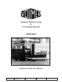
Automatic Thickness Gauge
for
fast running cold strip
VBM 1065
Operation and Service Manual
1065-e4
1065-E4
Rev.02 Seiten:34
erstellt am 1.4.98
Operation
Name: Rietdorf
geprüft am
and Service
Manual
Name:
freigegeben am
VBM
Name:
1065
Bemerkungen
1
measuring
++
controlling
++
recording
++
automation
++
documentation
G
Table of Content
Safety Precautions ........................................................................................... 3
Intended use of this machine ........................................................................... 3
Operation mode selector switch 'Service I/0' .................................................. 4
Design and function ........................................................................................ 4
System ............................................................................................................. 6
Nominal size setting .................................................................................. 7
Types .......................................................................................................... 8
Operation ....................................................................................................... 10
Measurement ................................................................................................. 12
Zero check ............................................................................................... 12
Indication check ....................................................................................... 12
Nominal size and tolerance limits ........................................................... 13
Measurement start and end ...................................................................... 13
Important note for manually traversed gauges .............................................. 13
Continuous checking ..................................................................................... 14
Trouble shooting ............................................................................................ 16
If the gauge measures wrong ................................................................... 16
If the gauge marks the strip ? .................................................................. 17
Maintenance .................................................................................................. 19
Guide rollers ............................................................................................ 19
Measurement frame ................................................................................. 19
G
Repairs ........................................................................................................... 20
To remove the gauge from the support .................................................... 20
To remove the transducers ....................................................................... 20
To remove the guide rollers ..................................................................... 20
To disassemble the housing ..................................................................... 21
To change the Teldix bearing ................................................................... 22
Assembly of the housing ......................................................................... 23
Spares ....................................................................................................... 23
To check the transducer alignment .......................................................... 24
Transducer check ..................................................................................... 24
C-Frame Adjustment ................................................................................ 25
Transducer installation ............................................................................ 26
To check the transducer position ............................................................. 27
Installation ..................................................................................................... 28
Levelling .................................................................................................. 29
Passline adjustment ................................................................................. 29
Inclination of the gauge head to the strip surface ................................... 30
Pneumatic guide rollers and cardan supension (pn/ka) ........................... 30
Spring suspended upper guide rollers without ka-suspension ................ 31
Pneumatic guide rollers (pn) ................................................................... 32
Strip Breakings .............................................................................................. 33
Shear block replacement at vertical guide aside the gauge (PV-S) ......... 33
Shear block replacement at vertical guide behind the gauge (PV-B) ..... 34
2
VBM 1065
Operation and Service Manual
1065-E4
FRIEDRICH VOLLMER Feinmeßgerätebau GMBH, D-58093 Hagen, Verbandsstraße 60, ) +49 2334/507-0, Fax +49 2334/53015
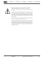
Safety Precautions, please read carefully!
This manual has to be handed to the machine operator, and one copy must
be permanently available to operator and service personnel.
Nobody is allowed to work on or with this gauge, before he has read and
understood this manual. Feel free to call the Vollmer company in case of
any questions (phone +49 2334 507 0).
Warning , Crushing Hazard !This gauge has a hydraulic traverse unit. It has
to be switched to the mode 'Service I', before anybody enters the danger
zone. When operating in the standard mode ('Service 0') the gauge might
rush back or forward unexpected and uncontrollable.
The warning sign "Crushing Hazard ...." which was sent with the gauge
must be installed on a sensible and well visible position after the machine
was installed. Contact the manager in charge for safety in the production
department for installation of the sign. The sign 'Somebody is working on
the gauge...' must lay in the electronic cabinet, so that it is always at hand to
be hung up onto the service switch or close to it.
We care about
your health.
Hands or fingers which are put into the vertical guide behind the gauge or
into the slidebase below the gauge, might get caught and heavily injured if
the gauge head moves up/down or is traversed.
Especially if
you have many
years of professional
experience,
you will be a
Good example
for younger
colleagues
The pneumatic vertical guide and pneumatically operated guide rollers might
cause injuries on hands and fingers. In case of a pressure drop, the vertical
guide with the gauge head might leap up. Under certain conditions, the guide
rollers might close the gap unexpectedly. Therefore the pneumatic system
must be depressurized before anybody starts to work on the gauge.
Please follow
the safety
precautions.
The aluminium gauge head might get hot. Therefore check the temperature
before trying to handle the gauge head. The gauge head is heavy (up to 30
kgs). Therefore get a secure footing and if possible work with two persons
when you have to handle the gauge head without lifting device.
If the gauge head is operated automatically or semiautomatically, the documentation contains a description of the control program for this application. Nobody is allowed to work on the gauge unless he knows the control
program sequences. For your own safety, please make sure to get familiar
with the control program sequences before you start to work on the gauge !
Intended use of this machine
This gauge must be used exclusively for the measurement of cold strip. It
must be firmly installed in its intended position and electrically, electronically, hydraulically and pneumatically connected as intended by the Vollmer company. Any alteration might cause severe damage.
1065-E4
Operation and Service Manual
VBM 1065
3
measuring
++
controlling
++
recording
++
automation
++
documentation
Operation mode selector switch 'Service I/0'
The electronic cabinet for this gauge contains a selector switch labelled
'Service I/0'.
'Service 0' is the position for the normal operation mode in which the gauge
is traversed back and forward automatically. If e.g. when the strip tension
breaks down or when the strip moves laterally the gauge head is traversed
off the strip into its rear limit position with double speed. Danger: Crushing
Hazard! Nobody is allowed in the danger zone as long as the system in the
'Service 0' mode.
When switching to 'Service 1', hang up the warning sign 'Somebody is working
on the gauge...' onto the service switch or close to it.
'Service I' is the position for service operation. The gauge head can only be
traversed by inching service by manual controls in the operator's desk. The
automatic traverse controlling is switched off, so that the gauge will not
move automatically. Caution: crushing hazard for hands and fingers! Do
not put hands or fingers into the vertical guide or the slidebase while the
gauge head is moving.
4
VBM 1065
Operation and Service Manual
1065-E4
FRIEDRICH VOLLMER Feinmeßgerätebau GMBH, D-58093 Hagen, Verbandsstraße 60, ) +49 2334/507-0, Fax +49 2334/53015
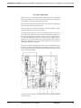
Design and function
The VBM 1065 (2065/2565) is designed to measure strip thickness on high
quality strip in fast running cold rolling mills. The gauge measures the passing
material continuously in its measurement mouth which has a depth of 100
(200/250) mm.
The strip passes the C-shaped thickness measurement frame with two thickness
feelers which are measuring the passing strip simultaneously from the top
and from the bottom. Due to strip thickness changes, the transducer tips are
pushed apart or come closer. The transducer tips are crowned and polished
diamonds, which do not leave any marks on the strip.
Each transducer has a differential transformer at its rear end. The movable
core of this transformer is connected to the measurement tip which is sliding on the strip surface. In this way any movement of the measurement tip
is measured inductively.
All changes within the two transducers are passed to a VMF measurement
amplifier, where they are added (sum measurement). The amplifier indicates a measurement result as deviation from zero, i.e. the difference to the
preset nominal size. Depending on the type of the gauge, there are several
ways for electronic or mechanical nominal size setting, so that the measurement amplifier indicates 0 when the measured strip thickness matches the
nominal thickness.
The C-shaped measurement frame in the VBM 1065 gauge has an extremely low temperature extension. This leads to an optimum reproducibility of
the measurement results. The gauge head is held in the passline by a spring
suspended and pneumatically operated vertical guiding. Guide rollers hold
it always parallel to the strip surface.
Amplifier measurement data can be used as signal for controlling and for
quality monitoring documentation according to ISO 9000. It is available on
two analog voltage outputs. Some VMF amplifiers do additionally provide
digital data outputs.
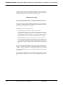
M
V
B
12345678901234567890123
12345678901234567890123
S
H
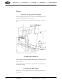
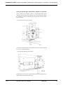
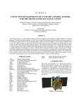
Lateral view on a VBM 1065: The Gauge head M is suspended by vertical guide V.
The vertical guide is traversed in the slidebase S by the hydraulic cylinder H between
the rear limit position and the measurement position on strip B.
1065-E4
Operation and Service Manual
VBM 1065
5
measuring
++
controlling
++
recording
++
automation
++
documentation
System
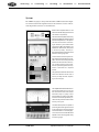
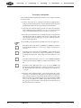
The VBM 1065 gauge is always installed with a VMF measurement amplifier. This measurement amplifier indicates the difference between measured strip thickness and selected nominal size.
Measurement amplifier VMF 311 with
electronic classifier 2S (top) and nominal
DK
size selector FS4 (bottom).
The measurement amplifier continuously
indicates the difference between nominal
and actual strip thickness . The operator
can select the resolution of the analogue indicator by the measurement
range selector MB. Full deflection can
indicate from 1000 microns (.030 ") down
to 10 microns (.0003"). The zero potentiometer NP allows to eliminate small
deviations of the gauge zero.
Tolerance limits can be set by the twodigit switches DK of the electronic classifier. Coloured control lamps indicate
whether the measurement value is in,
over or below tolerance. Such classi-
MB
NP
fiers are optional equipment, their operation is described in a separate
manual.
The (optional) nominal size selector FS4
FS4
shows the selected nominal size in
microns (or steps of 0.0001", depending on the FS4 type).
The amplifierVMF 2000 includes all components described above. It puts out
the measurement data with statistic
evaluation ready for quality control
documentation according to ISO 9000.
Its internal automatic adjustment provides the best possible measurement
accuracy at any time.
The VMF 2000 amplifier is capable of
processing transducer signals of overall
4 mm measurement stroke (instead of
2 mm like the VMF 3/11 and 3/22 types).
Those Transducers and the VMF 2000
amplifier can be used to upgrade nearly
all Vollmer gauges.
6
VBM 1065
Operation and Service Manual
1065-E4
FRIEDRICH VOLLMER Feinmeßgerätebau GMBH, D-58093 Hagen, Verbandsstraße 60, ) +49 2334/507-0, Fax +49 2334/53015
A separate instruction of the measurement amplifier as well as of the positioning device is part of the documentation. They are only mentioned here
because this manual refers to both of them on some pages.
Nominal size setting
If the required material thickness - e.g. 500 µm - is entered as nominal size
and if the measurement is 501 µm, the amplifier will indicate + 1 µm.
So it is possible to stay within the highest sensitivity range of the indicator
no matter of the material thickness. In this range the full deflection of the
indicator covers a range of +/-10 microns.
Nominal size can be set in several ways:
-
mechanically (sum measurement adjustable transducer):
The adjustable transducer is set to the selected nominal size on its micrometer thread. Depending on the model, the nominal size is indicated
by a digital turns counter (mod. Di) or a scale (mod. Scale) or via an
electronic pulse encoder on a separate digital indicator (mod. ME).
-
electronically (sum measurement with two transducers and FS 3/4):
there is no mechanical transducer adjustment, but the measurement value
is electronically compensated for the nominal value by the setting of a
thumb wheel switch, so that the selected nominal size is indicated as
zero.
The electronic adjustment is limited to 1,5 or 3 mm, depending on the transducer type. It can be combined with an adjustable transducer (mod. Di, Scale
or ME) i.e. the upper transducer is mechanically adjusted to one nominal
size, and from that position it can be adjusted electronically to different
nominal sizes.
Depending on the application there are additional control, indicator or data
processing devices which can be connected to the measurement electronics.
1065-E4
Operation and Service Manual
VBM 1065
7
measuring
++
controlling
++
recording
++
automation
++
documentation
Types
According to individual requirements of our customers, Vollmer gauges
are produced in many different types. The gauge card in the documentation
shows the type of your gauge. The following list is a general overview about
the available items:
e.g.: VBM 1065 E/Su/FS4/pn/ka/pV-B/T/K/A0/DAV/AS/BCD-in/BCDout/Hwst 500.
Meaning of the abbreviations:
VBM1065 E:
Electronic strip thickness gauge for high quality strip on fast cold rolling
mills, measurement depth up to 100 mm from the strip edge (Gauges of the
types 2065 and 2565 have a measurement depth of 200 resp. 250 mm but are
designed in the same way).
Su:
Measurement by 2 transducers in sum; accurate measurement values even
in case of strip vibration.
FS4:
4 digit nominal size selection by thumbwheel switch
pn:
The upper guide rollers are pneumatically pushed down onto the strip (i.e.
the gap between upper and lower guide rollers is closed) when the gauge is
in On Strip position (measuring position).
ka:
With this cardanic suspension the gauge measures precisely, even when the
strip lies in a hollow shape.
pV-B:
Pneumatically operated vertical guiding, passline adjustment by pressure
variation in the pneumatic cylinder; guiding is installed behind (not beside)
the gauge head.
pV-S:
same as pV-B, only that the vertical guiding is installed behind (not beside)
the gauge head.
T:
Heating elements in the gauge head for keeping a constant temperature, against
long-term drift because of heat coming from the strip into the gauge.
K:
Air cooling of the transducer's measurement tips, against short-term drift if
the measurement tips are heated by the strip.
A0:
Electronic adjustment system, which works when the gauge is in its rear
8
VBM 1065
Operation and Service Manual
1065-E4
FRIEDRICH VOLLMER Feinmeßgerätebau GMBH, D-58093 Hagen, Verbandsstraße 60, ) +49 2334/507-0, Fax +49 2334/53015
limit position. The gauge is set to nominal size zero. Then the amplifier
adjusts itself to zero. This procedure is started either by pressing a key or by
time automatic, available only in combination with VMF 3/22 or VMF 2000.
DAV:
The diamond measurement tips of the two transducers are pneumatically
pulled apart when the gauge is traversed, in order not to damage them at the
strip edge. For measurement of wavy strip or vibrating strip the measurement pressure can be pneumatically increased to prevent the measurement
tips from losing contact to the surface.
AS:
Automatic symmetry adjustment, the transducer tips can be moved up/down
pneumatically instead of manual manipulation
BCD-In:
External nominal size input, potential-free contact via opto-couplers, BCD
coded
BCD-Out:
External nominal size output, potential-free contact via opto-couplers, BCD
coded
Hwst 500:
Hydraulic traverse unit consisting of a control unit and a slidebase, stroke
of the hydraulic cylinder is 500 mm
1065-E4
Operation and Service Manual
VBM 1065
9
measuring
++
controlling
++
recording
++
automation
++
documentation
Operation
Depending on the application the gauge operates manually or automatically controlled.
During manual operation the most important thing is, to move the gauge off
the strip before the strip end runs through it.
If - in automatic mode - the gauge is set to „On Strip“, it moves automatically to the measurement position. If it is ready to measure, the measurement
electronic puts out a start signal.
Mostly the measurement position is detected by a light barrier at the front
of the measurement head. As soon as the light beam is interrupted when the
gauge head is crossing the strip edge, a timer starts which stops the movement after a preselected time (set during commissioning).
Instead of the timer it is also possible to use a pulse encoder for the controlling of the measurement depth. In that case the measurement depth can be
set by a decade switch and the selected measurement depth is digitally indicated.
“Off strip“ makes the gauge moving back to its rear position immediately,
independent of the actual position.
Before the strip end passes through and would damage the gauge, an external signal is given and the gauge automatically moves off the strip. Various
electronic interlocks are possible to avoid damage. For example a strip tension breakdown may be the trigger for moving back the gauge. Or the gauge
moves only on strip and remains there, if a certain rolling speed is exceeded. Each gauge is provided with a limit switch. If the strip reaches too far
into the measurement mouth, the gauge is moved back.
While the gauge moves forward or backwards, the DAV (Diamond Lifting
Device) operates automatically. The transducers are lifted in order to avoid
the diamonds scratching over the strip edge or click together when the gauge
moves back. The process is specified in the records of PLC (if the gauge has
an automatic traversing device).
In the "Service I" mode the gauge head can be hydraulically moved back
and forward by inching operation. In this mode the compressed air supply is
switched off, i.e. the pneumatic guide rollers cannot be closed and the DAV
is not operational.
When pressing the A0 button (option for an automatically traversed gauge),
the gauge is traversed to its rear limit position and is automatically set to
zero. After the amplifier has adjusted itself to zero the gauge is traversed
On Strip again.
10
VBM 1065
Operation and Service Manual
1065-E4
FRIEDRICH VOLLMER Feinmeßgerätebau GMBH, D-58093 Hagen, Verbandsstraße 60, ) +49 2334/507-0, Fax +49 2334/53015
After pressing "Insert Adjustment Plate / Calibrate" (optional function) the
gauge will set itself to a preset nominal size. Then the adjustment plate with
integrated slip gauge is pneumatically inserted between the guide rollers
and the transducer tips. This function is only enabled as long as the gauge is
in its rear limit position and switched to 'Service I'. If the gauge measures
correctly, the indication is near zero. If not, check the symmetry adjustment.
1065-E4
Operation and Service Manual
VBM 1065
11
measuring
++
controlling
++
recording
++
automation
++
documentation
Measurement
Zero check
Zero checking should be performed regularly. Set the gauge to nominal size
zero and check the VMF indication. It should be zero. Minor deviations can
be eliminated by the VMF 3/22 zero potentiometer or by the Master key of
the VMF 2000.
Then operate the DAV or put a thin piece of material between the transducer tips and take it out again. The indication must return to zero. If not, check
the gauge (see section "Trouble shooting").
Indication check
If the previous test shows a constant zero, check the gauge measurement by
means of an adjustment plate with integrated slip gauge (optional addition).
This test should be made regularly, especially when rolling with tight tolerances. The gauge must be in its rear limit position and in the "Service I' position.
At first set the nominal size to the thickness of the slip gauge and turn off
the working pressure of the pneumatic guide rollers. Then insert the slip
gauge plate between the guide rollers as shown in the sketch. When the transducer
tips measure the integrated slip gauge, then the indication should be very
close to zero (+/- 0,5 µm). If not check the entire gauge adjustment.
To check the gauge with an adjustment plate: The thick part in the center of the plate
is pointing downwards. Please follow the safety precautions and set the gauge into
the 'Service I' mode, before somebody is allowed to go close to the gauge into the
danger zone.
Do not forget to turn back on the working pressure for the pneumatic
guide rollers after this test.
12
VBM 1065
Operation and Service Manual
1065-E4
FRIEDRICH VOLLMER Feinmeßgerätebau GMBH, D-58093 Hagen, Verbandsstraße 60, ) +49 2334/507-0, Fax +49 2334/53015
Nominal size and tolerance limits
After the zero check, nominal strip thickness is set by the FS4 thumb wheel
switch or by the (optional) positioning device. Then press ‘Nominal Size
Start’ and the stepper motor will set the upper transducer to the new nominal size.
Tolerance limits can be entered into the electronic classifier 2S or 4S (optional item, see separate instructions) or by then keys of the VMF 2000.
Measurement start and end
For measurement the gauge is forwarded to the "on strip" position. If it has
a DAV, the transducer tips are then lifted automatically until the gauge is in
measurement position.
Measurement amplifier and classifier do now indicate the difference between nominal and actual size and whether the measurement value is in or
below tolerance, or if it is exceeding the upper limit.
Important note for manually traversed gauges
The strip end must never pass through the gauge, as it will cause serious damage.
1065-E4
Operation and Service Manual
VBM 1065
G
Please do always move the gauge off the strip before the strip tension is switched off!
13
measuring
++
controlling
++
recording
++
automation
++
documentation
Continuous checking
In between the service intervals, it is recommended to check the gauge regularly:
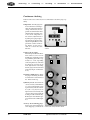
Temperature: After the gauge was
traversed into the rear limit position, the temperature must not
change. That means, the temperature deviation indicator TD
should remain constantly close
to zero. If the temperature is
not constant, adjust the heater
by setting a new gauge temperature with the two knobs S. Ideally the Lamp H (Heater) at the
pneumatic cabinet is indicating, that the ‘on’ and ‘off’ periods are of about the same
duration.
Compressed air supply:
Permanent pressure for the Pneumatic rollers is set to 1 bar on
the PR gauge. Working pressure
for pneumatic guide rollers (optional) is 3 - 5 bar, depending
on the strip material, controlled
by a magnetic valve that opens
if the light barrier is detecting
that the gauge is in measurement
position (lamp P = ‘In Position’
is on).
Transducer lifting device: When
the gauge is traversing, the thickness indicator needle must be at
the ‘minus’ limit stop.
Symmetry check: Switch into the
‘Service I’ mode, set nominal size
to 0, move both transducer tips
up and down, (indication has to
be 0 µm +/-0,5 µm). In case of
tight tolerances check daily, otherwise weekly). Gauges with AS
do this procedure automatically.
Both ways are described in a separate manual for the VMF amplifier.
Accuracy check with slip gauge:
Set the gauge to the nominal size
of the slip gauge, and insert the
14
VBM 1065
TD
S
Temperature control device in the electronic
cabinet
P
H
PR
PV
Lateral view of the pneumatic cabinet
Operation and Service Manual
1065-E4
FRIEDRICH VOLLMER Feinmeßgerätebau GMBH, D-58093 Hagen, Verbandsstraße 60, ) +49 2334/507-0, Fax +49 2334/53015
adjustment plate with integrated slip gauge between the transducer tips.
The indication should be zero. In case of tight tolerances check daily,
otherwise weekly.
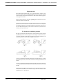
Transducer position to the strip: The transducers must stand perpendicular to the strip. Lift or remove the upper guide rollers and put the test
plate onto the lower guide rollers. Tip it to both sides as well as to the
front and to the back (see sketch 1 through 4). The display may only
deflect to the + side. If not, check the whole gauge. This check is recommended after a strip breaking or other hard treatment.
For your convenience, the Vollmer company offers a special adjustment
plate with an integrated slip gauge, which is individually selected to match
the thickness of that strip which is usually rolled on your mill (see picture under 'Measurement / Indication Check'.
Guide rollers: Check for easy rotation.
Passline: Check the correct height of the gauge to the strip
Safety Precautions
Nobody must work on the gauge unless it has been switched into the 'Service I' mode.
This mode makes sure, that the gauge will not be automatically traversed and the
pneumatic guide rollers will not close unexpectedly.
Caution: Crushing hazard ! Never traverse the gauge as long as somebody is in the
danger zone ! The hydraulic cylinder which is traversing the gauge has great power.
1065-E4
Operation and Service Manual
VBM 1065
15
measuring
++
controlling
++
recording
++
automation
++
documentation
Trouble shooting
If the gauge measures wrong
m Wrong point remeasured ?
Cross profile strip thickness varies in many cases. If the gauge is checked,
strip thickness must be measured at the same distance from the edge as
the transducers have measured.
ð Check the strip thickness at correct edge distance
m Transducers dirty ?
In a very dirty environment, the rams of the transducers sometimes get
too sticky, so that they do not shut completely. If the gauge is then set to
zero, the indication of a following measurement is too low. After cleaning, any transducer ram should slide easy in its bushing or bearing for a
quite long period of time.
ð Increase cleaning frequency
m Transducers clamped too hard?
If the clamp screws in the C-frame are tightened too hard, they possibly
distort the transducer housing which increases the friction in the ram
guiding.
ð Loosen the clamp screw and re-tighten with moderate force
m Oil in the flexible cable protection hose?
The oil increases the friction of the ram guide bushing or ball bearing. In
that case the transducers cannot continuously keep contact to a vibrating strip. The measurement then indicates “too thick”. Much oil in the
protection hose does additionally choke the diamond lifting. Drain the
oil from through the brass drain screw (10 mm spanner) at the transducers cable entry. Remove the Allen bolt from the white DAV plastic connector peace and blow in compressed air (see extra DAV instruction manual).
ð Clean the transducer and possibly improve compressed air quality.
m Gauge zero not constant?
If the screws, which connect the measurement tip with the guide ram,
are not tight, the measurement ram might move against the guide ram.
If, for example, DAV was activated or material was placed between the
transducers and then removed, the zero point changes. The indication is
incorrect even if the symmetry is correct.
ð Fasten the grub screws in the guide ram (see transducer manual)
m Long-term drift of the zero point?
An integrated heater heats the gauge so that the temperature does not
change whether the gauge is measuring or not. The temperature control
should be adjusted so that the gauge always keeps the same temperature
when it is moved off the strip or when the measurement starts after a
long stop. The temperature should not drift for more than 2°C degrees.
m Short-term drift of zero point?
Can be noticed, if the rolling has been finished and the gauge in its rear
position is directly moved set to nominal size zero without pushing A0.
If then the indication drifts away to + or -,the cooling of the diamonds
does not work correctly. Check, if the small air pipes are not bent. Com-
16
VBM 1065
Operation and Service Manual
1065-E4
FRIEDRICH VOLLMER Feinmeßgerätebau GMBH, D-58093 Hagen, Verbandsstraße 60, ) +49 2334/507-0, Fax +49 2334/53015
ing from the ingoing side of the gauge the jet has to meet exactly the tip
of the transducer. Readjust the cooling at the ‘pneumatic diamond cooling’ valve in the pneumatic cabinet.
ð Connect the air supply correctly or adjust air pressure
(if the display drifts away to minus - increase cooling,
if the display drifts away to plus - reduce it).
m Indication too low?
If the transducers in the C-frame are clamped not tight enough, they might
be shifted in their bore. Gauge zero is then shifted too.
m Indication wrong?
If the fine thread of the upper transducer is defective or worn, the nominal size setting is disturbed.
m Indication wrong?
Check the transducer symmetry by moving up and down both transducer
tips. If the indication does not stay 0
ð Readjust the transducer symmetry
m Additional check for gauges with decade switch (type FS3/FS4): After
symmetry adjustment or after a new transducer was installed, the adjustment of the measurement amplifier to the nominal size selector has
to be checked by a slip gauge. Set the gauge to 0 and insert 500 or 800 µm
slip gauge. Then set the decade switch to 500 (resp. 800) and check, if
the gauge measures zero. If not,
ð adjust the VMF to the nominal size selector switch by the X9 sensitivity
potentiometer (only for VMF 3/11 and 3/22)
m Indication too high ?
Put an adjustment plate onto the lower guide rollers and set the gauge to
zero. Tip the plate it to both sides as well as forward and backward. The
indication should deflect only towards +. If not,
ð check the complete gauge (measurement tips for wear, C-frame for 90°
position and C-frame distortion)
m Indication too high ?
After strip breaking or when the strip end passed through the gauge, the
C-frame is possibly bent. The indication is too high. Check as before
and
ð check the alignment of transducer clamping bores with a 20 mm inspection pin.
If the gauge marks the strip ?
m Diamond with small cracks ?
If hit too hard, the diamonds in the transducer measurement tips might
get tiny ring-shaped cracks, which are hardly visible. Sometimes such
cracks mark the strip
ð Replace the measurement tip
1065-E4
Operation and Service Manual
VBM 1065
17
measuring
++
controlling
++
recording
++
automation
++
documentation
m Diamond broken out?
In case of strip breaking a diamonds might break out of a transducer
measurement tip.
ð Replace the measurement tip
m Roller blocked ?
ð Replace the roller. If the roller surface is not damaged, replace only the
bearings.
18
VBM 1065
Operation and Service Manual
1065-E4
FRIEDRICH VOLLMER Feinmeßgerätebau GMBH, D-58093 Hagen, Verbandsstraße 60, ) +49 2334/507-0, Fax +49 2334/53015
Maintenance
The thickness gauge does not need much maintenance. Only the measurement tips with the diamonds and the guide rollers are subject to wear. The
gauge should be cleaned regularly in order to avoid dirt deposits which might
block movable parts.
Safety Precautions
Nobody must work on the gauge unless it has been switched into the 'Service I' mode.
This mode makes sure, that the gauge will not be automatically traversed and the
pneumatic guide rollers will not close unexpectedly.
Caution: Crushing hazard ! Never traverse the gauge as long as somebody is in the
danger zone !
At least the following points must be checked regularly, even if measurement results and symmetry are correct
Guide rollers
m Clearance?
The rollers have to move freely. They should have only little axial clearance.
Blocking rolls mark the strip.
ð Replace defective rollers
m Deposits on the surface?
Some strip materials tend to leave deposits on the rollers. They cannot
run smooth and might mark the strip.
ð Replace rollers (rework if possible)
m Roller support defective?
On strip, the pneumatic guide rollers are pressed down (working pressure 3-5 bar). Check regularly, if the upper guide rollers move up to
their mechanical limit stop when the compressed air is switched off.
Check the lower guide rollers for parallel adjustment (see under ‘Continuous checking / Transducer position to strip’. The plate indicates if
the rollers are not parallel. This happens very rarely, sometimes after
strip breaking.
ð Replace and or adjust (see under 'Maintenance/Repairs').
Measurement frame
m Easy movable?
The C-frame might get stuck because of large dirt deposits in the gauge
mechanics. The measurement frame must rest against its bottom limit
stop. In that position, the alignment pin must slide easily into the adjustment hole on the left side of the gauge head.
ð Clean the gauge
1065-E4
Operation and Service Manual
VBM 1065
19
measuring
++
controlling
++
recording
++
automation
++
documentation
Repairs
To remove the gauge from the support
First undo all plug connections at the connector board behind the gauge and
remove the plugs and sockets from the board.
Now loosen clamping screw 57 and pull the gauge out of the rotation bearing.
At all types the rotation bearing is clamped with screw 57.
To remove the transducers
First unscrew the lid from the housing and then loosen the transducer clamps
in the C-frame by inserting a spanner through holes A in the front of the
gauge housing.
The housing is open at its bottom side, only the small cable guide bar at the
rear has to be opened.
To remove the guide rollers
Remove both screws 36 and then take off the roller support with its two
guide rollers.
20
VBM 1065
Operation and Service Manual
1065-E4
FRIEDRICH VOLLMER Feinmeßgerätebau GMBH, D-58093 Hagen, Verbandsstraße 60, ) +49 2334/507-0, Fax +49 2334/53015
To disassemble the housing
Type „ka/PV-B“ requires to remove the right side arm of the „ka“ device
(see sketch ka/PV-B) before the gauge head is ready to be disassembled.
First turn out grub screw 5 and then loosen clamp screw 20 on both sides of
the gauge head. Then remove the two screws 19 and take off the right arm of
the „ka“ device.
1065-E4
Operation and Service Manual
VBM 1065
21
measuring
++
controlling
++
recording
++
automation
++
documentation
Now remove the eight screws 37 (see sketch PV-B) and take off the right
side of the housing, eventually give a push with a plastic hammer. Do not
remove the left side of the gauge.
If there was any wrong measurement result, e.g. after a strip break, the alignment
of the transducer clamps must be checked with an inspection bolt (available
at Vollmer). It has easily to slide through both clamps. If not, get the Cframe aligned at Vollmer.
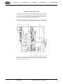
To change the Teldix bearing
The Teldix bearing needs only to be replaced if it is broken.
First remove the right side panel and then spring set screw 101-16 together
with its spring and pressure ram.
When all five screws 1111 are removed from below, the Teldix spring can
be pulled out to the side. Now the C-frame with the middle piece of the
bearing can be taken off. The middle piece is connected to the C-frame by
screw 1110.
VBM 1065 sectional view: 5 screws 1111 clamp the Teldix-bearing.
22
VBM 1065
Operation and Service Manual
1065-E4
FRIEDRICH VOLLMER Feinmeßgerätebau GMBH, D-58093 Hagen, Verbandsstraße 60, ) +49 2334/507-0, Fax +49 2334/53015
When re-installing the bearing, stand the gauge body upright and rotate the
Teldix spring in a position, where the C-frame does not hang down at its
front but rests in a levelled position when the transducers are installed (loosen
all clamps screws and turn the whole Teldix spring).
Insert the locking pin in its adjustment hole B before tightening the clamp
screws for the Teldix spring, in order to ensure that the C-frame is exactly
installed into its former position.
The set screw 101-16 should be adjusted to its former position, where it
puts a firm pressure under the C-frame against limit stop 32.
Assembly of the housing
First insert the side panel, then the lower guide rollers and afterwards the
transducers. The upper guide rollers can only be reinstalled after the transducer position has been corrected and the levelling of the C-frame was checked.
Spares
Each component of the VBM 1065 is identified by the position number and
the drawing number.
Example: A guide roller of the VBM 1065 is part 9 in drawing W80/172
Note
For spare parts orders please use the complete drawings in the documentation and
not the details in this manual.
1065-E4
Operation and Service Manual
VBM 1065
23
measuring
++
controlling
++
recording
++
automation
++
documentation
To check the transducer alignment
If there was any wrong measurement result, e.g. after a strip break, the alignment
of the transducer clamps should be checked with an inspection bolt (available from Vollmer). It must slide easily through the two clamps. If not, have
the C-frame aligned at Vollmer, or replace it.
Transducer check
This is just a basic check of the transducer function. Please read the separate transducer service manual for service and repair.
m Ram easy movable ?
The transducer rams must be easy to be pushed in and spring back immediately.
m Measurement tips worn or damaged?
If the measurement result of the slip gauge plate is not 0, but the other
checks are all right, remove the transducers and check the measurement
tips:
m Diamonds worn?
The diamonds should be crowned to achieve accurate measurement results. Worn diamonds with flat spots may cause measurement errors.
ð Replace and possibly get the old diamonds reworked
m Broken diamonds?
Cause incorrect measurement results and mark the strip
ð Replace
m Measurement tips with broken-out diamonds? (after strip breaking or
when the strip end has passed through the gauge)
ð Replace
m Micrometer thread damaged?
Worn micrometer threads cause measurement errors. Check: Set the transducer to zero, select a nominal size and insert the correspondent slip
gauge. Try with several slip gauges. The indication has to be very close
to zero. If not,
ð send the transducer to Vollmer for repair without trying to repair the
thread by yourself.
24
VBM 1065
Operation and Service Manual
1065-E4
FRIEDRICH VOLLMER Feinmeßgerätebau GMBH, D-58093 Hagen, Verbandsstraße 60, ) +49 2334/507-0, Fax +49 2334/53015
C-Frame Adjustment
Insert setscrew 101-16 with spring and ram and adjust it to its old position
where it puts a firm pressure on the C-frame against limit stop 32. The front
of the C-frame can be lifted against a firm pressure.
Then insert the supplied locking bolt from the left side into the drill trough
both sides of the housing and the C-frame.
Now the C-frame is levelled in the housing, so that the transducer clamps
stand perpendicular to the lower guide rollers.
Then adjust limit stop nut 32: Loosen the locking nut and the screw nut 32
easy against part 19 and lock it again. If now the locking bolt is pulled out,
the front of the C-frame may not move down. The screw is adjusted correctly, when the VMF indication does not change when the alignment pin is
pulled off. Screw 34 forms a limit stop for the upward movement of the Cframe. It is adjusted so that the front of the C-frame can move up about 3
millimetres from the level position.
The C-frame is hold revelled by spring set screw 101-16 against nut 32. The
C-frame can only move up as protection against damage. Screw 101-16 with
its spring suspension puts an adjustable pressure under the C-frame in order
to prevent it from swinging.
Hole B, nut 32, pin 34 and setscrew 101-16 determine the C-frame position inside the
measurement head.
1065-E4
Operation and Service Manual
VBM 1065
25
measuring
++
controlling
++
recording
++
automation
++
documentation
Transducer installation
After cleaning or diamond changing the transducers can easily be reinstalled
into the C-frame:
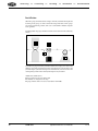
set the C-frame into the 90° position by inserting the supplied adjustment pin into the adjustment hole J. Put the adjustment plate P into the
measurement mouth with the step pointing towards the bottom.
connect the lower transducer B (no gear wheel) to cable/socket X2 switch
on the VMF measurement amplifier, select the 1000 µm measurement
range, set the FS4 nominal size selector (if there is one) to zero
E
¨
¨
¨
¨
insert the lower transducer into its holding and push it up against the
adjustment plate until the amplifier indicates the required value. That
value depends on the type of the gauge (see gauge card in the documentation) and the application:
We marked the paragraph with the optimum values for your application:
Transducers with 1 mm stroke (20-MUBE-0/20 MOBE-0) and measurement amplifier VMF 3/11 or 3/22 or 2000: clamp lower transducer at
+500 µm
Transducers with 1 mm stroke (two 20-MUBE-0) and measurement amplifier VMF 3/11 or 3/22 or 2000: clamp lower transducer at +800 µm. If
measuring only strip below 1 mm, clamp the lower transducer at +500
µm
Transducers with 2 mm stroke (series -90 or -92, 20-MUBE/20 MOBE),
and measurement amplifier VMF 2000: clamp lower transducer at +1000
µm
Transducers with 2 mm stroke (series -90 or -92, two 20-MUBE), and
measurement amplifier VMF 2000: clamp lower transducer at +1500
µm. If measuring only strip below 1 mm, clamp the lower transducer at
+1000 µm
Then take off the adjustment plate, select measurement range 10 µm,
connect the second transducer and push it into the upper hole against the
lower transducer until the measurement amplifier indicates nearly zero.
Minor deviations can be eliminated by the zero point potentiometer (VMF
3/22 + 3/22) or the Master key (VMF 3/2000). Before inserting, screw
the upper part of the transducer clockwise down to the limit stop, and
then turn it back for one full turn.
26
VBM 1065
Operation and Service Manual
1065-E4
FRIEDRICH VOLLMER Feinmeßgerätebau GMBH, D-58093 Hagen, Verbandsstraße 60, ) +49 2334/507-0, Fax +49 2334/53015
Important note
With measurement amplifiers VMF 3/11 and VMF 3/22 please do always use a
transducer together with its own extension cable, which was individually adjusted
to the transducer measurement characteristics. With another cable the gauge accuracy might be affected.
Please do always check the transducer symmetry after a transducer was re-inserted (see separate VMF manual)
If there was any soldering done on the cable or the transducer coil, check the compensation resistor in the transducer cable connector as well as the VMF phase
and sensitivity adjustment. On gauging systems with transducers of the ../90 series and VMF 3/2000 amplifiers, parts of these procedures are performed automatically (see separate manual).
To check the transducer position
The upper guide rollers must be lifted or removed for this check. Put the
adjustment plate onto the lower guide rollers and tip it to all four directions,
see sketch 1 through 4. The indicator must be deflected at any time exclusively towards the + side. If not, the gauge needs service:
If “minus” is indicated when the plate is tilted towards one side (sketches 1+2), either
the transducer tips are worn, the C-frame is distorted or the lower guide rollers are not
parallel.
If “minus” is indicated when the plate is tilted towards the front or the back sketches 3
+ 4), it is also possible, that the 90°-position of measurement frame was not correctly
adjusted.
If a diamond is not supported exactly in its center, the indication deflects to
minus. In this seldom case the mistake changes with the transducer when
rotating it by 90 or 180 degrees.
1065-E4
Operation and Service Manual
VBM 1065
27
measuring
++
controlling
++
recording
++
automation
++
documentation
Installation
When the gauge is installed into an inspection line, installation height and
levelling of the gauge are derived from the inspection table. If the gauge
was removed from its position, take care to reinstall the slidebase angular
to the passline.
In rolling mills the gauge should be installed as described in the following
sketch:
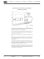
W
G
H
U
K
If possible, the gauge should be positioned between the roll gap (mill = W) and the
deflector roll U. Base and the bracket K are so high that they lie under the strip by the
"passline height" H (see data drawing in the documentation). Here the stroke of the
vertical guiding is able to follow the expected range of strip movement.
Additional conditions are:
l base parallel to roll axes in the mill
l slidebase rectangular to the strip
l gauge must be able to traverse towards the roll middle
28
VBM 1065
Operation and Service Manual
1065-E4
FRIEDRICH VOLLMER Feinmeßgerätebau GMBH, D-58093 Hagen, Verbandsstraße 60, ) +49 2334/507-0, Fax +49 2334/53015
Levelling
If the strip does not run horizontally the gauge head can be turned: Loosen
clamp screw 57 at the rear of the gauge. Lift the gauge at the front, adjust it
to the strip passline angle and clamp it again.
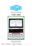
Passline adjustment
The gauge is suspended by pressure springs in the vertical guide which push
it up. There is no need to change the spring adjustment done at Vollmer. A
pneumatic cylinder pushes the gauge down into the passline height. Adjust
the height of the gauge pneumatically, so that the bottom guide rollers are
just turned by the strip when the gauge is moved onto the strip. The strip
should not pull the gauge down.
The lower limit stop of the vertical guide is adjusted to the lowest possible
passline (see sketch ka/PV-B).
Push the gauge head pneumatically down to the lowest possible passline.
Now fasten sliding part 13 in this position by the two grub screws 43 and 42
beginning at the top side. Working pressure of the pneumatic cylinder should
not exceed 3 bar, in order to ensure that the gauge is able to follow the strip
movements easy enough.
Items for levelling and passline adjustment. Please read the text for details.
1065-E4
Operation and Service Manual
VBM 1065
29
measuring
++
controlling
++
recording
++
automation
++
documentation
Inclination of the gauge head to the strip surface
Pneumatic guide rollers and cardan supension (pn/ka)
Gauges with „pn/ka“ equipment hold on to the strip by pneumatic guide
rollers. They incline within the „ka“-suspension, so that the transducers stand
always perpendicular to the strip surface. There are two versions:
- pn/ka with the vertical guide aside the gauge ka/PV-S)
The inclination of the gauge head within the ka-suspension can be adjusted by nut 36.
The two set screws 38 form the limit stops for the inclination movements of the measurement head, and they can also be used to lock the inclination movements.
- pn/ka with vertical guide behind the gauge (ka/PV-B)
The inclination is adjusted at grub screw 5 (see sketch on previous page).
The limit stop (and lock) within the „ka“-device is situated at the opposite
side of the gauge head.
30
VBM 1065
Operation and Service Manual
1065-E4
FRIEDRICH VOLLMER Feinmeßgerätebau GMBH, D-58093 Hagen, Verbandsstraße 60, ) +49 2334/507-0, Fax +49 2334/53015
Spring suspended upper guide rollers without ka-suspension
Gauges of this version (without „pn/ka“) are used at mills with very flat
strip. Here the inclination of the gauge head is adjusted only once during
the installation in order to adjust the gauge head parallel to the sled. There
are two versions:
- vertical guide aside the gauge (PV-S)
The inclination of the gauge head can be adjusted by the two set screws 66 when the
four screws 51 have been loosened.
- vertical guide behind the gauge (PV-B)
By tightening the two grub screws C right and left below the rotation bearing it is possible to lift the front of the gauge head a little.
1065-E4
Operation and Service Manual
VBM 1065
31
measuring
++
controlling
++
recording
++
automation
++
documentation
Pneumatic guide rollers (pn)
The upper guide rollers are pressed down pneumatically. Working pressure
is between 3 and 5 bar, depending on the kind of material which is being
measured. Pressure is set by the valve 'Pneumatic Guide Rollers' at the pneumatic
cabinet (see section 'Guide Rollers' under 'Maintenance').
If their pneumatic cylinder is not under pressure, the upper rollers should
be easy to move up by hand and should be pushed down by spring pressure.
The two nuts 31 form the limit stop for the upper guide rollers: Remove the lid of the
gauge housing and turn the nuts clockwise until an even gap of 1 mm occurs between
the upper and the lower guide rollers.
32
VBM 1065
Operation and Service Manual
1065-E4
FRIEDRICH VOLLMER Feinmeßgerätebau GMBH, D-58093 Hagen, Verbandsstraße 60, ) +49 2334/507-0, Fax +49 2334/53015
Strip Breakings
The gauge support has got a breaking point below their vertical guiding in
order to protect gauge and support in case of strip breaks. The shear blocks
from cast material are easy to replace.
Replacement of the shear block at vertical guide aside the gauge (PV-S)
Remove screw 60 and slide out part 8 laterally. Now replace the remains of the old
shear block against a new one.
After that unscrew the two screws F and lift the housing of the vertical guide for about
50 millimetres. Now the other part of the shear block is accessible.
1065-E4
Operation and Service Manual
VBM 1065
33
measuring
++
controlling
++
recording
++
automation
++
documentation
Replacement of the shear block at vertical guide
behind the gauge (PV-B)
At gauges without „ka“ device at first the two grub screws C have to be loosened far
enough in order to take all load off them. After the shear block was replaced, the
inclination of the gauge head has to be newly adjusted.
Now unscrew the three screws D from both sides of the vertical guide, but remove
screw E only at one side. Now take off the side panels of the vertical guide and remove the upper part of the shear block.
The bottom screws of the shear blocks are accessible from the bottom side of the
sled.
Please set the top transducer mechanically to zero after each strip break
and check the zero point. If it has not changed, the measurement can continue immediately.
If the gauge does not indicate 0 after the top transducer has been set to the
zero position, set the measurement amplifier to zero and check the symmetry. Check a sample, which is integrated into the test plate (available at Vollmer).
If these points are all right, measurement can go on.
If the symmetry is disturbed, or if the measurement does not indicate the
exact thickness of the sample, check the whole gauge. Take special care of
the diamonds, the easy movement of the transducer rams and the alignment
of the transducer holes in the C-frame.
34
VBM 1065
Operation and Service Manual
1065-E4