1
EH72 FI
SERVICE INFORMATION
PREFACE
This manual covers the service information, trouble shooting procedures and so on of
EH72 FI (Fuel injection) engine.
Careful observance of the instructions given herein will result in better, safer and faster
service work.
For more detailed instructions of disassembling and reassembling procedures, please
refer to the service manual for EH63, 64, 65 and 72.
CONTENTS
Section
Title
Page
1. SPECIFICATIONS. . . . . . . . . . . . . . . . . . . . . . . . . . . . . . . . . . . . . . . . . . . . . . . . . . . . . . . . . . . . . 1
2. FEATURES . . . . . . . . . . . . . . . . . . . . . . . . . . . . . . . . . . . . . . . . . . . . . . . . . . . . . . . . . . . . . . . . . 2
3. DESCRIPTION OF FUEL SYSTEM. . . . . . . . . . . . . . . . . . . . . . . . . . . . . . . . . . . . . . . . . . . . . . . . . 3
4. DISASSEMBLY AND REASSEMBLY. . . . . . . . . . . . . . . . . . . . . . . . . . . . . . . . . . . . . . . . . . . . . . . 4
4-1 PREPARATIONS AND SUGGESTIONS. . . . . . . . . . . . . . . . . . . . . . . . . . . . . . . . . . . . . . . . . . . . . . . 4
4-2 SPECIAL TOOLS. . . . . . . . . . . . . . . . . . . . . . . . . . . . . . . . . . . . . . . . . . . . . . . . . . . . . . . . . . . . . . . . . 4
4-3 DISASSEMBLY PROCEDURES (DIFFERENCE). . . . . . . . . . . . . . . . . . . . . . . . . . . . . . . . . . . . . . . . 5
4-4 REASSEMBLY PROCEDURES (DIFFERENCE). . . . . . . . . . . . . . . . . . . . . . . . . . . . . . . . . . . . . . . . 9
4-5 BREAK-IN OPERATION. . . . . . . . . . . . . . . . . . . . . . . . . . . . . . . . . . . . . . . . . . . . . . . . . . . . . . . . . . 14
5. DIAGRAM. . . . . . . . . . . . . . . . . . . . . . . . . . . . . . . . . . . . . . . . . . . . . . . . . . . . . . . . . . . . . . . . . . 15
6. THROTTLE BODY. . . . . . . . . . . . . . . . . . . . . . . . . . . . . . . . . . . . . . . . . . . . . . . . . . . . . . . . . . . . 16
6-1 SPECIFICATIONS. . . . . . . . . . . . . . . . . . . . . . . . . . . . . . . . . . . . . . . . . . . . . . . . . . . . . . . . . . . . . . . 16
6-2 FUNCTIONS AND CONSTRUCTION. . . . . . . . . . . . . . . . . . . . . . . . . . . . . . . . . . . . . . . . . . . . . . . . 16
6-3 FUEL SYSTEM OUTLINE. . . . . . . . . . . . . . . . . . . . . . . . . . . . . . . . . . . . . . . . . . . . . . . . . . . . . . . . . 17
6-4 FUEL SYSTEM TESTING AND DIAGNOSIS. . . . . . . . . . . . . . . . . . . . . . . . . . . . . . . . . . . . . . . . . . 17
7. INSTALLATION. . . . . . . . . . . . . . . . . . . . . . . . . . . . . . . . . . . . . . . . . . . . . . . . . . . . . . . . . . . . . . 18
7-1 INSTALLING . . . . . . . . . . . . . . . . . . . . . . . . . . . . . . . . . . . . . . . . . . . . . . . . . . . . . . . . . . . . . . . . . . . 18
7-2 VENTILATION . . . . . . . . . . . . . . . . . . . . . . . . . . . . . . . . . . . . . . . . . . . . . . . . . . . . . . . . . . . . . . . . . 18
7-3 EXHAUST GAS DISCHARGE . . . . . . . . . . . . . . . . . . . . . . . . . . . . . . . . . . . . . . . . . . . . . . . . . . . . . 18
7-4 FUEL SYSTEM . . . . . . . . . . . . . . . . . . . . . . . . . . . . . . . . . . . . . . . . . . . . . . . . . . . . . . . . . . . . . . . . . 19
7-5 POWER TRANSMISSION TO DRIVEN MACHINES . . . . . . . . . . . . . . . . . . . . . . . . . . . . . . . . . . . . 19
8. TROUBLESHOOTING. . . . . . . . . . . . . . . . . . . . . . . . . . . . . . . . . . . . . . . . . . . . . . . . . . . . . . . . . 20
8-1 NO ENGINE OPERATION. . . . . . . . . . . . . . . . . . . . . . . . . . . . . . . . . . . . . . . . . . . . . . . . . . . . . . . . . 20
8-2 STARTING DIFFICULTIES. . . . . . . . . . . . . . . . . . . . . . . . . . . . . . . . . . . . . . . . . . . . . . . . . . . . . . . . 21
8-3 INSUFFICIENT OUTPUT . . . . . . . . . . . . . . . . . . . . . . . . . . . . . . . . . . . . . . . . . . . . . . . . . . . . . . . . . 22
8-4 OVERHEAT. . . . . . . . . . . . . . . . . . . . . . . . . . . . . . . . . . . . . . . . . . . . . . . . . . . . . . . . . . . . . . . . . . . . 22
8-5 ROUGH IDLING. . . . . . . . . . . . . . . . . . . . . . . . . . . . . . . . . . . . . . . . . . . . . . . . . . . . . . . . . . . . . . . . . 23
8-6 HIGH ENGINE OIL CONSUMPTION . . . . . . . . . . . . . . . . . . . . . . . . . . . . . . . . . . . . . . . . . . . . . . . . 23
8-7 HIGH FUEL CONSUMPTION . . . . . . . . . . . . . . . . . . . . . . . . . . . . . . . . . . . . . . . . . . . . . . . . . . . . . . 24
8-8 DETONATION. . . . . . . . . . . . . . . . . . . . . . . . . . . . . . . . . . . . . . . . . . . . . . . . . . . . . . . . . . . . . . . . . . 24
8-9 ENGINE MISFIRE. . . . . . . . . . . . . . . . . . . . . . . . . . . . . . . . . . . . . . . . . . . . . . . . . . . . . . . . . . . . . . . 25
8-10 DIAGNOSIS CODE. . . . . . . . . . . . . . . . . . . . . . . . . . . . . . . . . . . . . . . . . . . . . . . . . . . . . . . . . . . . . 26
9. MAINTENANCE AND STORAGE. . . . . . . . . . . . . . . . . . . . . . . . . . . . . . . . . . . . . . . . . . . . . . . . . 28
9-1 DAILY MAINTENANCE. . . . . . . . . . . . . . . . . . . . . . . . . . . . . . . . . . . . . . . . . . . . . . . . . . . . . . . . . . . 28
9-2 PERIODIC MAINTENANCE SCHEDULE. . . . . . . . . . . . . . . . . . . . . . . . . . . . . . . . . . . . . . . . . . . . . 28
9-3 SPARK ARRESTER (OPTIONAL). . . . . . . . . . . . . . . . . . . . . . . . . . . . . . . . . . . . . . . . . . . . . . . . . . . 30
9-4 ENGINE STORAGE. . . . . . . . . . . . . . . . . . . . . . . . . . . . . . . . . . . . . . . . . . . . . . . . . . . . . . . . . . . . . . 31
1. SPECIFICATIONS
Model
EH72 FI
Air-Cooled, 4-Stroke, V-Twin Cylinder, Horizontal P.T.O. shaft,
OHV Gasoline Engine
Type
Number of Cylinders - Bore×Stroke
mm (in.)
Displacement
ml (cu.in.)
2 - 84 × 65 (3.31 × 2.56)
720 (43.9)
Compression Ratio
8.1
Continuous Output
kW(HP)/r.p.m.
14.9 (20.0) / 3600
Maximum Output
kW(HP)/r.p.m.
Net : 17.9 (24.0) / 3600
Gross :19.4 (26.1) / 3600
20.9 (28.0) / 4000
Maximum Torque
N•m / r.p.m.
(kgf•m / r.p.m.)
(ft•lb. / r.p.m.)
52.2 / 2800
(5.32 / 2800)
(38.5 / 2800)
Direction of Rotation
Counterclockwise as viewed from the P.T.O. shaft side
Cooling System
Forced air cooling
Valve Arrangement
Overhead Valve (OHV)
Lubrication
Full pressure type with oil Cooler
Automobile engine oil SAE #20, #30 or 10W-30;
Class SE or higher
Lubricant
Capacity of Lubricant
L (U.S. gal.)
1.55 (0.41)
Throttle body
Electronic Fuel injection
Fuel
Automotive unleaded gasoline
Fuel Feed System
Electronic Fuel pump
Ignition System
Flywheel Magneto (Solid state)
Spark Plug
BPR5ES(NGK) or BPR4EY(NGK)
Charging Capacity
V-A
12 - 15 or 12 - 30 (Option)
Starting System
Electric Starter
Governor System
Centrifugal Flyweight type
Air cleaner
Dry Weight
Double Element type
kg (lb.)
Dimensions
(L×W×H) mm (in.)
with out muffler and control box
46 (101.3)
with STD muffler and control box
51.5 (113.4)
with out muffler and control box
317×477×480 (12.5×18.8×18.9)
with STD muffler and control box
464×499×480 (18.3×19.6×18.9)
* Specifications are subject to change without notice.
-1-
2. FEATURES
EH72 FI has been developed as a high performance model equipped with the electronic fuel
injection system.
HIGHER POWER OUTPUT
has been achieved by increasing inlet air volume with larger venturi bore.
ENVIRONMENTALLY FRIENDLY
By optimizing the fuel injection management, EH72 FI has achieved approx. 11% improvement
on the fuel efficiency, as well as drastic reduction on the exhaust emission.
Therefore, EH72 FI comply with CARB Tier 3 Emission Regulations in the USA.
COMPACT DESIGN
By adopting the Engine Control Unit (ECU) incorporated inside the throttle body of electronic fuel
injection system, EH72 FI has achieved very compact design, which is same envelope size as
carbureted engine, to keep superb mountability for machineries.
USER FRIENDLY
- Excellent startability
The newly developed electronic fuel injection system provides optimum fuel flow by sensing
ambient temperature.
It realizes easy and surefire start-up performance with no choke operation, even in the lowtemperature.
- Better response and acceleration
The electronic fuel injection system offers an excellent running performance which are less
subject to external circumstances, such as changes of ambient temperature and atmospheric
pressure. This means no need any manual adjustment at high altitude, such as changing main jet
of carburetor.
-2-
3. DESCRIPTION OF FUEL SYSTEM
This engine is equipped with Electronic Fuel
Injection system (FI system) integrated with
ECU (Engine Control Unit).
FUEL PRESSURE
REGULATOR
The FI system consists of throttle body
(2-barrel), ECU, MAP (Manifold Air Pressure)
sensor, injector, fuel pressure regulator,
temperature sensor, electric fuel pump, and
pulsation damper.
THROTTLE
BODY AY
INJECTOR
ECU
ECU (Engine Control Unit)
PULSATION DAMPER
THROTTLE
BODY AY
ELECTRIC
FUEL PUMP
CLEANER
ADAPTER
INTAKE
MANIFOLD
OIL / FAIL
WARNING
LAMP
(OPTION)
TEMPERATURE
SENSOR
The fuel system is calibrated after careful testing for optimum all-round performance (including
starting, acceleration, fuel consumption, output power characteristics).
The throttle body monitors manifold air pressure and engine temperature at start up and performs
the choke function automatically.
While the engine is in operation, the throttle body monitors engine speed, manifold air pressure,
and engine temperature to ensure proper engine performance.
(For further information, refer to page 16, section “6 .THROTTLE BODY”.)
-3-
4. DISASSEMBLY AND REASSEMBLY
4-1 PREPARATIONS AND SUGGESTIONS
When disassembling the engine, memorize the locations of individual parts so that they can be
reassembled correctly. If you are uncertain of identifying some parts, it is suggested that tags be
attached to them.
Have boxes ready to keep disassembled parts by group.
To prevent losing and misplacing, temporarily assemble each group of disassembled parts.
Carefully handle disassembled parts, and clean them with washing oil if necessary.
Use the correct tools in the correct way.
When disconnecting electric wirings, be sure to hold and disconnect the connector housing.
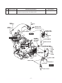
4-2 SPECIAL TOOLS
No Special Tool is needed for disassembling and reassembling the engine.
For pulling off the flywheel, universal type puller being popular in the market place as shown in
the illustration is needed.
Description
Parts number
Flywheel puller for pulling off the flywheel
228-95001-17
Flywheel puller with bolt
-4-
4-3 DISASSEMBLY PROCEDURES (DIFFERENCE)
Step
8
Parts to remove
Remarks and procedures
Parts Fasteners
Choke lever
Choke lever not applicable.
Governor rod
(1) Remove the governor rod spring from rod holder.
(2) P
ick up the rod holder and remove the governor rod.
(See Fig.4-1)
(3) R
emove the governor rod and the rod spring from
the governor lever.
9
(4) L
oosen the bolt and remove the governor lever.
M6 bolt and washer : 1pc.
STEP 9
THROTTLE BODY
R
GOVERNOR LEVER
L
GOVERNOR SHAFT
ROD HOLDER
A
GOVERNOR
ROD
ROD SPRING
ROD HOLDER
Turn the rod holder
clockwise to loosen.
VIEW A
GOVERNOR ROD
Fig. 4-1
-5-
Step
Parts to remove
Throttle body
Remarks and procedures
Parts Fasteners
(1) D
isconnect the two connectors from ECU under the
throttle body.
(2) D
isconnect the two connectors from the two injectors
on the throttle body.
10
(3) R
emove the nuts, adapter and throttle body from the
intake manifold.
STEP 10
CLEANER
ADAPTER
CONNECTER
(INJECTOR)
M6 Flange nut : 4pcs.
CONNECTER
(INJECTOR)
CONNECTER
(ECU)
GOVERNOR LEVER
-6-
M6 FLANGE NUT
Step
13
Parts to remove
Fuel pump
Remarks and procedures
Parts Fasteners
(1) Disconnect the connecter places from fuel pump wiring harness 2.
(2) R
emove fuel pump ASSY and detach bracket.
M6 x 12 Flange bolt : 1 pc.
#1
IGNITION
COIL
PLUG
TERMINAL
M6 BOLT AND
WASHER ASSY
SPARK
PLUG CAP
TO THROTTLE BODY
(ECU)
M6 BOLT AND
WASHER ASSY
STEP 14
#1 CYLINDER SIDE
#2
IGNITION
COIL
GROMMT
(PLUG CAP)
#2 CYLINDER
SIDE ONLY
PLUG TERMINAL
SPARK PLUG CAP
#2 CYLINDER SIDE
TO THROTTLE BODY
(ECU) and KEY SWITCH
HOSE
CLAMP
FUEL
PIPE
CONNECTER
(FUEL PUMP)
HOSE
CLAMP
HOSE CLAMP
HOSE CLAMP
M6 FLANGE BOLT
FUEL PUMP
STEP 13
FUEL FILTER
-7-
Step
Parts to remove
Regulator and Wire CP
16
21
Spark plug
Remarks and procedures
Parts Fasteners
(1) D
isconnect wire connector from regulator, and then
remove regulator from #1 cylinder baffle.
(2) R
emove temperature sensor from main bearing cover.
(3) D
isconnect the wiring harness 1.
(injector #1 / 2, temperature sensor, ignition coil #1 / 2)
(4) D
isconnect the wiring harness 2
(fuel pump, ground, warning lamp, ignition coil ground)
M6 x 12 Flange bolt : 2 pcs.
Take care the spark plug is hot just after stopping engine.
NGK : BPR5ES or BPR4EY
Tapping screw : 1pc.
STEP 16
M8 FLANGE NUT
WIRING HARNESS
STEP 15
GASKET
TO KEY
SWITCH
INTAKE MANIFOLD
WHITE
#1 CYLINDER SIDE
M8 FLANGE
NUT
M6 FLANGE
BOLT
REGULATOR
GASKET
#2 CYLINDER SIDE
CYLINDER
BAFFLE #1
TO THROTTLE BODY
(ECU)
TAPPING
SCREW
TEMPERATURE SENSOR
WIRING HARNESS 1
STEP 16
WIRING HARNESS 2
r
y(G
Gr
k(
Bl
k(
Bl
k
Bl
lk)
k(B
Bl
k)
Gr
l
y(B
)
IG COIL
GROUND
k(W
Bl
lk)
k
Bl
(B
lk)
BATTERY
k(B
Bl
R
)
TO THROTTLE
BODY "R"SIDE
WIRING COLOR CODE
Gry : Gray
lk)
(B
Blk(R
TO THROTTLE
BODY "L"SIDE
Blk : Black
WARNING
LAMP
lk)
TO IGNITION COIL #2
TO IGNITION COIL #1
POWER
GROUND
k(B
Bl
lk)
k/B
Bl
k(
Bl
FUEL PUMP
CONNECTER
(BLACK)
R)
INJECTOR #1 INJECTOR #2
TEMPERATURE
CONNECTER
)
)
SENSOR
n/R
(GRAY)
Gr
n/R
R : Red
(
Grn : Green
W : Wite
-8-
) is inside wiring color code.
4-4 REASSEMBLY PROCEDURES (DIFFERENCE)
20) COOLING FAN
Attach cooling fan onto flywheel.
M6 x 16 bolt & washer : 4 pcs.
0%2/7DQG
:$6+(5SFV
Tightening torque
6.8 - 8.8 N•m
(70 - 90 kgf•cm)
(5.1 - 6.5 ft•lb.)
&22/,1*)$1
21) THROTTLE BODY
(1) Replace the gasket of manifold with a new
one and mount the throttle body on the
intake manifold.
(2) Replace the gasket of throttle body with a
new one and mount the cleaner adapter on
the throttle body.
M6 FLANGE NUT : 4pcs.
INTAKE
MANIFOLD
THROTTLE
BODY
CLEANER
ADAPTER
GASKET
INJECTOR
Tightening torque
GASKET
6.8 - 8.8 N•m
(70 - 90 kgf•cm)
(5.1 - 6.5 ft•lb.)
WIRING
HARNESS #1
WIRING
HARNESS #2
(3) Connect the connectors from ECU to the injectors.
22) IGNITION COIL and WIRE CP
(1) Temporally fit ignition coil to crankcase.
Adjust air gap between ignition coil and flywheel using a thickness gauge and tighten bolts.
Ignition coil air gap
7+,&.1(66*$8*(
0.3 - 0.5 mm
(0.012 - 0.020 in.)
M6 x 30 bolt & washer : 4pcs.
,*1,7,21&2,/
:,5(
Tightening torque
6.8 - 8.8 N•m
(70 - 90 kgf•cm)
(5.1 - 6.5 ft•lb.)
(2) Connect wiring from ECU to the primary
terminal of ignition coil.
(3) Clamp the wiring harness with wire bands
to the intake manifold.
-9-
GOVERNOR
ROD
GOVERNOR
LEVER
Turn the rod holder
counter clockwise
and fix it.
A
Then hook the rod
spring as shown
on the diagram.
GOVERNOR ROD
THROTTLE LEVER
R
ROD
SPRING
GOVERNOR
SHAFT
L
23) GOVERNOR LEVER
Attach governor rod and rod spring
between governor lever and throttle body
throttle lever, and insert the governor lever
to governor lever shaft. Tighten locking bolt
temporarily.
ROD SPRING
ROD HOLDER
VIEW A
ROD HOLDER
24) SPEED CONTROL LEVER
(1) Install speed control bracket onto intake
manifold.
(2) Attach return spring, spacer, friction
washer, wing nut, etc. to speed control lever
as shown in the ilustration.
(3) Connect governor spring to governor lever
and speed control lever.
M6 SELF LOCK
NUT
STOP PLATE
SPRING WASHER
FRICTION
WASHER
SPEED CONTROL
LEVER
FRICTION
WASHER
M6 FLANGE
BOLT
,17$.(0$1,)2/'
7+5277/(%2'<
&/($1(5$'$37(5
BRACKET UNIT,
speed control
/
*29(5125
*($5
Fitting location of governor rod and governor spring
E
D
5
*29(5125
/(9(5
EH72 FI
52'635,1*
*29(5125
52'
)8//23(1
)8//&/26(
$
/2&.187
*29(5125635,1*
%
$'-867,1*
6&5(:
63(('&21752//(9(5
+,*+63(('
/2:63(('
- 10 -
50 Hz
60 Hz
NA
A-2(a)
25) ADJUST GOVERNOR SYSTEM
●●Governor system is centrifugal flyweight
type. Governor weight is installed into
governor gear driven by crankshaft.
Governor weight movement is transferred
to throttle lever via governor shaft and
lever.
GOVERNOR LEVER
●●Engine
speed is maintained at the constant
speed by throttle valve opening and closing
operation in accordance with load condition
of engine.
GOVERNOR SHAFT
(1) Push speed control lever all the way to the
high speed position and fix it by tightening
nut.
(2) Check that governor lever is pulled by
governor spring and throttle valve is fully
open.
(3) Turn governor shaft counterclockwise all
the way and tighten lock bolt to secure the
lever on the shaft.
26) BLOWER HOUSING
Attach blower housing to crankcase with
control box commonly fixed.
Connect fuel pipes onto blower housing.
BLOWER HOUSING(Front)
M6 x 14 Flange bolt : 4 pcs.
Tightening torque
BLOWER
HOUSING
(Side)
BLOWER
HOUSING
(Front)
3.9 - 5.9 N•m
(40 - 60 kgf•cm)
(2.9 - 4.3 ft•lb.)
Connect the wiring to
the electric starter.
BLOWER HOUSING(Side)
M6 x 18 Flange bolt : 2 pcs.
M6 x 14 Flange bolt : 2 pcs.
Tightening torque
2.9 - 4.9 N•m
(30 - 50 kgf•cm)
(2.2 - 3.6 ft•lb.)
- 11 -
27) FUEL PUMP and FUEL PIPE
(1) Install fuel pump bracket onto #2 cylinder
baffle.
FUEL PUMP
M6 x 12 Flange bolt : 1 pc.
RETURN HOSE
FUEL PUMP
Tightening torque
6.8 - 8.8 N•m
(70 - 90 kgf•cm)
(5.0 - 6.5 ft•lb.)
FUEL FILTER
PULSATION DAMPER
(2) Connect the wiring to the fuel pump.
(3) Connect fuel pipe between throttle body
and fuel pump.
28) AIR CLEANER and BREATHER PIPE
(1) Connect breather pipe to air cleaner base.
(2) Fit air cleaner base onto throttle body.
M6 x 12 Flange bolt : 3 pcs.
AIR CLEANER BASE
Tightening torque
6.8 - 8.8 N•m
(70 - 90 kgf•cm)
(5.0 - 6.5 ft•lb.)
(3) Connect breather pipe to #1 cylinder head.
(4) Set air cleaner element along with urethane
foam onto base.
(5) Install air cleaner cover with knob.
29) OIL PRESSURE SWITCH
(1) Install oil pressure switch onto adapter (Oil
cooler).
Tightening torque
5.9 - 9.8 N•m
(60 - 100 kgf•cm)
(4.3 - 7.2 ft•lb.)
NOTE ;
Not to tighten excessively.
2,/35(6685(6:,7&+
(2) Connect the wiring to the oil pressure
switch.
- 12 -
CONNECTER
(FUEL PUMP)
30) OIL FILTER
Apply oil to O-ring and install oil filter by
tightening about 3/4 turns after attaching
crankcase surface.
Tightening torque
9.9 - 14.7 N•m
(100 - 150 kgf•cm)
(16.3 - 19.8 ft•lb.)
3/4 TURNS
OIL FILTER
NOTE ;
Start engine after assembling,
and check for no oil leakage
from oil filter.
O RING
31) MUFFLER
(1) Install Muffler bracket onto Cylinder head.
M8 x 20 bolt & washer : 2 pcs.
M6 FLANGE BOLT
Tightening torque
MUFFLER
COVER
16.6 - 18.6 N•m
(170 - 190 kgf•cm)
(12.3 - 13.7 ft•lb.)
(2) Install Muffler onto Muffler bracket and
Cylinder head.
M8 SUS flange nut : 4 pcs.
M6 FLANGE
M6 FLANGE BOLT
BOLT
Tightening torque
A
16.6 - 18.6 N•m
(170 - 190 kgf•cm)
(12.3 - 13.7 ft•lb.)
MUFFLER
MUFFLER
BLACKET
(3) Install Muffler cover onto Muffler.
M6 Flange bolt : 6 pcs.
A
M8 BOLT & WASHER
Tightening torque
6.8 - 8.8 N•m
(70 - 90 kgf•cm)
(5.0 - 6.5 ft•lb.)
- 13 -
GASKET
M8 SUS
FLANGE NUT
32) FINAL CHECK
Be sure to check loosen bolts and nuts, and also electric wiring connections.
33) ENGINE OIL
Refill engine oil and start the engine.
Engine oil will be lubricated oil passages
and oil filter. Check the engine oil level and
refill again to the upper level of oil level
gauge.
Standard
Option
2,/*$8*(
Oil Capacity
1.55 liter (0.41 U.S. gal.)
NOTE ;
* Check the oil level with the oil gauge inserted.
* Use “SE” (API classification) or higher grade
engine oil.
2,/*$8*(
833(5/(9(/
OIL GAUGE
OIL GAUGE
UPPER LEVEL
UPPER LEVEL
LOWER LEVEL
LOWER LEVEL
/2:(5/(9(/
4-5 BREAK-IN OPERATION
An engine that has been completely overhauled by being fitted with a new piston, rings, valves
and connecting rod should be thoroughly RUN-IN before being put back into service. Good
bearing surfaces and running clearances between the various parts can only be established by
operating the engine under reduced speed and loads for a short period of time.
While the engine is being tested, check for oil leaks.
Make final carburetor adjustment and regulate the engine operating speed.
STEP
EH72 FI
1
2
No Load
3
Engine speed (rpm)
Time (minute)
2500
10
3000
10
3600
10
4
7.5kW (10.0HP)
3600
30
5
14.9kW (20.0HP)
3600
30
- 14 -
5. DIAGRAM
WIRING
W
Blk
Blk
R
THROTTLE
BODY
#2 CYLINDER SIDE
CLEANER
ADAPTER
(Wiring harness 2)
IGNITION
COIL #2
#2
CYLINDER
SIDE
#1
CYLINDER
SIDE
Blk Blk
R
R
Blk / W
R
Y
W
TACHO /
HOUR METER
(OPTION)
Blk
Blk (Covering: Gry)
IGNITION
SPARK COIL #1
PLUG
TEMPERATURE
SENSOR (MBC)
SPARK
PLUG
G M B L S
KEY SWITCH
(OPTION)
BATTERY
12V
12V-36AH
or larger
ELECTRIC
STARTER
Grn
OFF
RUN
START
REGULATOR
BODY
REGURATOR
CHARGE
COIL
Y
Y
Blk
Blk
(Covering: Blk)
Gry
Blk Grn
(Wiring harness 1)
Grn, R
(Covering: Gry)
W
OIL
PRESSURE
SWITCH
R
R
R
L
#1 CYLINDER SIDE
Blk
Gry
Blk
Blk
OIL/FAIL WARNING LAMP
(OPTION)
ELECTRIC
FUEL PUMP
Blk
Grn, R
(Covering: Blk)
Blk : BLACK
W : WHITE
R : RED
Y : YELLOW
Grn : GREEN
Gry : GRAY
SYSTEM BLOCK
DELIVERY
RETURN
FUEL TANK
ELECTRIC
FUEL
FUEL FILTER
AIR PRESSURE
FUEL PUMP
THROTTLE BODY
PULSATION
DAMPER
INJECTOR #1
KEY SW
FUEL
REGULATOR
ECU
INJECTOR #2
BATTELY
MAP SENSOR
MBC TEMPERATURE SENSOR
IG COIL #1 R.P.M
ECU
: Engine Control Unit
MAP SENSOR : Manifold Air Pressure Sensor
IG COIL #2 R.P.M
- 15 -
INTAKE BOOST
#1 CYL SIDE
6. THROTTLE BODY
6-1 SPECIFICATIONS
This engine is equipped with Electronic Fuel Injection system (FI system) integrated with ECU
(Engine Control Unit).
The FI system consists of throttle body (2-barrel), ECU, MAP (Manifold Air Pressure) sensor,
injector, pressure regulator, temperature sensor, electric fuel pump, and pulsation damper.
The fuel system is calibrated after careful testing for optimum all-round performance (including
starting, acceleration, fuel consumption, output power characteristics).
The throttle body monitors air and engine temperature at start up and performs the choke
function automatically.
While the engine is in operation, the throttle body monitors engine speed, manifold air pressure,
and engine temperature to ensure proper engine performance.
6-2 FUNCTIONS AND CONSTRUCTION
6-2-1 ELECTRIC FUEL PUMP
The electric fuel pump is located below the throttle body, and actuated by power from the DC
battery. The fuel flows from the tank into the fuel pump. When the fuel pump is actuated by DC
battery, the fuel is pressurized by the pump and pushed into the throttle body pressure port.
6-2-2 FUEL PRESSURE REGULTOR
After the fuel pressure port is a diaphragm-type fuel pressure regulator.
The fuel pressure regulator relieves the throttle body of any excess fuel pressure and returns
excess fuel pressure back to the fuel tank through the fuel pressure return pipe.
6-2-3 FUEL INJECTOR
The throttle body pressure port feeds fuel at a regulated pressure to the fuel injectors.
Fuel is metered by the fuel injector that is actuated electronically by ECU.
The fuel is injected into the throttle bore and mixed with air from the air cleaner.
6-2-3 ENGINE CONTROL UNIT (ECU)
The ECU (engine control unit) on bottom of the throttle body is powered by DC battery. The
ECU monitors engine conditions such as engine speed, air pressure, and engine temperature.
With these inputs, the ECU actuates the fuel injector to ensure the fuel/air mixture is of optimum
concentration and is fed into the combustion chamber of the engine at the correct timing. When
engine speed reached to 4,200 rpm, the ECU cuts fuel to prevent over speed.
The ECU also controls the low oil sensor system and monitors voltage of DC battery, and each
wiring whether disconnecting or electrical short circuit.
- 16 -
6-2-4 WIRE HARNESS
The wire harness for the FI system connects key system components to the ECU.
The FI wire harness contains a temperature sensor that measures engine temperature, and
connects fuel injectors, ignition coils, electric fuel pump, pressure switch, and warning lamp.
The ECU uses this input to adjust to engine various conditions and monitors for failure diagnosis.
6-2-5 CHOKE SYSTEM
The throttle body monitors air pressure and engine temperature at start up and performs the
choke function automatically.
The choke system automatically adjusts for easier start of the engine in all weather conditions.
6-3 FUEL SYSTEM OUTLINE
Throttle Body Assy
Fuel Injector
Fuel Pressure Regulator
M.A.P. Sensor
Air
Cleaner
Return
Muffler
ECU
Magneto
Ignition
Unit
Engine
Temperature
sensor
Ignition Pulse
TANK
FILTER
PIPE
FUEL
PUMP
30kPa
(0.3kgf/cm2)
PULSATION
DAMPER
PULSATION
DAMPER
Fuel
Filter
Fuel
Pump
FUEL
INJECTION
Fuel Tank
COMBUSION
FUEL RETURN PIPE
6-4 FUEL SYSTEM TESTING AND DIAGNOSIS
Most fuel system malfunctions occur when the fuel/air ratio of the mixture is not correct.
This is usually caused by clogged fuel filters, air passages, fuel passages, or by variations in
the fuel level.
To get the best possible performance from the throttle body, make sure that the fuel feed and
air feed passages are free so air and fuel can flow freely through them.
The procedure for inspecting the fuel system is described below.
Run all system tests with a full tank of fresh, clean fuel.
- 17 -
7. INSTALLATION
Engine life, ease of maintenance and inspection, frequency of checks and repairs, and operating
cost all depend on the way in which the engine is installed. Review the following instructions
carefully for installing the engine.
7-1 INSTALLING
When mounting the engine, carefully examine its position, the method of connecting it to a
machine, the foundation, and the method of supporting the engine.
When determining its mounting position, in particular, make sure that gasoline and oil can
easily be supplied and checked, the spark plug can easily be checked, the air cleaner can
easily be serviced, and that the oil can easily be discharged.
7-2 VENTILATION
Fresh air is necessary for cooling the engine and burning the fuel.
In the case the engine is operated under a hood or in a small room, temperature rise in the
engine room can cause vapor lock, oil deterioration, increased oil consumption, loss of power,
piston seizure, shorter engine life, etc., making it impossible to operate the engine properly. It
is necessary, therefore, to provide a duct or baffle to guide cooling air to the engine to prevent
recirculation of he hot air used for engine cooling, and temperature rise of the machine.
Keep the engine room temperature below 50°C even in the hottest period of the year.
7-3 EXHAUST GAS DISCHARGE
Exhaust gas is noxious. When operating the engine indoors, be sure to discharge the exhaust
gas outdoors. If a long exhaust pipe is used in such a case, the internal resistance increases
causing loss of engine power. Thus pipe inside diameter must be increased in proportion to
exhaust pipe length.
Exhaust pipe : Less than 3 m long --- pipe inside diameter 30 mm.
Less than 5 m long --- pipe inside diameter 33 mm.
- 18 -
7-4 FUEL SYSTEM
When the fuel tank is mounted remote position from the engine, the height from the bottom of
the fuel tank to the fuel joint of the throttle body should be 500 mm and less.
The bottom of the fuel tank can be up to 400 mm below the throttle body.
Position the fuel tank carefully because, when it is low, fuel is not fed to the throttle body,
and when it is high, it can cause high pressure in the throttle body then fuel rich and high fuel
consumption.
When piping the fuel, the hose should be as short as possible and attention should be paid to
heat transmission, size, bending, and leakage at hose joints and so on.
Care should also be taken to prevent air lock and vapor lock. It is required that return piping to
the fuel tank from the fuel pressure regulator on throttle body.
7-5 POWER TRANSMISSION TO DRIVEN MACHINES
7-5-1 BELT DRIVE
Take the following notes into consideration.
* V-belts are preferable to flat belts.
* The driving shaft of the engine must be parallel to the driven shaft of the machine.
* The driving pulley of the engine must be in line with the driven pulley of the machine.
* Install the engine pulley as close to the engine as possible.
* If possible, span the belt horizontally.
* Disengage the load when starting the engine.
If no clutch is used, use a belt tension pulley or the like.
7-5-2 FLEXIBLE COUPLING
When using a flexible coupling, run out and misalignment between the driven shaft and engine
shaft must be minimized. Run out and misalignment tolerance are specified by the coupling
manufacturer.
- 19 -
8. TROUBLESHOOTING
The following three conditions must be fulfilled for satisfactory engine start.
(1) The cylinder filled with a proper fuel-air mixture.
(2) Good compression in the cylinder.
(3) Good spark, properly timed, to ignite the mixture.
The engine cannot be started unless these three conditions are met.
There are also other factors which make engine start difficult, e.g., a heavy load on the engine
when it is about to start at low speed, and a high back pressure due to a long exhaust pipe.
The most common causes of engine troubles are given below:
8-1 NO ENGINE OPERATION
Phenomenon
Possible causes
1) Poor connection of key switch wiring
Remedy
Check, repair or replace
2) Wiring discontinuity between key switch and starter motor Replace
1. Electric starter
does not
operate.
2. Electric starter
operates, but
engine does
not start.
3) Wiring discontinuity between battery and starter motor
Replace
4) Improper battery (low capacity) or discharged battery
Charge or replace battery
5) Poor connection of battery terminal
Check, clean or replace
6) Starter magnetic switch faulty
Check, clean, repair or replace
7) Starter motor faulty
Repair or replace
8) Crankshaft seizure
Check, repair or replace
9) Seizure between piston and cylinder
Check, repair or replace
1) No fuel
Refill
2) Poor connection or discontinuity of ignition system wirings Check, repair or replace
3) Electric starter faulty
Repair or replace
- 20 -
8-2 STARTING DIFFICULTIES
Phenomenon
1. Low engine
speed at
starting
2. Ignition
system
malfunction
3. Fuel system
malfunction
4. Engine core
components
malfunction
Possible causes
Remedy
1) Battery discharged
Charge battery
2) Poor connection between battery and starter motor
Clean or repair
3) Poor connection between battery and ground
Clean or repair
4) Electric starter faulty
Repair or replace
5) Improper engine oil
Replace with recommended
engine oil
Spark plug
* Improper spark plug gap
* No insulation
* Carbon deposits
Adjust
Replace
Clean
Ignition coil
* No insulation or discontinuity
* Poor connection or discontinuity of ignition code
Check with failure diagnosis system
Replace
Repair or replace
Improper air gap between ignition coil and flywheel
Adjust
1) No fuel in fuel tank
Refill
2) Fuel pump clogged
Clean or replace
3) Fuel hose clogged or pinched
Clean or replace
4) Air mixing into fuel lines
Check and adjust connecting portion
5) Improper gasoline or water infiltration
Replace
6) Throttle body
* Poor connection or discontinuity of throttle body (ECU).
* Clogged or damaged
* Improper operation of throttle valve
Repair or replace.
Check with failure diagnosis system
Clean or replace
Check and adjust or replace
7) Poor connection of fuel pump wiring
Check with failure diagnosis system
8) Improper pulsation damper
Replace
9) Improper temperature sensor
Check with failure diagnosis system
and replace
1) Insufficient tightening of cylinder head bolts
Check and retighten
2) Wear of piston, piston ring and/or cylinder
Repair or replace
3) Improper contact of valve and seat
Repair
4) Valve seizure
Repair
5) Improper valve clearance
Adjust
6) Intake manifold gasket leakage
Retighten intake manifold bolts or
replace gasket
7) Throttle body gasket leakage
Retighten cleaner adapter flange
nut or replace gasket
8) Insufficient tightening of spark plug
Retighten
- 21 -
8-3 INSUFFICIENT OUTPUT
Phenomenon
1. Low
compression
2. Ignition system
malfunction
3. Fuel system
malfunction
4. Low intake air
volume
Possible causes
Remedy
1) Loosen spark plug
Retighten or replace gasket
2) Cylinder head gasket leakage
Retighten or replace gasket
3) Piston ring(s) seizure or wear
Replace
4) Piston or cylinder wear
Repair or replace
5) Incorrect valve and seat contact
Repair or replace
6) Valve stem seizure
Repair or replace
7) Improper valve clearance
Adjust
1) Spark plug faulty
Replace
2) Ignition coil faulty
Replace
3) Improper air gap between ignition coil and flywheel
Adjust
4) Magneto demagnetization
Replace
1) Throttle body clogged
Check and replace
2) Improper fuel pump operation
Check and replace
3) Fuel strainer or fuel hose clogged
Clean or replace
4) Air mixing into fuel lines
Check and adjust connecting portion
5) Improper gasoline or water infiltration
Replace
6) Improper pulsation damper operation
Replace
1) Air cleaner clogged
Clean or replace
2) Throttle valve faulty
Repair or replace
8-4 OVERHEAT
Phenomenon
Overheating
Possible causes
Remedy
1) Cooling air flow obstructed at inlet or cylinder baffle portion
Clean
2) Improper engine oil
Replace
3) Lean air/fuel mixture
Check and replace throttle body,
and pulsation damper
4) Excessive back pressure of exhaust system
Check, clean or replace
5) Over-load
Change to rated load
6) Clogged oil cooler
Check and clean or replace
7) Loosen or missing spark plug cap
Check and connect properly
- 22 -
8-5 ROUGH IDLING
Phenomenon
Possible causes
Remedy
1) Low idling speed
Adjust
2) Throttle body slow system passage clogged
Check, clean and replace
2. Intake system
1) Air mixing from connecting portion of air intake system
Check, tighten or replace gasket
3. Cylinder head
1) Cylinder head gasket faulty (blow-by)
Replace
1) Improper valve clearance
Adjust
2) Leakage from valve seat
Adjust valve seat contact
3) Excessive clearance between valve stem and guide
Replace
1. Throttle body
4. Valve system
5. Ignition system 1) Weak ignition spark
Check and replace spark plug
8-6 HIGH ENGINE OIL CONSUMPTION
Phenomenon
1. Oil leakage
2. Oil dilution
Possible causes
Remedy
1) Loosen drain plug
Tighten
2) Drain plug gasket damaged
Replace
3) Incorrect oil filter fitting
Repair
4) Loosen main bearing cover bolts
Tighten
5) Main bearing cover gasket damaged
Replace
6) Crankshaft oil seal damaged
Replace
1) Piston oil ring faulty
Replace
2) Piston rings seizure, wear or poor contact
Replace
3) Excessive wear of piston and cylinder
Replace
4) Excessive wear of valve stem
Replace
5) High oil level
Adjust oil level
6) Breather faulty
Repair or replace
- 23 -
8-7 HIGH FUEL CONSUMPTION
Phenomenon
1. Fuel system
2. Engine core
components
Possible causes
Remedy
1) Throttle body faulty
Check or replace
2) Pulsation damper faulty
Check or replace
3) Fuel pump faulty
Check or replace
1) Low compression
Check or repair
2) Over cooling
Check and adjust load and/or
engine speed
8-8 DETONATION
Phenomenon
1. Ignition system
malfunction
2. Fuel system
malfunction
3. Cylinder head
4. Valve system
Possible causes
Remedy
1) Poor connection of ignition system wirings
Check with failure diagnosis
system and connect properly
2) Improper or damaged spark plug
Clean or replace
1) Lean or rich air/fuel mixture
Check or replace throttle body
2) Throttle body damaged
Check or replace throttle body
3) Fuel lines clogged or damaged
Clean or replace
4) Air mixing from connecting portion of air intake system
Connect properly or replace
gasket
1) Carbon deposit in combustion chamber
Remove and clean
2) Cylinder head gasket faulty (blow-by)
Replace
1) Improper valve clearance
Adjust
2) Valve heat deterioration
Replace
3) Valve spring deterioration
Replace
4) Improper valve timing
Adjust
- 24 -
8-9 ENGINE MISFIRE
Phenomenon
1. Ignition system
2. Fuel system
3. Engine core
componets
Possible causes
Remedy
1) Improper spark plug gap or damaged electrode
Cealn, adjust or replace
2) Ignition coil faulty
Replace
3) Damaged ignition system wirings
Check with failure diagnosis
system and replace
4) Poor connection of ignition system wirings
Check with failure diagnosis
system and connect properly
1) Lean or rich air/fuel mixture
Check and replace throttle body
2) Clogged throttle body
Check and replace
3) Throttle body faulty
Check and replace
4) Pulsation damper faulty
Check and replace
5) Fuel pump faulty
Check and replace
6) Improper gasoline or water infiltration
Replace
1) Valve heat deterioration or improper valve adjustment
Adjust or replace
2) Valve spring deterioration
Replace
3) Low compression
Check, adjust or replace
- 25 -
8-10 DIAGNOSIS CODE
This engine has the failure diagnosis system to know that low voltage of DC battery and each
wiring whether disconnecting or electrical short circuit. The ECU monitors engine various
conditions for the system when tune the key to the “RUN” (ON) position, “START” (cranking) or
after start the engine. However, this is required the warning lamp or a lamp for DC12V to indicate
of the failure code. The warning lamp and so on is prepared as optional.
8-10-1 HOW TO OPERATION
When troubleshooting with the failure diagnosis, disconnect the grey wire to oil pressure switch.
If the wire will be not disconnected, the lamp will be lightning cause of the engine stopped and
no oil pressure.
If there is failure the components wiring, the warning lamp repeats turning on and off.
Finally, re-connect the grey wire to the oil pressure switch, after troubleshooting with failure
diagnosis system.
8-10-2 INDICATION MEANS and PROCEDURE
Step
Key position
Tune the key switch to
the “RUN” position.
Description
(a) L
ightning 2 sec and go out forever.
Not see any problem.
OFF
Lamp
RUN
1
(b) L
ightning 2 sec and go out 4 sec, then lightning again.
There is some problem.
START
Refer to step 2
Lamp
(a) After the 4 sec the lamp repeats turning on and off.
Go out 4 sec
OFF
RUN
2
This sample, failure code is “2-1”. Two (2) turning on and
off, and go out 2 sec then turning on 0.4 sec. After this go
out 4 sec and repeat the code again.
START
(b) If there is another failure, the lamp indicates continuity
with new code. Refer to step 3.
- 26 -
Step
Key position
Description
In case of another failure, after the 4 sec the lamp repeats
turning on and off.
This sample is failure code means “4-2”.
OFF
RUN
3
START
Fore (4) turning on and off, and go out 2 sec then turning
on 0.4 sec. After this go out 4 sec and repeat the code
again. If there is another failure, the lamp indicates
continuity with new code.
8-10-3 FAILURE CODE
Please refer to the following table for the failure diagnosis code.
Key position
Failure code
2-1
2-2
OFF
RUN
START
2-3
Low voltage of battery
Charging system failure
Disconnecting or short circuit internal of throttle body between
MAP sensor and ECU
Disconnecting or short circuit
between temperature sensor and ECU
3-1
Disconnecting between fuel pump and ECU
4-1
Disconnecting between fuel injector #1 and ECU
4-2
Disconnecting between fuel injector #2 and ECU
5-1
Disconnecting between ignition coil #1 and ECU
5-2
Disconnecting between ignition coil #2 and ECU
OFF
RUN
Possible causes
START
OFF
RUN
After starting the engine, the above codes also will be indicated.
START
- 27 -
9. MAINTENANCE AND STORAGE
9-1 DAILY MAINTENANCE
Every day before operating engine, check the following items :
MAINTENANCE ITEMS
REMARKS
1) Clean away dust and chaff from engine.
Governor linkage is especially sensetive to dust.
2) C
heck fuel leakage from fuel system. If any, retighten fasteners or replace necessary parts.
3) Inspect for loose hardware and retighten if
necessary.
Loose bolts and nuts may come off and result in
breakage of other parts.
4) Check oil level and add to full level.
9-2 PERIODIC MAINTENANCE SCHEDULE
Periodic maintenance is vital to safe and efficient operation of engine.
Check the table below for periodic maintenance intervals.
It is also necessary to conduct the maintenance and adjustments on the emission-related parts
listed below to keep the emission control system effective;
(1) Throttle body and
internal parts
(2) Cold start enrichment
system, if applicable
(3) Intake manifold, if
applicable
(4) Air cleaner elements
(5) Spark plug
(6) Magneto or electronic
ignition system
(7) Spark advance/retard
system, if applicable
(8) Exhaust manifold, if
applicable
(9) Hoses, belts, connectors,
and assemblies
The following maintenance schedule is based on the normal engine operation.
Should the engine be operated in extremely dusty condition or in heavier loading condition, the
maintenance interval must be shortened depending on the contamination of oil, clogging of filter
elements, wear of parts, and so on.
- 28 -
Periodic Maintenance Schedule table
Maintenance Items
Every
8 hours
(Daily)
Every
50 hours
(Weekly)
Clean engine and check bolts and nuts
● (Daily)
Check and refill engine oil
● (Refill daily up to upper level)
Change engine oil (*Note : 1)
● (Initial 20 hours)
Replace engine oil filter (*Note 1)
● (Initial 20 hours)
Every
200 hours
(Monthly)
Every
500
hours
Every
1000
hours
● (Every 100 hours)
●
Check battery electrolyte fluid level
●
Clean spark plug
●
Clean air cleaner
●
Clean spark arrester (Optional part)
● (Every 100 hours)
Replace air cleaner element
●
Clean fuel strainer
●
Clean and adjust spark plug and electrodes
●
Replace spark plug
●
Remove carbon from cylinder head
●
Clean throttle body
●
Clean engine base (oil pan)
●
Check and adjust valve clearance
●
●
Replace fuel lines
(Yearly)
●
Overhaul engine (*Note : 2)
*Note : 1. Initial oil change and oil filter replacement should be performed after 20 hours of operation.
Thereafter change oil every hundred (100) hours and replace oil filter 200 hours.
Before changing oil, check for a suitable way to dispose of old oil.
Do not pour it down into sewage drains, onto garden soil or into open streams.
Your local zoning or environmental regulations will give you more detailed instructions
on proper disposal.
*Note : 2. As to the procedures, please refer to the Service Manual or consult your nearest service dealer.
*Note : 3. More frequent oil changing, oil filter replacement and air cleaner service on replacement
may be necessary depending on operating conditions.
This would include dusty environment, high ambient temperature, heavy engine loading.
- 29 -
9-3 SPARK ARRESTER (OPTIONAL)
In a dry or wooded area, it is recommendable to use the product with a spark arrester. Some
areas require the use of a spark arrester. Please check your local laws and regulations before
operating your product.
The spark arrester must be cleaned regularly to keep it functioning as designed.
A clogged spark arrester :
●●Prevents the flow of exhaust gas
●●Reduces
engine output
●●Increases
●●Makes
fuel consumption
starting difficult
If the engine has been running, the muffler and the spark arrester will be very hot. Allow the
muffler to cool before cleaning the spark arrester.
08))/(5
63$5.
$55(67(5
6&5((1
How to remove the spark arrester
1. R
emove the flange bolts from the muffler
cover and remove the muffler cover.
2. R
emove the special screw from the spark
arrester and remove the spark arrester from
the muffler.
08))/(5&29(5
63$5.$55(67(56&5((1
Clean the spark arrester screen
Use a brush to remove carbon deposits from
the spark arrester screen.
Be careful to avoid damaging the screen.
The spark arrester must be free of breaks
and holes. Replace the spark arrester if it is
damaged.
Install the spark arrester, and muffler protector
in the reverse order of disassembly.
- 30 -
9-4 ENGINE STORAGE
(1) Drain fuel from fuel tank and run the engine until there is no fuel left.
(2) Change the engine oil and perform the daily maintenance items above mentioned.
(3) To prevent rust in the cylinder bore, apply oil through the spark plug hole and turn the
crankshaft several turns by hand. Reinstall the plug.
(4) Turn the crankshaft by hand and leave it where the resistance is the heaviest.
(5) Clean outside of the engine with oiled cloth.
(6) Put a plastic cover or the like over the engine and store the engine in dry place.
- 31 -
ISSUE EMD-ES6790
2009.08