1
EH72-2D
SERVICE INFORMATION
PREFACE
This manual covers the service information, trouble shooting procedures and so on of .
EH72-2 engine.
Careful observance of the instructions given herein will result in better, safer and faster
service work.
For more detailed instructions of disassembling and reassembling procedures, please .
refer to the service manual for EH63, 64, 65 and 72.
CONTENTS
Section
Title
Page
1. SPECIFICATIONS. . . . . . . . . . . . . . . . . . . . . . . . . . . . . . . . . . . . . . . . . . . . . . . . . . . . . . . . . . . . . 1
2. FEATURES . . . . . . . . . . . . . . . . . . . . . . . . . . . . . . . . . . . . . . . . . . . . . . . . . . . . . . . . . . . . . . . . . 2
3. DISASSEMBLY AND REASSEMBLY. . . . . . . . . . . . . . . . . . . . . . . . . . . . . . . . . . . . . . . . . . . . . . . 3
3-1 PREPARATIONS AND SUGGESTIONS. . . . . . . . . . . . . . . . . . . . . . . . . . . . . . . . . . . . . . . . . . . . . . . 3
3-2 SPECIAL TOOLS. . . . . . . . . . . . . . . . . . . . . . . . . . . . . . . . . . . . . . . . . . . . . . . . . . . . . . . . . . . . . . . . . 3
3-3 DISASSEMBLY PROCEDURES (DIFFERENCE). . . . . . . . . . . . . . . . . . . . . . . . . . . . . . . . . . . . . . . . 4
3-4 REASSEMBLY PROCEDURES (DIFFERENCE). . . . . . . . . . . . . . . . . . . . . . . . . . . . . . . . . . . . . . . . 6
3-5 BREAK-IN OPERATION. . . . . . . . . . . . . . . . . . . . . . . . . . . . . . . . . . . . . . . . . . . . . . . . . . . . . . . . . . . 8
4-1 CARBURETOR. . . . . . . . . . . . . . . . . . . . . . . . . . . . . . . . . . . . . . . . . . . . . . . . . . . . . . . . . . . . . . . . . . 9
4-2 COMPORNENT PARTS . . . . . . . . . . . . . . . . . . . . . . . . . . . . . . . . . . . . . . . . . . . . . . . . . . . . . . . . . . 11
1. SPECIFICATIONS
Model
EH72-2D
Air-Cooled, 4-Stroke, V-Twin Cylinder, Horizontal P.T.O. shaft, .
OHV Gasoline Engine
Type
Number of Cylinders - Bore×Stroke
mm (in.)
Displacement
ml (cu.in.)
2 - 84 × 65 (3.31 × 2.56)
720 (43.9)
Compression Ratio
8.7
Continuous Output
kW(HP)/r.p.m.
14.2 (19.0) / 3600
Maximum Output
kW(HP)/r.p.m.
Gross : 18.7 (25.0) / 3600
Maximum Torque
N•m / r.p.m.
(kgf•m / r.p.m.)
(ft•lb. / r.p.m.)
51.0 / 2800
(5.2 / 2800)
(37.6 / 2800)
Direction of Rotation
Counterclockwise as viewed from the P.T.O. shaft side
Cooling System
Forced air cooling
Valve Arrangement
Overhead Valve (OHV)
Lubrication
Full pressure type with oil Cooler
Automobile engine oil SAE #20, #30 or 10W-30; .
Class SE or higher
Lubricant
Capacity of Lubricant
L (U.S. gal.)
1.55 (0.41)
Carburetor
2- Barrel side draft type
Fuel
Automotive unleaded gasoline
Fuel Feed System
Diaphragm Fuel pump (Pulse type)
Ignition System
Flywheel Magneto (Solid state)
Spark Plug
BPR5ES(NGK) or BPR4EY(NGK)
Charging Capacity
V-A
12 - 15 or 12 - 30 (Option)
Starting System
Electric Starter
Governor System
Centrifugal Flyweight type
Air cleaner
Dry Weight
Double Element type
kg (lb.)
Dimensions
(L×W×H) mm (in.)
with out muffler and control box
46 (101.3)
with STD muffler and control box
51.5 (113.4)
with out muffler and control box
317×477×480 (12.5×18.8×18.9)
with STD muffler and control box
464×499×480 (18.3×19.6×18.9)
* Specifications are subject to change without notice.
-1-
2. FEATURES
HIGH OUTPUT, TORQUE AND DURABILITY
720cc displacement which is the largest among 25 horsepower classed engines, produces high
torque from the low speed range. High durability with less than 1% horsepower drop after 300
hours of full-throttle operation.
Furthermore, the new generation of EH72 (EH72-2) has achieved higher output by adopting .
2- Barrel Side draft carburetor system, which increases intake airflow and optimally distributes .
air-fuel to each cylinder, as well as optimizing camshaft profile and increasing compression ratio.
INTAKE MANIFOLD
HEAVY DUTY CONSTRUCTON
Reliable structure with pressure lubrication, cast iron cylinder sleeve and dual air cleaner element. Also, heavy duty ball bearing installed on P.T.O. side.
SUPERIOR OIL CONTROL
In addition to the excellent oil control by 3 pieces oil rings, adoption of valve stem seal and high
cooling capability reduce oil consumption. This enables longer oil maintenance interval together
with largest lubrication oil capacity in this class.
-2-
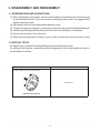
3. DISASSEMBLY AND REASSEMBLY
3-1 P
REPARATIONS AND SUGGESTIONS
(1) When disassembling the engine, memorize the locations of individual parts so that they can
be reassembled correctly. If you are uncertain of identifying some parts, it is suggested that
tags be attached to them.
(2) Have boxes ready to keep disassembled parts by group.
(3) To prevent losing and misplacing, temporarily assemble each group of disassembled parts.
(4) Carefully handle disassembled parts, and clean them with washing oil if necessary.
(5) Use the correct tools in the correct way.
(6) When disconnecting electric wirings, be sure to hold and disconnect the connector housing.
3-2 S
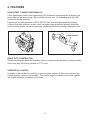
PECIAL TOOLS
No Special Tool is needed for disassembling and reassembling the engine.
For pulling off the flywheel, universal type puller being popular in the market place as shown in
the illustration is needed. Description
Parts number
Flywheel puller for pulling off the flywheel
228-95001-17
Flywheel puller with bolt
-3-
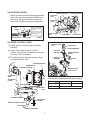
3-3 DISASSEMBLY PROCEDURES (DIFFERENCE)
Step
8
Parts to remove
Chock control
lever and link
Remarks and procedures
Parts Fasteners
(1) D
isconnect the choke rod holder and remove
the choke control rod. (See Fig. 3-1)
(2) Remove the choke knob.
CONTROL BOX
LINK PIVOT
CHOKE
CONTROL ROD
RETURN
SPRING
STEP 8
BLOWER HOUSING
M5 TAPPING
SCREW
CLAMP
CHOKE
KNOB
CHOKE
CONTROL
LINK
M6 FLANGE
BOLT
M6 FLANGE BOLT
Fig. 3-1
-4-
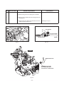
Step
Parts to remove
Carburetor
9
Remarks and procedures
Parts Fasteners
(1) At first remove fuel pipe. (See Fig.3-2).
.
(2) Remove the governor rod spring from rod holder..
.
(3) Pick up the rod holder and remove the governor rod.
(See Fig.3-3)
.
(4) Remove the nuts, adapter and Carburetor from the
intake manifold. (See Fig.3-4)
M6 Flange nut : 4pcs.
ROD HOLDER
Turn the rod holder
clockwise to loosen.
VIEW A
GOVERNOR ROD
FUEL PIPE
Fig. 3-2
Fig. 3-3
STEP 9
#1 CYLINDER SIDE
A
SPARK PLUG CAP
#2 CYLINDER SIDE
GROMMT (PLUG CAP)
#2 CYLINDER SIDE ONLY
AS OPTION #1 CYLINDER SIDE
Fig. 3-4
-5-
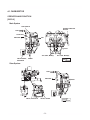
3-4 REASSEMBLY PROCEDURES (DIFFERENCE)
22) CARBURETOR
Set gasket onto intake manifold and install
carburetor.
CARBURETOR
GASKET
(ADAPTER)
GASKET
(CARBURETOR)
M6 Flange nut : 4pcs.
Tightening torque
16.6 - 18.6 N•m
(170 - 190 kgf•cm)
(12.3 - 13.7 ft•lb.)
GASKET (ADAPTER)
#2 CYLINDER SIDE
CLEANER
ADAPTER
GASKET (CARBURETOR)
GROMMT (PLUG CAP)
#2 CYLINDER SIDE ONLY
SPARK PLUG CAP
The marking down wards.
23) CHOKE CONTROL
Attach chock control link between carburetor
chock lever and chock control lever.
LINK PIVOT
CHOKE
CONTROL ROD
M5 TAPPING
SCREW
CLAMP
Attach governor spring between governor
lever and speed control lever.
RETURN
SPRING
CHOKE
KNOB
CHOKE
CONTROL
LINK
-6-
THROTTLE LEVER
CLEANER ADAPTER
GOVERNOR
SHAFT
L
24) GOVERNOR LEVER
Attach governor rod and rod spring between
governor lever and carburetor throttle lever,
and insert the governor lever to governor
lever shaft. Tighten locking bolt temporarily.
GOVERNOR
LEVER
R
Turn the rod holder
counter clockwise
and fix it.
ROD
SPRING
Then hook the rod
spring as shown
on the diagram.
GOVERNOR ROD
GOVERNOR
ROD
A
ROD SPRING
ROD HOLDER
VIEW A
ROD HOLDER
25) SPEED CONTROL LEVER
(1) Install speed control bracket onto intake
manifold.
(2) Attach return spring, spacer, friction
washer, wing nut, etc. to speed control lever
as shown in the ilustration.
(3) Connect governor spring to governor lever
and speed control lever.
M6 SELF LOCK
NUT
STOP PLATE
SPRING WASHER
FRICTION
WASHER
SPEED CONTROL
LEVER
FRICTION
WASHER
M6 FLANGE
BOLT
,17$.(0$1,)2/'
&$5%85(725
&/($1(5$'$37(5
BRACKET UNIT,
speed control
/
*29(5125
*($5
Fitting location of governor rod and governor spring
E
D
5
*29(5125
/(9(5
COLOR
52'635,1*
*29(5125
52'
)8//23(1
)8//&/26(
$
/2&.187
*29(5125635,1*
%
$'-867,1*
6&5(:
63(('&21752//(9(5
+,*+63(('
/2:63(('
-7-
POSITION
50 Hz
60 Hz (STD)
Silver
Gold
A-3(a)
29) AIR CLEANER and BREATHER PIPE
(1) Connect breather pipe to air cleaner base. (2) Set gasket onto cleaner adapter and install
cleaner base.
(3) Fit air cleaner base onto carburetor. M6 x 12 Flange bolt : 3 pcs.
CLEANER BASE CP
Tightening torque
6.8 - 8.8 N•m
(70 - 90 kgf•cm)
(5.0 - 6.5 ft•lb.)
GASKET
(CLEANER)
(4) Connect breather pipe to #1 cylinder head. (5) Set air cleaner element along with urethane
foam onto base. (6) Install air cleaner cover with knob.
CLEANER
ADAPTER
3-5 BREAK-IN OPERATION
An engine that has been completely overhauled by being fitted with a new piston, rings, valves
and connecting rod should be thoroughly BREAK-IN before being put back into service. Good
bearing surfaces and running clearances between the various parts can only be established by
operating the engine under reduced speed and loads for a short period of time. While the engine is being tested, check for oil leaks.
Make final carburetor adjustment and regulate the engine operating speed. STEP
EH72-2
1
2
No Load
3
Engine speed (rpm)
Time (minute)
2500
10
3000
10
3600
10
4
7.1kW (9.5HP)
3600
30
5
14.2kW (19.0HP)
3600
30
-8-
4-1 CARBURETOR
OPERATION AND FUNCTION
[EH72-2]
Main System
FUEL NIPPLE
SCREW, THROTTLE
ADJUST
FUEL
SLOW JET
MIXTURE
AIR
FLOAT
JET COML, MAIN(L)
VALVE COMPL,
SOLENOID
JET COML, MAIN(R)
FUEL
AIR
MIXTURE
DRAIN
Slow System
FUEL
L
-
R
VALVE, THROTTLE
MIXTURE
VALVE, CHOKE
-9-
AIR
FUEL
AIR
MIXTURE
FLOAT SYSTEM
The float system is consists of a float and a needle valve, and maintains a constant fuel level
during engine operation. The fuel flows from the fuel tank into the float chamber through needle valve. When the fuel rises to a specific level, the float rises, and when its buoyancy and fuel pressure are
balanced, the needle valve closes to shut off the fuel, thereby keeping the fuel at the predetermined level. Air vent hole of float chamber is provided around the carburetor air hone and the fuel vapor is
sucked into the combustion chamber. This closed system has unti-dust feature.
PILOT SYSTEM
The pilot system feeds the fuel to the engine during idling and low-speed operation.
The fuel is fed through the main jet to the pilot jet, where it is metered, and mixed with the air
metered by the pilot air jet.
The fuel-air mixture is fed to the engine through the pilot outlet and the by-pass.
At idling speed, the fuel is mainly fed from the pilot outlet. MAIN SYSTEM
The main system feeds the fuel to the engine at medium-and high-speed operation.
The fuel is metered by the main jet and fed to the main nozzle. The air metered by the main
air jet is mixed with the fuel through the emulsion tube, and the mixture is atomized out of the
main bore. It is mixed again with the air taken through the air cleaner into an optimum fuel-air
mixture, which is supplied to the engine. CHOKE
The choke is used for easy start when engine is cold.
When the starter is operated with a choke valve fully closed, the negative pressure applied to
the main nozzle increases and draws much fuel accordingly; thus easily start up the engine. FUEL CUT VALVE
Fuel cut valve, operated with starter key switch, is equipped with main system of carburetor for
preventing engine running on and after burning. When the key switch is on, the valve is activated and the plunger is pulled in to open the main jet.
When the key switch is off, the power source to the valve is off. The plunger is pushed out by
the return spring and stop the fuel flow of main jet. SOLENOID (for Fuel Cut Off of Carburetor)
●●Measure the resistance between the two terminals.
(Ω ±10% when 20˚C)
Resistance
32 Ω
●●Check
the operation of the solenoid independently.
Check operation at the terminals. (Applied voltage : 9V)
Faulty operation → Replace the solenoid
●●As
the solenoid is a constant pull-in type when the engine is running, If the battery’s power is
low, it may not work when starting the engine because all the available electricity is occupied
by the starting motor. .
→ Charge or replace the battery.
- 10 -
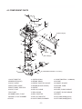
4-2 COMPORNENT PARTS
28
26
13
27
14
1
18
17
9
29
2 (With locktight)
19
16
22
30
5
23
7
24
3
4
2 (With locktight)
6
10
25
20
21
15
11 (TIGHTENING TORQUE 1.5~2.5N•m)
8
12
1.VALVE,THROTTLE
11.SCREW, DRAIN
21.GASKET(MATERIAL : ALUMINUM)
2.SCREW SET(VALVE)
12.SPRING, DRAIN
22.O-RING
3.VALVE, CHOKE
13.SCREW, THROTTLE ADJUST
23.GASKET, SPACER
4.SHAFT ASSY,CHOKE
14.SPRING(ADJUST SCREW)
24.SPACER, CARB
5.SHAFT COMPL,THROTTLE
15.SCREW
25.O-RING
6.VALVE, FLOAT
16.COLLAR, CHOKE
26.COVER, SLOW PASSAGE
7.PIN, FLOAT
17.SEAL,CHOKE
27.GASKET, SLOW PASSAGE
8.CHAMBER ASSY, FLOAT
18.SEAL,THROTTLE
28.SCREW
9.GASKET, FLOAT CHAMBER
19.COLLAR, THROTTLE
29.JET COML,MAIN(L)(#132)
10.FLOAT
20.VALVE COMPL,SOLENOID
30.JET COML,MAIN(R)(#133)
- 11 -
ISSUE EMD-EU6947
PRINTED IN JAPAN
February 2010