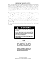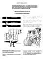
1
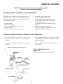
OPERATOR’S MANUAL
G3WD
7733-1006
July 2002
Upperstructure Starting S/N
8731229
Undercarriage S/N
Starting 87D024
Also Covers Upperstructure NP-411894
Undercarriage 86D104
Form #8606
Original Issue 1986
GRADALL
406 Mill Avenue S.W.
New Philadelphia, OH, 44663, USA
Telephone: (330) 339-2211
Fax: (330) 339-3579
IMPORTANT SAFETY NOTICE
Safe operation depends on reliable equipment and proper operating
procedures. Performing the checks and services described in this manual
will help to keep your Gradall Excavator in reliable condition and use of the
recommended operating procedures can help you avoid accidents. Because
some procedures may be new to even the experienced operator we
recommend that this manual be read, understood and followed by all who
operate the unit.
Danger, Warning and Caution notes in this manual will help you avoid injury
and damage to the equipment. These notes are not intended to cover all
eventualities; it would be impossible to anticipate and evaluate all
possible applications and methods of operation for this equipment.
Any procedure not specifically recommended by The Gradall Company
must be thoroughly evaluated from the standpoint of safety before it is
placed in practice. If you aren’t sure, contact your Gradall Distributor before operating.
Do not modify this machine without written permission from The Gradall
Company.
NYLON BRAKE LINES MAY BE DAMAGED
BY HEAT.
AVOID WELDING ON OR AROUND THE
MACHINE UNLESS BRAKE LINES ARE
PROTECTED FROM HEAT.
DISCONNECT BATTERY BEFORE WELDING
ON MACHINE.
NOTICE
The Gradall Company retains all
proprietary rights to the information contained in this manual.
The Company also reserves the
right to change specifications without notice.
Gradall is a registered,trademark for
hydraulic excavators, hydraulic material handlers and attachments manufactured by The Gradall Company.
The Gradall Company
406 Mill Avenue, S.W. New Philadelphia, Ohio 44663
INTRODUCTION
General
P I N Location
(Product Identification No.)
This manual provides important information to
familiarize you with safe operating procedures for
the Gradall Hydraulic Excavator.
Specify PIN and lot number when ordering parts
and when discussing specific applications and
procedures with your dealer. The PIN plate is
located on front center portion of upperstructure
frame.
Throughout this manual, the term “carrier” will be
used to designate the excavator undercarriage.
Related Manuals
Separate publications are furnished with the
Gradall to provide information concerning safety,
replacement parts, service manual with vendor
components and literature.
You must read and understand the Gradall Operation Manual and Safety Manuals before operating
the machine.
If you have any questions regarding the Gradall
Excavator, contact your Gradall Distributor; he
is thoroughly familiar with the unit and will be
happy to help you.
Serial Number Location
Operator Qualifications
The operator must hold a valid, applicable driver’s
license which requires acceptable age, vision,
hearing, manual dexterity and response. He must
also be in acceptable physical and mental condition
(not undergoing medical treatment or using drugs
or alcohol which would violate traffic laws.)
The carrier nameplate is located on the right side.
Be sure to specify the serial number (on nameplate)
when ordering parts and when discussing procedures and applications with your distributor.
Before driving the unit on the highway or operating
the excavator at a worksite, the operator must
familiarize himself with the machine by practicing in
a safe, open area not hazardous to people or
property.
Orientation
When used to describe locations of components in
the upperstructure, the directions front, rear, right
and left relate to the orientation of a man sitting in
the operator’s seat.
In relation to the carrier, front, rear, right and left
are determined by the orientation of a man sitting in
the driver’s seat.
2
SAFETY HIGHLIGHTS
Read and understand this manual, The Gradall Excavator Safety
Manual, CIMA Safety Manuals and all instructional decals and plates
before starting, operating or performing maintenance procedures on
this equipment. KEEP THIS MANUAL IN THE CAB.
Watch for these symbols; they are used
to call your attention to safety notices.
DANGER
This symbol indicates an extreme hazard which
would result in high probability of death or
serious injury if proper precautions are not
taken.
WARNING
This symbol indicates a hazard which could
result in death or serious injury if proper
precautions are not taken.
CAUTION
This symbol indicates a hazard which could
result in injury or damage to equipment or
property if proper precautions are not taken.
WARNING
Perform all “CHECKS & SERVICES BEFORE
STARTING ENGINE” and all “WARM-UP &
OPERATIONAL CHECKS” at the beginning of
your shift. Complete all required maintenance before operating or driving the unit.
Maintain three point contact with grab handles
and steps when climbing on and off the machine.
Never jump from the machine.
Repair or replace damaged steps and grab
handles.
3
CARRIER CAB CONTROLS
INSTRUMENTS AND INDICATORS
While in lower cab, the four wheel drive
can be engaged at any time in the lower
range. Use low R.P.M.
Do not move carrier while low air light is
glowing or while any auxiliary device is signaling a dangerous condition.
17. Fuel Gage
18. Front Axle Disconnect (4x4 only)
19. Ignition Key Switch
20. Parking Brake Button
21. Remote/Travel Switch
22. Dome Light
23. Windshield Wiper Speed Control
24. Windshield Washer Switch
25. Headlights Hi/Low Beam Switch
26. Brake Pedal
27. Acclerator Pedal
28. Emergency Engine Shut Off
29. Transmission Control Monitor
30. Turn Signal Control Lever
31. Hazard Flahser Switch
32. Horn Button
1. Heater Control Knob
2. Defroster Switch
3. Heater Switch
4. Headlights Switch
5. Pump Engagement Light
6. Converter Oil Pressure Gage
7. Display Light Panel
8. Air Pressure Gage
9. Water Temperature Gage
10. Transmission Shifter
11. Volt Meter
12. Oil Pressure Gage
13. Tachometer
14. Speedometer
15. Hour Meter
16. Converter Oil Temperature Gage
4
UPPERSTRUCTURE CAB
CONTROLS AND INSTRUMENTS
10. Engine Start Switch
11. Defroster Switch
12. Warning Buzz Light
13. Emergency Brake Knob
14. Air Pressure Gage
15. Forward/Reverse Travel Pedal
16. Steering Pedal
17. *Heater
*Optional
1. Throttle Lever
2. Boom In/Out & Swing Joystick
3. Boom Tilt Switch
4. Transmission Shift Up/Down Switch
5. Horn Switch
6. Boom Hoist & Bucket Joystick
7. Joystick On/Off Switch
8. Engine Stop Switch
9. * Windshield Wiper/Washer Switch
While working in upper cab, and any of
the display panel warning lights go on in
the carrier cab, a buzzer will sound in
both cabs. The operator should place
boom in rack, shut engine off and go to
lower cab and check all gauges and
determine reason for warning. Correct
malfunction before continuing to
operate.
5
CARRIER CAB DISPLAY LIGHT PANEL
Left turn signal (A) flashes when lever on steering
post is activated to indicate a left hand turn.
(GREEN)
If air pressure drops below 60 psi, (F) will light.
(RED). Check gauge.
If engine temperature reaches 210° F, (G) will light.
(RED). Check gauge.
Remote Control Indicator (B) is lit when the
remote rocker switch is depressed and all of the
pre-conditions are met. It will turn RED. At this
time the remote drive motor should be engaged and
the digging brakes applied and upper throttle
engaged.
If engine oil pressure drops to approximately 15 psi,
(H) will light. (RED). Check gauge.
If battery is below 12 volts, (J) will light. (RED)
Right turn signal (K) flashes when the lever on the
steering post is activated to indicate a right hand
turn. (GREEN)
If torque converter temperature reaches 250° F,
(C) will light. (RED)
If torque converter pressure drops below 200 psi,
(D) will light. (RED)
If head light switch is pulled and the foot button is
depressed, the high beam (E) will light. (BLUE)
NOTE: If any of the warning lights C, D, F, G or
H are on, a warning light and buzzer in the
upper cab will be activated.
CARRIER CAB CONTROLLER MONITOR
The Monitor is located to the right of the drivers
seat in the carrier cab. The Controller Monitor
provides range selection of the solenoid controlled
transmission in both travel and remote modes. It
also determines if remote or travel mode has been
S1
S2
S3
S4
C1
S5
S6
C2
selected by the operator and controls the machine
changeover to the mode selected. The Controller
Monitor has a panel of 14 lights which shows the
driver the status of the control system.
Transmission Solenoid #1 energized when lit.
Transmission Solenoid #2 energized when lit.
Transmission Solenoid #3 energized when lit.
Transmission Solenoid #4 energized when lit.
Solenoid Air Valve shifted to
travel mode when lit.
Transmission Solenoid #5 energized when lit.
Transmission Solenoid #6
energized when lit.
Solenoid Air Valve shifted to
remote mode when lit.
Neutral
Reverse
T1
T2
T4
Neutral Start Solenoid closed
when lit.
Travel alarms and back-up lights
energized when lit.
Low air condition exists when lit.
Engine not running when lit.
Hyd. Pump and Remote Motor
engaged when lit.
Malfunction
Indicator
Indicates a wire shorting between
the Controller Monitor and the
transmission shift solenoids. (Wires
S1 through S6)
6
SHIFT SOLENOIDS. A combination of these
lights tell which gear ratio has been selected. The
position of the gear selector lever on the dash
should match. The following will show the light
combinations while in the travel mode with high air
and the key turned on and engine running: C1 is lit
to show the travel mode.
S1 C1 S6 - First Travel Gear
S1 C1 S5 - Second Travel Gear
S2 C1 S6 - Third Travel Gear
S2 C1 S5 - Fourth Travel Gear
S3 C1 S6 - Fifth Travel Gear
S3 C1 S5 - Sixth Travel Gear
7
C2-T4. The following lights are lit when the remote
control switch is depressed to show the gear ratio
being used: The shift lever in the carrier cab will not
move. With engine running, and in remote,
lights C-2, T4 and Neut Start will be lit. C2 is
always lit.
.
S1 C2 C3 & T4 - First Remote Gear
S2 C2 C3 & T4 - Second Remote Gear
S3 C2 C3 & T4 - Third Remote Gear
8
NEUTRAL. Any time the shift lever in the carrier
cab is in the neutral position, the Neutral light will
be lit. The travel shifter must be in neutral
before engine can be started, or switched from
Travel to Remote and vice versa. If in Travel, the
C1 light will also be lit. If in Remote, the C2
Remote and the T4 Remote mode lights will
be lit.
REVERSE. The following show the lights which
are lit when in the 3 reverse positions. Reverse C4 is
lit to show it being in the reverse mode. The
Reverse C4 light and the C1 light will always
Be lit. CI indicates travel mode.
S1 S4 C1 & C4 - First Reverse Gear
S2 S4 C1 & C4 - Second Reverse Gear
S3 S4 C1 & C4 - Third Reverse Gear
9
MALFUNCTION INDICATOR. Indicates a wire
shorting between the Controller Monitor and the
transmission shift solenoids. It can also indicate that
the Controller Box is defective and should be replaced.
LOW AIR. If the system air pressure drops below
60 psi, T1 will light.
ENGINE OFF. Any time the engine is running, no
light will show at the T2 position. If the engine
stops, T2 position will be lit.
PUMP ENGAGED. When the remote switch is depressed, the air circuit shifts cylinders to engage the
hydraulic pump and the remote drive motor. If the
pump is engaged fully, the T4 light will be on.
10
CHECKS AND SERVICE
BEFORE STARTING ENGINE
(To be performed at beginning of each work shift)
Complete all required maintenance before operating unit.
1.
2.
3.
4.
5.
6.
7.
8.
9.
10.
11.
12.
Inspect visually for damage, leaks, vandalism & needed maintenance.
Test lights, turn signals, horn, & gages.
Inspect battery fluid level.
Make sure fire extinguisher is present.
Inspect level of windshield washer fluid.
Make sure remote switch is in travel position.
Check coolant level.
Check engine oil level.
Check fuel level.
Check for clean windows.
Check hydraulic oil level.
Lubricate as shown in manual.
Starting Diesel Engine from Carrier Cab
1. Be sure main transmission is in neutral, parking
brake is applied and engine stop handle is fully
depressed.
5. Warm up diesel engines at approximately one
third of governed speed until water temperature
reaches operating range (approximately
160°F./71°C).
2. Depress accelator pedal to a fast idle and hold in
this position.
NOTE: It may be necessary to use a cold weather
starting aid in temperatures below freezing.
3. Turn ignition switch fully clockwise to engage
starting motor. Release key immediately when
engine starts. If engine fails to start within fifteen
seconds, release key and allow starting motor to
cool for a few minutes before trying again.
Do not engage starting motor while flywheel or starting motor is rotating. Serious
damage could result.
4. After engine starts, observe oil pressure gage. If
gage remains on zero for more than ten seconds,
stop engine and determine cause. Correct before
restarting engine.
Stopping the Engine from Carrier Cab
Operate engine at idle speed for a few minutes
before turning it off. This allows engine coolant
and lubricating oil to carry excessive heat away
from critical engine areas.
Do not “gun” engine before shut down; this
practice causes raw fuel to remove oil film from
cylinder walls and dilute lubricant in crankcase.
To stop diesel engine, turn key to off.
11
Cold weather starting aids
Start in travel mode (pump not operating).
Diesel engine ignition is accomplished by heat
generated when fuel/air mixture is compressed
within the cylinders. Because this heat may be
insufficient to start a cold engine in cold weather,
the use of starting aids has become common
practice.
it would be impractical to attempt to provide
specific instructions for their use in this manual.
Carefully follow instructions furnished with your
starting aid.
If you use a starting aid employing ether or a
similar substance pay particular attention to
manufacturer’s warnings.
Because of the wide variety of starting aids available
Normal engine operation
When using engine braking power (downshifting
or releasing accelerator and permitting carrier to
“push” engine) to slow travel, take care to avoid
overspeeding the engine (exceeding governed
RPM). The governor has no control over engine
speed when engine is being “pushed” by carrier load.
Observe voltmeter, water temperature and oil
pressure gages frequently to be sure all engine
systems are functioning properly.
Be alert for unusual noises or vibration. When
an unusual condition is noticed, stop in a safe area
and shut off engine. Determine cause and correct
before continuing.
Select an appropriate gear ratio and use service
brake to assist in slowing travel down steep grades.
Early recognition and correction of unusual conditions can often prevent a major breakdown.
Apply load to engine gradually; shock loads are
hard on all drive line components.
Permitting the engine to labor under too great a
load for the gear ratio being used (lugging the
engine) will shorten engine life. Shift to the proper
gear ratio for conditions.
Use full governed engine speed for intermittent
duty only. For cruising or continuous duty use
approximately 85 percent of full governed engine
speed to maintain safe speed. This practice provides
increased engine life.
Avoid prolonged idling. Idling causes engine temperature to drop and this permits formation of
heavy carbon deposits and dilution of lubricating oil
by incompletely burned fuel. If the engine is not
being used, turn it off.
12
CHECKS AFTER STARTING ENGINE
(To be performed at beginning of each work shift)
Complete all required maintenance before driving
6. Observe water temperature gage. Proper operating temperature is approximately 160/
210° F. (71/104° C).
1. Check operation of windshield washer and
wiper.
2. Check all lights and turn signals for proper
operation.
7. Observe tachometer response to changes in
engine speed.
3. Check operation of heater and defroster.
8. Observe low air warning light. Light should
continue to glow until brake system pressure
reaches approximately 60 psi. Do not release
parking brake or move carrier while low air
warning light is still glowing.
4. Observe oil pressure gage with engine running
at operating temperature and speed.
5. Observe voltmeter indication of alternator output. Proper output is approximately 14 V. with
engine running at 2000 RPM.
9. Observe air pressure gages. Proper brake
. system pressure is 60/125 psi.
CHECKS BEFORE DRIVING
(To be performed at beginning of each work shift)
Complete all required maintenance before driving.
2. Check operation of steering while moving slowly
in first gear. Be alert for any increase in effort
needed to turn wheels and any unusual steering
response to normal steering effort.
1. Check operation of brakes by performing the
following procedure:
a. Position unit on level surface and apply
digging brake.
b. Position boom over rear of chassis and imbed
bucket in ground or against a solid object.
c. Apply down pressure with boom and pull and
push with boom while helper watches for
rotation of each wheel.
d. Rotation of any wheel during step c. indicates
brake failure on that wheel. Have any failure
corrected before driving the unit.
3. Check operation of horn and travel and back-up
alarm and any other signal devices.
PLAN YOUR TRIP
1. Plan a safe route to your destination.
2. Ask your supervisor about permit requirements.
3. Check on load & clearance limits along your route.
Dimensions for your unit are shown below:
Height - varies depending on attachment — measure unit to be sure.
Width (4 x 2). . . . 8'(2.44 m). . . . . . . . . . . . . . . . . . . . 100" on 4 x 4
Ground Clearance . . . . . . . . . . . . . . . . . . . . . . . . . . . . 10" (254 mm)
Weight - varies depending on options— weigh unit to be sure.
13
AIR CONTROLS
Air pressure is used to control the engine RPM
while driving the chassis or while operating the upperstructure.
shifts the cylinders at the pump and motor to cause
the jaw clutches to close and engage the pump and
motor.
To keep the pump and remote drive motor disengaged while driving the carrier, air cylinders are
used to actuate jaw type clutches. When the remote
toggle switch button on the dash is depressed, air
A limit switch is placed by the pump engage cylinder
to provide a visual warning light if the desired stroke
is not obtained and the pump does not fully engage
for upperstructure operation.
14
AIR THROTTLE CONTROL CIRCUIT
It is possible to control the engine RPM from the
carrier cab or the upperstructure cab.
Conventional Driving Mode:
Remote Control Driving Mode:
When driving the carrier, the floorboard accelerator is used to control the engine speeds from idle to
top governed RPM. The low idle is about 600 RPM
and the top is about 3l50 RPM (No Load) or 2800
RPM (Loaded).
When driving the carrier from the upperstructure in
the remote control mode a hand controlled air valve
is used (8). It is located on the cab floor to the left of
the operator’s seat. While in remote a low idle of 600
RPM and a high idle of 2700 RPM (No Load) or
2300 RPM (Loaded) can be obtained.
When starting the engine with low air, the spring on
the fast idle cylinder (1) works on the governor linkage to obtain a higher than idle speed to help build
up air pressure quickly. When the system builds up
to 55 psi, the piston in the fast idle cylinder moves to
counter the spring tension and the engine will run at
normal low idle speed.
The remote air circuit is activated when the remote
control switch (9) is depressed. Electrical current activates the Air Control Solenoid (10), routing tank
air over to the control port of the Air Pilot Valve (4).
Air pressure causes the Air Pilot Valve (4) to shift,
routing air to the upperstructure circuits thru centerpin (11) and the Hand Throttle Valve (8). When
the hand throttle is moved, controlled air is routed
back down thru the centerpin (11) and thru the
Shuttle Valve (5) to the Throttle Cylinder (6).
Normal depressing of the Accelerator Pedal (2)
routes air from the tank (3), thru the Air Pilot Valve
(4), thru a Shuttle Valve (5), to the Throttle Cylinder
(6). Movement of the piston in the throttle cylinder
moves the Fast Idle Cylinder and the linkage to the
engine governor (7). RPM is determined by the
amount of travel caused by pushing down on the
treadle valve pedal.
15
HYDRAULIC PUMP & MOTOR DISCONNECT
When driving the Gradall from the carrier cab, the
hydraulic pump and the hydraulic remote drive
motor is not engaged to the transmission.
REMOTE OPERATION: When the remote switch
(5) is activated the air solenoid (6) routes pilot air to
the air pilot valve (2). The plunger shifts and routes
air to the opposite ends of the pump and motor cylinders (3 & 4).
NORMAL DRIVING: When driving the chassis,
air from the tank (1) is routed thru the air pilot valve
(2) directly to the two cylinders for the pump and
motor (3 & 4) to keep them disengaged.
JAW TYPE CLUTCH: Each of the two cylinders
are connected to linkage which activates the jaw
type clutch (7). The illustration shows the jaws separated. Movement of the linkage which connects to
the cylinder rod causes the sliding half to move over
and engage the two halves.
BOTH DISENGAGED
16
BRAKE SYSTEM
The air brake system includes a service brake, an
emergency brake, a parking brake and a digging
brake.
Wear safety belt to avoid being thrown
from carrier driver’s seat during braking
emergency.
WARNING
Service brake
Do not operate carrier while low air indicator
is glowing. If light comes on while carrier is
moving, stop carrier in a safe area as soon as
possible. If carrier will not maintain proper
brake pressure notify maintenance personnel
immediately for repair of condition.
SERVICE BRAKE
APPLICATION
Emergency brake
The emergency brake functions only when air
pressure has been lost from some portion of the dual
brake system. Emergency brakes are applied by
normal foot pressure on the brake treadle.
The basic system includes two reservoirs to store
and furnish air pressure for service brake operation.
One reservoir supplies pressure to apply brakes to
the wheels of the front axle and the other supplies
pressure to apply brakes to the wheels of the rear
axle. Depressing the brake treadle causes air pressure to be applied to brake actuators of all wheels
simultaneously.
Emergency brakes will not stop carrier in
as short a distance as the service brakes.
EMERGENCY BRAKE
APPLICATION
(pressure lost in front)
Do not “fan” the brake valve treadle. A long
series of rapid brake applications can
reduce system pressure to a point where
effective service braking will be lost until
air compressor can restore pressure.
Operating pressure range for service brakes is 60 to
125 psi. A dual pressure gage is furnished to indicate pressure in front and rear portions of brake
system. The red needle shows pressure available for
rear axle brakes and the green needle shows pressure
available for front axle brakes. If pressure in either
portion of the system falls below safe operating
range, the low air indicator light will glow.
wheels of the front axle.
If air pressure is lost from the front portion of the
dual brake system, normal actuation of the brake
treadle valve will apply service brakes to the wheels
of the rear axle. There will be no braking on the
17
BRAKE SYSTEM (Con’t.)
If the air pressure gages indicate some system
pressure remaining, it may be possible to drive the
unit a short distance to remove it from a hazardous
position (use first gear only).
EMERGENCY BRAKE
APPLICATION
(pressure lost in rear)
If carrier cannot be moved, direct traffic around
carrier until warning flags, flares or lights can be
displayed.
Notify
proper
authorities
and
maintenance personnel as soon as possible.
Parking brake
Apply parking brake by raising parking brake
control knob. This causes air pressure to be vented
from spring chambers allowing springs to apply
brakes to wheels of the rear axle. Knob will raise
automatically if air pressure is lost from front and
rear portions of system.
If the air pressure is lost from the rear portion of the
dual brake system, normal actuation of the brake
treadle will apply service brakes to the wheels of the
front axle and cause a controlled application of
spring brakes to the wheels of the rear axle.
PARKING BRAKE
APPLICATION
After pressure is lost from one portion of the dual
brake system, there may only be enough pressure in
the other portion for one or two emergency brake
applications. When the available pressure has been
used the spring brakes will apply automatically.
EMERGENCY BRAKE
APPLICATION
(pressure lost in front and rear)
Release parking brake by depressing parking brake
control knob (system must be pressurized to release
parking brake).
AUTOMATIC
Digging brake
In the event air pressure is lost from both front and
rear portions of the system there will be an
automatic application of the spring brakes. They
will begin to apply as pressure drops to 60 p.s.i. (414
kPa) and there will be a complete application when
pressure decreases to 40 p.s.i. (276 kPa).
When activated, the digging brake is applied to all
wheels to hold the carrier stationary while the
excavator is digging.
Air pressure requirements for digging brake
application are not the same as those for the service
brake (60 to 85 p.s.i. - 414 to 586 kPa). If pressure
is lost after the digging brake has been applied,
emergency brakes will be applied automatically.
Because air pressure is required to release spring
brakes, an automatic application will remain ON
until air pressure can be restored.
18
Digging brake (Con’t.)
Remote control braking
DIGGING BRAKE APPLICATION
The digging brake is applied by the remote switch
in the carrier cab. The digging brake will be
released and reapplied automatically as travel
pedal in upperstructure is actuated and released.
Do not activate remote switch while
traveling. See page 23 for preparing carrier
for remote operation.
An emergency brake control is located in the
upperstructure cab. This control is to be used in
case of failure of the automatic digging brake. If
digging brake fails to apply when travel pedal is
released, raise emergency brake control to apply
emergency brake. Notify maintenance personnel
immediately for repair of digging brakes.
Apply upperstructure emergency brake when leaving upperstructure cab.
.
As the remote switch is depressed, the digging
brakes are automatically applied. Anytime the
remote signal light is lit, the brakes are applied,
unless traveling in remote.
19
STEERING SYSTEM
Conventional steering
Remote control steering
The power steering system provides low effort
steering under normal conditions and greater
control in the event of a blowout or soft ground.
“Road feel” is similar to that of a conventional
manual steering system.
Your unit is equipped with a travel/steering pedal
in the upperstructure cab. The engine must be
running to provide power for remote control
steering.
Regardless of upperstructure position on carrier,
depressing left side of pedal turns wheels to left;
depressing right side of pedal turns wheels to right.
Use of power steering while carrier is
stopped causes unnecessary stress on
system components and can cause
serious damage to system.
When not held in a left or right steering position,
the steering pedal will return automatically to its
neutral (non-steering) position. Be sure upperstructure cab is kept free of equipment and foreign
material which could jam steering pedal in a
steering position.
Holding steering wheel in full left turn or
full right turn position will cause system to
overheat. This can cause steering pump to fail.
Rotation of the carrier steering wheel will occur
during remote operation. KEEP CLEAR!
Be alert for any increase in effort needed to
steer. If any difference is noted, notify
maintenance personnel immediately for
correction. If power assist feature should
fail for any reason IT WOULD BECOME
VERY DIFFICULT TO STEER. For this
reason it is extremely important that you
NEVER TURN ENGINE OFF WHILE
TRAVELING.
In the event power steering fails, stop as
soon as possible. Do not drive unit until
problem has been corrected.
20
POWER TRAIN
The power train furnished on 4 x 2 carriers (units
having one driving axle at rear) include the engine,
torque converter, power shift transmission and the
rear axle. It includes the drive shaft between the
transmission and the rear axle.
The power train furnished on 4 x 4 carriers (units having
both front and rear driving axles) include the
engine, torque converter, power shift transmission
and the front and rear driving axles. The
transmission is moved back to the center portion of
the frame and drive shafts are used to connect it with
the engine and the two axles.
Torque Converter
Torque converter oil temperature and oil pressure
gages are provided to monitor torque converter
operation.
There are no operator controls for the torque
converter. It functions automatically to permit
starting from a standstill in any transmission speed
range.
POWER SHIFT TRANSMISSION
The power from the engine is transmitted to the
Shift-O-Matic through a torque converter. The use
of the torque converter has two distinct
advantages; (1) the converter is essentially a fluid
drive, there being no direct mechanical connection
between the engine and transmission assembly.
This feature creates a very smooth and shock-free
drive eliminating engine stalling. (2) The converter
multiplies torque during heavy pull-down loads.
When loads are light, the converter transmits the
engine power directly at almost engine speed, and
there is no torque multiplication. The net result is
an action like a transmission, with infinitely
variable and automatic speed ratios. The need for
shifting gears, although present, is greatly reduced.
The Series 2000 Shift-O-Matic is a six speed
forward, three speed reverse transmission.
Forward motion, reverse motion, and the speeds
are obtained through the use of electrically
controlled solenoids and hydraulically actuated
multiple disc clutches. These clutches are power
absorbing members that can be engaged at full
engine power. Shifting under full engine power
makes this a full power shift for the forward and
reverse motion in all speeds.
The clutches in these units are hydraulically
applied and spring released. Because the clutches
are hydraulically controlled, there is automatic
compensation for normal wear, which eliminates
the need for adjustment. Each clutch uses a
composition friction plate and a polished steel
reaction plate.
21
Downshifting
During normal driving there are times when it is
necessary to downshift (shift from one gear or range
to the next lower gear or range) to decrease carrier
speed or increase carrier power. The procedure for
downshifting is described below.
Never downshift when carrier speed will
cause engine to overspeed in next lower
gear or serious damage to engine may
result. Use service brake to slow carrier to
proper speed for downshift if necessary.
KEEP CARRIER IN GEAR WHILE DRIVING; COASTING IS
DANGEROUS AND MAY CAUSE SERIOUS DAMAGE TO TRANSMISSION.
When to shift gears
Smooth timely shifting not only increases carrier
service life, it provides greater driving safety.
When load conditions cause a continuing loss of
engine speed, downshift to the next lower gear.
In lower gears use only enough engine speed to get
the carrier rolling easily. High engine speeds under
light load conditions waste fuel and cause excessive
and unnecessary noise. Use a little more engine
speed for each successive upshift until reaching
desired cruising speed.
In general, operate in a gear that will permit
acceleration.
Though it is permissible to use the braking power of
the engine when traveling downhill take care to
avoid overspeeding the engine (exceeding governed
RPM). The governor has no control over engine
speed when the engine is being pushed by the carrier
load. Select an appropriate gear ratio and use your
brakes to assist in slowing the carrier.
Avoid continuous operation at full governed engine
RPM. Cruising at governed RPM reduces engine
service life and provides no reserve power for
varying conditions. It is good practice to select a
gear
offering
desired
carrier
speed
at
approximately 85 percent of governed engine speed.
Reserve full governed RPM for conditions
requiring full power.
22
REMOTE CONTROL
NOTE: Remote control is to be used for positioning unit at
job site, not for over-the-road travel.
Preparing Carrier for Remote Control Operation
When the driver wants to stop the Gradall on the job
and operate the upperstructure, he switches to remote control of the carrier at the same time. The
following steps are taken:
6. Actuate the remote control switch.
A. A remote indicator will go on.
B. The controller lights will show air is OK.
C. The pump and drive motor are engaged.
D. The brakes are set.
E. The transmission shifts automatically into
first gear.
7. Release the parking brake button.
8. Turn key to on position. Engine will not start
until pump engagement light is off.
1. Stop the machine.
2. Set the parking brakes.
3. Place the transmission shifter in neutral.
4. Turn the engine off.
5. Turn the key on again, but don’t start engine.
Preparing Upperstructure for Remote Control Operation
1. Be sure controls in carrier cab have been
properly set for remote control operation
(above).
3. An air controlled throttle is provided to bring the
engine RPM up to full governed RPM for upperstructure operation.
2. Be sure travel and steering pedals are in neutral
position.
4. Be sure EMERGENCY BRAKE control is in
OFF position.
REMOTE CONTROLS IN UPPERSTRUCTURE
How to Start Engine from
Upper Cab.
1. Start engine by depressing green start button.
23
Precautions for Remote Control Operation
Never tow load using remote control drive.
Be sure of clear visibility in direction of travel;
use a signalman to compensate for blind spots.
Always give audible signal before moving unit.
Be sure upperstructure swing brake functions
properly before moving carrier in remote
control.
Never permit bucket to drag while moving unit.
Rotation of carrier steering wheel will occur
during remote operation. KEEP CLEAR!
Be sure of clear path for carrier, boom and
counterweight before starting to move. Be
especially watchful for overhead wires
traffic.
Be sure travel alarm functions properly.
Front Axle Lock Cylinders Automatically
Unlock in Travel.
Driving carrier from upperstructure cab
Avoid confusion! Before actuating remote control travel pedal, think about
the direction you are facing with respect to the direction the carrier is
facing. Confusion could cause you to travel in the direction opposite that
returns to neutral position when released.
Release pedal gently for a smooth stop.
1. Be sure controls in carrier and upperstructure
cabs have been properly set for remote control
operation (see previous page).
2. Be sure engine is running at full throttle. Carrier
speed is controlled by gear selection and amount
of pedal actuation.
4. The steering pedal controls right and left turns;
depress left side of pedal to turn left or right side
of pedal to turn right. Pedal returns to neutral
position when released.
3. The travel pedal controls carrier travel; depress
front of pedal to travel forward or rear of pedal to
travel in reverse. The digging brake is automatically released when the pedal is depressed
and applied when the pedal is released. Pedal
5. Use EMERGENCY BRAKE to stop carrier if
automatic digging brake fails. Lift control knob
to apply brakes. Brakes cannot be released until
pressure is restored and parking and emergency
brake control knobs are depressed.
Apply emergency brake before
leaving upper cab.
Shifting Gears While in Remote Control
It is possible to shift into your choice of the three
lower gear ranges while operating in remote control
from the upperstructure.
A rocker switch is provided on the joystick pedestal.
Pressing down one time on the front of the rocker
will advance the shifter one gear higher. Press it
again and it will shift into third gear.
Pressing down on the rear of the shifter rocker
switch will reverse the action and shift down one
gear at a time.
The shifting of these three gears can be done while
the machine is moving.
24
Preparing Upperstructure for Conventional Carrier Operation
1. Test brakes (refer to page 11).
4. Allow engine to cool by running at idle speed for
a few minutes. Stop engine.
2. Retract boom and position boom in boom rest.
Secure boom using boom hold-down device as
necessary.
5. Be sure travel and steering pedals are in neutral
position.
3. Raise brake control knob to apply emergency
brake.
Preparing Carrier for Conventional Operation
3. Move the remote switch to the travel position.
This release the remote brakes, disengages the
hydraulic pump and the drive motor.
1. Shift main transmission to neutral.
2. Apply parking brake.
PARKING THE GRADALL
Precautions:
Avoid parking on slopes or near an excavation.
chine with boom in air.
Avoid parking on roads or highways. If It cannot be avoided be sure to display warning flags
during day and flares or flashing lights at night.
Park on level ground and block wheels.
If parking on a slope cannot be avoided, position unit at right angle to slope and block
wheels.
Position boom in boom rest; never leave ma-
Parking procedure
1. Using service brake, stop unit in appropriate
parking area.
5. Block carrier wheels as extra precautions against
rolling.
2. Set PARKING BRAKE to ON.
6. Fill fuel tank to minimize condensation. Remove
ignition key.
3. Allow engine to cool at idle speed for a few
minutes and then turn off.
7. Lock carrier and upperstructure cabs and install
protective window covers if available.
4. Shift transmission to first gear.
8. Disconnect batteries if unit is in an area where
tampering seems possible.
IN CASE OF TROUBLE
1. Park unit in a safe area, apply parking brake and block wheels. Display
warning flags, flares or flashing lights as necessary.
2. Contact supervisor and advise:
Nature of problem
Location of unit
Where you can be reached by phone
25
FRONT AXLE LOCK OUT CIRCUIT
(D) is mounted to the chassis frame on the right front
side. It functions automatically to keep the oil
locked in the two cylinders and prevent cylinder
movement while the carrier is in the remote control
mode and the dig brakes are set. When the units is in
the normal travel mode, the cylinder ports are joined
and connected to the reservoir dump and movement
of the cylinders can take place.
The G3WD is equipped with an automatic front
axle lock out system. It provides a positive lock between the front axle and the chassis frame while
digging. With improved stability while digging.
Two hydraulic cylinders (A) are installed between
the frame (B) and the front axle (C). A lock out valve
Do Not Pick & Carry Over Side
26
A TYPICAL GRADALL DIGGING CYCLE
1. Position unit for efficent digging cycle.
3. Start and warm up engine and hydraulic oil and
then move throttle lever to full throttle position.
2. Stop engine and secure door and windows in
upper cab to desired position for ventilation.
Remote boom hold-down device.
4. Move JOYSTICK rocker switch to ON position.
Always operate with engine at full throttle
to keep cylinders full of oil to prevent unexpected machine movements.
Avoid accidental actuation of the controls.
Always stop engine before repositioning
door and windows.
For deep or near vertical digging, position
machine to dig over right side of carrier. If
boom is lowered more than 68° below
horizontal over the left side, the boom cradle
will contact hydraulic reservoir.
Practice with joystick controls in a safe. open area.
Test your controls before operating. The control
pattern illustrated is the standard Gradall control
pattern. If your machine controls have been
modified to any other pattern, be certain you are
familiar with their functions before operating and
ensure that control diagram in cab is changed to
show the actual pattern.
Joysticks return to neutral position when released.
27
A TYPICAL GRADALL DIGGING CYCLE
5. Pull back on left joystick (A) to raise boom from
boom rest. Be sure to raise boom far enough to
clear all obstructions.
6. Move right joystick to left (G) to swing left or to
right (H) to swing right to digging site.
7. While pushing right joystick forward (F) to
extend boom, push left joystick forward (B) to
lower boom to position for start of cut.
8. Move left joystick to left (C) to open bucket or to
right (D) to close bucket for correct penetration.
Teeth should angle downward slightly (about
(5°). Angle may be greater for soft digging.
28
A TYPICAL GRADALL DIGGING CYCLE
9. If required, press left side of tilt switch (I) to tilt
counter clockwise or right side of switch (J) to
tilt clockwise.
10. While pushing forward on left joystick (B) to
lower boom and force bucket into ground, pull
back on right joystick (E) to retract boom and
fill bucket.
11. As bucket is filling, jog left joystick forward (B)
to lower boom and maintain depth of cut. At
same time jog left joystick to left (C) to open
bucket and maintain proper bucket angle.
12. When bucket is full or when boom is fully
retracted, move left joystick to right (D) to close
bucket. At same time pull left joystick back (A)
to raise boom. Raise boom only far enough to
clear obstructions.
29
A TYPICAL GRADALL DIGGING CYCLE
14. Move left joystick to left (C) to empty the
bucket.
13. Move right joystick to right (H) to swing right
or to left (G) to swing left to dump site. If
necessary, extend boom by pushing right
joystick forward (F).
15. Move right joystick to left (G) or right (H) to
align boom for next cut. Repeat steps 7 thru 15.
30
LIFTING AND POSITIONING A LOAD
Precautions
Do not depend on machine tipping as a warning of
overload. Some load ratings are based on hydraulic
lift capacity, not stability.
Do not travel with a suspended load. Excavators are not designed for pick and carry lifts.
Hydraulic relief settings must be correct when lifting
and positioning loads.
Sudden swing braking can cause unexpected
movement of the load and tip the machine.
Suspend loads only as shown. Passing load line over
bucket can cause uncontrolled movement of load.
Be sure tires are properly inflated before handling a
load.
Always operate at full engine RPM when handling a
load. This keeps cylinders filled and prevents
unexpected machine movements.
Keep load line vertical. Side loads can cause
structural damage and tip the machine.
Do not lift a load if unit has a boom extension
attached.
Keep everyone clear of machine (especially the
boom and suspended load). Use guide ropes to
position load.
Be thoroughly familiar with excavator hand signals
(shown at end of manual).
Lock out cylinders automatically unlock
in travel.
Load Attachment Point
Never pass load line over bucket. Relief valves in
bucket circuit could cause unexpected, dangerous
movement of the load. Bucket linkage could also be
damaged.
With bucket/adapter resting on ground, position
hook in tool eye as shown. Open bucket/adapter far
enough to prevent accidental disengagement of
hook. Be sure hook is not too large to fit between
tool eye and adapter.
SECURING BOOM/BUCKET
FOR TRAVEL
Position boom in boom rest and secure with boom
tie-down.
31
General
Planning A Lift
The excavator can lift and position loads safely
ONLY IF YOU PLAN THE LIFT PROPERLY.
1. Determine the weight of the load. Weight of
slings, chains and auxiliary lifting devices must
be added as part of the load. Refer to lift capacity
chart for weight adjustment required for bucket.
Failure to plan a lift properly can cause
death or serious injury.
NOTE: Lift capacities are based on machine being
on a firm level surface and also on load being freely
suspended as shown.
There is a great lift capacity difference between the
excavator ’s best and worst lift positions. Just
because it can lift a load from one point does not
mean it can safely move the load to any other point.
2. Move the machine to the best probable position
for making the lift.
3. Perform an unloaded trial run of the lift to
determine maximum load radius required and
maximum boom height and depth required to
complete the lift.
For example, the best lifting position is with the
excavator level and the boom fully retracted and
horizontal. Assume that you have just lifted the
maximum rated load from a truck with the unit in
this position. You can swing, but the only other
thing you can safely do with the load is put it back
on the truck. Lowering, or extending the boom can
exceed the rated capacity of the unit.
Measure load radius from the center of the rear axle
to the vertical load line and add 34" (distance from
axle to center of rotation).
The “common sense” and “feel” an experienced
operator might apply in regard to “tipping loads”
DOES NOT APPLY to loads limited) by hydraulic
lift capacity. Some loads shown on the chart in cab
are Hydraulic Lift Capacities. Exceeding these
capacities can cause a relief valve to open allowing
the load to fall, or in some cases, the machine to tip.
Measuring Load Radius
To avoid exceeding capacities, the entire lift must be
planned.
Measure boom height/depth from bucket adapter
pivot shaft to ground level (same plane as bottom of
tires). Be sure to allow for length of sling and height
of load.
Positioning Machine For A Lift
Before discussing the steps in planning a lift, let’s
consider the most favorable excavator positions for
making a lift.
4. Refer to lift capacity chart column for the
required load radius. If the required radius falls
between columns, use the column for the next
larger radius.
The shorter the load radius the greater the lift
capacity. Position the unit to minimize boom
extension while keeping a safe distance from
obstructions and excavations.
5. Check the appropriate capacities for the required
boom height and depth. The smaller of these
capacities is the maximum load permitted for lift
conditions.
Position the unit to minimize boom travel above
and below horizontal. For example, it may be
necessary to use a short sling to move a load from
a truck to the ground. Then use a longer sling to
position load in an excavation.
To determine practical working load limits the
operator must also consider wind, hazardous
conditions, experience of personnel and proper
load handling.
Finally, position unit for maximum visibility. If
conditions do not permit a clear view of the load
through entire lift, use a signal man.
Keep tires properly inflated. You have
more stability over the rear and less over
the side.
32
HOW TO EXTEND THE SLIDE-A-BOOM
.
1. Start engine. Position the upperstructure with
the boom over the right or left side of the
carrier. Extend the telescopic boom four feet and
place the bucket edge LEVEL into the ground.
Stop the engine.
6. Place the four 1" cap screws removed from the
front stop blocks into the rear stop blocks.
Tighten these four cap screws.
7. Tighten the four cap screws that hold the two
mounting brackets.
2. Using a 1-1/2" wrench, remove the four 1" cap
screws from the stop blocks.
8. To obtain adequate bolt torque, use a cheater
bar with the 1-1/2" wrench or socket. A 3'
cheater bar should be enough to obtain approximately 200 ft-lb of torque on the bolts at
the mounting brackets and about 600 ft-lb of
torque on the bolts at the stop blocks. Use a
torque wrench.
3. On the left side of the boom, loosen the four
1" capscrews which hold the two boom
mounting brackets. (These bolts should
be loosened as far as possible without
removing them.)
4. Lubricate slide areas of boom, if needed.
9. The boom is now in the extended position and
ready for digging.
5. Start the engine in the upper cab, and engage
the off-on switch activating the joysticks.
Make sure bucket is level and wedged into the
ground. Pull back on the boom in-out joystick.
The boom should start sliding. Continue sliding
the boom until contact is made against the rear
stop blocks. Stop the engine.
HOW TO RETRACT THE
SLIDE-A-BOOM
Reverse the above process, except use the boomout joystick when retracting the boom.
Correct torque is important. Do not over torque
under torque bolts
33
ATTACHMENT INSTALLATION
Keep boom in fully extended position
while installing bucket. Stay clear until
bucket adapter has been fitted tobucket as
shown in step 2.
Digging with a loose or an improperly
fitted bucket can shear adapter bolts and
cause excessive wear.
1. Position bucket adapter above bucket tube as
shown and lower boom until concave section of
adapter contacts bucket tube.
2. Move adapter toward “Bucket Close” position
until outer end of adapter contacts bucket.
3. Install adapter wedge bolts, washers and nuts and
tighten finger tight.
4. Raise boom slightly until bucket just clears
ground and tighten nuts. Check often to be sure
nuts remain tight.
6. Check to be sure bucket travel is limited by stops
when opening and by bucket tube when closing
- NOT by cylinder bottoming.
Never fully extend bucket cylinder without
a bucket installed or cylinder rod will be
damaged.
5. Position bucket linkage as desired.
34
EXCAVATOR HAND SIGNALS
Standard Signals - When excavator work conditions
require hand signals, they shall be provided or
posted conspicuously for the use of both signalman
and operator. No excavator motions shall be made
unless signals are clearly understood by both
signalman and operator.
Spccial Signals - When signals for auxiliary
equipment functions or conditions not covered are
required, they shall be agreed upon in advance by
the operator and signalman.
Instructions - When it is desired to give instructions
to the operator other than provided by the
established signal system, all excavator motions
shall first be stopped.
RAISE LOAD VERTICALLY - With either forearm
vertical, forefinger pointing up, move hand in small
horizontal circle.
LOWER LOAD VERTICALLY - With either arm
extended downward, forefinger pointing down,
move hand in small horizontal circle.
MOVE LOAD IN HORIZONTALLY - With either arm
extended, hand raised and open toward direction of
movement, move hand in direction of required
movement.
MOVE LOAD OUT HORIZONTALLY - With either
arm extended, hand raised and open toward
direction of movement, move hand in direction of
movement.
RAISE BOOM - With eitherarm extended horizontally, fingers closed, point thumb upward.
LOWER BOOM - With either arm extended horizontally, fingers closed, point thumb downward.
EXTEND TELESCOPIC BOOM - With both hands
clenched, point thumbs outward.
RETRACT TELESCOPIC BOOM - With both hands
clenched,
point
thumbs
inward,
SWING - With either arm extended horizontally,
point with forefinger to direction of swing rotation.
SWING - With either arm extended horizontally,
point with forefinger to direction of swing rotation.
OPEN BUCKET - Hold one hand oen and staionary. Rotate other hand in small vertical circle with
forefinger pointing horizontally at open hand.
35
CLOSE RUCKET - Hold one hand closed and
stationary. Rotate other hand in small vertical circle
with forefinger pointing horizontally at closed hand.
MOVE SLOWLY - Place one hand motionless in
front of hand giving motion signal. (Raise load
slowly is shown.)
THIS FAR TO GO - With hands raised and open
inward, move hands laterally, indicating distance to
go.
STOP - With either arm extended laterally, hand
open downward, move arm back and forth.
EMERGENCY STOP - With both armsextended
laterally, hands open downward, move arms back
and forth.
STOP ENGINE - Draw thumb or forefinger across
throat.
IF YOU GET STUCK
If unit becomes stuck in soft ground you can use the
boom to help free it.
rear to prevent tipping) and imbed bucket in ground.
While actuating travel joystick in appropriate direction, extend or retract boom as required to help
push or pull unit to solid ground. Raise or lower
boom as necessary to keep rear wheels in proper
contact with ground.
Position carrier and upperstructure controls for
remote control operation.
Position boom over rear of carrier (centered over
36
G3WD GRADALL