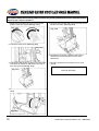
1
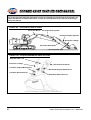
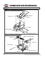
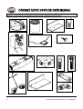
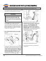
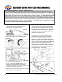
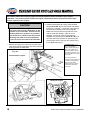
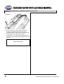
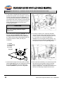
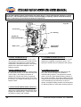
1ST GENERATION HENDRIX HYDRAULIC QUICK COUPLER
HENDRIX II HYDRAULIC QUICK COUPLER
PART # - UMCP-0902
Congratulations on your purchase of the Hendrix Hydraulic Quick Coupler. The Hendrix Coupler you have
purchased is a high quality, well-engineered product that will provide you with many years of good service.
The Hendrix Coupler will enhance the productivity and flexibility of your excavator. Please read this manual
and any accompanying materials thoroughly before installing, operating, or maintaining your Hendrix Hydraulic
Quick Coupler. If you have any questions, please contact your authorized Hendrix dealer.
The Hendrix Quick Coupler brings you the design, quality, and workmanship you expect from a Hendrix
product. Please pay particular attention to your personal safety while installing, operating, or maintaining this
unit, and remember to follow all applicable standard safety precautions.
The advantages of the Hendrix Coupler become apparent when a bucket or attachment change is necessary.
These advantages include:
1. A rotating locking mechanism with a locking lever that engages under and around the machine pin,
minimizing the chance of jamming unlike other trouble prone “wedge” lock systems that sometimes have
to be hammered open.
2. The positive locking system pushes against the back machine pin and away from the front pin, keeping the
coupler always tight.
3. High-strength compression spring(s) maintain constant pressure on the locking lever for protection against
a pressure loss in the hydraulic system.
4. A check valve that backs up the compression spring(s) and helps to prevent the possibility of an accidental
release of the attachment.
5. The Hendrix Coupler is equipped with a lifting eye. This lifting eye allows you to operate the machine as a
lifting device without the attachment, thereby gaining increased lifting power without bucket interference.
The Hendrix Hydraulic Quick Coupler operates on the excavator’s low-pressure pilot system rather than the
main high-pressure system. Engaging an attachment is easier and safer using the low-pressure pilot system
instead of a system that uses pressure from the bucket cylinder of the excavator. The attachment can remain
on the ground and does not have to be curled in to take the machine over relief.
The Hendrix Coupler is designed to allow the operator to switch the attachments on a hydraulic excavator in a
minimum amount of time. The Coupler is mounted between the excavator arm and the excavating
attachment.
Realization of the Hendrix Coupler’s full potential will depend upon the following factors:
1. A careful examination and execution of the installation, operation, and maintenance instructions provided
in this manual.
2. A designation of responsibility by the user of the equipment for the appropriate training in the installation,
operation, and maintenance of the coupler and its systems.
3. The equipment owner and/or operator should lock out/tag out the machine to prevent accidental startup
before installation of the Hendrix Coupler is attempted.
4. All users should completely read this manual before attempting to install, operate, or maintain this coupler.
Thank you for purchasing our product. We are confident you will be pleased with its performance.
Hendrix Manufacturing Company, Inc.
P.O. Box 919
Mansfield, LA 71052
Phone – (318) 872-1660 Fax – (318) 872-1508 www.hendrixmfg.com
i
IMPORTANT NOTES
Hendrix Manufacturing Company, Inc. builds its hydraulic quick couplers to OEM
attachment specifications. The coupler is designed to work only with attachments that are
also built to OEM attachment dimensions. The critical dimensions are the Pin Center-toPin Center dimensions, the Stick Width, and the Pin Diameters. You should insure that
your attachments are built to these specifications before attempting to operate the
coupler. Additionally, you may encounter some attachments that have structural
interferences that prevent the coupler from properly engaging the attachment. You should
resolve any interference issues before attempting to operate your quick coupler. Hendrix
assumes no responsibility or liability for attachments that are not built to OEM
specifications and/or have structural interference problems. Any costs incurred to modify
attachments that do not conform to OEM specifications and/or have structural
interferences are solely the responsibility of the end user.
HENDRIX WARRANTY POLICY AND PROCEDURES FOR QUICK COUPLERS
Hendrix Manufacturing Co., Inc. (Hendrix) warrants all quick couplers against defects in
material and workmanship for a period of 6 months or 1000 hours, whichever comes first,
after delivery to an end user. This warranty is valid only with the original purchaser, and
proof of delivery date to the original purchaser is required.
Warranty claims must be made to Hendrix in advance of any repairs via a warranty claim
number and warranty claim form which can be obtained by contacting Hendrix. Warranty
claims without a warranty claim number will be rejected. Any product requested by
Hendrix to be returned for inspection must be done so with freight charges prepaid. This
warranty does not apply to any quick coupler that has been subjected to misapplication
and/or abuse, or modified in any way without written authorization from Hendrix.
This warranty covers only new and unused products manufactured by Hendrix. Products
manufactured by others are covered only by the warranties extended to Hendrix by it's
suppliers.
All products are wearable and expendable and as such, Hendrix assumes no responsibility
for normal wear. Further, it is the responsibility of the customer to follow normal
maintenance and operating procedures, including, but not limited to daily inspection for
routine hairline cracks. Any cracks should be repaired before further propagation occurs.
Warranty claims are subject to credit on the dealer's account. Hendrix reserves the right to
pass judgement on time allowed for repairs and the rate charged for repairs. Repairs done
by an outside source will be subject to warranty one time only-- subsequent failure of
repairs by an outside source is non-warrantable. Hendrix shall not be liable for down-time
by the customer, mileage costs, damaged equipment, or loss of productivity incurred by
the dealer or customer.
Hendrix specifically disclaims all warranties, express or implied, including but not limited
to implied warranties of merchantability and fitness for any particular purpose with
respect to Hendrix products.
© 2002 Hendrix Manufacturing Company, Inc. Mansfield, LA USA. All rights reserved. Any use of the editorial or pictorial
content of this publication is strictly prohibited without express written permission from Hendrix Manufacturing Company,
Inc. Mansfield, LA USA. Printed in the USA (09/02). Rev.1 Issued –09/02
ii
TABLE OF CONTENTS
PAGE
GENERAL INFORMATION
I
Warnings, Recommendations, & Precautions
II
Parts ID Charts
III
Recommended Welding Procedures
IV
Hydraulic & Electrical Specifications
3
4
9
10
INSTALLATION INSTRUCTIONS
I
Installation Preparation
II
Remove the Bucket or Attachment
III
Connect the Coupler to the Excavator Arm
IV
Install Hose Brackets
V
Hydraulic Hose Assembly
VI
Hydraulic Hose Routing
VII Control Valve, Filter, & Switch Box Installation
12
13
14
15
17
18
21
OPERATION & MAINTENANCE INSTRUCTIONS
I
Warnings & Precautions
II
Switch Box Overview
III
1st Generation Coupler Familiarization
IV
Hendrix II Coupler Familiarization
V
Engaging the Attachment
VI
Disengaging the Attachment
VII Lifting Loads with the Coupler Installed
VIII Maintenance Procedures
28
30
31
33
35
40
41
42
!
WARNING
!
Read, understand and follow all safety precautions and procedures found in the machine’s
operator’s manual before attempting any operation, inspection or maintenance of this
machine, its attachments and/or systems. Hendrix Mfg. Co. cannot anticipate every possible
circumstance that might involve a potential hazard. The warnings in this document and on
the product are therefore not all inclusive. If a tool, procedure, work method or operating
technique not specifically recommended by Hendrix Mfg. Co. is used, you must satisfy
yourself that it is safe for you and others. You should also ensure that the product will not be
damaged or made unsafe by the operation, lubrication, maintenance and/or repair procedures
you choose.
1
Hendrix Quick Coupler User Manual Rev. 1 GBH4-09/02
GENERAL INFORMATION
!
DANGER
!
Failure to comply with information in this Hendrix Quick Coupler User Manual may
result in injury, death, damage to property, and/or damage to the Quick Coupler.
Insure that all personnel have read and understand the information in this User
Manual before attempting to install, maintain, and/or operate the Hendrix Quick
Coupler.
2
Hendrix Quick Coupler User Manual Rev. 1 GBH4-09/02
GENERAL INFORMATION SECTION I – WARNINGS, RECOMMENDATIONS, & PRECAUTIONS
This section provides general information and recommendations needed before attempting to install,
operate, or maintain your Quick Coupler
SAFETY MESSAGE CLASSIFICATION
Safety Messages in this Manual are classified as follows:
DANGER – Indicates an imminently hazardous situation. If not avoided, this hazard will result in death or
serious injury.
WARNING – Indicates a potentially hazardous situation. If not avoided, this hazard could result in death or
serious injury.
CAUTION – Indicates a potentially hazardous situation. If not avoided, this hazard may result in minor or
moderate injury and/or damage to the coupler or machine.
Read these instructions thoroughly before
attempting to install, operate, or maintain your
Hendrix Quick Coupler.
Route all hoses and wires in a neat and orderly
manner. Secure the hoses and wires to other
machine components.
Before installing, unpack the Coupler and Coupler
Kit. Inspect the Shipper’s Bill of Lading to
determine that all items have been received.
Do not force any parts during assembly. If the
parts are properly aligned, the pins will go in easily
and the fittings will screw into the valves without
undue force.
Inspect all items for any damage or missing items
due to transit or handling. If some items are
damaged or missing, please contact your dealer.
Lubricate all pins. Always use the original
machine pins that came with the excavator to
attach the coupler to the dipperstick.
Insure that all items listed on the Coupler Kit
Component list (see Chart #5 in General
Information section) are included.
Verify that the coupler machine number on the
Serial Number ID Tag (Fig. 3-1) matches the
machine you are attempting to install the coupler
on.
All hoses should have enough slack to move when
powering the dipperstick or attachment.
Sort out all Coupler Kit Material and group the
components together by component type. Be sure
to group all bolts with their respective washers.
Familiarize yourself with the Coupler and Coupler
Kit components before installing, operating, or
maintaining your Hendrix Quick Coupler (see
Parts ID charts).
Insure that you have an ample supply of rags and
absorbent towels on hand for cleaning purposes.
QUICK COUPLER
USA PATENT NO. 5082389
HENDRIX MANUFACTURING COMPANY, INC.
MANSFIELD, LOUISIANA USA 71052
Fig 3-1 (Coupler Serial Number ID Tag)
Tighten all fittings securely and properly.
Insure that all hoses, lines, and fittings are clean,
open, and clear before connecting them to the
system.
3
Hendrix Quick Coupler User Manual Rev. 1 GBH4-09/02
GENERAL INFORMATION SECTION II – PARTS ID CHARTS
This section provides Diagrams and Charts to help you identify the components of the Coupler, the
Coupler Installation Kit, and the Excavator, as well as to help familiarize you with the terminology
used in this manual.
CHART #1 - Excavator Parts ID Chart
Excavator Boom
Excavator Arm Cylinder
Excavator Bucket Cylinder
Excavator Linkage
Excavator Arm (Stick)
Excavator Idler Link
CHART #2 - Coupler/Attachment Parts ID Chart
Excavator Idler Link
Excavator Linkage
Excavator Arm (Stick)
Link-Side Original Machine Pin
Stick-Side Original Machine Pin
Link-Side Attachment Pin
Stick-Side Attachment Pin
4
Hendrix Quick Coupler User Manual Rev. 1 GBH4-09/02
GENERAL INFORMATION SECTION II – PARTS ID CHARTS
Continued….
CHART #3 - 1st Generation Coupler Parts ID
Cylinder
Spring End Cap
Locking Lever
Springs
"C"-Casting
Casting Lifting Eye
Mechanical Lock Pin
CHART #4 - Hendrix II Coupler Parts ID
Cylinder w/ Integrated Spring
Back Lever
Front Lever
Cast Lifting Eye
"C"-Casting
5
Mechanical Lock Pin
Hendrix Quick Coupler User Manual Rev. 1 GBH4-09/02
GENERAL INFORMATION SECTION TWO – PARTS ID CHARTS
Continued….
CHART #5 - COUPLER KIT COMPONENT LISTINGS & DRAWINGS
FILTER COMPONENTS
Filter Head
Filter Element
2 X 2 X 1/4 Angle Bracket
1/4 X 20 X 3/4 Hex Head Bolts with Washers
PART NUMBER
1753144
20101
MB-F
1/4X20X3/4
#4N-212
1
1
1
2
#6N-3
1
1
1
2
#6N-412
1
1
1
2
CHART #
A
B
C
D
SWITCH BOX COMPONENTS
3-Light Switch Box Assembly
Buss 10 Amp Fuse
#8 X 1/2" Mounting Screws
PART NUMBER
CCBXR1020799-3
FUSE10
8X1/2MS
#4N-212
1
1
3
#6N-3
1
1
3
#6N-412
1
1
3
CHART #
E
F
G
CONTROL VALVE COMPONENTS
Hydraulic Control Valve (24V Vickers)
Mounting Subplate
1/4 X 20 X 3/4 Subplate Mounting Bolts
1025 Mounting Screws
Control Valve Wiring Harness
Control Valve Mounting Bracket
PART NUMBER
DG4V3S2CMU1H560
AD03SP-S6S
1/4X20X3/4SMB
BK-D03
HARNDIQD
MB-V
#4N-212
1
1
2
4
1
1
#6N-3
1
1
2
4
1
1
#6N-412
1
1
2
4
1
1
CHART #
H
I
J
K
L
M
FITTINGS & HOSES
#6 Reusable Female Hose Ends (Swivel)
#6 O-Ring X #6 JIC Male (90 degree)
#8 O-Ring X #6 JIC Male
PART NUMBER
BL06-06NJ
849FSO06X06
848FSO06X08
2700-06-06
2702-06-06
711BHSF06
6400-06-06
#6MB
HFS06
NHS114
BL04-04NJ
883FS06X04
841FS06
854FSO04X04
E7-04
#4N-212
18
5
2
2
2
4
1
2
125'
20'
4
2
2
2
10'
20
1
2
#6N-3
18
5
2
2
2
4
1
2
125'
20'
N/A
N/A
N/A
N/A
N/A
20
1
N/A
#6N-412
18
5
2
2
2
4
1
2
150'
20'
N/A
N/A
N/A
N/A
N/A
20
1
N/A
CHART #
N
O
P
Q
R
S
T
U
V
W
X
Y
Z
AA
AB
AC
AD
AE
#6 JIC Male X #6 JIC Male (Straight Bulkhead Fitting)
#6 JIC Male X #6 JIC Male (45 degree Bulkhead Fitting)
Nut for Bulkhead Fittings
#6 O-Ring X #6 JIC Male
Upper & Lower Bulkhead Fittings Bracket
#6 2500 psi Single Braid Hydraulic Hose
Protective Hose Sleeve
#4 Reusable Female Hose Ends (Swivel)
#6 X #4 Tube End Reducer
37 Degree Tube End Reducer Nut
#4 O-Ring X #4 JIC Male (45 degree)
#4 2750 psi Single Braid Hydraulic Hose
Wire Ties
Tubular Hose Retainer Bracket
#4 O-Ring X #4 JIC Male (90 degree)
4C50X-S
IMPORTANT - Hendrix makes every attempt to supply you with the fittings to install your quick
coupler. However due to the variety of excavators, you will be required to provide the brand specific
fittings needed to tie into the pilot pressure system and the hydraulic reservoir tank. Please see your
excavator dealer to obtain these fittings. Additionally, certain machines may require adaptation of
connectors. Please see your excavator dealer for any appropriate fittings.
6
Hendrix Quick Coupler User Manual Rev. 1 GBH4-09/02
GENERAL INFORMATION SECTION TWO – PARTS ID CHARTS
Continued….(Drawings for representation purposes only. Drawings are not to scale.)
A
B
D
C
E
F
G
H
I
L
M
J
K
N
O
7
Hendrix Quick Coupler User Manual Rev. 1 GBH4-09/02
GENERAL INFORMATION SECTION TWO – PARTS ID CHARTS
Continued….(Drawings for representation purposes only. Drawings are not to scale.)
P
Q
R
S
U
T
V
X - #4 Kit
W
Z - #4 Kit
Y - #4 Kit
AA - #4 Kit
AB - #4 Kit
AC
AD
AE
8
Hendrix Quick Coupler User Manual Rev. 1 GBH4-09/02
GENERAL INFORMATION SECTION III– RECOMMENDED WELDING PROCEDURES
This section lists the recommended welding procedures to follow when installing or maintaining
your Coupler.
HENDRIX High Strength Low Allow Steels require greater than normal precautions when welding. All
areas to be welded should be cleaned and properly aligned ( if a fit is involved). Minimize heat input and
welding time by using short stringer beads and weaving not over three (3) times the electrode diameter.
Remove slag after each pass, and peen the bead to relieve stress. Preheat the part(s) to be welded to
300 degrees F (150 degrees C) to 400 degrees F (200 degrees C). Cool slowly after welding, wrapping
with insulating blanket, if necessary, in cold weather. A localized post weld heat treatment with a
Rosebud torch should include at least two (2) inches minimum of the adjacent base metal and the weld.
This heat treatment should raise the temperature of the area heated to 400 degrees F (200 degrees C) to
500 degrees F (260 degrees C). Control of this step is critical to avoid embrittling the steel.
Remove paint from any surface to be heated or welded. Painted surfaces give off unhealthy gases when
heated or welded. Use a mask and proper skin protection when removing paint from any surface. When
removing paint by sanding, do not breath the generated dust. Protect yourself at all times. When using
chemical compounds to remove paint, make sure to use plenty of soap and water to rinse the surface to
be welded, since such chemicals will generate unhealthy gases when heated or welded.
Be sure to perform this work in a well-ventilated area.
The electrode to be used is E7018 (SMAW) or E7OT-1 (FCAW). Follow the manufacturer’s
recommendations about electrode storage and avoidance of moisture, and other contaminants. The
electrode manufacturer can also recommend shielding gases. Persons performing welding should follow
Government guidelines for personal protective equipment.
Place the welding ground cable within 3 feet(1 m) of the area to be welded.
Use proper welding protection.
9
Hendrix Quick Coupler User Manual Rev. 1 GBH4-09/02
GENERAL INFORMATION SECTION IV – HYDRAULIC & ELECTRICAL SPECIFICATIONS
This section lists the specifications for the hydraulic and electrical components of the Coupler
Installation Kit.
HYDRAULIC FILTER UNIT: Purolator Filter Assembly
Max Pressure: 200 psi (13.8 bar)
Filter Element: 20101
Flow Rating:
32 Gpm (121 L/min)
Temp. Range: -45 degrees F to 225 degrees F (-43 degrees C to 107 degrees C)
Element change clearance: 2.50 inches (65mm)
HYDRAULIC CONTROL VALVE: Vickers DG4V-3S-2C-M-U1-H5-60
Power Rating:
30W @ 24VDC
Fatigue Pressure: 5000 psi (350 bar)
System Pressure: Excavator Pilot Pressure Control System (Not to exceed 1000 psi)
SWITCH BOX ASSEMBLY:
Voltage Rating: 24VDC
Alarm Decibel Rating: 72 dbA
Wiring Harness: T4-2 SJT0W (TPE) 105 degrees C FT2 water resistant
HYDRAULIC HOSE
#6 Hose: Eastman HFS06 2500 psi Single Braid Hose (or equivalent)
#4 Hose: Eastman E7-04 2750 psi Single Braid Hose (or equivalent)
10
Hendrix Quick Coupler User Manual Rev. 1 GBH4-09/02
COUPLER INSTALLATION INSTRUCTIONS
The following section will guide you through the necessary steps to install your Hendrix Quick Coupler.
Please review the information provided in the "General Information Section" before attempting to install your
coupler. Pay close attention to all Safety Messages in the manual.
The Coupler Installation will require you to do the following basic steps. You will connect the coupler to the
end of the excavator's arm. You will route the hoses from the coupler up the excavator arm and boom, and
down to the engine compartment that houses the pilot pressure system. The Hendrix Quick Coupler
operates off of the low pressure pilot system. You will install the control valve and filter in the engine
compartment. This will provide easy access to the low pressure pilot system as well as protection from the
elements. Your Hendrix Quick Coupler comes with a 3-Light Switch Box that will be mounted in the cab of
the excavator.
HELPFUL HINTS BEFORE BEGINNING INSTALLATION:
A. Read through the entire installation section before beginning the installation.
B. Determine where you will need to mount the control valve and filter (these components are
mounted in the main engine compartment near the excavator's pilot pressure system).
C. Determine where you will need to mount the switch box (this item mounts in the excavator cab).
D. Make sure you have the proper fittings needed to tie into the pilot pressure system and the
hydraulic return system (these fittings are NOT supplied with the Coupler Installation Kit).
E. Check to determine if the Tubular Hose Bracket can be welded to the excavator's H-Link.
F. Determine the best route for running the hoses on the excavator (the hoses should not interfere
with other excavator components).
!
DANGER
!
Failure to comply with information in this Hendrix Quick Coupler User Manual may
result in injury, death, damage to property, and/or damage to the Quick Coupler.
Insure that all personnel have read and understand the information in this User
Manual before attempting to install, maintain, and/or operate the Hendrix Quick
Coupler.
11
Hendrix Quick Coupler User Manual Rev. 1 GBH4-09/02
INSTALLATION SECTION I – INSTALLATION PREPARTION
This section lists necessary preparation steps before beginning the coupler installation.
1. Place the excavator, coupler, and all tools and
supplies needed in an open, unencumbered work
area. Make sure that the machine and coupler are
on flat secure ground.
2. Inspect the coupler and all coupler kit components
for signs of damage.
3. Insure that the coupler kit is not missing any
components.
4. If any components are damaged or missing, notify
your dealer.
5. Familiarize yourself with the components of the
coupler (see Chart #5 in the General Information
section).
6. The coupler ships with a set of attachment pins.
REMOVE these attachment pins from the coupler.
These attachment pins are NOT case-hardened
pins and are designed to be used in the ears of
the bucket or attachment. DO NOT connect the
coupler to the machine with the attachment pins
that shipped with the coupler. You will use the
original pins that came with the excavator to
connect coupler to the excavator.
7. You are now ready to begin the coupler
installation.
CAUTION
Never allow a hydraulic line or component
to become contaminated. Contamination in
the hydraulic system can cause severe
system damage. Contact your excavator
dealer to obtain the proper caps and plugs
used on your model excavator.
CAUTION
Make sure you use the ORIGINAL machine
pins from your excavator to connect the
coupler to the arm of the excavator. DO
NOT use the attachment pins that shipped
with the coupler to connect to the arm of the
excavator.
12
!
WARNING
!
Avoid oil spills. Use containers, rags, and/or
absorvent towels to contain any oil leakage.
Dispose of all waste oils, fluids, lubricants,
and other hazardous waste properly.
!
WARNING
!
Always use the proper safety protection
such as: hard hats, work gloves, safety
shoes, and safety glasses when operating,
maintaining, or installing this equipment.
CAUTION
DO NOT CONNECT THE HENDRIX QUICK
COUPLER TO HYDRAULIC PRESSURES
EXCEEDING 1000 PSI. The Hendrix Quick
Coupler is designed to operate off of the
excavator's low pressure pilot system. Only
connect the coupler to the excavator's low
pressure pilot system.
!
WARNING
!
Hendrix Hydraulic Quick Couplers are
designed to be used only with a Hendrix
Installation Kit. Installing a coupler with
anything other than components from a
Hendrix Installation Kit results in an
unauthorized modification to the coupler.
Any unauthorized modifications may impair
function, affect performance, and affect the
life of the coupler, the excavator, and/or the
attachment. Unauthorized modification may
result in injury or death to personnel.
Hendrix disclaims any liability and
responsibility resulting from unauthorized
modification. Unauthorized modification
voids all warranties.
Hendrix Quick Coupler User Manual Rev. 1 GBH4-09/02
INSTALLATION SECTION II – REMOVE THE BUCKET OR ATTACHMENT
This section details the necessary steps to remove any existing attachment from the excavator before
beginning the coupler installation.
1. Make sure the throttle control is in the low idle
position. Start the engine (see Fig. 13-1).
Fig. 13-1
5. Remove both the stick and link pin from the arm-tobucket connection (see Fig. 13-5).
Fig. 13-5
2. Unlock the safety lever (see Fig. 13-2).
Fig. 13-2
6. Operate the excavator controls to remove the
excavator arm from between the ears of the
attachment.
3. Operate the attachment controls on the excavator
to position the bucket or attachment securely on
firm, level ground (see Fig. 13-3).
Fig. 13-3
7. Rest the excavator arm securely on firm, level
ground.
END OF SECTION
4. Remove the retaining bolts from the pins (see Fig.
13-4).
Fig. 13-4
13
Hendrix Quick Coupler User Manual Rev. 1 GBH4-09/02
INSTALLATION SECTION III – CONNECT THE COUPLER TO THE EXCAVATOR ARM
This section details the necessary steps to connect your coupler unit to the excavator’s arm.
1. Insure that the coupler is resting securely on firm
level ground. No pins should be in the coupler.
Fig. 14-2
CAUTION
Make sure you use the ORIGINAL machine
pins from your excavator to connect the
coupler to the arm of the excavator. DO
NOT use the attachment pins that shipped
with the coupler to connect to the arm of the
excavator.
2. If the attachment pins that shipped with the
coupler are still in the coupler, remove these pins.
You will NOT use these attachment pins to
connect the coupler to the excavator arm. These
attachment pins are to be used in the ears of the
bucket or attachment. You will use the original
pins that came with the excavator to connect the
coupler to the excavator arm.
5. Slowly operate the bucket cylinder on the
excavator to align the excavator’s pivot link hole
with the link-side of the coupler. Insert the link
machine pin. USE THE ORIGINAL LINK
MACHINE PIN THAT CAME WITH THE
MACHINE TO CONNECT THE COUPLER TO
THE PIVOT LINK. Use a rubber mallet to drive
the pin into place. A pry bar may be necessary to
help adjust the pivot link in order to ease
installation (see Fig. 14-3).
3. If your machine requires bucket o-rings, install
these onto the coupler bosses at this time (see
Fig. 14-1).
Fig. 14-1
Fig. 14-3
6. Secure the stick and link pins in place by installing
their respective retaining bolts and nuts.
4. You are now ready to connect the coupler to the
excavator arm. With the throttle control in the low
idle position, slowly operate the excavator controls
to align the stick pin hole to the stick-side of the
coupler. Insert the stick machine pin. USE THE
ORIGINAL STICK MACHINE PIN THAT CAME
WITH THE MACHINE TO CONNECT THE
COUPLER TO THE STICK. Use a rubber mallet
to drive the pin into place (see Fig. 14-2).
14
7. Your coupler has now been connected to the
excavator arm.
Hendrix Quick Coupler User Manual Rev. 1 GBH4-09/02
INSTALLATION SECTION IV – INSTALL HOSE BRACKETS
The Coupler Installation Kit includes several brackets to help you neatly route your hoses. These
brackets include 2 Bulkhead Fittings Brackets and the Tubular Hose Retainer Bracket. One Bulkhead
Fittings Bracket (Lower) mounts on the excavator arm near the arm idler connection point and helps to
route the hoses from the end of the excavator arm to the coupler cylinder. The other Bulkhead Fittings
Bracket (Upper) mounts on the top portion of the excavator arm underneath the excavator’s bucket
cylinder and helps to route the hoses up the arm of the excavator. The Tubular Hose Retainer Bracket
mounts on the inside of the excavator’s bucket linkage and helps to guide the hoses going from the
Lower Bulkhead Fittings Bracket to the coupler’s cylinder. The following steps will guide you through
the process of installing these brackets to the excavator.
1. With the excavator still sitting securely on firm,
level ground, rest the excavator arm in an
extended position (see Fig. 15-1).
Fig. 15-1
2. Place the throttle control in the low idle position
and turn the ignition key off (see Fig. 15-2).
Fig. 15-2
6. Disconnect the negative cable from the battery
terminal. Review the "Recommended Welding
Procedures" in the General Information Section.
7. You are now ready to attach the Lower Bulkhead
Fittings Bracket to the excavator arm. Remove
the fittings from the bracket before welding the
bracket to the excavator arm.
8. The location of the Lower Bulkhead Fittings
Bracket will vary depending on your specific
machine. For a general guideline, install the
Bracket 9” from the center of the excavator arm’s
idler pin. The angle of the bracket should be at
the 9” point approximately (see Fig. 15-4 & 15-5).
Remember, this is only a guideline and your
requirements may vary depending on your specific
excavator/arm combination. Weld the bracket
securely onto the excavator arm using E7016 or
E7018 welding rod, or equivalent.
3. Place the safety lever in the locked position before
leaving the cab.
Fig. 15-4
Fig. 15-3
4. Secure a “DO NOT OPERATE TAG” to the
operator’s console to inform users that the
machine is inoperable. See your excavator dealer
for the appropriate “Lock Out” tag.
Fig. 15-5
5. Release the hydraulic tank pressure by operating
release valve on the hydraulic tank.
15
Hendrix Quick Coupler User Manual Rev. 1 GBH4-09/02
INSTALLTION SECTION IV – INSTALL HOSE BRACKETS
CONTINUED….
9. You are now ready to attach the Upper Bulkhead
Fittings Bracket to the excavator arm. Remove
the fittings from the bracket before welding the
bracket to the excavator arm.
12. Install the bulkhead fittings into the Upper
Bulkhead Fittings Bracket. This bracket uses the
45 degree bulkhead fittings (Chart# 5 - R) and the
fittings are secured by the bulkhead nut (Chart #5 S). See Fig 16-3.
13. Install the bulkhead fittings into the Lower
10. The location of the Upper Bulkhead Fittings
Bulkhead Fittings Bracket. This bracket takes the
Bracket (Chart#5 - U) will vary depending on your
straight bulkhead fittings (Chart #5 - Q) and the
specific machine. For a general guideline, install
the Bracket approximately 20” to 24” from the
fittings are secured by the bulkhead nut (Chart #5 center of the bucket cylinder connection pin (see
S). See Fig. 16-3. If you have a #4N-212 kit, you
will need to install the #6 X #4 Tube End Reducer
Fig. 16-1). Remember, this dimension is only a
guideline and your requirements may vary
and Nut (Chart #5 - Y & Z) onto the end of the
depending on your specific excavator/arm
bulkhead fittings.
combination. Weld the bracket securely onto the
excavator arm using E7016 or E7018 welding rod,
Fig. 16-3
or equivalent.
S U Q
Fig. 16-1
S
U
R
U
11. You are now ready to mount the optional Tubular 14. You have now mounted the necessary brackets
and are ready to route the hydraulic hoses.
Hose Retainer Bracket (Chart #5 - AD). This
piece of tubing mounts to the inside of the bucket
H-Link. It is designed to guide the hoses and help
prevent hose chaffing. Position the tubing in the
center of the link and weld it securely using E7016
or E7018 welding rod, or equivalent (see Fig. 162).
Fig. 16-2
AD
16
NOTE - The Tubular Hose Retainer Bracket may
not work on all excavator H-Links. The main
objective for the bracket is to guide the hoses from
the Lower Bulkhead fittings to the Coupler cylinder
and to prevent hose chaffing. Some H-Links are
made of materials that are not suitable for welding.
Other H-Links may allow the hoses to slip through
them. Find a method that will properly guide the
hoses and prevent chaffing.
Hendrix Quick Coupler User Manual Rev. 1 GBH4-09/02
INSTALLATION SECTION V – HYDRAULIC HOSE ASSEMBLY
This section details the processes of making the hydraulic hoses required for the coupler installation.
Please refer to the next section for installation procedures for the hoses. Hendrix makes every attempt
to provide adequate lengths of hoses for your coupler installation. However depending on your
excavator, you may find you need extra hose. Please see the hose specifications listed on the coupler
kit component listing in the event you need extra hoses.
17
Hendrix Quick Coupler User Manual Rev. 1 GBH4-09/02
INSTALLATION SECTION VI – HYDRAULIC HOSE ROUTING
This section details the necessary steps to route the hydraulic hoses needed for your coupler
installation. The hoses must be routed from engine compartment (where they will tie into the pilot
pressure system) to the coupler.
CAUTION
The exact manner in which you need to
route your hoses will vary depending on the
specifics of your excavator. Please use the
following steps as a guideline only. Always
route all hoses in a manner that will prevent
interfering with other lines and equipment.
Be sure to secure all hoses to the excavator.
2. Install the 90 degree #6 O-Ring X #6 JIC Male
fittings (Chart #5 - O) into the Extend and Retract
Ports on the cylinder***. Route the hoses through
the excavator's linkage as shown in Fig 18-1.
Make sure the hose has enough slack to move
with the excavator linkage. Allow for some
flexibility. Protect all moving hoses with the
supplied hose guard sleeves (Chart #5 - W). The
next step offers a procedure for determining the
proper length of the hose from the coupler to the
Lower Bulkhead Fittings.
1. Before connecting any hoses, be sure the hoses
have been flushed completely with clean hydraulic
fluid to prevent contamination.
***PLEASE NOTE - If you
have a 1st Generation
Hendrix Coupler that uses a
#4N-212 Kit, install the 45
degree #4 O-Ring X #4 JIC
Male Fittings (Chart #5 - AA)
into the cylinder's extend and
retract ports.
Fig. 18-1
1st Generation Coupler
If you have a Hendrix II
Coupler that uses a #4N-212
Kit, install the 90 degree #4
O-Ring X #4 JIC Male
Fittings (Chart #5 - AE) into
the cylinder's extend and
retract ports.
O
Hendrix II Coupler
O
18
Hendrix Quick Coupler User Manual Rev. 1 GBH4-09/02
INSTALLATION SECTION VI – HYDRAULIC HOSE ROUTING
Continued….
3. In order to determine the proper hose length, cut
two pieces of hose and allow plenty of extra hose.
Install the hose fittings on one end only. Connect
the hoses to the coupler cylinder. Route the
hoses through the excavator linkage (see Fig. 181). Slowly operate the excavator controls so that
the coupler is curled in completely (see Fig. 19-1).
Pull the hoses tight to the Lower Bulkhead Fittings
Bracket. Release tension on the hoses so that
you allow the hoses to have a small amount of
slack even in the fully curled in position. Mark the
hoses, cut, and assemble the hose fittings on that
end.
!
WARNING
5. Next you will need to route the hoses from Upper
Bulkhead Fittings Bracket all the way back to the
engine compartment. Install a hose fitting on one
end and route the hose to the excavator's bucket
cylinder and then down the boom. Route the
hoses in a manner that will prevent interference
with other lines or equipment. Secure the hoses
to the machine using the plastic tie wraps supplied
in the coupler kit. Repeat this procedure for both
sides.
!
Be sure to eliminate any twisting of the
hoses before tightening the connections. Do
not put hands into moving excavator
linkages.
Fig. 19-1
Fig. 19-3
Fig. 19-4
4. After installing the lower hose running from the
coupler to the Lower Bulkhead Fittings bracket,
begin routing the remaining hose sections.
Measure and install the hose between the Lower
Bulkhead Fittings Bracket and the Upper Bulkhead
Fittings Bracket (see Fig. 19-2). Remember to
route the hoses in a manner that will not interfere
with other lines and equipment.
Fig. 19-5
Fig. 19-2
19
Hendrix Quick Coupler User Manual Rev. 1 GBH4-09/02
INSTALLATION SECTION VI – HYDRAULIC HOSE INSTALLATION
Continued….
Fig. 20-1
6. Carry both of your hoses all the way into the
engine compartment that houses the pilot
pressure system. Make sure you have plenty of
slack where the line ends in the engine
compartment. You will tie these two hoses into
the control valve, which will be installed in the next
section.
END OF SECTION.
20
Hendrix Quick Coupler User Manual Rev. 1 GBH4-09/02
INSTALLATION SECTION VII – CONTROL VALVE, FILTER, SWITCH BOX INSTALLATION
The Control Valve and the Filter Assembly for the coupler are installed in the engine compartment of
the excavator. These components will tie into the excavator's low pressure pilot system. Additionally,
mounting these components in the engine compartment offers protection from the elements. The
Switch Box is installed in the cab of the excavator and is used to operate the coupler.
Fig. 21-1
R
COUPLER CYLINDER
E
EXTEND
RETRACT
MOUNTING SUBPLATE LEGEND
P = PILOT PUMP
A = HOSE A
T = TANK
B = HOSE B
PILOT
PRESSURE
PUMP
P
B
A
MOUNTING SUBPLATE
T
TANK
SOLENOID
HYDRAULIC
RESERVOIR
FILTER
SWITCH BOX
WIRING HARNESS
RELEASE
LOCK
B
W
G
3 WIRE
LEAD
2 WIRE
LEAD
WIRING LEGEND
B = BLACK
W = WHITE
G = GREEN
W
TO EXCAVATOR'S 24 VDC SYSTEM
10 AMP FUSE LINKED
B TO SYSTEM
GROUND
1. Figure 21-1 shows the electrical and hydraulic schematic for the quick coupler. Please remember that the
following steps are a general guideline since all excavators are different. The objective for this section is
to mount the control valve (solenoid valve) and the 3 light switch box. The control valve ties into the pilot
pressure system and hydraulic reservoir tank in order to provide hydraulic flow to operate the coupler. The
3 light switch box is mounted in the cab of the excavator and is what the excavator operator uses to
control the action of the coupler. The 3 light switch box connects to the control valve via the provided
wiring harness. The switch box and wiring harness leads are color-coded to ease installation.
CAUTION
DO NOT CONNECT THE HENDRIX QUICK
COUPLER TO HYDRAULIC PRESSURES
EXCEEDING 1000 PSI. The Hendrix Quick
Coupler is designed to operate off of the
excavator's low pressure pilot system. Only
connect the coupler to the excavator's pilot
system.
21
CAUTION
BEFORE CONNECTING ANY HOSES, FLUSH
COMPLETELY WITH CLEAN HYDRAULIC
FLUID TO PREVENT CONTAMINATION.
Hendrix Quick Coupler User Manual Rev. 1 GBH4-09/02
INSTALLATION SECTION VII – CONTROL VALVE, FILTER, SWITCH BOX INSTALLATION
Continued….
2. In the engine compartment that houses the low
pressure pilot system of the excavator, mount the
Control Valve Mounting Bracket (Chart #5 - L).
You should weld the bracket in a place that does
not interfere with other excavator components but
allows easy access to the pilot pressure system.
Follow standard welding procedures when
mounting the bracket.
O
O
CAUTION
T
Protect all hydraulic hoses and electrical
wires while welding inside the engine
compartment.
3. Mount the Mounting Subplate (Chart #5 - I) to the
Mounting Bracket (Chart #5 - M) using the
supplied Subplate Mounting Screws (Chart #5 J). Please note the Mounting Subplate ports are
marked as follows to assist you with your
installation:
I
Fig. 22-2
5. Connect the Hoses to the Mounting Subplate.
You will connect the two hoses that run from the
coupler cylinder into Mounting Subplate ports A &
B. You need to run a hose from Mounting
Subplate port P to the Pilot Pressure Pump. You
will route a hose from Mounting Subplate port T to
the Hydraulic Reservoir Tank (see Fig. 22-3).
T = Tank
P = Pilot Pump
A = Hose
B = Hose
Fig. 22-1
I
J
M
4. Install three 90 degree #6 O-Ring X #6 JIC Male
fittings (Chart #5 -O) and one straight #6 O-Ring X
#6 JIC Male (Chart #5 - T) into the Mounting
Subplate (Chart #5 - I) as shown in Fig. 22-2.
22
Fig. 22-3
6. Mount the Filter Assembly in an area that provides
easy access to the hydraulic reservoir tank but
does not interfere with other equipment in the
engine compartment. The Filter is mounted in-line
between the Mounting Subplate and the Tank.
Hendrix Quick Coupler User Manual Rev. 1 GBH4-09/02
INSTALLATION SECTION VII – CONTROL VALVE, FILTER, SWITCH BOX INSTALLATION
Continued….
Fig. 23-1
IMPORTANT - Hendrix makes every attempt to supply you with the fittings to install your quick
coupler. However due to the variety of excavators, you will be required to provide the brand specific
fittings needed to tie into the pilot pressure system and the hydraulic reservoir tank. Please see
your excavator dealer to obtain these fittings. Additionally, certain machines may require adaptation
of connectors. Please see your excavator dealer for any appropriate fittings.
7. Route a hose from the Mounting Subplate port P
to the pilot pressure system. Refer to the
excavator's OEM hydraulic system diagram for
connection points. Figure 23-2 provides an
example of one method of tying into the pilot
pressure system. Newer excavator's may provide
auxillary ports for connections from aftermarket
attachments. Contact your excavator dealer's
service department if you need additional
guidance.
23
Fig. 23-2
Hendrix Quick Coupler User Manual Rev. 1 GBH4-09/02
INSTALLATION SECTION VII – CONTROL VALVE, FILTER, SWITCH BOX INSTALLATION
Continued….
8. After properly connecting your hoses from the
Mounting Subplate to the Coupler cylinder, the
pilot pressure pump and the hydraulic reservoir
tank, you are now ready to install your solenoid
control valve (Chart #5 - H) onto the Mounting
Subplate. You will use the four 1025 Mounting
Screws (Chart #5 - K) to connect the valve and
subplate (see Fig. 24-1).
Fig. 24-2
L
Fig. 24-1
K
H
9. Install the Wiring Harness (Chart #5 - L) onto the 10. Inside the cab of the excavator mount the 3 Light
Switch Box in an area that allows for easy access
control valve (see Fig. 24-2) The Harness is
but does not interfere with the operation of the
marked for the "Lock" side and the "Release" side.
excavator.
The "Lock" side of the harness should be
connected to the side of the Control valve where
the Extend line comes into the subplate. The
"Release" side of the harness should be
connected to the side of the Control Valve where
the Retract line comes into the subplate. Please
note that the Wiring Harness has 3 color-coded
leads (Black = Ground, White = Release, & Green
= Locked).
24
Hendrix Quick Coupler User Manual Rev. 1 GBH4-09/02
INSTALLATION SECTION VII – CONTROL VALVE, FILTER, SWITCH BOX INSTALLATION
Continued….
14. With the machine power on and no attachment
11. The Switch Box has two cables. The first cable
connected to the Coupler, place the Switch Box
has 3 leads (Black, White, and Green) and is
Selector switch to the “LOCK” position. The
approximately 20 feet in length. Route this cable
Green light on the Switch Box should illuminate
back to the engine compartment containing the
and the Coupler cylinder rod should extend. If the
control valve. Connect the 3 leads of the switch
cylinder rod retracts, then your connections are
box to the 3 leads on the Control Valve Wiring
installed in reverse. To rectify this situation,
Harness. You should match the color coded wires
reverse the wiring harness DIN connectors.
(Black-to-Black, White-to-White, Green-to-Green.)
Retest the installation by repeating this step.
You should make all wiring connections in
accordance with standard electrical practices.
Refer to SAE Standard J2030 - Heavy Duty
Electrical Connections Performance.
15. Verify that the Switch Box and the Coupler
12. The second cable on the Switch Box is
Cylinder operate according to Fig. 26-1 If the
approximately 6 feet in length and has 2 leads
Switch Box and Coupler Cylinder do not operate in
(Black and White). Connect the White lead to the
accordance with Fig. 26-1, recheck the installation
excavator's 24VDC system. Link with the supplied
of all electrical and hydraulic components and
10 AMP fuse (Chart #5 - F). Fused circuits on the
insure that they are installed in accordance with
excavator should be utilized where applicable.
the instructions in this manual. If the problem
Connect the Black lead to the system ground.
persists, please contact your dealer.
You should make all wiring connections in
accordance with standard electrical practices.
Refer to SAE Standard J2030 - Heavy Duty
Electrical Connections Performance.
13. After making all switchbox connections, test the
installation of the coupler. DO NOT CONDUCT
THE TEST WITH AN ATTACHMENT ON THE
COUPLER. REMOVE ANY ATTACHMENTS
BEFORE TESTING THE SWITCH BOX
INSTALLATION. Please Note - The Hendrix
Coupler is equipped with a mechanical lock pin.
Be sure to remove the mechanical lock pin before
performing this test.
!
DANGER
!
CONDUCT ALL TESTS AWAY FROM ALL
PERSONNEL. REMOVE ANY
ATTACHMENTS WHEN TESTING THE
SWITCH BOX INSTALLATION.
25
Hendrix Quick Coupler User Manual Rev. 1 GBH4-09/02
INSTALLATION SECTION VII – CONTROL VALVE, FILTER, SWITCH BOX INSTALLATION
Continued….
NEUTRAL
Fig. 26-1
NEUTRAL
NEUTRAL
ALWAYS OPERATE COUPLER IN LOCK POSITION
Once you verify that the Coupler Switch Box is operating properly you have completed the installation of
your Coupler. Before attempting to operate or maintain the coupler, thoroughly read and familiarize
yourself with the following Operation and Maintenance Section of this manual.
Please Note - The lights on the Switch Box indicate switch position ONLY. The lights DO NOT
indicate the position of the lever. You must allow the lever time to extend and retract after
placing the switch in the respective position. Before operating the machine with coupled
attachments, always verify that the lever(s) are properly engaged by following the steps listed in
the "Engaging the Attachement" section of this manual.
26
Hendrix Quick Coupler User Manual Rev. 1 GBH4-09/02
OPERATION & MAINTENANCE
INSTRUCTIONS
The following section will provide you the necessary information to operate and maintain your Hendrix Quick
Coupler. Please review the information provided in the "General Information Section" before attempting to
operate and maintain your coupler. Pay close attention to all Safety Messages in the manual.
!
DANGER
!
Failure to comply with information in this Hendrix Quick Coupler User Manual may
result in injury, death, damage to property, and/or damage to the Quick Coupler.
Insure that all personnel have read and understand the information in this User
Manual before attempting to install, maintain, and/or operate the Hendrix Quick
Coupler.
27
Hendrix Quick Coupler User Manual Rev. 1 GBH4-09/02
OPERATIONS & MAINTENANCE SECTION I - WARNINGS & PRECAUTIONS
This section provides warnings and precautions to be taken before operating and/or maintaining the
Hendrix Quick Coupler.
!
DANGER
!
Improper operation and maintenance of this
equipment could result in serious injury or
death. Read this operator's manual
thoroughly before operating and/or
maintaining this equipment.
CAUTION
The excavator's effective reach, as well as the
attachment tip radius are increased with the
Hendrix Quick Coupler installed. Keep in mind
that the attachment can come in contact with the
Boom, Arm, and Cab depending on the
Coupler/Attachment combination.
Be aware that the excavator's attachment range
of motion changes with the Hendrix Quick
Coupler Installed:
>>Increase/Decrease bucket dump angle
>>Increase/Decrease bucket curl forward angle
Read these instructions and safety precautions
thoroughly before operating or maintaining the
coupler.
Inspect the coupler and all coupler components
before beginning operation. Perform any necessary
repairs before operating the coupler.
Make sure the attachment is resting on the ground
and properly supported before performing any work
on the coupler.
Under normal conditions, all machine hydraulic
circuits are under extreme pressure. When
inspecting for leaks, use a small piece of cardboard,
wood, or metal to locate leakages. Small (pinhole)
leaks can be dangerous if contact with skin or eyes
is made. Wear approved safety glasses and/or face
shields, gloves, hard hat, safety shoes, and work
clothes during all inspection and maintenance
procedures.
Always wear protective equipment when performing
maintenance.
!
DANGER
!
Unauthorized modification to the coupler
and/or any coupler components may impair
function, affect performance, and affect the
life of the coupler, the excavator, and/or the
attachment. Unauthorized modification may
impair the safety of personnel and can
cause serious injury or death. Hendrix
assumes no responsibility for any
unauthorized modifications to the coupler
and/or coupler components. Unauthorized
modification voids the coupler's warranty.
!
DANGER
!
TEST ALL CONNECTIONS AWAY FROM ALL
PERSONNEL. NEVER SWING COUPLED
ATTACHMENTS OVER WORKERS' HEADS.
28
All coupler/attachment combinations should be
checked for possible interference before using. Any
interference problems should be corrected before
using the coupler. Ensure that the coupler engages
and disengages properly and easily.
All excavator operators should familiarize
themselves with all Coupler/Attachment
combinations before attempting to operate the
coupler. This should include, but not be limited to,
practicing engaging and disengaging each
attachment. Furthermore, when new attachments
are added to the machine’s fleet, the operators
should proceed with the same “familiarization”
process before they are used on the jobsite.
Never use the coupler without an attachment, except
when used for lifting.
Review all information in the General Information
section of this manual.
Hendrix Quick Coupler User Manual Rev. 1 GBH4-09/02
OPERATIONS & MAINTENANCE SECTION I - WARNINGS & PRECAUTIONS
Continued….
WARNING
!
!
Avoid oil spills. Use containers, rags, and/or
absorvent towels to contain any oil leakage.
Dispose of all waste oils, fluids, lubricants,
and other hazardous waste properly.
!
WARNING
!
Use safety protection such as: hard hats,
working gloves, safety shoes, and safety
glasses when needed to perform this job.
CAUTION
The operator may experience slow or
unexpected movement of functions when
operating with cold hydraulic oil. Likewise,
damage to the hydraulic components may result
due to the cold oil. Make sure to warm up the
hydraulic system before operation.
CAUTION
Never allow a hydraulic line or component to
become contaminated. This could cause severe
system damage. Contact an authorized machine
distributor to obtain proper caps and plugs to be
used on this machine.
CAUTION
Only operate the Coupler with the control box switch
in the LOCK position. The green light indicator will
illuminate when the switch is placed in the LOCK
position.
The buzzer alarm indicates a potential unlock
condition in the coupler. Do not attempt to operate
the attachment if this condition is present. Always
verify visually that the attachment is properly locked.
Make sure that the buzzer alarm functions properly
at all times.
Perform all connection tests before attempting to
operate the coupler.
Make sure to lubricate the Coupler daily with EP2
Lithium base type grease. Lubricate every 4 hours if
the coupler works under water.
Never use the Coupler as a prying tool.
Never use the Coupler as a clamping device.
Inspect the Coupler and all components each day.
Make any necessary repairs before operating.
Do not use the Coupler if it is severely worn. Make
sure to repair wear before resuming operation.
Check the spring preload daily on the 1st Generation
Coupler. Refer to Page 42 for spring preload
dimensions. Do not pre-load springs more or less
than the specification values. Also inspect the
locknut on the spring adjustment for tightness each
day.
DO NOT CONNECT THE HENDRIX QUICK
COUPLER TO HYDRAULIC PRESSURES
HIGHER THAN 1000 psi. The Hendrix Quick
Coupler is designed to operate on the low
pressure pilot system only.
!
WARNING
!
Maintenance work should be performed by
experienced and qualified personnel.
29
Hendrix Quick Coupler User Manual Rev. 1 GBH4-09/02
OPERATIONS & MAINTENANCE SECTION II - SWITCH BOX OVERVIEW
This section provides an overview of the function of the Switch Box.
The Hendrix Quick Coupler is controlled by the provided 3-Position Switch Box that mounts in the cab of the
excavator. The Switch Box functions as follows:
A. RELEASE POSITION
When the switch is placed in the Release Position,
the Coupler cylinder will retract. In the Release
Position the buzzer alarm will sound and the RED
light on the Switch Box will glow. The Release
Position should be used ONLY when changing
attachments. If the coupler is disconnected from
an attachment for any length of time, the selector
switch may be returned to the lock position to
silence the alarm.
C. LOCK POSITION
The Lock Position will extend the Coupler cylinder.
When the Coupler cylinder extends, the locking lever
will rotate and engage the attachment link pin. The
GREEN light will glow and the buzzer alarm will stop
when the switch is placed in the lock position. THE
SWITCH MUST BE PLACED AND REMAIN IN THE
LOCK POSITION WHILE OPERATING THE
EXCAVATOR WITH A COUPLED ATTACHMENT.
B. NEUTRAL POSITION
The Neutral position is used ONLY in the event of
a hydraulic leak in the coupler system (i.e. Coupler
Hose Breakage). In this position the buzzer alarm
will sound and the Yellow light will glow*. Under
no circumstances, should this position be
used for Coupler operation. In the neutral
position, hydraulic flow to the coupler is shut off.
Fig. 30-1
NEUTRAL
NEUTRAL
NEUTRAL
ALWAYS OPERATE COUPLER IN LOCK POSITION
Please Note - The lights on the Switch Box indicate switch position ONLY. The lights DO NOT indicate the position of the
lever. You must allow the lever time to extend and retract after placing the switch in the respective position. Before
operating the machine with coupled attachments, always verify that the lever(s) are properly engaged by following the steps
listed in the "Engaging the Attachement" section of this manual.
30
Hendrix Quick Coupler User Manual Rev. 1 GBH4-09/02
OPERATIONS & MAINTENANCE SECTION III - 1ST GENERATION COUPLER FAMILIARIZATION
The 1st Generation Hendrix Quick Coupler is built with a low profile design. It uses high-strength
castings in critical wear areas. The 1st Generation Coupler is built to OEM specifications. Please review
the following section to familiarize yourself with the coupler components.
1ST GENERATION COUPLER
C. PIN SUPPORT CASTING (1st Generation)
The pin support casting is located in the rear
mounting area of the coupler (see Fig. 31-1).
This area of the coupler was strengthened to better
accommodate most demolition tools such as
hydraulic hammers, concrete pulverizers, hydraulic
thumbs, and other tools.
CAUTION
All coupler/attachment combinations should be
checked for possible interference before
operating the coupler. Insure that the coupler
engages and disengages properly and easily
with each attachment.
Fig. 31-1
31
A. SPRINGS (1st Generation)
Constant pressure is maintained on the locking
lever by two compression springs. These springs
assist the hydraulic cylinder in keeping the locking
lever secured. Inspect daily to make sure that the
springs are set to their proper pre-load dimension
(see Page 42 ). After the pre-load dimension is
properly set, ensure that the adjusting bolt lock nut
is tightened so that it jams to the spring hanger.
Any broken or missing spring should be replaced
immediately. In addition, it is recommended that
the springs are replaced annually.
D. LOCKING LEVER (1st Generation)
The cast high-strength locking lever rotates under
the attachment link pin in the rear mounting area of
the coupler. The rotating mechanism is designed to
minimize the chance of jamming. When the pin is
seated properly in the lever, pressure from the
springs and cylinder locks the attachment link pin
between the pin support and the hexagon contact
points in the lever. Because the locking system
pushes away from the front pin, the coupler remains
tight, even as it begins to wear.
B. LIFTING EYE (1st Generation)
The High-Strength lifting eye is made from a Low
Alloy Cast steel and designed to handle the
machines lifting capacity. It is important to mention
that the excavator gains additional lifting capacity
in both, weight and height, and better visibility
when the coupler is used to lift the load without the
attachment. The closed lifting eye should not be
cut open or altered. An approved lifting shackle is
recommended for attaching cables or other safety
hoisting products.
E. CYLINDER CHECK VALVE (1st Generation)
The internal check valve is another safety feature
that backs up the compression springs in the unlikely
event of a hydraulic failure. Should a hose break, the
check valve will maintain constant pressure on the
attachment link pin. Once the attachment is
engaged, the locking lever can only be retracted by
applying positive pressure to the retracting port. This
is done by placing the control box switch to the
Release position.
Hendrix Quick Coupler User Manual Rev. 1 GBH4-09/02
OPERATIONS & MAINTENANCE SECTION III - 1ST GENERATION COUPLER FAMILIARIZATION
Continued….
E. MECHANICAL LOCK PIN (1st Generation)
Later model 1st Generation Hendrix Quick
Couplers are equipped with a mechanical locking
pin. This pin is inserted behind the Locking Lever
and is secured in place using lynch pins on each
end of the pin. If you have a coupler that does not
have a mechanical locking pin, Hendrix
recommends that you obtain and install the
mechanical locking pin. Please contact your
Hendrix dealer for details.
Fig. 32-1
LOCKING LEVER
LOCKING PIN
END OF SECTION.
32
Hendrix Quick Coupler User Manual Rev. 1 GBH4-09/02
OPERATIONS & MAINTENANCE SECTION IV - HENDRIX II COUPLER FAMILIARIZATION
The Hendrix II Quick Coupler is built with a low profile design. It uses high-strength castings in critical
wear areas. The Hendrix II Coupler is built to accept multiple pin spacing. Please review the following
section to familiarize yourself with the Hendrix II components.
HENDRIX II COUPLER
Fig. 33-1
Front Lever
"C"-Casting
Cylinder w/
Integrated Spring
Back Lever
Replaceable
Wear Pads
Lifting Eye
A. FRONT LEVER (Hendrix II)
The Hendrix II Coupler features a Front Lever.
The geometry of the Front Lever along with the
configuration and alignment of other coupler
components, hold the Front Lever in the closed
position even without the assistance of the
hydraulic cylinder.
D. CYLINDER W/ SPRING (Hendrix II)
The double-acting cylinder on the Hendrix II coupler
features an integrated compression spring. The
spring is included solely as a backup to the cylinder.
B. BACK LEVER (Hendrix II)
The cast high-strength back lever rotates under
the attachment link pin in the rear mounting area
of the coupler. The rotating mechanism is
designed to minimize the chance of jamming.
Because the locking system pushes away from
the front pin, the coupler remains tight, even as it
begins to wear.
E. LIFTING EYE (Hendrix II)
The High-Strength lifting eye is made from a Low
Alloy Cast steel and designed to handle the
machines lifting capacity. It is important to mention
that the excavator gains additional lifting capacity in
both, weight and height, and better visibility when the
coupler is used to lift the load without the attachment.
The closed lifting eye should not be cut open or
altered. An approved lifting shackle is recommended
for attaching cables or other safety hoisting products.
C. REPLACEABLE WEAR PADS (Hendrix II)
The Hendrix II Coupler features replaceable wear
pads on the coupler frame where the back lever
engages the attachment pin. These wear pads
are made of "Hardox 400" material.
33
Hendrix Quick Coupler User Manual Rev. 1 GBH4-09/02
OPERATIONS & MAINTENANCE SECTION IV - HENDRIX II COUPLER FAMILIARIZATION
Continued….
F. CYLINDER CHECK VALVE (Hendrix II)
The Hendrix II features a cylinder with an external
check valve allowing for easier access. Should a
hose break, the check valve will maintain constant
pressure on the attachment link pin. Once the
attachment is engaged, the locking lever can only
be retracted by applying positive pressure to the
retracting port. This is done by placing the control
box switch to the Release position.
END OF SECTION.
External Check Valve
Fig. 34-1
G. MECHANICAL LOCK PIN (Hendrix II)
All Hendrix II Couplers use a mechanical locking
pin that inserts through the "C"-Casting.
Fig. 34-2
Mechanical Lock Pin
34
Hendrix Quick Coupler User Manual Rev. 1 GBH4-09/02
OPERATIONS & MAINTENANCE SECTION V - ENGAGING THE ATTACHMENT
This section details how to properly engage an attachment with the Hendrix Quick Coupler.
!
DANGER
!
Failure to properly engage an attachment
can result in serious injury or death. THE
ATTACHMENT MAY DROP WITHOUT
WARNING IF THE COUPLER IS NOT
PROPERLY ENGAGED WITH THE
ATTACHMENT. Read this section carefully
and perform the following steps each and
every time you change attachments.
!
DANGER
!
ENGAGE ATTACHMENTS COMPLETELY
CLEAR OF ALL PERSONNEL.
TEST ALL CONNECTIONS AWAY FROM ALL
PERSONNEL.
NEVER SWING COUPLED ATTACHMENTS
OVER WORKERS' HEADS.
Fig. 35-2
1st Generation
Fig. 35-3
ATTACHMENT PARTS IDENTIFICATION
Hendrix II
Fig. 35-4
Fig. 35-1
CAUTION
1. Open the coupler lever by placing the control box
switch in the RELEASE position (see Fig. 352,3,&4). The buzzer alarm will sound and the red
light will glow. Allow the lever(s) time to retract
fully.
35
Do not hit the coupler's locking lever or force
the coupler on the attachment pin while in the
RELEASE mode. Always allow the lever(s)
time to fully retract.
Hendrix Quick Coupler User Manual Rev. 1 GBH4-09/02
OPERATIONS & MAINTENANCE SECTION V - ENGAGING THE ATTACHMENT
Continued….
2. Operate boom, arm, and bucket cylinders to
position the coupler at approx. a 45º angle on the
attachment's stick pin. Fully seat the coupler's "C"
casting on the stick pin as shown in Fig. 36-1.
CAUTION
Note - The Control Box switch should still be in the
RELEASE position while seating the coupler. The
coupler must be fully seated on the attachment's
link pin for the locking lever to properly engage
under and around the link pin.
4. After seating the coupler on the link pin, you are
ready to lock the coupler in place.
A. 1ST GENERATION COUPLER
The 1st Generation Coupler is locked into place by
engaging the attachment's link pin with the coupler's
locking lever. To engage the attachment's link pin,
place the Control Box switch to the LOCK position
(see Fig. 36-3). Placing the switch in the LOCK
postion will extend the coupler's locking lever (see
Fig. 36-4). The lever should engage under and
around the attachment's link pin. Please allow the
locking lever time to fully engage the pin. If the
locking lever does not engage under and around the
link pin, then you have NOT properly engaged the
attachment.
Fig. 36-3
Fig. 36-1
3. Seat the coupler onto the attachment's link pin by
curling the coupler in toward the machine (extend
the machine's bucket cylinder as shown in Fig. 362).
1st Generation
Fig. 36-4
Fig. 36-2
36
Hendrix Quick Coupler User Manual Rev. 1 GBH4-09/02
OPERATIONS & MAINTENANCE SECTION V - ENGAGING THE ATTACHMENT
Continued….
B. HENDRIX II COUPLER
The Hendrix II Coupler is locked into place by
engaging the attachment's stick pin with the Front
Lever and the attachment's link pin with the Back
Lever. To engage these pins with the Hendrix II
levers, place the Control Box Switch to the LOCK
position (see Fig. 37-1). Placing the switch in the
lock position will extend the coupler's cylinder in
turn rotating the levers. The lever that rotates first,
depends on the angle of the attachment ears.
However, generally the Front Lever will engage
the attachment's stick pin first. The Front Lever
engages over and around the stick pin (see Fig.
37-2). The Back Lever will then engage under
and around the attachment's link pin (see Fig. 373).
!
DANGER
!
IMPORTANT! - The Back Lever is the locking
device for the coupler. The purpose of the
Front Lever is to act as a backup in case of
some type of failure to the Back Lever. You
must ensure that the Back Lever along with
the Front Lever, is properly engaged before
attempting to operate the excavator with a
coupled attachment.
!
DANGER
!
After the Front Lever engages allow time for
the Back Lever to engage. DO NOT assume
that the Back Lever is engaged just because
the Front Lever is engaged. You must allow
the back lever time to engage the
attachment's link pin.
Fig. 37-1
Switch to LOCK Position
Hendrix II
Fig. 37-2
Front Lever engages over and around the
attachment's stick pin.
Hendrix II
Fig. 37-3
Back Lever engages under and around the
attachment's link pin.
5. After placing the switch in the lock position and
engaging the attachment, you are ready to test the
connection to the coupler by performing the following
connection tests.
!
DANGER
!
The Switch should remain in the LOCK
position ALWAYS while operating the
excavator with coupled attachments.
37
Hendrix Quick Coupler User Manual Rev. 1 GBH4-09/02
OPERATIONS & MAINTENANCE SECTION V - ENGAGING THE ATTACHMENT
Continued….
!
DANGER
!
CONNECTION TESTS MUST BE
PERFORMED EACH AND EVERY TIME YOU
ENGAGE AN ATTACHMENT. FAILURE TO
PROPERLY ENGAGE AN ATTACHMENT
CAN RESULT IN SERIOUS INJURY OR
DEATH. THE ATTACHMENT MAY DROP
WITHOUT WARNING IF THE COUPLER IS
NOT PROPERLY ENGAGED WITH THE
ATTACHMENT.
!
DANGER
7. CONNECTION TEST TWO
Perform away from all personnel - Test the
connection by fully cycling the coupled attachment at
least twice (see Fig. 38-2).
!
ENGAGE ATTACHMENTS COMPLETELY
CLEAR OF ALL PERSONNEL.
Fig. 38-2
TEST ALL CONNECTIONS AWAY FROM ALL
PERSONNEL.
NEVER SWING COUPLED ATTACHMENTS
OVER WORKERS' HEADS.
6. CONNECTION TEST ONE
Perform away from all personnel - Test the
connection to the attachment by completely
curling the couper inward (see Fig. 38-1).
8. CONNECTION TEST THREE
Perform away from all personnel - Test the
coupler connection by trying to disengage the
attachment from the coupler using the machine's
weight. Dig the attachment in the ground, lower the
attachment against the ground to lift the excavator's
tracks off the ground, and try to force the attachment
off (see Fig. 38-3).
Fig. 38-3
Fig. 38-1
38
Hendrix Quick Coupler User Manual Rev. 1 GBH4-09/02
OPERATIONS & MAINTENANCE SECTION V - ENGAGING THE ATTACHMENT
Continued….
9. After performing all connection tests, rest the
attachment SECURELY on the ground (see Fig.
39-1).
B. HENDRIX II COUPLER
Fig. 39-4
Fig. 39-1
Lynch Pin
Locking Pin
10. Insert the mechanical lock pin (Fig. 39-2,3,4,5).
Front Lever
Fig. 39-5
A. 1ST GENERATION COUPLER
LEVER
Fig. 39-2
LOCKING PIN
NOTE - When the locking lever is properly
engaged under and around the link pin, you will be
able to insert the mechanical lock pin.
LOCKING PIN
Fig. 39-3
LEVER
Secure the mechanical lock pin by inserting the
lynch pin on both ends of the mechanical lock pin.
Be sure to close each lynch pin's locking ring.
!
DANGER
!
THE SWITCH MUST REMAIN IN THE LOCK
POSITION WHEN OPERATING THE
EXCAVATOR WITH COUPLED
ATTACHMENTS.
LYNCH PIN
Secure the mechanical lock pin by inserting the
lynch pin on both ends of the mechanical lock pin.
Be sure to close each lynch pin's locking ring.
39
NEVER SWING COUPLED ATTACHMENTS
OVER WORKERS' HEADS.
11. After you have successfully performed the
connection tests and inserted the mechanical lock
pin, you are now ready to operate your machine with
the coupled attachment.
Hendrix Quick Coupler User Manual Rev. 1 GBH4-09/02
OPERATIONS & MAINTENANCE SECTION VI - DISENGAGING THE ATTACHMENT
This section will detail the proper steps for disengaging from an attachment with the Hendrix Quick
Coupler.
1. Place the attachment on SECURE flat ground as
shown in Fig. 40-1. Remove the mechanical lock
pin. Clear all personnel from around the
attachment. Place the control box switch to the
RELEASE position. The buzzer will sound and the
red light will glow.
Fig. 40-2
Fig. 40-1
!
!
DANGER
DANGER
!
ALWAYS DISENGAGE ATTACHMENTS
AWAY FROM PERSONNEL.
!
THE RELEASE POSITION ON THE SWITCH
MUST NEVER BE USED WHEN THE
COUPLED ATTACHMENT IS OFF OF THE
GROUND.
NEVER SWING COUPLED ATTACHMENTS
OVER WORKERS' HEADS.
2. Unlatch the attachment link pin by curling the
coupler out (retract the machine’s bucket cylinder)
and simultaneously lift the boom to completely
disengage the coupler from the attachment, as
shown in Fig. 40-2.
CAUTION
When disengaging from an attachment, turn the
Switch to the RELEASE position long enough to
ensure that the lever(s) are completely open
before curling the coupler out. DO NOT FORCE
THE COUPLER OFF OF THE ATTACHMENT.
40
Hendrix Quick Coupler User Manual Rev. 1 GBH4-09/02
OPERATIONS & MAINTENANCE SECTION VII - LIFTING LOADS WITH THE COUPLER INSTALLED
This section will detail the proper steps for lifting loads using the Hendrix Quick Coupler.
1. Always disengage the attachment when lifting
loads with a Hendrix Quick Coupler installed on
the excavator. Curl the Coupler inward when
lifting loads (see Fig 41-1).
2. DO NOT use the attachment hook while coupled to
an attachment. - See Fig. 41-2
3. DO NOT use the Coupler's Lifting Eye while coupled
to an attachment. - See Fig. 41-2
1st Generation
Coupler Pictured
Fig. 41-2
Fig. 41-1
41
Hendrix Quick Coupler User Manual Rev. 1 GBH4-09/02
OPERATIONS & MAINTENANCE SECTION VIII - MAINTENANCE PROCEDURES
This section will detail several maintenance procedures for the coupler.
1. LUBRICATION
You should lubricate all three pivot points of the
Coupler at least daily. Certain applications may
require more frequent lubrication. If the Coupler is
working under water, you should lubricate the
Coupler approximately every four hours. Use EP2
Lithium base grease to lubricate the coupler. See
Fig. 42-1 for better reference.
Fig. 42-1
1st Generation
Coupler Pictured
Fig. 42-2
2. SPRING PRELOAD ADJUSTMENT (1st Generation)
The springs on the Hendrix Quick Coupler have to
be pre-loaded to ensure proper operation. To
obtain the correct spring pre-loading, set the
dimension “A” accordingly from underneath the
spring hanger bracket to the top of the spring cap
(see Fig. 42-2). Once the dimension is set, tighten
the lock nut against spring hanger to ensure
dimension “A” will not change during operation. It
is recommended that you replace the springs
annually.
42
NOTE - The Hendrix II Coupler features a cylinder
with an integrated spring that does not require regular
adjustment.
Hendrix Quick Coupler User Manual Rev. 1 GBH4-09/02
OPERATIONS & MAINTENANCE SECTION VIII - MAINTENANCE PROCEDURES
Continued….
3. FRONT C-CASTING BUILDUP
When play exists between the arm pin and the “C”
casting, disengage the attachment and place the
template at the arm pin “C” casting, as shown in
Fig. 43-1. Measure across complete width of arm
pin location and mark areas of coupler that do not
match the arm pin template, as indicated in the
lower part of the figure. Preheat “C” casting area
to be rebuilt to 400°F (205°C). Use E7018 or
equivalent welding material to weld across
complete width of arm pin location. Clean excess
weld to match profile of arm pin template. Grind
outer diameter of hook plates smooth after all
welding is complete.
NOTE - When a template is not available,
proceed as follows to rebuild the “C” casting:
Allow pin to rest at the bottom of the “C” casting, as
indicated in the upper part of Fig. 43-2. Wedge pin to
the back of the “C” casting. Mark at the top of the pin
(Appox. centerline of pin), where the weld buildup
should begin. Weld 3 beds side by side, through the
entire width of the “C” casting. Grind the weld
smooth and check the pin fit. Repeat the
welding process until the desired pin fit is achieved.
Remember to use E7018 or equivalent welding
material. If the “C” casting is severely worn, proceed
as indicated above, but also weld on bottom side of
the “C” casting, as shown in the lower part of the
figure.
Please contact your Hendrix Dealer to obtain
the appropriate buildup template for your
Coupler. Please provide your coupler Serial
Number and/or the Coupler part number when
ordering.
Fig. 43-1
After Build-up is
complete, grind both
sides smooth.
Gaps between the template and
the coupler indicate worn areas.
These worn areas should be
built up and then ground to fit
the template.
43
Fig. 43-2
Hendrix Quick Coupler User Manual Rev. 1 GBH4-09/02
OPERATIONS & MAINTENANCE SECTION VIII - MAINTENANCE PROCEDURES
Continued….
4. LINK PIN FRAME BUILDUP (1st Generation)
When play exists between the link pin and the
frame casting, disengage the attachment and
place the template at the link pin frame casting, as
shown in Fig. 44-1. Measure across complete
width of link pin location and mark areas of
coupler that do not match the link pin template, as
indicated in the figure. Preheat frame casting area
to be rebuilt to 400°F (205°C). Use E7018 or
equivalent welding material to weld across
complete width of link pin location. Clean excess
weld to match profile of link pin template. Grind
outer diameter of hook plates smooth after all
welding is complete.
Please contact your Hendrix Dealer to obtain
the appropriate buildup template for your
Coupler. Please provide your coupler Serial
Number and/or the Coupler part number when
ordering.
Fig. 44-1
5. LINK PIN FRAME BUILDUP (Hendrix II)
The Hendrix II Coupler features a replaceable wear
pad in the frame of the Coupler in the link pin area.
This wear pad is made of "Hardox 400" material.
Fig. 44-2
Replaceable Wear Pad
5. FILTER REPLACEMENT
A hydraulic oil filter is provided for your Hendrix
Quick Coupler. This filter should be replaced at
regular intervals, such as when replacing the other
filters on your excavator. This filter is a Purolator
brand filter, Part # 20101, and can be obtained from
your Hendrix dealer. Alternatively, a cross-reference
to several other brands is provided below.
Gaps between the template and the
coupler indicate worn areas. These
worn areas should be built up and
then ground to fit the template.
44
Hendrix Quick Coupler User Manual Rev. 1 GBH4-09/02


![Hospice Technical Questions & Answers [PDF 114 KB]](http://vs1.manualzilla.com/store/data/005731144_1-513883a519d0031f5bbd9acf18f18865-150x150.png)