1
BRIDGESTONE
OWNER’S HANDBOOK
& SERVICE MANUAL
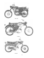
50 Sport, 60 Sport, 90, 90 Trail,
90 Mountain, 90 Sport, 175 Dual Twin
from Fourth Printing June, 1974
Originally Published by
CLYMER PUBLICATIONS
World's largest publisher of books devoted exclusively to
automobiles and motorcycles.
222 NORTH VIRGIL AVENUE, LOS ANGELES, CALIFORNIA 90004
TECHNICAL HANDBOOK
Index
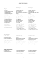
SPECIFICATIONS . . . . . . . . . . . . . . . . . . . . . . . . . . . . . . . . . . . . . . . . . . . 1
BS 50 Sport . . . . . . . . . . . . . . . . . . . . . . . . . . . . . . . . . . . . . . . . . . . . . . . . 1
BS 60 Sport . . . . . . . . . . . . . . . . . . . . . . . . . . . . . . . . . . . . . . . . . . . . . . . . 1
90 cc . . . . . . . . . . . . . . . . . . . . . . . . . . . . . . . . . . . . . . . . . . . . . . . . . . . . . . 3
175 Dual Twin . . . . . . . . . . . . . . . . . . . . . . . . . . . . . . . . . . . . . . . . . . . . . 5
I. ENGINE DISASSEMBLY & REASSEMBLY . . . . . . . . . . . . . . . . . . 7
50 Sport, 60 Sport and 90cc models . . . . . . . . . . . . . . . . . . . . . . . . . . . 7
II. REASSEMBLY . . . . . . . . . . . . . . . . . . . . . . . . . . . . . . . . . . . . . . . . 12
175 DT . . . . . . . . . . . . . . . . . . . . . . . . . . . . . . . . . . . . . . . . . . . . . . . . . . . 15
II. ENGINE DISASSEMBLY . . . . . . . . . . . . . . . . . . . . . . . . . . . . . . . 16
III. ENGINE REASSEMBLY . . . . . . . . . . . . . . . . . . . . . . . . . . . . . . 19
IV. INSTALLING ENGINE INTO FRAME . . . . . . . . . . . . . . . . . . 24
CYLINDERS AND PISTONS . . . . . . . . . . . . . . . . . . . . . . . . . . . . . . . . . 26
A. Construction and Operation: . . . . . . . . . . . . . . . . . . . . . . . . . . . . . 26
CRANKSHAFT AND ROTARY DISC VALVES . . . . . . . . . . . . . . . . 27
A. Construction and Operation . . . . . . . . . . . . . . . . . . . . . . . . . . . . . 27
B. Rotary Valve Modification . . . . . . . . . . . . . . . . . . . . . . . . . . . . . . . 28
50-60 SPORT, 90 & 90 SPORT . . . . . . . . . . . . . . . . . . . . . . . . . . . 28
175 DUAL TWIN . . . . . . . . . . . . . . . . . . . . . . . . . . . . . . . . . . . . . . . 29
KICK STARTER MECHANISM . . . . . . . . . . . . . . . . . . . . . . . . . . . . . . 29
Construction and Operation . . . . . . . . . . . . . . . . . . . . . . . . . . . . . . . . 29
CLUTCH . . . . . . . . . . . . . . . . . . . . . . . . . . . . . . . . . . . . . . . . . . . . . . . . . . . 31
A. Construction . . . . . . . . . . . . . . . . . . . . . . . . . . . . . . . . . . . . . . . . . . . 31
B. Operation . . . . . . . . . . . . . . . . . . . . . . . . . . . . . . . . . . . . . . . . . . . . . . 32
C. Adjustment . . . . . . . . . . . . . . . . . . . . . . . . . . . . . . . . . . . . . . . . . . . . 32
TRANSMISSION . . . . . . . . . . . . . . . . . . . . . . . . . . . . . . . . . . . . . . . . . . . . 34
A. Construction and Operation . . . . . . . . . . . . . . . . . . . . . . . . . . . . . 34
B. Gear Shift Mechanism . . . . . . . . . . . . . . . . . . . . . . . . . . . . . . . . . . . 35
C. Gear Shift Operation . . . . . . . . . . . . . . . . . . . . . . . . . . . . . . . . . . . . 37
D. Gear Ratios . . . . . . . . . . . . . . . . . . . . . . . . . . . . . . . . . . . . . . . . . . . . 41
CARBURETOR . . . . . . . . . . . . . . . . . . . . . . . . . . . . . . . . . . . . . . . . . . . . . 42
A. Construction and Operation . . . . . . . . . . . . . . . . . . . . . . . . . . . . . 42
B. Functions of Various Parts . . . . . . . . . . . . . . . . . . . . . . . . . . . . . . . 44
C. Adjustment . . . . . . . . . . . . . . . . . . . . . . . . . . . . . . . . . . . . . . . . . . . . 45
TO ADJUST FLOAT LEVEL: . . . . . . . . . . . . . . . . . . . . . . . . . . . . 46
OIL INJECTION SYSTEM – 90cc . . . . . . . . . . . . . . . . . . . . . . . . . . . . . 47
A. Construction and Operation . . . . . . . . . . . . . . . . . . . . . . . . . . . . . 47
B. Adjustment . . . . . . . . . . . . . . . . . . . . . . . . . . . . . . . . . . . . . . . . . . . . 48
C. Special Attention to the Oil Injection System . . . . . . . . . . . . . . 49
OIL INJECTION SYSTEM – 175DT . . . . . . . . . . . . . . . . . . . . . . . . . . 50
A. Construction and Operation . . . . . . . . . . . . . . . . . . . . . . . . . . . . . 50
B. Adjustment . . . . . . . . . . . . . . . . . . . . . . . . . . . . . . . . . . . . . . . . . . . . 51
C. Special Attention — Pump Modification . . . . . . . . . . . . . . . . . . . 52
ELECTRICAL EQUIPMENT – 50, 60 Sport, 90cc . . . . . . . . . . . 53
A. Ignition System . . . . . . . . . . . . . . . . . . . . . . . . . . . . . . . . . . . . . . . . 53
Contact Breaker . . . . . . . . . . . . . . . . . . . . . . . . . . . . . . . . . . . . . . . . 53
Ignition Timing . . . . . . . . . . . . . . . . . . . . . . . . . . . . . . . . . . . . . . . . . 53
TO SET TIMING . . . . . . . . . . . . . . . . . . . . . . . . . . . . . . . . . . . . . 53
Condenser . . . . . . . . . . . . . . . . . . . . . . . . . . . . . . . . . . . . . . . . . . . . . 54
Spark Plug . . . . . . . . . . . . . . . . . . . . . . . . . . . . . . . . . . . . . . . . . . . . . 54
B. Testing the Ignition Coil . . . . . . . . . . . . . . . . . . . . . . . . . . . . . . . . 55
C. Technical Standards . . . . . . . . . . . . . . . . . . . . . . . . . . . . . . . . . . . . 55
D. Lighting System . . . . . . . . . . . . . . . . . . . . . . . . . . . . . . . . . . . . . . . . 55
E. Testing the Lighting Coil . . . . . . . . . . . . . . . . . . . . . . . . . . . . . . . . 56
F. Selenium Rectifier . . . . . . . . . . . . . . . . . . . . . . . . . . . . . . . . . . . . . . 56
G. Battery Charging (50-60 Spt) . . . . . . . . . . . . . . . . . . . . . . . . . . . . 56
ELECTRICAL EQUIPMENT – 175 DT . . . . . . . . . . . . . . . . . . . . . . . 57
Contact Breakers . . . . . . . . . . . . . . . . . . . . . . . . . . . . . . . . . . . . . . . 57
Ignition timing . . . . . . . . . . . . . . . . . . . . . . . . . . . . . . . . . . . . . . . . . 57
TO CHECK TIMING - RIGHT CYLINDER . . . . . . . . . . . . . . . 57
RIGHT CYLINDER TIMING ADJUSTMENT . . . . . . . . . . . . . 58
TO CHECK TIMING-LEFT CYLINDER . . . . . . . . . . . . . . . . . . 58
LEFT CYLINDER TIMING ADJUSTMENT . . . . . . . . . . . . . . 58
B. Ignition Coils . . . . . . . . . . . . . . . . . . . . . . . . . . . . . . . . . . . . . . . . . . . 58
C. Technical Standards . . . . . . . . . . . . . . . . . . . . . . . . . . . . . . . . . . . . 59
D. Generator . . . . . . . . . . . . . . . . . . . . . . . . . . . . . . . . . . . . . . . . . . . . . . 59
E. Selenium Rectifier . . . . . . . . . . . . . . . . . . . . . . . . . . . . . . . . . . . . . . 60
F. Battery . . . . . . . . . . . . . . . . . . . . . . . . . . . . . . . . . . . . . . . . . . . . . . . . 60
G. Headlight . . . . . . . . . . . . . . . . . . . . . . . . . . . . . . . . . . . . . . . . . . . . . . 60
H. Spark plugs . . . . . . . . . . . . . . . . . . . . . . . . . . . . . . . . . . . . . . . . . . . . 60
Dry Charged Storage Batteries . . . . . . . . . . . . . . . . . . . . . . . . . . . . . . . 61
FRONT FORK . . . . . . . . . . . . . . . . . . . . . . . . . . . . . . . . . . . . . . . . . . . . . 63
Operation . . . . . . . . . . . . . . . . . . . . . . . . . . . . . . . . . . . . . . . . . . . . . . . . 63
Maintenance . . . . . . . . . . . . . . . . . . . . . . . . . . . . . . . . . . . . . . . . . . . . . . 63
Assembling Front Fork . . . . . . . . . . . . . . . . . . . . . . . . . . . . . . . . . . . . 63
REAR SUSPENSION . . . . . . . . . . . . . . . . . . . . . . . . . . . . . . . . . . . . . . . 64
FRONT WHEEL . . . . . . . . . . . . . . . . . . . . . . . . . . . . . . . . . . . . . . . . . . . 65
Removing Front Wheel . . . . . . . . . . . . . . . . . . . . . . . . . . . . . . . . . . . . 65
Adjusting Front Brake . . . . . . . . . . . . . . . . . . . . . . . . . . . . . . . . . . . . . 65
REAR WHEEL . . . . . . . . . . . . . . . . . . . . . . . . . . . . . . . . . . . . . . . . . . . . . . 66
Removing Rear Wheel . . . . . . . . . . . . . . . . . . . . . . . . . . . . . . . . . . . . . 66
Adjusting Rear Brake . . . . . . . . . . . . . . . . . . . . . . . . . . . . . . . . . . . . . 67
PRE-DELIVERY SERVICE . . . . . . . . . . . . . . . . . . . . . . . . . . . . . . . . . 68
B/S 90 w/Oil Injection . . . . . . . . . . . . . . . . . . . . . . . . . . . . . . . . . . . . . . 68
175 DT . . . . . . . . . . . . . . . . . . . . . . . . . . . . . . . . . . . . . . . . . . . . . . . . . . . 69
TROUBLESHOOTING: ENGINE . . . . . . . . . . . . . . . . . . . . . . . . . . . 71
I. PRELIMINARY CHECK . . . . . . . . . . . . . . . . . . . . . . . . . . . . . . . . 71
II. SPARK PLUG . . . . . . . . . . . . . . . . . . . . . . . . . . . . . . . . . . . . . . . . . 71
III. ENGINE OVERHEATING . . . . . . . . . . . . . . . . . . . . . . . . . . . . . 74
TROUBLESHOOTING: TRANSMISSION . . . . . . . . . . . . . . . . . . . 75
I. MISSED GEARS . . . . . . . . . . . . . . . . . . . . . . . . . . . . . . . . . . . . . . . . 75
TROUBLESHOOTING: ELECTRICAL . . . . . . . . . . . . . . . . . . . . . . 76
50, 60 Spt; 90cc . . . . . . . . . . . . . . . . . . . . . . . . . . . . . . . . . . . . . . . . . . . . 76
I. KEY SWITCH . . . . . . . . . . . . . . . . . . . . . . . . . . . . . . . . . . . . . . . . 76
II. CHARGING SYSTEM . . . . . . . . . . . . . . . . . . . . . . . . . . . . . . . . 76
III. BRAKE LIGHT SWITCH . . . . . . . . . . . . . . . . . . . . . . . . . . . . 76
IV. HEAD LIGHT . . . . . . . . . . . . . . . . . . . . . . . . . . . . . . . . . . . . . . . 77
V. HORN CIRCUIT . . . . . . . . . . . . . . . . . . . . . . . . . . . . . . . . . . . . . 77
VI. SELENIUM RECTIFIER . . . . . . . . . . . . . . . . . . . . . . . . . . . . 77
175 DT . . . . . . . . . . . . . . . . . . . . . . . . . . . . . . . . . . . . . . . . . . . . . . . . . . . 77
ALL MODELS . . . . . . . . . . . . . . . . . . . . . . . . . . . . . . . . . . . . . . . . . . . . 78
INSPECTION AND MAINTENANCE . . . . . . . . . . . . . . . . . . . . . . . 79
SERVICE STANDARDS . . . . . . . . . . . . . . . . . . . . . . . . . . . . . . . . . . . . 80
APPENDIX . . . . . . . . . . . . . . . . . . . . . . . . . . . . . . . . . . . . . . . . . . . . . . . . . 81
USEFUL FORMULAS AND TABLES . . . . . . . . . . . . . . . . . . . . . 81
CONVERSIONS . . . . . . . . . . . . . . . . . . . . . . . . . . . . . . . . . . . . . . . . 82
EXAMPLES OF CONVERSIONS . . . . . . . . . . . . . . . . . . . . . . . . 83
TEMPERATURE . . . . . . . . . . . . . . . . . . . . . . . . . . . . . . . . . . . . . . . 83
PISTON DISPLACEMENT . . . . . . . . . . . . . . . . . . . . . . . . . . . . . . 83
COMPRESSION RATIO . . . . . . . . . . . . . . . . . . . . . . . . . . . . . . . . 84
HORSEPOWER AND TORQUE . . . . . . . . . . . . . . . . . . . . . . . . . 85
PISTON SPEED . . . . . . . . . . . . . . . . . . . . . . . . . . . . . . . . . . . . . . . . 85
GEAR RATIO . . . . . . . . . . . . . . . . . . . . . . . . . . . . . . . . . . . . . . . . . . 86
BOLT TORQUE . . . . . . . . . . . . . . . . . . . . . . . . . . . . . . . . . . . . . . . . 87
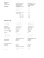
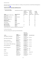
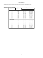
SPECIFICATIONS
BS 50 Sport
BS 60 Sport
2-stroke, Single Cyl.
50cc.(3.15cu.in.)
39 mm x 42 mm (1.53 x 1.65 in.)
6.60:1
5.2 HP/8500 rpm.
0.45 kg-m/7500 rpm.
2-stroke, Single Cyl.
58cc.(3.54cu.in.)
42 mm x 42 mm (1.65 x 1.65)
6.70:1
5.6 HP/8500 rpm.
0.48 kg-m/7500 rpm.
(7) Air Intake System:
(8) Starting System:
(9) Charging System:
(10) Ignition System:
(11) Ignition Timing:
Rotary Disc Valve
Kick Starter
A.C. Magneto
Flywheel Magneto
19° before T.D.C.
Rotary Disc Valve
Kick Starter
A.C. Magneto
Flywheel Magneto
19° before T.D.C.
(12) Spark Plug:
N.G.K. B-7
N.G.K.. B-8
(13) Carburetor:
(14) Fuel Mixture:
AMAL Type, VW15SC.
20 to 1 (gasoline)
(motor oil SAE No. 30)
0.132 gal. in trans.
case; SAE #20 (winter)
or SAE 10W30 (all season)
AMAL Type, VW15SC.
20 to 1 (gasoline)
(motor oil SAE No. 30)
0.132 gal. in trans.
case; SAE #20 (winter)
or SAE 10W30 (all season)
'Engine:
(1) Type:
(2) Piston Displacement:
(3) Bore & Stroke
(4) Compression Ratio:
(5) Max. Brake H.P.
(6) Max. Torque:
(15) Transmission Oil:
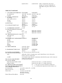
* Performance:
(1) Max. Speed:
85 km/h (53 mph)
88 km/h (55 mph)
(2) Climbing Ability:
(3) Fuel Consumption:
1 in 3.5
200mpg/20mph at 30km/h
paved level test road
1 in 3.5
176mpg/20mph at 30km/h
paved level test road
(4) Min. Turning Radius:
(5) Acceleration:
1.8m (70.8 inch)
14.5 sec. (Stan. st. 0-200 m)
1.8m (70.8 inch)
14.0 sec. (Stan. st. 0-200 m)
(6) Braking Distance:
Less than 8 m at 35 km/h
(26 feet, at 22 mph)
Less than 8 m at 35 km/h
(26 feet, at 22 mph)
'Frame & Suspension:
(1) Frame Type:
(2) Front Suspension:
Pressed Steel/Backbone
Telescopic Fork with
Hydraulic Damper
1
Pressed Steel/Backbone
Telescopic Fork with
Hydraulic Damper,
'Transmission
(1) Clutch:
Manual, Multi. disc in oil
Manual, Multi. disc in oil
(2) Transmission:
4 speed constant mesh
4 speed constant mesh
gear & foot control
gear & foot control
(3) Gear Ratio:
Primary (Hel. gr.) 1 : 4.05
1 : 4.05
Gear Box: 1st: 1 : 2.92
1 : 2.92
2nd: 1 : 1.83
1 : 1.83
3rd: 1:1.32
1 : 1.32
4th: 1 : 1.00
1 : 1.00
Secondary (Chain): 1 : 2.77
1 : 2.54
Total Gear Ratio:
1st: 1 : 32.8
1 : 30.0
2nd: 1 : 20.5
1 : 18.8
3rd: 1 : 14.8
1 : 13.6
4th: 1 : 11.2
1 : 10.3
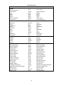
•Dimensions, Weight:
(1) Overall Length:
1,810 mm (71.3 in.)
1,810 mm (71.3 in.)
(2) Overall Width:
660 mm (26.0 in.)
660 mm (26.0 in.)
(3) Overall Height:
970 mm (38.1 in.)
970 mm (38.1 in.)
(4) Saddle Height:
750 mm (29.5 in.)
750 mm (29.5 in.)
(5) Wheelbase:
1,160 mm (45.7 in.)
1,160 mm (45.7 in.)
(6) Road Clearance:
130 mm (5.10 in.)
130 mm (5.10 in.)
(7) Tire Size (Front):
2.25-17, 4 ply
2.25-17, 4 ply
(Rear):
2.25-17, 4 ply
2.25-17, 4 ply
22.8 lbs/in2
22.8 lbs/in2
28.4 lbs/in2
28.4 lbs/in2
(9) Caster:
63
63
(10) Trail:
78 mm (3.07 inch)
78 mm (3.07 inch)
(11) Banking Angle:
45 degrees
45 degrees
(12) Net Weight:
69 kg (152 lbs)
69 kg (152 lbs)
(13) Fuel Tank Capacity:
1.72 gal.
1.72 gal.
including 0.264 gal. reserve
including 0.264 gal. reserve
(14) Front Brake:
Right Hand
Right Hand
(15) Rear Brake:
Right Foot
Right Foot
(1) Head light:
6V-15/15W
6V-15/15W
(2) Tail light:
6V-2W
6V-2W
6V-5W (exclusively C.H.P.)
6V-5W
6V-18W (exclusively C.H.P.)
6V-18W
(3) Stop light:
6V-8W
6V-8W
(4) Battery:
6V-2AH
6V-2AH
(8) Tire Pressure (Front):
(Rear):
'Electrical Equipment:
2
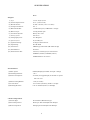
SPECIFICATIONS
90 cc
*Engine:
(1) Type:
2-stroke. Single Cylinder
(2) Piston Displacement:
88 c.c. (5.39 cu-inch)
(3) Bore & Stroke:
50 mm x 45 mm (1.97 x 1.77 inch)
(4) Compression Ratio:
6.8 : 1
(5) Max. Brake H.P.
7.8 HP/7000 rpm. (8.8 HP/8000 - 90 Spt)
(6) Max. Torque:
0.85 kg-m/5000 rpm
(7) Air Intake System:
Rotary disc valve
(8) Starting System:
Kick Starter
(9) Charging System:
A.C. Magneto
(10) Ignition System:
Flywheel Magneto
(11) Ignition Timing:
21 degrees before T.D.C.
(12) Spark Plug:
N.G.K. B-7H
(13) Carburetor:
AMAL Type, VM 15SC (VM 17SC-90 Spt)
(14) Fuel Mixture:
Gasoline
(15) Transmission Oil:
0.6 litre (0.158 US gal.) in transmission
SAE #30 (summer); SAE #20 (winter)
SAE #10W30 in all seasons
*Performance:
(1) Max. Speed:
95km/h(60mph) (105 kh/h—65 mph—90 Spt)
(2) Climbing Gradient:
1 in 3
(3) Fuel Consumption:
75 km/L (177 mpg/20 mph) at 30 km/h on paved
flat test road
(4) Min. Turning Radius:
1.8 m (70.8 inch)
(5) Acceleration:
13.0 seconds (0-200 m) (12.0Sec—90 Spt)
(6) Braking Distance:
6 m at 35 km/h (20 feet, at 22 mph)
* Frame Suspension:
(1) Frame Type:
Pressed Steel, Backbone Type
(2) Front Suspension:
Telescopic Fork with Hydraulic Damper
(3) Rear Suspension:
Swinging Arm with Hydraulic Damper
3
•Transmission
(1) Clutch:
Manual, Multiple discs in oil bath
(2) Transmission:
4 speed constant-mesh gear & foot control
(3) Gear Ratio:
Primary (Helical Gear):
1 : 3.95
1st: 1: 2.77
2nd: 1: 1.72
3rd: 1: 1.23
4th: 1: 0.924
Secondary (Chain):
1 : 2.43
Total Gear Ratio:
1st:
1 : 26.58
2nd: 1: 16.51
3rd: 1: 11.81
4th: 1: 8.86
'Dimensions & Weight:
(1) Overall Length:
1,830 mm (72.0 inch)
(2) Overall Width:
with Standard Handle Bar 660 mm (26.0 inch)
with Flat Bar
580 mm (22.8 inch)
(3) Overall Height:
970 mm (38.1 inch)
(4) Saddle Height:
750 mm (29.5 inch) (30.1 inch—90 Spt)
(5)Wheel base:
1,160 mm (45.7 inch)
(6) Road Clearance:
150 mm (5.9 inch)
(7) Tire Size (Front):
2.50-17, 4 ply
(Rear):
2.50-17, 4 ply
(8) Tire Pressure:
(Front):
1.6kg/cm(22.8 lbs/in)
(Same—90 Spt)
(Rear):
2.4 kg/cm (34.2 lbs/in)
(28.4 Ibs/in—90 Spt)
(9) Caster:
63 degrees
(10) Trail:
80 mm (3.15 inch)
(11) Banking Angle:
45 degrees (47 degrees – 90 Spt)
(12) Net Weight:
79kg(1741bs)
(13) Fuel Tank Capacity:
7.0 L (1.85 US gal) (2.25 US gal—90 Spt)
including 0.264 gal. reserve (0.396 gal—90 Spt)
(14) Front Brake:
Right Hand
(15) Rear Brake:
Right Foot
*Electrical Equipment:
(1) Head light:
6V-15/15W
(2) Tail light:
6V-2W
(3) Stop light:
6V-8W
(4) Turn signal light:
6V-8W
(5) Battery:
6V-4AH
4
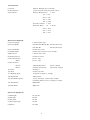
SPECIFICATIONS
175 Dual Twin
*Engine
(1) Type :
2-stroke, Dual Cylinders
(2)
Piston Displacement:
177 cc. (10.8 cu-inch)
(3)
Bore & Stroke:
50 mm × 45 mm (1.97 × 1.77 inch)
(4)
Compression Ratio:
9.5: 1
(5)
Max. Brake Horsepower:
20HP/8,000 rpm
(6)
Max. Torque :
1.9 kg-m/7, 500 rpm
(7)
Air Intake System :
Rotary disc valve
(8)
Starting System :
Kick Starter
(9)
Charging System :
A. C. Generator
(10) Ignition System :
Battery
(11) Ignition Timing:
(21 +1,-2) degrees before T.D.C.
(12) Spark Plugs :
N G K B-8 H
(13) Carburetors :
AMAL Type. VM 17 SC
(14) Engine Lubrication :
2 cycle engine motor oil
(15) Fuel:
Gasoline
(16) Transmission oil :
0.8 litre (0.21 US gal.) in transmission case
SAE No. 10W/30 in all seasons or
SAE No. 30 in summer and SAE No. 20 in winter
*Performance
(1) Max. Speed:
Over 130km/h(80 mph)
(2) Climbing Gradient:
1 in 3
(3) Fuel Consumption:
55 km/l (129 mpg) at 40 km/h (25 mph) on paved flat test road.
(4) Min. Turning Radius :
1.95 m (76. 8 inch)
(5) Acceleration:
(Standing Start 1/4 mile)
(6) Braking Distance :
Under 18 sec (0-400 m)
Less than 6 m at 35 km/h (20 feet, at 22 mph).
*Frame & Suspension
(1) Frame Type :
Pipe Frame, Cradle Type
(2) Front Suspension :
Telescopic Fork with Hydraulic Damper
(3) Rear Suspension :
Swinging Arm with Hydraulic Damper
5
*Transmission
( 1 ) Clutch :
Manual, Multiple discs in oil bath.
( 2 ) Transmission :
Dual Transmission, selective 4-speed constant mesh-rotary or
5-speed constant mesh-return by shifting "sportshift" lever
( 3 ) Gear Ratios:
Primary (Helical gear) :
Gear Box:
1:3.41
1st
2nd
3rd
1:1.67
1:1.24
4th
5th
1:1.00
1: 0.85
Secondary (Chain):
Total Gear Ratio :
1st
2nd
3rd
1:13.50
1:10.03
4th
5th
1: 8.10
1:6.86
1:2.61
1: 2.37
1:21.19
*Dimensions and Weight
(1 ) Overall Length:
( 2 ) Overall Width :
1,885 mm (74.2 inch)
750 mm (29.5 inch)
( 3 ) Overall Height:
with Standard Western type Handlebar
1,020 mm (40.2 inch)
( 4 ) Saddle Height :
( 5 ) Wheelbase:
780 mm (30.7 inch)
1,235mm (48. 6 inch)
( 6 ) Road Clearance :
( 7 ) Tire Size
(Front):
150 mm ( 5.9 inch)
2.50-18 4 ply
(8) Tire Pressure
(Rear) :
(Front):
2.75-18 4 ply
1.6kg/cm2 (221bs/in2)
(Rear) :
( 9 ) Caster :
2.0 kg/cm2 (23 lbs/in2)
64°
(10) Trail :
(11) Banking Angle :
83.5 mm (3.29 inch)
45°
(12) Net Weight :
(13) Fuel Tank Capacity:
123 kg (271 lbs)
10 L (2.64 US gal.)
(14) Oil Tank Capacity :
Including 1.2 litre (0.317 US gal.) reserve
1.8 L (3.8 pint)
(15) Front Brake :
(16) Rear Brake :
Right Hand Operated
Right Foot Operated
*Electrical Equipment
( 1 ) Head light :
( 2 ) Tail light:
12 V - 35/25 W
12V-8W
( 3 ) Stop light:
( 4 ) Speedometer lamp:
12V-25W
12V-3W
( 5 ) Third gear indicator lamp:
( 6 ) Neutral indicator lamp:
12V-2W
12V-2W
( 7 ) Battery:
12V-6AH
6
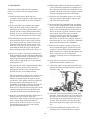
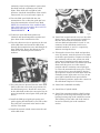
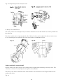
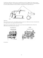
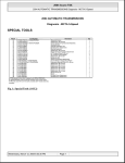
I. ENGINE DISASSEMBLY & REASSEMBLY
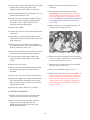
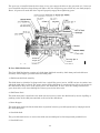
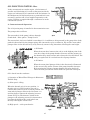
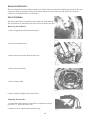
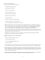
6. Insert a screw driver through the access
aperture and loosen the carburetor mounting
bolt. (Fig. 2)
50 Sport, 60 Sport and 90cc models
7. Disconnect the fuel line from the fuel cock.
Most service can be performed on the engine
without removing the engine from the frame. In
fact, all operations which occur before the actual
splitting of the crankcase sections can be
accomplished with the engine mounted in the
cycle frame. For complete engine disassembly, it
is necessary to remove the engine from the frame.
This sequence describes the dismounting of the
engine from the frame, the complete disassembly
of the engine, and engine reassembly.
8. Remove the carburetor from the carburetor
adapter and allow it to hang suspended from
the throttle cable and starter jet cable.
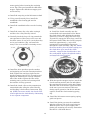
9. Remove the clutch release arm lock nut and
washer and remove the clutch release arm
from the release screw. (Fig. 3)
10. Disconnect the clutch cable from the clutch
release arm.
1. Remove the drain plug from the under side of
the transmission case and completely drain
the crankcase. Replace the drain plug.
2. Turn the fuel cock selector lever to the "O"
position to shut off the fuel between the tank
and the carburetor.
3. Raise the rubber carburetor cap.
4. Remove the carburetor cover from the side of
the transmission case by removing the phillips
head attaching screws.
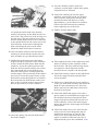
11. Unscrew the clutch cable adjusting screw
completely out of the threaded boss on top of
the carburetor enclosure.
12. Pull the clutch cable free of the carburetor
enclosure.
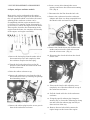
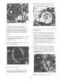
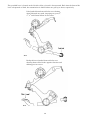
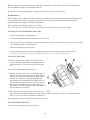
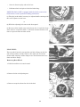
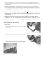
13. Using the special exhaust pipe clamp nut
wrench, (Fig. 4) loosen the exhaust pipe clamp
nut and rotate the exhaust pipe toward you
down and out of the way.
5. Remove the rubber plug from the access port in
front of the carburetor enclosure.
14. Remove the two bolts which connect the
engine hanger to the front of the engine.
7
Loosen the bolt at the top of the engine hanger
and swing the engine hanger forward.
15. Moving to the left hand side of the machine,
remove the gear shift lever.
16. Remove the magneto cover retaining screws.
17. Remove the two hex head bolts from the lower
half of the chain case and remove the lower
chain case section.
18. Remove the left hand battery cover.
Disconnect the wires running from the
magneto to the battery. Remove the battery
band and remove the battery. Locate the chain
connecting link and chain connector.
Dismount the drive chain from the small
sprocket. Temporarily reconnect the chain to
avoid losing the chain connector. Pull the
magneto wire loom out of the cycle frame.
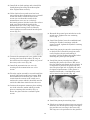
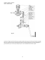
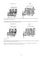
24. As soon as the cylinder is removed, insert the
piston seat (special tool) under the piston. This
special tool protects the piston during
disassembly and it also holds the crankshaft
stationary for further disassembly operation.
(Fig. 5)
25. Remove the piston pin snap rings and remove
the piston pin and piston from the connecting
rod. A suitable piston pin puller must be used
in this operation. This is provided in the
Bridgestone special tool kit.
19. Remove the nuts from the engine mounting
bolts. The nuts are located on the right hand
side of the machine. Withdraw the engine
mounting bolts from the left hand side of the
machine.
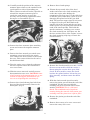
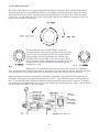
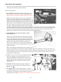
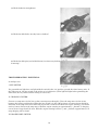
26. Position the engine on the bench, magneto
side up. Hold the magneto stationary with the
stopper wrench (special tool) and, using a
socket wrench, remove the magneto retaining
nut and lock washer. (Fig. 6)
20. Lower the engine out of the frame.
27. Mount the magneto puller (special tool) and
holding the magneto stationary with the
stopper wrench, remove the fly wheel
magneto. CAUTION: When mounting the
magneto puller on the 90cc fly wheel magneto,
insert the three attaching screws just far
enough to engage two or three threads. If
these screws are turned in too far, it is possible
to damage the magneto coils.
21. Place the engine on the bench and remove the
kick starter lever.
22. Remove the cylinder head mounting bolts
using a 10mm socket wrench.
23. Using a 10mm open end wrench, remove the
four cylinder mounting nuts. Lift the cylinder
off the cylinder mounting studs.
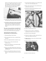
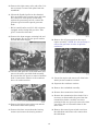
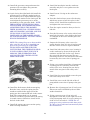
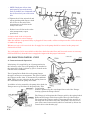
28. Remove the wire from the neutral gear
switch. (Fig. 7)
8
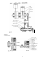
29. Carefully mark the position of the magneto
armature plate relative to the crankcase with
a prick punch or with a felt marking pen.
These reference marks will make it possible to
reinstall the magneto armature plate in
exactly the same position to avoid the
necessity of major timing adjustments when
the engine is reassembled. (Fig. 8)
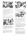
35. Remove the 6 clutch springs.
36. Flatten the up turned sides of the bend
washer and remove the clutch retaining nut
on the 90cc engine after shifting the
transmission into first gear. Use the shift lever
to shift the gears rather than a pliers to avoid
damaging the splined end of the gear shift
shaft. The sprocket stopper (special tool) must
be slipped over the gear shift shaft on the
opposite side of the engine and the steel pegs
on this special tool are positioned between the
teeth of the small sprocket. This holds the
sprocket stationary, enabling you to remove
the clutch retaining nut. (See figure 10). On
the 50cc and 60cc rotary valve engines, remove
the clutch retaining snap ring to remove the
clutch assembly.
30. Remove the three armature plate attaching
screws and remove the magneto armature
plate.
31. Remove the three neutral gear switch cover
mountings screws and remove the switch
cover. Remove the brass contact located under
the cover. This contact is fitted to the end of
the shift drum shaft.
32. Turn the engine over so that the carburetor
side faces up and remove the transmission
case cover screws.
37. Remove the clutch assembly as a unit. NOTE:
On more recent models of the 90cc series, a
thrust spring fits over the drive gear of the
clutch. In these models, remove the clutch
bracket, the splined washer, lift out the gear
drive assembly, and then remove the thrust
spring.
33. With the screws removed, carefully remove
the transmission case cover. CAUTION: Some
oil will remain in the transmission case so use
caution in removing the transmission case
cover to avoid spilling this remaining oil.
38. With the clutch wrench (special wrench),
remove the pinion gear nut from the end of the
crankshaft. (On the newer models this
retaining nut can be removed with a socket
wrench.) CAUTION: This is a left hand
thread. The crankshaft can be kept from
rotating during the removal of the pinion gear
retaining nut if the piston seat is put in place.
34. Remove the 6 clutch thrust plate bolts from
the top of the clutch assembly. Remove the
thrust plate. (Fig. 9)
39. Remove the pinion gear from the end of the
crankshaft.
40. Remove the 6 rotary valve cover screws and
remove the rotary valve cover.
9
41. To remove the rotary valve disc, insert your
finger up through the bottom of the fuel inlet
port and gently dislodge the rotary valve disc
from the crankshaft collar. If a screw driver is
used to assist in removing the disc, use
extreme caution to avoid damaging any part of
the rotary valve cavity. (Fig. 11)
48. Lift the shift arm pawl free of the shift
drum and holding it in this position, carefully
withdraw the shift arm and shaft assembly.
Inspect the shift arm assembly for bends,
damage or abnormal wear. Remove the thrust
receiver.
42. Remove the crankshaft collar and locating
pin. The locating pin may be removed with a
needle-nosed pliers.
49. Position the engine on the bench with the
magneto side facing upwards and remove the
crankcase retaining screws. It may be
necessary to use an impact driver to remove
these screws as they are inserted very tightly.
The impact driver will enable you to remove
the screws without damaging the screw heads.
See tool list, figure 1. (The drive sprocket
should be removed as soon as the engine is
turned magneto side up.)
43. Remove the washer and spring guide from the
kick starter shaft.
44. Unhook the upper spring hook on the kick
starter return spring by striking the upper
end of the spring on the side opposite the
spring hook. This will pop the spring hook
from the hole in the kick starter shaft.
50. With all crankcase retaining screws removed,
carefully tap the crankcase with a soft faced
hammer to break the gasket seal and separate
the crankcase halves.
45. Unhook the lower end of the kick starter
return spring from the crankcase and lift off
the spring.
46. Using the circlip expander (special tool)
remove the circlip from the kick starter shaft.
51. Carefully lift out the two transmission shafts
and gears together with the shift drum-shift
fork assembly.
47. Using an open end wrench, remove the shift
drum stopper pivot screw (Fig. 12). Unhook
the shift drum stopper spring and remove the
shift drum stopper. Inspect it for bends of
abnormal wear. The disc on the end of the
shift drum stopper should rotate freely.
52. Remove the shift drum/shift fork assembly
from the transmission gears and inspect the
shift forks for bends or abnormal wear. (Fig.
13)
10
53. Inspect the two transmission shafts and gears
to be certain that they are all in good
condition. Further disassembly of the
transmission is not necessary unless one or
more of the gears must be replaced. If this is
necessary, carefully note the position of the
gears on the shaft before removing them for
replacement. (Fig. 14)
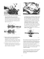
56. Withdraw the crankshaft assembly. Notice
that spacing shims are used on either side of
the crankshaft balance assembly. (Fig. 16) If
the same crankshaft is to be replaced, keep
these spacers on the crankshaft so that the
crankshaft end play will not be affected. The
number and thickness of spacers on this
crankshaft varies from engine to engine.
Occasionally the spacing shims will stick to
the crankshaft bearings. Inspect the bearings
carefully to be certain that these shims have
been removed from both the crankcase
sections if the oil present has caused them to
adhere to the bearings.
54. Remove the kick starter intermediate gear
which remains in the crankcase half after the
transmission shaft assembly has been
withdrawn. Note that there is a spacer above
and below this gear. Keep these spacers with
this gear to facilitate reinstallation. (Fig. 15)
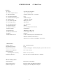
This completes the disassembly operation. Wash
all parts (except magneto armature plate) in a
cleaning solvent and inspect all bearings and oil
seals. If it is necessary to replace bearings, the
crankcase must be heated with a small torch in
the vicinity of the bearings to expand it
sufficiently to allow the bearing to be removed
and replaced. When using a torch, keep the torch
constantly in motion to avoid melting the
crankcase castings.
55. Withdraw the kick starter shaft and gear
assembly. Notice that there is a spacer on the
end of this shaft. Keep the spacer with this
shaft to facilitate reassembly.
If oil seals are to be replaced, coat them liberally
with oil and tap them into place with a small
hammer. Before beginning the reassembly
operation, oil all bearings and oil seals
thoroughly.
11
II. REASSEMBLY
6. Holding both shafts and shift drum together as
a unit, install the transmission assembly into
the crankcase half. When the shafts have been
partially inserted, rotate them slightly to mesh
all gears and properly position the shafts.
All parts installed inside the two crankcase
halves are installed into the magneto clutch
section.
1. Install the kick starter shaft and gear
assembly. Position the pin on the ratchet arm
into the boss provided for it in the crankcase
half.
7. Install the two remaining spacers, one on the
end of the countershaft and the other on the
end of the kick starter shaft.
8. Be certain that the crankshaft end play shims
are positioned on both sides of the crankshaft
balance and install the crankshaft. See figure
16. If a new crankshaft has been installed, it
will be necessary to put the crankcase gasket
into position, install the other crankcase
section and insert several of the crankcase
retaining screws tightly. The crankshaft
should now be checked for end play. If there is
more than .010" to .015" of end play, additional
shims must be added to the crankshaft.
2. Oil the kick idler gear assembly thoroughly.
This gear need not be removed from the
transmission case during disassembly as it is
pressed into the counter shaft (clutch shaft)
bearing. It is very unlikely that this gear will
ever be replaced during the life of the engine.
3. Reinstall the kick starter intermediate gear
positioning the spacers above and below the
gear. These spacers are identical and can be
identified since the hole in the spacer is the
same size as the hole in the gear. Place it in
mesh with the kick idler gear and the kick
starter shaft gear and oil the gears. (Fig. 15)
9. Install a new crankcase gasket locating it on
the steel positioning pins. Install the second
crankcase section. Again check transmission
shaft rotation to be certain that the shafts turn
freely. If found to be ok., reinstall the
crankcase retaining screws and tighten them
securely.
4. We are now ready to install the transmission
shaft assemblies and the shift drum/shift fork
assembly. Before doing so, familiarize yourself
with the positions into which the various
shafts and the shift drum will be inserted by
studying figure 15.
10. Trim the excess portion of the crankcase
gasket flush with the cylinder seat.
• The splined end of the countershaft (the shaft
with the smaller gears) will be inserted
through the kick idler gear, the gear that is
pressed into the countershaft bearing.
11. Install the spacer on the shift arm shaft and
position the shift arm shaft assembly into the
crankcase. (Fig. 17)
• The end of the drive shaft will be inserted into
the kick starter intermediate gear, the one
which was installed with the spacers above
and below it. The splined end of the shaft will
point up and the small sprocket will be
attached to it when the crankcase sections are
joined. The large diameter end of the shift
drum will be inserted into the large hole in the
casting located directly above the kick idler
gear and the kick starter intermediate gear.
12. Insert the shift arm pawl into the shift drum
assembly. Install the thrust receiver and bend
the tabs on the tab washer against the flats of
the bolts when the mounting bolts have been
secured. This tab washer prevents the bolts
from loosening during engine operation. (Fig.
12.)
5. Align the countershaft and drive shaft gears so
that all gears are in mesh. Plan your
installation of the shafts so that the longer end
of the countershaft extends through the
bottom of the crankcase section. Now insert
the shift forks into the slots of the sliding
gears of the transmission.
13. Install the shift drum stopper, collar and
retaining screw. Connect the drum stopper
12
return spring before inserting the retaining
screw. The collar goes beneath the shift drum
stopper. Tighten the shift drum stopper pivot
screw securely.
14. Install the snap ring on the kick starter shaft.
15. Using a needle-nosed pliers, install the
crankshaft collar locating pin into the
crankshaft.
16. Install the crankshaft collar over the locating
pin.
17. Install the rotary disc valve after coating it
and the valve cavity liberally with oil.
21. Install the clutch assembly onto the
countershaft and countershaft collar. Rotate
the clutch slowly while holding the sprocket
stationary in order to engage the drive dogs.
To positively engage the drive dogs, rotate the
kick starter shaft. When the clutch is properly
installed, approximately ½ inch of the
transmission countershaft will protrude
through the clutch assembly. (Fig. 20) NOTE:
On newer models, place the thrust spring over
the clutch drive gear, install the clutch
assembly, except for the clutch bracket, onto
the countershaft, replace the splined washer,
and install the clutch bracket.
18. Carefully check the large "O" ring around the
outer perimeter of the rotary valve cover and
check the center oil seal to be certain that they
are in good condition. (Fig. 18) Install the
rotary valve cover and the 6 retaining screws.
19. Install the drive sprocket, sprocket washer
and retaining nut onto the transmission drive
shaft. Tighten the nut finger tight. Put the
sprocket stopper (special tool) in position and
tighten the retaining nut securely. Bend the
tabs of the washer against the flats of the
retaining nut to prevent its loosening while
the machine is being operated.
22. With the sprocket stopper in place, install the
clutch retaining washer and nut and tighten
the retaining nut securely on the 90cc engine.
Bend the tabs of the washer against the flats
of the nut to prevent rotation of this nut
during engine operation. On the 50 and 60cc
engines, install the clutch retaining spring
clip.
20. Install the clutch collar on the transmission
countershaft after oiling the collar liberally
and checking it for freedom of movement. (Fig.
19) NOTE: On newer models, the clutch collar
is built right into the shaft thereby eliminating
it as a separate component.
23. Install the kick starter return spring, spring
guide and spacer.
24. Install the pinion gear onto the crankshaft
with the undercut side of the gear facing up.
With the piston seat in place, tighten the
pinion gear retaining nut securely. Remember
that this is a left hand thread.
13
25. Install the 6 clutch springs and reinstall the
clutch thrust plate using the 6 thrust plate
bolts. Tighten them securely.
26. If the clutch release push screw has been
removed from the transmission cover, reinstall
it from the inside so that the flats of the
screws (as seen from the outside of the
transmission cover) are in a relatively
horizontal position with the back of the release
push screw flush with the inside of the
transmission case cover. (Fig. 3) Be certain
that the thrust bearing has been liberally
coated with grease and inserted into the push
screw. (Fig. 21)
31. Reattach the neutral gear switch wire to the
switch cover. Tighten the wire retaining
screw. (Fig. 7)
32. Install the flywheel onto the crankshaft and,
holding the flywheel stationary with the
stopper wrench, tighten the flywheel retaining
nut securely.
33. Install the piston pin onto the connecting rod
to check for fit. It should be snug but rotate
easily. Replace the pin and bushing if
necessary. Oil the bushing thoroughly before
installing the piston pin and piston.
27. Position the transmission cover gasket on the
locating pins. Install the rubber "O" ring on
the carburetor inlet adapter, which is a part of
the rotary valve cover. (Fig. 22)
34. Install the piston pin and piston. When
installing the piston, the letters "EX" are to
face the exhaust port (front) on the cylinder. It
is important to position the piston this way
since the piston pin hole is slightly off center
for improved performance. If the piston is
installed backwards, a loud knocking sound
will be heard at low speeds. (Fig. 23)
28. Install the transmission case cover by
securing all the transmission case cover
screws.
29. Turn the engine assembly over and install the
neutral light switch gasket and contact. With
the transmission in neutral gear, check to be
certain that the contact in the switch cover
touches the contact which is installed onto the
end of the shift drum shaft. Secure the cover.
30. Position the magneto armature plate making
use of the reference marks which you made
prior to removing this assembly. (Fig. 8)
Secure the plate with the 3 armature plate
screws.
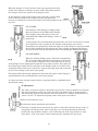
35. Install the piston pin retaining clips.
36. Check to see that the piston rings are properly
installed. The chrome plated ring is the upper
ring and the cast iron ring is the lower ring.
The rings are to be positioned on the piston so
14
that the locating pin on the piston is located in
the ring gap. (Fig. 24) The notch in the ring
gap should face up. If the notch faces down,
the rings cannot be compressed enough to
permit installation of the cylinder.
7. Loosen the clutch adjusting screw lock nut and
remove the clutch adjusting screw.
8. Remove the clutch release arm and disconnect
it from the clutch cable.
9. Unscrew the clutch cable adjusting screw all
the way out of the engine.
37. Install the cylinder onto the mounting studs
and install the lockwashers and nuts securely.
38. Install the cylinder head gasket and cylinder
head. Four flat washers are used under the
cylinder head nuts. Tighten the head nuts
progressively and evenly to 125 inch lbs. of
torque.
The engine is now completely reassembled and
ready for remounting in the cycle frame. The
engine mounting procedure is to be done in the
reverse order of the dismounting procedure.
10. Remove the kick starter lever.
11. Remove the cover plate on which the
transmission selector lever is mounted.
BRIDGESTONE 175 DT ENGINE
DISASSEMBLY AND REASSEMBLY
12. Remove the gear shift pedal.
13. Raise the carburetor rubber cap from the top
of the left carburetor enclosure.
I. Removing Engine From Frame
1. Drain transmission oil into a suitably large
container.
14. Remove the air cleaner duct from the rubber
carburetor cap.
2. Raise the right hand rubber carburetor cap.
15. Remove the left carburetor cover.
3. Remove the air cleaner duct from the
carburetor cap.
4. Remove the carburetor cover from the right
hand side of the engine.
5. Remove the rubber plug from the front of the
carburetor enclosure and loosen the carburetor
retaining bolt.
6. Remove the right hand carburetor. It can be
allowed to hang suspended from the throttle
cable.
16. Remove the left carburetor.
15
17. Remove the control cable from the oil injection
pump control arm by prying the cable
attaching bracket open with a screw driver.
3. Remove the connecting rod needle roller
bearings.
4. Remove the oil lines from the oil pump.
CAUTION: If the union bolts are removed
from the banjo connectors use care to avoid
losing the ball check valves from the union
bolts. NOTE: The earliest BS175 models were
not equipped with ball check valves in the
union bolts.
18. Remove the throttle cable adjusting screw out
from the transmission cover.
19. Remove the main oil pump supply line from
the fitting on the oil pump and plug this oil
line with a screw to prevent the oil from
draining out of the supply tank.
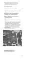
5. Remove the two screws which mount the oil
pump to the oil pump gear box.
20. Remove the saddle.
21. Remove the side cover from the left hand side
of the cycle.
22. Disconnect the wiring running between the
AC generator and the battery. These wires are
snap connected.
23. Disconnect the wires from the terminals on
the selenium rectifier. The wiring harness can
then be pulled free of the cycle.
24. Disconnect the master link on the drive chain
and remove the chain from both sprockets.
25. Disconnect the exhaust pipe clamps and
swing the exhaust pipes down, clear of the
engine.
6. Remove the four oil pump gear box mounting
screws. It will be necessary to rotate the pump
to remove the last two screws.
26. Remove the air cleaner.
7. Remove the oil pump and gear box assembly
from the rotary valve cover.
27. Remove the four engine mounting bolts from
the mounting plates at the front of frame
assembly.
8. Remove the left hand crank case cover.
9. Remove the rotary valve cover. CAUTION: If
it is necessary to pry this cover to remove it
from the crankcase, use extreme caution. Pry
only in the area immediately adjacent to
rotary valve cover locating pin. Prying may
cause damage to the crankcase which will
result in leaks.
28. Remove the lower rear engine mounting bolt.
29. Remove the upper rear engine mounting bolt.
This bolt should be withdrawn with a pliers
since all of the engine weight is now bearing
against this last bolt.
30. Remove the engine from the cycle frame.
II. ENGINE DISASSEMBLY
1. With the engine placed on a suitable bench,
remove the cylinder heads and cylinders.
2. Remove the piston pin retaining clips and,
using the piston pin pusher from the
Bridgestone Special Tool Kit, remove the
piston pins and pistons.
16
15. Place the clutch stopper, a special tool, in
place to hold the clutch stationary while the
clutch retaining nut is removed.
10. Remove the rotary valve from the
crankshaft. Removal can be facilitated by
inserting your index finger through the fuel
intake port from inside the crankcase and
pushing the valve off the crankshaft spline. It
is not necessary to remove the crankshaft
spline.
16. Loosen, but do not remove, the generator gear
mounting bolt.
17. Remove the clutch as a unit, by placing the
fingers of both hands around the clutch gear
while holding the center of the clutch in
position with your thumbs. (On more recent
models of the 173 DT, a thrust spring fits over
the drive gear of the clutch. On these models,
remove the retaining nut, the clutch hub, the
splined washer, the remaining clutch
assembly, and then the thrust spring, in that
order.)
11. Turn the engine around so that you can work
on its right hand side. Remove the
transmission cover mounting screws and the
transmission cover.
12. Remove the clutch thrust plate by removing
the six mounting bolts.
18. Insert the aluminum piston seat under the
upper end of one connecting rod to hold the
crankshaft stationary and loosen the pinion
gear retaining nut. THIS IS A LEFT HAND
THREAD. Remove the retaining nut and the
gear from the shaft.
13. Remove the clutch springs.
14. Place the transmission in any gear. With a
small chisel and hammer, flatten the bend
washer beneath the clutch retaining nut.
19. Remove the right rotary valve cover.
17
20. Remove the right rotary valve and collar. It is
not necessary to remove the spline from the
crankshaft.
21. Mount the flywheel puller in the threaded
holes provided in the generator gear and with
the center bolt of the special tool bearing
against the generator gear bolt, remove the
generator gear from the tapered generator
shaft.
• B/S 173 models after serial No. l6G 11761are
equipped with a timing idle gear also. This
gear is removed at this time.
22. Remove the drum stopper retaining bolt and
drum stopper. Do not lose the spacer washer
beneath the drum stopper.
26. Remove the AC generator from the top of
engine assembly. NOTE: It is not necessary to
remove the generator in order to split the
crankcases.
23. Pull the shift pawl free of the shift drum and
remove the entire gear shift shaft assembly.
Be certain that: the spacer is removed with the
shaft. It sometimes adheres to the crankcase
due to oil surface tension.
27. Invert the engine and remove all of the bolts
which join the crankcase sections.
28. Separate the crankcase sections.
29. Remove the crankshaft assembly.
30. Remove the transmission clutch shaft.
31. Remove the transmission drive shaft. If it is
necessary to disassemble the gears from the
transmission shafts, carefully note their
positions before any gears are removed so that
you will be able to reassemble them in the
same order.
24. Remove the kick starter spring seat and the
kick starter shaft return spring.
25. Remove the three screws from the bearing
retainer and remove the bearing retainer.
32. Remove the neutral gear switch cover from
the shift drum and remove the contact from
the shift drum.
18
33. Lift the fifth speed shift fork to the right so
that the guide pin spring and spring seat can
be removed from the shift fork.
40. Remove the spring clip which retains the kick
starter shaft in the lower crankcase section.
34. Holding the neutral switch in place on the end
of the shaft, remove the transmission selector
shaft from the crankcase.
35. Remove the oil splash shield from the
transmission case.
36. Remove the cotter pins from the shift forks.
37. Using a screw driver, tip the shift fork guide
pins out of the groove in the shift drum.
41. The kick starter shaft can then be withdrawn
from the crankcase section. Remove the
ratchet assembly from the crankcase section.
Before reassembling the engine, wash all parts in
a cleaning solvent; inspect for abnormal wear.
III. ENGINE REASSEMBLY
1. If the neutral switch was removed from the
transmission selector lever shaft, re-install the
switch assembly onto the transmission selector
lever shaft. Be certain that the contact is not
out of round and that it is properly seated in
the groove provided for it on the plastic
portion of the shaft.
38. Remove the thrust receiver mounting screws
and pull the shift drum and thrust receiver
out of the transmission case. Hold the shift
forks stationary while the shift drum is being
removed. Remove the shift forks from the
transmission case.
2. Install the shaft, onto which the switch
assembly has been mounted, into the
transmission case. Secure it with two Phillips
head screws.
39. Remove the guide pins from the shift forks
and inspect them for wear. Notice that the
guide pins are equipped with roller ends.
These roller ends ride in the grooves in the
shift drum.
3. Connect one lead of a continuity tester to one of
the leads from the switch cover and ground
the other continuity tester lead. Rotate the
selector lever shaft until the continuity tester
lights. Connect the lead of the continuity to
the other switch case lead and with the other
19
continuity tester lead grounded, again rotate
the shaft until the continuity tester bulb
lights. If the bulb will not light in both
positions, check the installation of the switch
contact and, if it is out of round, replace it.
4. Place the fifth speed shift fork into the
transmission case so that the guide pin boss
faces the transmission selector lever shaft.
NOTE: For installation of the modified shift
fork, which appears on models after serial No.
16B 04739, see page 38, under
TRANSMISSION.
3. Fit the two main shift forks (which are
identical and interchangeable) together and
place them in the transmission case.
10. Install the neutral switch cover over the shift
drum contact. This cover must be installed so
that the wires from the terminals on the
selector shaft switch marked "4" and '"5" are
connected to the shift drum switch cover
terminals marked "4" and "5", respectively,
without crossing the wires.
6. Place the thrust receiver in position in the end
of the shift drum and insert the shift drum
through the transmission case and through all
three shift forks. Secure the thrust receiver
with the two mounting screws and star
washers.
11. Placing the selector lever shaft and sprocket
cover in position, turn the selector lever shaft
to the four speed position. Connect one lead of
the continuity tester to the yellow wire with
green tracer running from the main neutral
switch. Ground the other lead. Rotate the shift
drum until the gears are in the neutral
position and the continuity tester light goes
on. Place the transmission in any gear. Using
the selector lever, move the shaft to the five
speed position. Rotate the shift drum until the
continuity tester light comes on. If you do not
get a light in both the four speed and five
speed neutral positions, inspect the contact on
the shift drum. Replace if necessary.
7. The guide pins are inserted into the main shift
forks so that the roller ends are positioned in
the shift drum groove. Install the cotter pins
in the shift forks so that the cotter pins may be
spread around the curved part of the guide pin
bosses.
12. Install the crankshaft assembly.
13. Install the oil splash shield.
14. Install the transmission drive shaft locating
the groove on the large ball bearing onto the
bearing locating ring in the crankcase section.
The bushing on the other end of the shaft is
located on a knock pin in the crankcase
section.
8. Install the fifth speed guide pin spring and
guide, tipping the shift fork to your left so that
the guide pin is retained in the notch in the
selector lever shaft.
9. Install the neutral switch contact onto the end
of the shift drum.
20
19. Coat the abutting surfaces of the two
crankcase sections with a rubber-base gasket
compound such as Pliobond.
20. Install the 2 knock pins into the upper
crankcase section and join the two sections.
Place all of the joining bolts into the holes
provided for them and check to see that
approximately ½ inch of thread is available
between the bolt head and the crankcase
before tightening any of the bolts.
21. Tighten all bolts finger tight.
15. Install the clutch shaft. Note that the
smaller ball bearing on this shaft has the one
sealed side. The sealed side of the bearing is to
face the gears. The open side faces out. Note
that the clutch shaft is hollow. Oil is deflected
by the splash shield into the cavity next to the
sealed bearing. It then passes through the
shaft, lubricating the gears on the shaft.
Check the shafts for freedom of rotation.
16. Place the thrust washer in the kick starter
ratchet gear and install the ratchet arm and
pawl assembly on top of the thrust washer.
17. Holding the kick starter gear and ratchet
stopper assembly in position in the crankcase
section, install the kick starter shaft into the
crankcase. Locate the splined portion of the
shaft into the kick starter ratchet arm so that
the countersunk hole in the shaft faces up
when the ratchet arm is resting against the
ratchet stopper. This positioning of the shaft is
necessary to secure the proper tension on the
kick starter return spring when it is installed.
Be certain that the small thrust washer is in
place on the end of the shaft is inserted into
the boss provided for it in the crankcase.
22. Then tighten the bolts in the tightening order
which is embossed on the crankcase next to
the bolt holes. The bolts with the large heads
are torqued to 120 inch pounds and the
smaller bolts are torqued to 60 inch pounds.
23. Install the bearing retainer on the right hand
side of the engine assembly with the three
screws provided.
24. Check to be certain that the spacer washer is
on the gear shift shaft assembly and install the
shaft onto the transmission case. Place the
shifter pawl into the shift drum. Check it for
freedom of movement.
25. Install the shift drum stopper. Note that a
spacer washer is used behind the stopper and
the shoulder bolt passes through the drum
stopper and spacer and threads into the boss
in the crankcase. Connect the drum stopper
spring and check the drum stopper for freedom
of movement.
26. Install the right rotary valve. Note that the
rotary valves are interchangeable and are
marked with the letters "L" and "R". The.
rotary valve on the right hand side of the
engine is installed so that the letter "R" is
aligned with the pin in the crankshaft. Note:
18. Insert the spring clip onto the shaft behind
the ratchet stopper.
21
Left and right sides of the engine are
determined by facing the direction in which
the machine travels.
30. Locate the two punch marks on the clutch
gear. These marks are located between gear
teeth approximately three inches apart.
31. Install the clutch onto the transmission
countershaft. NOTE: On newer models, fit the
thrust spring over the clutch drive gear,
install the clutch assembly, except for the hub,
replace the splined washer, and then install
the clutch hub.
32. Secure the clutch with the bend washer and
hex nut. The clutch stopper is installed to
prevent the clutch from rotating during
tightening of this nut.
33. The edges of the washer are bent up against
the flats of the nut to prevent its loosening
during operation.
33. The edges of the washer are bent up against
the flats of the nut to prevent its loosening
during operation.
34. Install the six clutch springs and install the
clutch thrust plate. Be certain that the ball
bearing on the thrust plate faces out.
34. Install the six clutch springs and install the
clutch thrust plate. Be certain that the ball
bearing on the thrust plate faces out.
35. Install the pinion gear onto the crankshaft.
35. Install the pinion gear onto the crankshaft.
• ALIGN THE MARKED TOOTH ON THE
GEAR WITH THE PUNCH MARK ON ONE
OF THE CRANKSHAFT SPLINES.
• THIS MARKED TOOTH MUST ALSO BE
ALIGNED WITH THE LOWER OF TWO
PUNCH MARKS ON THE CLUTCH.
• ALIGN THE MARKED TOOTH ON THE
GEAR WITH THE PUNCH MARK ON ONE
OF THE CRANKSHAFT SPLINES.
27. Install the small "O" ring which seals the oil
passage for the oil injector to the right
carburetor adapter.
• Install the spring washer and hex nut. This is
a left hand thread.
28. Install the crankshaft collar.
29. Install the right rotary valve cover. Before
installing check to be certain that the 100mm
"O" ring is in good condition and in place in
the groove provided for it in the rotary valve
cover. Also check the condition of the center oil
seal. The rotary valve cover is installed by
aligning the pin
36. Put the piston seat in place under the
connecting rod upper end and tighten the
pinion gear nut securely.
37. Turn the engine around so that you face its
left side.
22
38. Install the generator strap and mount the
generator. Do not tighten the generator
mounting bolts securely.
42. Install the knock pins into the crankcase
assembly and place a new gasket over the
knock pins.
39. Again, facing the right hand side install the
generator gear so that the marked tooth on
this red fiber gear is aligned with this upper
most of the two marks on the clutch gear. Be
certain that the generator gear is on the
woodruff key in the generator shaft. NOTE:
THE POSITION OF THE PINION GEAR,
CLUTCH GEAR, AND GENERATOR GEAR
AS REFERENCED BY THE MARKED
TEETH IS ESSENTIAL. IF THESE GEARS
ARE NOT PROPERLY ALIGNED AND THE
PINION GEAR IS NOT PROPERLY
POSITIONED ON THE MARKED SPLINE
OF THE CRANKSHAFT, IGNITION TIMING
WILL BE IMPOSSIBLE.
43. Install a new "O" ring on the carburetor
adapter.
• NOTE: The timing idle gear on those models
after serial No. l6G 11761 is installed just
prior to the generator gear. WITH THE
PINION GEAR ALIGNED WITH THE
CLUTCH GEAR, THE GENERATOR GEAR
IS INSTALLED SO THAT THE PUNCH
MARK ON THE GENERATOR GEAR
ALIGNS WITH THE CENTER OF THE
FIBER IDLE GEAR.
47. Inspect the left rotary valve cover to be
certain that the large "O" ring is in place and
that the center oil seal is in good condition.
44. Coat the clutch release screw roller bearing
with heavy grease to hold it in place in the
release screw. Install the transmission cover
and tighten the screw securely.
45. Turn the engine around so that you face its
left side.
46. Coat the left rotary valve cavity with oil and
install the left rotary valve aligning the letter
"L" stamped on the valve with the pin in the
crankshaft.
48. Install the left rotary valve cover, locating it
on the crankcase by means of the pin in the
crankcase and the hole in the cover. Secure
the cover with four short screws. The two
remaining screws are not installed at this time
because they also secure the oil pump gear
case.
49. Using a new gasket install the oil pump and
oil pump gear case assembly onto the left
rotary valve cover, locating the gear box by
means of the two pins in the rotary valve
cover.
50. Install the four screws which secure the gear
box to the rotary valve cover.
51. Install the screw on the left side of the oil
pump which secures the oil pump to the gear
box.
40. Install the kick starter shaft return spring.
Hook the lower end of the spring into the
crankcase and hook the upper end of the
spring into the countersunk hole in the starter
shaft. The starter shaft is to be rotated
clockwise and held in position while the spring
is wound counter-clockwise to install it into
the hole in the shaft.
52. Remove the oil pump gear box oil level screw.
This screw can be identified by the red fiber
washer beneath it.
53. Using a pressure type oil can inject oil
through the screw hole on the right side of the
oil injection pump until oil is seen coming out
of the oil level screw hole. NOTE: The oil
pump gear cavity on those models after serial
No. l6G 11761 is lubricated automatically from
the transmission.
41. Install the spring cap to prevent the spring
from becoming unhooked.
23
54. Replace the oil level screw and fiber washer
and install the right hand oil pump attaching
screw. Tighten securely.
IV. INSTALLING ENGINE INTO FRAME
1. Position the engine in the frame and install the
two rear mounting bolts. Install the front
mounting bolts and attaching plates and
tighten securely.
2. Install the new gaskets and connect the
exhaust pipes to the cylinders.
3. Install the clutch cable and cable adjusting
screw into the crankcase assembly.
4. Install the clutch release arm onto the release
screw after connecting it to the clutch cable.
Connect the return spring to the spring pin.
5. Adjust the clutch cable until a center-to- center
distance of 1¼ inches is obtained between the
clutch release arm pivot pin and spring
attaching pin. Tighten the cable adjusting
screw lock nut securely.
55. Using the pressure type oil can, fill the right
hand oil injection line before installing a line
onto the right banjo connector. When
tightening the banjo connector union bolts use
caution, so as not to overtighten the bolts.
These bolts are hollow and can be broken.
Note that a washer is used on either side of all
banjo connectors.
6. Turn the clutch adjusting screw until
approximately 3/8 of an inch of lever free play
is obtained. The free play is measured at the
lever end. Tighten the adjusting screw lock
nut.
56. Install the left oil line onto the oil pump and
onto the left rotary valve cover.
7. Install the left carburetor.
57. Install the left crackcase cover. It may be
necessary to adjust the position of the oil lines
when this cover is installed to be certain that
there are no sharp bends in the oil lines.
8. Attach the control cable to the oil pump control
arm. Bend the tab on the arm to secure the
cable.
58. Install the cylinder base gaskets onto the two
sets of cylinders studs.
9. Adjust the control cable by turning the cable
adjusting screw so that, at the full throttle
position, there is approximately 1/8 inch of
clearance between the control lever and the
stop pin. When this clearance is obtained,
tighten the cable adjusting screw lock nut.
59. Install the piston pin needle bearings into the
upper ends of the connecting rods and oil them
generously.
60. Install the pistons.
61. Install the piston pins retaining clips. Make
certain that they art securely seated in the
grooves provided for them in the pistons.
10. Attach the main oil supply line to the center
banjo connector on the oil pump. You will
recall that we previously plugged this line
with a screw to prevent oil from running out of
the supply tank.
62. Coat the cylinder walls with oil and install the
cylinders onto the cylinder studs.
11. Install the left carburetor cover using a new
gasket.
63. Install the cylinder head gaskets and cylinder
heads. When installing the cylinders heads,
position the heads so that the small key stone
trademark on the underside of the cylinder
head faces the front of the cylinder. Torque the
cylinder nuts to 140 inch pounds.
12. Reinstall the drive chain and install the
connecting link spring clip so that the open
end of the clip faces the direction opposite of
the direction chains rotation.
24
13. Reconnect the wiring between the AC
generator, key switch, and rectifier. All
connections are made color to color.
14. Reinstall the saddle.
15. Reinstall the air cleaner assembly.
16. Reinstall the left rubber carburetor cap and
reinstall the ducts leading from the air cleaner
to the carburetor caps.
17. Reinstall the right hand carburetor and
carburetor cover, using a new gasket.
18. Before operating the cycle, perform the
following operations:
A. Ignition timing
B. Fill transmission with 25 ounces of SAE10W30
motor oil.
C. Put one gallon of premixed fuel in the ratio of
20 parts of gasoline to one part of oil into the
fuel tank. This mixture will lubricate the
engine while the oil pump primes the oil lines.
As soon as heavy exhaust is seen coming from
the mufflers, the tank may be filled with
regular gasoline.
D. Be certain that the oil supply tank is filled
with Bridgestone 2-cycle oil.
CYLINDERS AND PISTONS:
A. Construction and Operation:
25
The cylinders of the 30-60 SPT, 90 STD, 90 T, 90 M are of high-grade cast iron and accurately finished by
honing.
In the 90 SPT and 175 DT, the cylinders are made of aluminum alloy. Cylinder walls are honed after hard
chromium plating and then porous treated.
Because the carburetor is encased in the transmission case in the rotary disc valve engine, no intake port is
required in the cylinder. (The intake of fuel is controlled by the opening and closing of the rotary valve.)
The exhaust port is located in the forward part and the transfer ports in the right and left sides and rear
part of the cylinder. The transfer port in the rear part of the cylinder is called the "boost" port. This booster
port expels exhaust gas and induces fresh fuel/air mixture into the combustion chamber, increasing
scavenging efficiency.
The pistons are aluminum alloy, made to resist wear and yet maintain excellent mechanical property at
high temperatures.
Pistons used in the cast iron cylinders are of high silicon aluminum alloy with a low coefficient expansion
and light specific gravity.
Those pistons used in the aluminum cylinders are of low silicon/alloy content, with a lower heat expansion
coefficient than the normal aluminum alloy pistons.
NOTE:
1. Pistons for the 90 STD, 90 T, 90 M could be used for replacement in the 90 Sport or 175 DT but only in
cases of emergency. (They are of a harder material and will wear the chrome faster.)
2. Pistons for the 90 Sport and 175 DT are not interchangeable and cannot be used in the cast iron
cylinders or the 90 STD, 90 T, 90 M. (They are of a softer material and will wear rapidly against cast
iron.)
3. The chrome plated ring used in the 90 STD, 90 T, 90 M cannot be used for the 90 Sport or 175 DT.
Chrome will not operate properly against chrome.
4. Pistons made only for cast iron cylinders can be recognized by the small center drilled hole in the top of
the piston.
26
5. Pistons made only for chrome plated aluminum cylinders can be recognized by the small flat spot on the
top of the piston.
6. Pistons for the 90 Sport and 173 DT can be distinguished by the "T" stamped on the top of 173 pistons
and no mark on 90 Sport pistons.
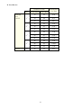
7. When installing new pistons or cylinders, the piston clearance should be checked and adjusted for proper
operation. Check the piston clearance at the skirt of the piston and just above the ports in the cylinder.
• Correct piston clearance for cast iron cylinders: .002 – .003 (50, 60 Spt), .0025 – .004 (90STD, T, M.)
• Correct piston clearance for aluminum cylinders .0015 – .0025 (90SPT, 175DT)
On cast iron cylinders, the cylinder can be honed to adjust clearance.
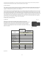
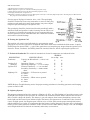
On aluminum cylinders, the piston must be polished to adjust clearance. Pistons are identified on top of the
pistons as follows:
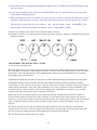
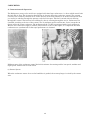
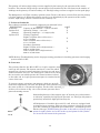
CRANKSHAFT AND ROTARY DISC VALVES
A. Construction and Operation
When the piston moves up and down in the cylinder from the force of the explosion of fuel/air mixture gas,
the crankshaft converts this reciprocating movement to rotary motion and supplies power to the rear wheel
through the clutch and transmission. The crankshaft must endure the impact of explosive force and the
high temperatures of combustion.
Crankshaft strength and precision are required to endure continuous high speed operation for long times.
Crankshaft materials must be selected carefully and machined exactly to prevent twisting, cracking,
offcentering, etc. The amount and direction, vertical or horizontal, of engine vibration has extreme affect on
riding comfort and fatigue of the rider. The crankshaft is one source of vibration. If the crankshaft is not
balanced properly, engine vibration will increase. Bridgestone crankshafts are designed to give smooth
rotation and balanced operation with a minimum of vibration.
Rotary disc valves are installed between the carburetors and the crankcase and control the supply of
fuel/air mixture from the carburetors to the crankcase. In conventional two-stroke engines, the fuel/air
mixture is controlled by the skirt of the piston and port timing, the opening and closing of inlet and exhaust
ports, is limited to before top dead center and after top dead center so that fuel mixture supply is not
efficient.
By using a rotary disc valve, the best timing for engine operation can be determined by altering the
cutaway of the valve disc, so that fuel supply and engine power are increased. Carburetor blow-back and
fuel loss can also be eliminated and engine performance increased tremendously.
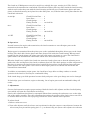
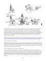
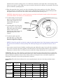
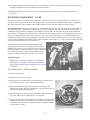
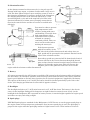
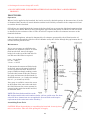
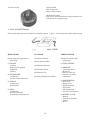
Fig. 55. Cross section of rotary disc valve engine
27
Fig. 56. Component parts of rotary disc valve
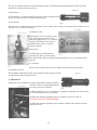
B. Rotary Valve Modification
The rotary valves were redesigned early in 1965 to eliminate the steel hub which was formerly molded into
the valve disc.
The valve now fits onto a separate splined collar. Old style valves can be replaced by the new style valves
by also installing the new splined collar and a new (shorter) crankshaft drive pin.
FOR 50-60 SPORT, 90 & 90 SPORT
Because of the new 2-piece design, valve timing must be aligned when installing a new style valve. The
collar has a slot that is easily aligned on the pin in the crankshaft.
The rotary valve must be installed on the collar with the "dot" mark on the valve aligned with the "dot"
mark on the collar.
Fig. 59.
28
FOR THE 175 DUAL TWIN
The rotary valve used on the 175 Dual Twin is interchangeable for either left or right side and must be
timed accordingly when installed. The valves are marked with an L and R.
The appropriate mark is aligned with the key slot in the crankshaft collar depending on whether the valve
is being used on the Left or Right side of the engine.
KICK STARTER MECHANISM:
Construction and Operation.
All Bridgestone rotary valve models are equipped with the primary kick starting system. In this method,
the engine can be started in any gear by simply squeezing the clutch. This is possible because this system
employs an extra set of gears for by-passing the clutch in starting the engine. This is a decided advantage
since it is not necessary to seek out neutral gear in order to start the engine.
29
50 Sport, 60 Sport and 90cc
KICK MECHANISM:
As shown in Figure 62, the kick idle gear A meshes with the driven gear, kick idle gear B meshes with kick
idle gear A, and the kick gear meshes with kick idle gear B. Since the kick gear is always in mesh with kick
idle gear B, the force created by turning the kick pedal is transmitted from kick gear, through kick idle
gear B, kick idle gear A, driven gear and pinion gear, to the crankshaft and starts the engine.
30
CLUTCH:
A. Construction:
31
The clutch on all Bridgestone rotary disc models is a multiple disc type, running in oil. The clutch is
mounted on the transmission countershaft. Clutch friction (fiber) plates are fitted inside the clutch housing
with six teeth so that they turn with the clutch housing and driven gear. Clutch friction plates and inner
plates are fitted alternately (steel plate first, then fibre plate, etc.) with the inner (steel) plates fitted to the
clutch hub with teeth.
50, 60 Spt.
Clutch Friction Plate . .
Inner Plate . . . . . . . . . .
Clutch Springs . . . . . . .
Fitting Tension . . . . . .
3
3
6
110 inch lbs.
90 cc.
Clutch Friction Plate . .
Inner Plate . . . . . . . . . .
Clutch Springs . . . . . . .
Fitting Tension . . . . . .
5
5
6
120 inch lbs.
175 DT
Clutch Friction Plate . .
Inner Plate . . . . . . . . . .
Clutch Springs . . . . . . .
Fitting Tension . . . . . .
6
5
6
130 inch lbs.
B. Operation:
Located between the engine and transmission, the clutch transmits or cuts off engine power to the
transmission and rear wheel.
Engine power is transmitted from the pinion gear on the crankshaft through the driven gear on the clutch
housing. The clutch hub, friction plates and inner plates all fit inside the clutch housing. When pressed
together by the clutch springs, the plates come into solid contact and rotate as a unit. The clutch hub is
spline fitted to the transmission countershaft, which turns the transmission gears.
When the clutch lever is pulled, the clutch wire turns the clutch release arm so that the adjusting screw
pushes the roller and depresses the clutch set (thrust) plate ball. The clutch springs are then compressed so
that they do not press the clutch friction plates against the inner plates. As the friction plates and inner
plates separate, the inner plates cease to turn so that engine power is cut off from the clutch hub and
transmission countershaft.
In addition to transmitting engine power, the clutch has a large affect on riding comfort, so smooth
operation of the clutch is necessary for comfortable riding.
If the clutch drags, gear shift operation becomes faulty and gears or the gear change arm can be damaged.
If clutch slips, poor acceleration, engine overheating, loss of engine power and uncomfortable riding will
result.
C. Adjustment:
Correct clutch operation requires proper setting of both the clutch cable adjuster and the clutch adjusting
screw which acts upon the clutch throw-out bearing.
Clutch cable adjustment should not be attempted without first removing the carburetor cover on the right
side of the engine assembly. The cable adjustment determines the position of the clutch release arm and it
is essential that the release arm is properly positioned to assure smooth clutch operation.
To adjust clutch:
1. Remove carburetor cover.
2. Turn cable adjuster until the release arm is positioned so that the center-to-center distance between the
release arm pivot pin and the spring pin is 1 ¼" as shown in Fig. 65. (Screw cable adjuster in to shorten
32
the distance, out to increase the distance. When properly positioned, secure with cable adjuster lock
nut.)
3. Loosen clutch adjusting screw lock nut and turn screw in (clockwise) until you feel it just touch the
clutch throw-out bearing. Then turn screw out (counter-clockwise) ¼ turn.
4. Check clutch lever for correct free play (3/8"-5/8" at lever end). Turn adjusting screw as required for
correct free play. (Counter-clockwise for more free play; clockwise for less.)
5. Secure adjusting screw in correct position with lock nut. NOTE: The tool kit shipped with the machine
contains a special socket wrench with handle which fits adjusting screw lock nut. The design of this
wrench enables you to hold clutch adjusting screw in correct position with a screw driver while securing
the lock nut. This tool, incidentally, also serves as a screwdriver handle in cases where heavy pressure is
required. See Fig. 66.
No further adjustment should be made on the cable adjuster unless it stretches with age. Periodic clutch
adjustments should be made with the clutch adjusting screw only.
33
TRANSMISSION:
A. Construction and Operation (Fig. 67)
BS 50 60 Sport 90 cc
Transmission Mechanism in Neutral Gear Position.
The transmission in the rotary valve engines is of a constant mesh, rotary type, running in oil. In the 50, 60
Sport and 90 cc engines, the transmission is 4-speed. The 175 Dual Twin has a transmission which is both
rotary change type 4-speed and a return change type 5-speed, made active by a simple flip of a lever.
The transmission consists of two shafts: the countershaft (or clutch shaft) and the drive shaft. The gears on
the countershaft are referred to with the suffix letter "A", for example, "first gear A." The gears on the drive
shaft are referred to with the suffix letter "B", for example, "first gear B."
First gear A is a part of the countershaft. Second gear A slides on the splined portion of the countershaft.
Third gear A and fourth gear A rotate freely on the countershaft. These three spinning gears transmit
power when they are engaged by drive dogs on the gears next to them. (Fifth gear A on 175 DT is keyed to
the shaft.)
Fourth gear B and third gear B are fitted to the splined portion of the drive shaft and turn with the drive
shaft. Second gear B, first gear B (and fifth gear B on 175 DT) turn freely on the drive shaft. Third gear B
slides from side to side on the splined portion of the drive shaft and engages either first gear B or second
gear B by means of the drive dogs on the sides of the gear.
34
The gears are so installed that the drive dogs on one gear engage the holes in the gear next to it. Gears are
never installed with drive dogs facing each other. Also, the respective gears will fit only one shaft properly.
Hence, all gears will mesh and drive dogs will properly engage the neighboring gears.
B. Gear Shift Mechanism
The Gear Shift Mechanism consists of a shift drum-shift fork assembly, shift drum pawl and shift arm
assembly, drum stopper, gearshift shaft and shift pedal.
1. Shift drum-shift fork assembly.
The shift drum is cylindrical in shape and it has a spiral-like groove (two in 175DT) cut into its surface into
which the shift forks are fitted. The rotary motion of the shift drum is translated into side-to-side motion in
the shift forks as they move in the spiral groove. The shift forks, in turn, move the sliding transmission
gears from side to side, thus shifting the various gears in the drive train.
2. Shift Drum Pawl.
The shift drum pawl is attached to the shift arm and serves to rotate the shift drum by means of pulling or
pushing action on the shift pins attached to the end of the shift drum.
3. Drum Stopper.
The shift drum stopper holds the shift drum in position between gear shift operations by lodging between
the drum shift pins.
4. Gearshift shaft.
The gear shift shaft serves to connect the shift arm and shift pawl to the footoperated gearshift lever.
5. Gearshift Lever.
35
The gearshift lever is located on the left side of the cycle and is foot-operated. Each time the front of the
lever is depressed or lifted, the transmission is shifted either one gear up or down, respectively.
Pedal pushed down front with foot once showing
drum advanced one notch, (engaging 1st gear) 2nd,
3rd, 4th and Neutral follow in succession.
Back pedal tread pushed down with foot once
showing drum turned in the opposite direction and
shifting gear in reverse.
36
C. Gear Shift Operation:
The rotary valve engines are equipped with rotary-type shift mechanisms. Each time the shift pedal is
depressed with the toe, the transmission shifts one gear higher. Starting in neutral, if the pedal were
depressed and released 3 times, the transmission would shift from 1st to 2nd to 3rd to 4th and back to
neutral. Fig. 71. Depressing the rear portion of the pedal with the heel shifts the transmission down one
gear lower each time it is depressed.
The transmission in the 175 Dual Twin can easily be
switched from the rotary change type four speed (described
above) to the return change type five speed with overdrive
(left) by simply moving a sportshift lever. (NOTE: This
sportshift can be moved while in any gear except neutral.)
The gear change system components are installed in the left
crankcase cover so that maintenance, disassembling and
inspection are easy.
Bridgestone 175's manufactured before November, 1965, (Serial No. 16W02913)
were equipped with the old style shift drum on which there were two neutral positions. As illustrated above
right, one neutral was positioned between 1st and 2nd gear, the other between 4th and 5th gears.
Fifth gear B is put into play by putting the "Sportshift" lever in the 5-speed position and depressing the
shift pedal. Turning the lever positions the guide pin in the 5th speed shift drum groove, thus connecting
the 5th gear shift fork to the shift drum. When the shift pedal is depressed, the drive dogs on 5th gear B (a
free spinning gear) engage the drive dogs on the drive shaft, thus transferring power from 5th gear A, which
is keyed to the clutch shaft, to the drive shaft.
37
The fifth speed shift fork on B/S 175 has been modified after serial No. l6B04739. The changes include a
guide pin in the crankcase, a new shift fork and 5th gear B. The new shift fork and gear are interchangeable
in sets only. When installed in old style crankcase, the shift fork is not connected to a pin.
First Gear:
With the First Gear A on the countershaft remaining in position, the Third Gear B on the driveshaft slides
to the right and the claws engage with the First Gear B.
Engine power is transmitted in the order of driven gear-clutch-countershaft-First Gear A-First Gear
B-Third Gear B-driveshaft and drive sprocket.
Second Gear:
38
The second Gear A remaining in position, the Third Gear B slides to the left and the claws on this gear
engage with the Second Gear B.
The engine power is transmitted in the order of driven gear-clutch-countershaft-Second Gear A-Second
Gear B-Third Gear B-driveshaft and drive sprocket.
Third Gear:
With the Third Gear B on the drive shaft remaining in position, the Second Gear A slides to the right and
engages with the claws on the Third Gear A.
The engine power is transmitted in the order of driven gear – clutch – countershaft – Second Gear A –
Third Gear A – Third Gear B – driveshaft and drive sprocket.
39
Fourth Gear:
The third Gear B remaining in position, the Second Gear A slides to the left and the dog teeth engage with
the Fourth Gear A.
The engine power is transmitted in the order of driven gear-clutch-countershaft-Second Gear A-Fourth
Gear A-Fourth Gear B-driveshaft and drive sprocket.
Fifth Gear:
The Fifth Gear is engaged with driveshaft by shifting "Sportshift" lever.
40
D. Gear Ratios:
Number of Teeth
Gear
50,60 Spt.
90 cc
175 DT
1st
2nd
3rd
4th
175 DT
5th
Transmission
Gear Ratio
Countershaft
Drive Shaft
13
38
2.92
13
36
2.77
13
34
2.61
18
33
1.83
18
31
1.72
18
30
1.67
22
29
1.32
22
27
1.23
21
26
1.24
26
26
1.00
26
24
0.924
24
24
1.00
26
22
0.85
41
CARBURETOR:
A. Construction and Operation:
The Bridgestone rotary valve models are equipped with Amal-type carburetors, i.e. those which control both
the fuel and air flow. The air passing through the air cleaner enters the carburetor venturi. The vacuum
created in the venturi by this flow of air causes the fuel in the float chamber to be drawn through the main
jet, needle jet and then through the passage to the fuel inlet port. This fuel is mixed with air entering
through the venturi. The fuel has been atomized by the air entering through the air jet. Carburetors are
classified according to the size of the venturi. The 50, 60 Sport models and the 90cc series (except the 90
Sport) utilize the 15mm carburetor. The 90 Sport and the 175 DT are equipped with 17mm carburetors.
Because two carburetors supply a mixture of fuel and air to the 175 DT engine, it is important that both
carburetors are synchronized so that equal performance is obtained.
Different parts of the carburetor control the fuel/air mixture for starting and for low speeds, medium and
high speeds. Instructions for each follow:
(1) Starter System
When the carburetor starter lever on the handlebar is pushed, the starter plunger is raised by the starter
wire.
42
When the kick starter lever is depressed with the throttle valve closed, air induction is generated behind
the throttle valve by the engine suction. This condition is similar to that created when the choke of a
conventional carburetor is fully closed. As the throttle valve is closed, air is inhaled only through the
starter air channel. Strong air induction is generated at the fuel jet located at the narrow starter plunger.
Fuel in the float chamber is metered by the starter jet and moves up the emulsion tube. Air is inhaled from
the wall of the tube and a rich mixture of air and gasoline is made. When secondary air is added to this
mixture, a correct rich mixture for starting a cold engine is inhaled into the engine through the nozzle
located behind the main bore.
NOTE: It is most important that the throttle valve be left closed when starting the engine. If it is not, the
rich gasoline/air mixture will be leaned out. Too, the raising of the throttle valve hampers the inhalation of
this correct mixture by taking away the vacuum ordinarily created when the kick starter is depressed.
(2) Slow channel (mainly for idling)
The suction stroke of the piston induces air at the pilot outlet of the carburetor so that gasoline is metered
through the pilot jet and air is drawn through the pilot air hole and metered by the air adjusting screw. The
gasoline and air make a rich fuel mixture which jets from the pilot outlet into the main bore where it mixes
with a small amount of air and is supplied to the engine, along with a correct amount of oil injected into the
intake between the carburetor and the engine.
(3) Main Channel (mainly for medium and high speeds)
Air entering the carburetor from the air cleaner passes under the throttle valve and is inhaled into the
engine as the main air flow. Induction is created at the needle jet by this main air flow and gasoline in the
float chamber is metered by the main jet and enters the needle jet. This gasoline passes through the gap
between the needle jet and jet needle and flows into the main bore of the carburetor. The gap between the
needle jet and the jet needle is controlled by the throttle grip, so that when it is opened the gap increases
and the flow of gasoline increases and when it is closed the gap decreases and the flow of gasoline also
decreases.
43
Air which enters through the air jet mixes with the gasoline from the main jet in the needle jet and it is
atomized when mixed with the main air flow and flows into the engine.
(4) Float Chamber
The carburetor makes a proper gasoline/air mixture according to the throttle opening and engine speed. To
create this proper gasoline/air mixture, the supply of gasoline must remain constant. The float chamber
supplies a constant flow of gasoline to the carburetor.
Gasoline flows from the tank through the pipe to the carburetor banjo bolt and between the valve seat and
valve to enter the float chamber. When gasoline enters the float chamber, the float moves up to stay on top
of the gasoline and pushes the valve closed with the valve arm. When the valve touches the valve seat, the
flow of gasoline stops. When gasoline in the float chamber is consumed and the level lowers, the float moves
down and the float arm no longer presses against the valve, allowing it to move away from the valve seat
and gasoline to enter the float chamber between the valve and valve seat. These procedures are repeated
and a constant level of gasoline is kept in the float chamber.
B. Functions of Various Parts:
(1) Main Jet
The main jet controls the fuel supply when the throttle is more than
threequarters open, but at smaller throttle openings although the fuel passes
through the main jet the amount is diminished by the tapered needle jet.
Listed below are the carburetor main jet sizes that are used as standard
equipment on the Bridgestone rotary valve models. Also listed are other sizes
that are available.
ORIGINAL
EQUIPMENT
MODEL
AVAILABLE
Main jet number
15mm Carburetor
110
56-60 Sport
100
90 before 12N
130
90 12N and after
120
90 Trail
130
90 Mountain
130
100
17mm Carburetor
90 Sp before 14L
95
Set of 5 (110-150)
90 Sp 14L and after
100
Set of 5 (110-150)
175DT
100
Set of 5 (110-150)
(2) Air Jet
44
The air jet controls the flow of air entering the needle jet. The fuel passing through the needle jet mixes
with the air coming in from the air jet.
(3) Needle Jet
At full throttle or at medium speeds, the fuel is first regulated by the
main jet and the needle jet acting simultaneously.
(4) Jet Needle
The tapered jet needle attached to the throttle valve works in the needle jet and adjusts the air/fuel ratio at
medium (¼ to ¾) throttle openings.
(5) Throttle Valve
The throttle valve is cut away on the
inlet side and controls the flow of
main fuel supply from c to ¾ throttle
opening. The extent of cut away is
marked on the valve, viz. 2.0 for
2.0m/m cut away.
(6) Pilot Jet
At idling speed or small throttle
openings, the pilot jet controls the
flow of fuel mixed with air which enters through the air jet, and atomizes the
mixture.
(7) Air Screw
through the pilot jet.
The air screw controls the flow of air which mixes with the fuel passing
The standard adjustment of this screw position for the various models
is stated below under Adjustment (3).
C. Adjustment:
Carburetors on all models are factory adjusted for proper operation
and idle. In the event idle adjustment is
necessary, proceed as follows:
(1) Run engine for at least 3 minutes in a properly ventilated area. Idle cannot
be correctly adjusted on a cold engine.
(2) Turn idle mixture adjusting screw in clockwise as far as it will go.
CAUTION: DO NOT OVER-TIGHTEN!
(3) Turn idle mixture adjusting screw counter-clockwise the number of turns
indicated below:
45
MODEL
ADJUSTMENT
BS 50-60 Sport
1¾ turns
BS 90STD, 90D, 90T, 90M 1¾ turns
BS 90 Sport
1½ turns
BS 175 DT
1½ turns
(4) With the engine running, adjust idle speed with idle speed adjusting screw
to the lowest RPM possible without stalling engine.
(5) Turn idle mixture screw 1/2 turn in either direction until point is found
where idle RPM is highest.
(6) Re-adjust idle speed screw for best idle speed.
TO ADJUST FLOAT LEVEL:
(1) Remove float bowl cover.
(2) Remove float bowl cover gasket.
(3) Holding carburetor upside down (float valve closed)measure distance between gasket seat and top of
float with a vernier scale. Correct distances are as follows:
MODEL
FLOAT LEVEL SETTING
BS 30-60 Sport
25/32 inch
BS 90STD, 90D, 90T, 90M 25/32 inch
BS 90 Sport
23/32 inch
BS 175 DT
23/32 inch
(4) Make adjustments in float level by bending only the brass tab which acts
upon float level. On dual float carburetors, make certain both floats are equal
before setting the float level.
Medium Engine Speeds Adjustment:
The gasoline/air mixture can be adjusted by raising or lowering the jet needle at c - ¾ throttle openings for
medium engine speeds. Standard setting is in the third groove from the top. The throttle valve cutaway also
affects engine operation at below c throttle opening, so do not change throttle valve cutaway for only
medium speeds adjustment.
It is recommended to raise or lower the jet needle for medium engine speeds adjustment within the range
where acceleration is not adversely affected.
High Engine Speeds Adjustment:
The performance of the engine between ¾ and full throttle can be adjusted by changing the main jet. A
higher numbered jet provides a larger orifice and, conversely, a smaller numbered jet provides a smaller
orifice. The jet number appears stamped on the side of the jet.
46
OIL INJECTION SYSTEM – 90cc
In the conventional two-stroke engine, a fuel mixture of
gasoline and lubricating oil is used so that parts inside the
engine are lubricated by oil contained in the fuel mixture. In
the Bridgestone Oil Injection System, a premixed fuel is not
necessary; gasoline and oil are supplied separately to the
engine. Gasoline is supplied through a carburetor as in the
conventional system.
A. Construction and Operation:
The oil injection pump is installed in the transmission case.
The pump works as follows:
The worm wheel of the pump is driven through:
Crank shaft – Drive pinion – Pump Gear B
The worm wheel, the boss of which is cam-shaped, is in addition to being rotated by the pump drive shaft,
pushed in direction B by the plunger spring and contacts the rod (c) as shown in Fig. 96. The worm wheel
plunger slides in the direction of (a) or (b) shown by arrows in Fig. 96 and 98, following the cam height.
1. Oil Intake:
When the worm wheel contacts the rod (c) at the highest point of the
cam, the volume of the pump chamber increases and the pressure in
the chamber (Fig. 99) decreases and releases the inlet check ball. The
inlet port opens and oil is sucked into the oil pump chamber.
2. Oil Outlet:
When the worm wheel plunger slides in the direction (b) illustrated
by the arrow in Fig. 98 the volume of the pump chamber decreases.
By decreasing the volume of pump chamber, the inlet check ball
closes the inlet port and the outlet check ball opens the outlet port.
Oil is forced into the crankcase.
3. Operation of Worm Wheel Plunger in Relation to
Throttle Grip:
(a) Slow speed—idling:
When the throttle grip is in zero position, i.e.
throttle grip is in closed position, the rod (c)
contacts the control lever at its lowest position. The
worm wheel plunger slides to the left (arrow "a")
and the plunger contacts the adjusting screw as
shown in Fig. 98. The distance of shift of the
plunger to the adjusting screw (d) is shortened to
less than the height of the worm wheel cam,
thereby reducing the volume of oil.
(b) High speed — wide open throttle:
47
When the throttle grip is wide open, the cam of the control lever contacts the rod (c) at its highest point,
thereby shifting the rod (c) to the right (arrow A).
The distance of shift of the plunger is lengthened, and the volume of oil increased.
B. Adjustment:
The oil pumps used on B/S 90 machines are factory adjusted for the proper amount of oil and should never
need adjusting. The only time adjusting should be necessary is when a customer or an unauthorized
personnel may have tampered with the adjustment.
If the setting needs adjusting, proceed as follows:
Note: Use extreme care when making this adjustment and follow these instructions exactly.
TO REMOVE AND DISASSEMBLE THE PUMP
•
Remove the 2 pump mounting screws.
•
Disconnect the pump control cable from the control arm.
•
Disconnect the inlet and outlet oil lines from the pump. Caution: Care must be used not to lose the balls
and springs from the connecting bolts.
•
Remove the pump from the engine.
•
Disassemble the pump by removing 3 pump housing screws and separate the two pump halves.
Caution: Locate the spring in the end of the pump gear so that it does not become lost.
TO ADJUST THE PUMP
1. Hold the pump in the position shown below and
revolve the pump gear so that the highest point of
its earned edge "A" is in contact with the stop pin
"B".
2. Loosen the adjusting screw lock nut "C'
3. Turn the adjusting screw "D" in (clockwise) until it
pushes the pump gear out just to the point where
the stop pin "B" is just contacting the high point of
the cam "A". Check by revolving the pump gear
while holding it in against the adjusting screw, to
see that the gear does not move in and out when it
moves from the high to the low point of the cam.
The stop pin "B" should just touch the high point of
the cam when it is revolved.
4. When the screw "D" has been set so that the stop
pin "B" is just touching the high point of the cam, turn the adjusting screw "D" out (counterclockwise)
exactly ¾ of a turn and secure with the locknut "C".
The pump is now correctly adjusted for all driving speeds.
TO REASSEMBLE THE PUMP
1. Install the gear spring into the pump gear.
48
2. Assemble the gear case gasket and housing in place and reinstall 3 screws, fastening securely.
3. Place a small quantity of oil in the gear case housing and reassemble the pump onto the engine, but do
not install the mounting screws.
4. Reconnect the inlet and outlet oil lines.
(a) The brass connecting bolt and spring must be used on the inlet line.
• The spring must be installed first into the pump and then the check ball.
• NOTE: Only a brass connector bolt can be used in this port.
(b) The steel connecting bolt and spring must be used only on the outlet line.
• The check ball is installed first into the pump and then
the spring.
• NOTE: Only a steel connector bolt can be used in this
port.
5. When assembling the oil line onto the rotary valve
cover, a steel connector bolt must be used.
6. Do not over tighten the connecting bolts.
7. Install the 2 pump mounting screws and tighten
securely.
8. Connect the control cable to the pump and check its adjustment.
• With the throttle completely closed, the oil pump outer cable should have 1/16 of an inch of free play at
the oil pump cable stop pin. Adjustment is made by the cable adjuster located in the cable by the
transmission oil filter plug.
9. If, after adjusting the pump according to the above instructions, it appears that it is pumping too much
oil, without removing the pump, loosen lock nut "C" and turn the adjusting screw "D" clockwise a slight
amount. Never adjust more than c turn at a time until the cycle is operated and again check..
C. Special Attention to the Oil Injection System:
The following procedures are necessary after filling up the oil tank before break-in or after disassembling
oil tank or pump.
1. Remove the carburetor cover by screwing out the 4 carburetor cover screws.
2. The oil inlet tube (black) and the oil tube (transparent), which are connected to the oil pump, are shown
in Fig. 109
3. The oil outlet tube (transparent) is connected to the rotary valve cover.
• Procedures 4 and 5 are necessary to exhaust any air bubbles from the rotary valve cover, and obtain free
flow of oil from the pump to the outlet tube.
4. Loosen the oil inlet union bolt one or two turns, (do not take out this bolt) and pump oil out from the
union bolt on oil tube (black) connecting oil tank and oil pump, by pinching the oil tube alternately with
fingers of both hands as shown in Fig. 109
49
• NOTE: Pinch part A first, then
pinch part B; repeat alternately
until air bubbles are eliminated and
the oil flows freely out of the union
bolt.
5. Tighten the oil inlet union bolt and
repeat pinching with fingers; check
the oil flow in the outlet tube
(transparent) to the inlet in the
rotary valve cover.
• If there is no oil flow in the outlet
tube (transparent), repeat
procedure 4.
A simple check of the oil injection
system can prevent serious damage
when the machine is operated. Dirty or plugged oil lines, tanks, or filter could prevent the oil flow from the
oil tank to the pump.
Whenever a new cycle is serviced, the oil supply line to the pump should be removed at the pump and
checked for oil flow.
If a good supply of oil is not available at this line, check the tank, filter and lines and correct as necessary.
Oil must flow freely from this line to supply the engine with the proper lubrication.
OIL INJECTION SYSTEM – 175DT
A. Construction and Operation:
Lubricating oil is supplied by an oil pump attached to
the left rotary valve cover. Oil pump gear B, attached to
the pump drive shaft, is driven by gear A, located on the
left end of the crankshaft.
The oil pump Drive Shaft drives the pump plunger
through a worm gear arrangement. The speed at which
the Plunger rotates, then, is determined by crankshaft
RPM. There is a 12:1 reduction in the gearing between
the crankshaft and the pump drive shaft.
In addition to being rotated by the pump drive shaft, the
Plunger moves up and down in the pump body. This
reciprocating
motion is produced by the cam-shaped lower end of the Plunger
bearing against the Plunger Guide.
The Plunger is held against the Plunger guide by the spring-loaded
Differential Plunger which bears against the top of the Plunger.
The length of the Plunger stroke is determined by the position of
the Stop cam in the lower end of the Pump Body. The stop cam is
part of the control arm assembly which is connected by means of a
control cable to the throttle grip.
50
When the throttle is closed, the lobe of the stop cam limits the down
stroke of the Plunger resulting in a short stroke. This short stroke of
the Plunger reduces the amount of oil pumped at idle.
As the throttle is opened, the Control Arm rotates the eccentric Stop
Cam so that the length of the Plunger's stroke is progressively
increased, resulting in an increased volume of oil being pumped to the
injectors.
OIL INTAKE
The diameter of the Plunger is slightly larger
than the diameter of the Differential Plunger.
The pumping action takes place in the area
surrounding the Differential Plunger in the oil
pump body.
As the plunger moves downward in the pump body, this area is increased in volume
and a partial vacuum is produced. The rotation of the plunger (as it moves
downward in the pump body) allows the inlet hole in the plunger to align itself with
the Oil Inlet leading from the supply tank. This is drawn up through the Plunger
and out the hole in its top and into the areas surrounding the Differential Plunger.
OIL DISCHARGE
When the rotating Plunger moves UP in the oil pump body,
the area surrounding the Differential Plunger is decreased
in size and the compressed oil re-enters the hole in the top
of the plunger and is discharged through the left or right oil outlet. The rotation of
the Plunger has aligned the oil outlet port in the Plunger with an oil outlet in the
pump body. These outlets are located 180E apart in the pump body and are ducted
to the oil line fittings on the front of the pump.
The timing of the alternating alignment of inlet and outlet ports in the Plunger is
predetermined by the cam-shaped lower end of the plunger.
It is thus seen that oil pump output volume is regulated both by crankshaft speed
and throttle setting.
B. Adjustment
The entire oil injection system is designed to provide the correct oil mixture at all speeds.
The only adjustment it will ever need is the cable adjustment. The oil pump volume is
affected by the position of the throttle and varies from 20 to 1 mixture at full throttle to
100 to 1 at idle. To adjust the oil pump control cable proceed as follows:
1. Remove left carburetor cover.
2. Turn throttle grip to maximum open position.
3. Check the oil pump control arm (where the cable is connected) and note the pin in the oil
pump body and 2 stops on the control arm. (Fig. 107). At the maximum open throttle
position the stop should be within c inch of the stop pin. If the stop clearance is open
more than c inch or the stop is closed against the pin, adjustment is necessary.
51
4. Cable adjustment is made at the cable
adjusting screw located above the left
carburetor housing, directly in front of the
generator. Loosen cable adjusting screw
lock nut and turn adjusting screw in for
additional stop clearance and out for less
until l/g inch of stop clearance is observed
with the throttle at maximum open
position.
NOTE:
1. Do not adjust to less than c inch
clearance.
2. When throttle is closed after adjustment,
the oil pump control arm may not return
to its closed position and may appear to be
faulty. However, the oil pressure in the
pump sometimes holds the control arm
open when it is operated without the engine running. This can be checked by running the engine or
operating the kick starter.
C. Special Attention — Pump Modification
Bridgestone 175 Dual-Twins manufactured after October, 1965, are equipped with a modified oil injection
pump. The new pump is equipped with ball and spring check valves in each of the pump body oil outlets.
The springs fit inside the union bolts which are unchanged from previous models.
DISMANTLING OIL PUMP
1. Ball check valves are installed only in the outlet ports (Never
in the inlet port.)
2. Ball check valves cannot be installed in the old style pumps
that were not originally equipped with them.
3. When assembling the unit, first install the ball in the outlet
port hole. Next, install the spring into the union bolt. Then
with the oil line connector and picking washers installed on
the bolt, screw the bolt into the outlet port hole.
4. The style of oil pump can be determined by viewing into the outlet port holes. The outlets on the old style
pumps have no ball valve seats machined in them and the check
ball will pass through the outlet, into the oil pump body.
• The new style pumps have check ball valve seats machined in the
outlet ports.
5. New style oil pump assemblies are interchangeable with the old
style assembly. An additional change was made in Feb., 1966,
Serial No. 16B. This change incorporates the ball and spring check
valves into a new style outlet connector.
The ball and spring are assembled inside of the new connector and
eliminate the possibility of incorrect assembly or loss of these parts.
52
The new connectors are easily identified because they are made of brass instead of aluminum. These new
connectors are interchangeable on any of the old type pumps. When they are installed on old type pumps,
the ball and spring must be eliminated from the connecting bolts.
Any old type pump can be converted to the latest style by installing 2 of these new outlet connectors. The
old type union connector has been abolished.
A simple check of the oil injection system can prevent serious damage when the machine is operated. Dirty
or plugged oil lines, tanks, or filter could prevent the oil flow from the oil tank to the pump.
Whenever a new cycle is serviced, the oil supply line to the pump should be removed at the pump and
checked for oil flow.
If a good supply of oil is not available at this line, check the tank, filter and lines and correct as necessary.
Oil must flow freely from this line to supply the engine with the proper lubrication.
ELECTRICAL EQUIPMENT – 50, 60 Sport, 90cc
A. Ignition System:
The ignition system consists of a single magneto coil to
provide the necessary current, a condenser, contact breaker
assembly, an externally mounted dual winding high
tension coil, and spark plug.
Contact Breaker:
The contact breaker assembly is mounted on the magneto
armature plate. The actuating cam is located on the
crankshaft. The contact points should be checked
periodically. If the contact points are rough or pitted,
replace them. When installing new contact points, carefully
wipe the surfaces with a lint free paper to remove any
residue of grease from the point surfaces which will
drastically affect the functioning of the ignition system.
Ignition Timing: Incorrect ignition timing can cause problems not directly related to ignition such as poor
fuel consumption, overheating, hard starting when engine is hot, spark plug burning or fouling, and even
extreme engine damage. Therefore, when diagnosing an engine problem, always check and adjust timing
first.
CAUTION: Never, under any circumstances, should an engine be run with advanced timing. There is,
however no danger in running the engine with the ignition slightly retarded. In fact, higher RPM and
increased performance will be attained if timing is retarded 2 degrees from the factory setting.
TO SET TIMING:
1. Remove the magneto case cover and locate the timing marks. One mark is engraved on the side of the
flywheel and the stationary mark is a cast "pointer" on the magneto case cover. (See Fig. 111)
2. Rotate flywheel until points are visible through opening in flywheel and timing marks are approximately
aligned.
3. Connect one lead of an ohm meter and continuity tester to one of the black wires leading from the
magneto. Connect the other lead to any convenient ground on the machine.
4. Position the flywheel timing mark above the magneto case (stationary) mark. Very slowly rotate the
flywheel in a counter-clockwise direction (direction of engine rotation) and stop precisely at the point at
53
which the lowest meter reading occurs or at which the continuity tester light dims. (Note that the ohm
meter never reads "0" or the light never goes out entirely because the condenser is grounded). This is the
point at which the spark plug fires.
5. When this point has been located, note the relationship of the timing marks to each other. The best
setting is about 2E retarded from the ignition angle established by the perfectly aligned timing marks.
The ignition mark is 3/32" below the center of the stationary mark, (See Fig. 113)
• CAUTION: adjustments must be made if ignition occurs before the flywheel mark reaches the magneto
case mark. (In this case timing is too far advanced.)
6. To adjust timing, measure point
gap at its widest open position.
(The timing marks will not be
aligned when this gap is
measured.)
a. To retard spark, close the point
gap by .001" at a time until the
light dims (when the flywheel
mark is 3/32" below the
magneto case mark. Secure the
point adjusting screw and
recheck.
b. To advance spark, open the
point gap .001" at a time until
the tester light dims when the
marks are aligned as in Fig.113.
• NOTE: It should be possible to time the engine by point adjustment alone if the magneto armature plate
has not been moved from its factory setting. The contact point gap can be anywhere between .012 to
.016".
• If the engine cannot be timed with the resulting point gap within this range, loosen the three armature
plate screws and move the plate slightly in the direction you want the flywheel mark to move for proper
alignment as shown in Fig. 113. Then proceed to make fine timing adjustments as set forth above.
Condenser: (Fig. 111 ) The condenser is mounted on the armature plate and its function is to absorb the
current generated when the contact breaker points open. It also assists the functioning of the ignition coil.
Always check the condenser whenever the contact points are changed in the event that it might need
changing too should it not meet the specifications required.
Spark Plug: The table below indicates the correct spark plugs for the 90cc. 50cc Sport and 60cc Sport
models:
MODEL
BS-5OSport
BS-60Sport
BS-90
BS-90 Trail
BS-90
Mountain
USE CODE
C
B-8C
D
B-8C
E
B-8N
J8 or J8J
J62R
J60R
J57R
B-7H
B-6H
B-7HC or B-
B-
B-
Champion
L62R
L7
L-60R
L57R
L-54R
NGK
B-7H
B-6H or B-
B-7HC or B-
B-
B-
Champion
L62R
L7
L60R
L57R
L-54R
PLUG
BRAND
NGK
B-7
B-6
Champion
J4 or
NGK
A
B
54
KEY TO USE CODE:
A Standard plug for break-in and normal use.
B Hotter plug for low speed use and when standard plug fouls easily.
C Colder plug for high speed use and when standard plug burns easily.
D Cold plug. Standard for competition use.
E Extremely cold plug for high speed racing. Will operate well only at extremely high temperatures. Starting may be difficult with
this plug. Not recommended for normal use.
Correct gap on all plugs is between .024 – .027". The spark plug
should be checked at least every 2,000 miles. A worn or dirty plug
produces weak spark and causes hard starting, low power output,
irregular rpm and damage to the ignition coil.
The spark plug should be checked and cleaned periodically with a
stiff wire brush and gasoline or other cleaning solvent. The use of
an abrasive in cleaning the spark plug is not recommended since
abrasive particles may be introduced into the combustion chamber
and result in cylinder damage.
B. Testing the Ignition Coil:
The ignition coil can be tested efficiently by connecting the spark
plug cap to one lead of a gap tester. Ground the other lead of the tester and kick the kick starter. A spark
should jump the quarter-inch ( ¼ ) gap. If the spark does not jump this gap, suspect that the ignition coil is
defective. Points, condenser, and timing should be checked, however, before replacing the ignition coil.
C. Technical Standards: The technical standards of electrical components are indicated below:
MODELS
DESCRIPTION
SPECIFICATIONS
50, 60 Spt 90cc
Condenser
Capacity in Microfarads — 0.25 to 0.30
X
X
mfd
Ignition Coil
Operating Voltage — 0.5 volt
X
X
(Primary)
Operating Amperage — 1.5 to 2.5 amps
X
X
Ignition Coil
Primary Continuity — 1.5 to 2.0 ohms
X
X
Secondary Continuity — 8000 to 9000
X
X
ohms
Lighting Coil
Continuity — Yellow wire to ground
0.2 ohms
X
0.5 ohms
X
Continuity — White wire to ground
0.1 ohms
X
0.5 ohms
X
NOTE: Refer to Troubleshooting section for proper testing procedures in checking generator and charging
system on B/S 175 DT.
D. Lighting System:
The magneto armature plate also contains a lighting coil. (Fig. 111) The lighting coil provides current to the
headlight and taillight. It also provides AC current to the selenium rectifier which converts this current to
DC to "trickle" charge the battery. The battery is a 6 volt-4ampere hour battery furnishing current to the
brake light and the neutral gear indicator light. The battery also functions as a stabilizer in the electrical
circuit. At high speeds, the magneto puts out from 12 to 18 volts. This current passes through the battery
which stabilizes it at 6 volts. It is important that the battery is fully charged at all times since a discharged
battery will not offer sufficient resistance in the electrical circuit. When battery charge is low, the headlight
and taillight bulbs will be burned out instantly when they are turned on.
55
E. Testing the Lighting Coil:
The efficiency of the lighting coil can be checked by
connecting an ammeter of approximately 2 ampere reading
capacity in series with the battery fuse as indicated in the
drawing below.
Start the engine and measure the current at approximately
2,500 rpm's and approximately 8,000 rpm's.
With the key switch in the "ignition only" position, at 2,500
rpm the current should measure 0.1 amp. Voltage should
register more than 6 volts. At 8,000 rpm's, the voltage
should register less than 9 volts. If the measurements are
within plus or minus 10 to 20 per cent of the standard rate
indicated, the coil is satisfactory. If it is above or below these tolerances, the lighting coil should be
replaced.
F. Selenium Rectifier:
The selenium rectifier transforms AC magneto into DC current for charging the battery.
Running the machine in the daytime without the battery or fuse in place will damage the rectifier and burn
out light bulbs. The battery should be kept fully charged. Specific gravity at approximately 70E F. should
read 1.260 on a fully charged battery.
G. Battery Charging (50-60 Spt)
Listed below are two methods of increasing the charge rate on the B/S 50-60 Sport.
1. Connect both the yellow wire and the white wire from the key switch to the yellow wire from the
charging coil in the magneto. The white wire from the magneto is left disconnected. This wiring change
will slightly increase the charging rate.
56
2. For chronic problems caused from the cycle being driven only at very low speeds, the charging coil from
the B/S 7 Standard can be installed to increase charging.
NOTE: When either method is used, battery water should be checked frequently and water added as
necessary.
ELECTRICAL EQUIPMENT – 175 DT
The ignition system consists of contact breakers, condensers, ignition coil, spark plugs, etc. Battery low
voltage current is converted to high voltage current by the ignition coil. High voltage current is supplied to
the spark plug and, when timed by the contact breakers, ignites the fuel mixture in the cylinder.
Contact Breakers: Two contact breakers are fitted on the AC dynamo. The AC dynamo is turned through
the pinion drive gear, driven gear and timing gear. The timing gear turns one full revolution when the
crankshaft turns two full revolutions. The timing gear and point cam are fixed on the dynamo shaft and
turn with it. The engine of the BS 175 DT is a two-stroke two cylinder engine so two explosions occur every
time the crankshaft makes one full revolution. As the speed of the AC dynamo is one-half of that of the
crankshaft, contact points must supply four sparks for each revolution of the dynamo, so two cams and two
sets of contact breakers are installed. One contact breaker opens each 90E (¼ turn) of cam rotation and high
voltage current is induced in the ignition coil.
Contact breaker points should be kept bright and
smooth. If point surfaces are rough or pitted, polish
lightly and evenly on an oil stone until the surfaces are
smooth. (If points cannot be repaired, replace with new
ones.) After polishing, wash the point surfaces with
gasoline or thinner and wipe dry with a clean cloth.
Ignition timing:
• NOTE: Do not attempt to adjust left timing until
right timing is completed. Movement of generator
during right cylinder timing adjustment will change
left timing.
TO CHECK TIMING - RIGHT CYLINDER
1. Remove spark plugs.
2. Remove left carburetor air pipe.
3. Remove point cover from left end of generator and adjust both
sets of points to .012"-.016" at their widest point.
4. Rotate crankshaft by putting transmission in 4th gear and
turning rear wheel until the right piston is at top dead center as
viewed through the spark plug hole.
5. Install timing screw and bar into timing hole at front of engine
(fig. 112). This item is packed in the cycle tool kit.
6. Connect one lead wire of a continuity test light to the right point
condenser lead wire at the condenser with the key switch in the
off position. (Test light is now off) The other test light lead wire
is grounded to engine.
57
• NOTE: As you face the open end of the generator, the points and condenser set on your right, control the
firing of the right cylinder. (See Figure 114.)
7. Rotate engine backwards by turning the rear wheel backwards until the right points close and test light
is on.
8. Now hold slight pressure on the timing bar and rotate the engine forward until the timing bar engages
the slot in the crankshaft. If the timing is correct, the test light will have just gone out at this point.
RIGHT CYLINDER TIMING ADJUSTMENT:
If the test light did not go out (timing is too slow or retarded) or went out before engagement of timing bar
(timing too fast or advanced) proceed as follows:
1. Remove air cleaner.
2. Loosen generator mounting clamp nut ("A", fig. 114)
3. Slightly loosen generator positioning screw ("B", fig. 114).
4. With the timing bar inserted into the crankshaft, rotate generator counter-clockwise to slow or retard the
timing or clockwise to advance the timing until the light has just gone out and retighten generator
position screw and clamp nut. Recheck timing by observing the light as the timing bar engages the slot
in the crankshaft. (It should just go out).
TO CHECK TIMING-LEFT CYLINDER:
1. Rotate engine by turning rear wheel until left piston is at top dead center as observed through spark plug
hole.
2. Connect one test light lead to left point condenser lead wire at the condenser. (The other test light lead is
grounded). The light is now off.
3. Rotate engine backwards by turning rear wheel backwards until the left points close and the test light is
on.
4. Now hold a slight pressure on the timing bar and rotate the engine forward until the timing bar engages
the slot in the crankshaft. If the timing is correct, the test light will have just gone out at this point.
LEFT CYLINDER TIMING ADJUSTMENT:
1. If the light did not go out (timing slow or retarded) or
if the light went out before engagement of the timing
bar (timing too fast or advanced) proceed as follows:
2. Loosen the 2 point timing plate screws ("A", fig. 116)
and, with the timing bar inserted into the
crankshaft, move the plate counter-clockwise (down)
to slow (retard) the timing or clockwise (up) to speed
up (advance) the timing until the light just goes out.
Retighten screws. Recheck timing by rotating the
engine and observing light as the timing bar
engages the slot in the crankshaft. (It should just go
out.)
B. Ignition Coils:
58
The ignition coil induces high voltage current supplied by the battery by the operation of the contact
breakers. The amount of high voltage current induced is determined by the ratio between the number of
windings on the primary coil and secondary coil. This high voltage current is supplied .to the spark plugs.
The Bridgestone 175 DT has a battery ignition system. Twelve volt battery current flows into the primary
coil of the ignition coil. When this primary current is cut off suddenly by the operation of the contact
breaker, high voltage current is induced in the secondary coil.
C. Technical Standards:
The technical standards of electrical components are indicated below:
DESCRIPTION
SPECIFICATIONS
Condenser
Capacity in Microfarads — 0.25 to 0.30 mfd
Ignition Coil
Operating Voltage — 12.0 volt
(Primary)
Operating Amperage — 1.5 amps (each)
Ignition Coil
Primary Continuity
Right Coil (White wire to blue wire) —
4.5 to 5.0 ohms
Left Coil (White wire to blue wire) —
4.5 to 5.0 ohms
Secondary Continuity
Right Coil (Blue wire to high tension) —
9000 to 10,000 ohms
Left Coil (Blue wire to high tension) —
9000 to 10,000 ohms
175DT
X
X
X
X
X
X
X
NOTE: Refer to Troubleshooting section for proper testing procedures in checking generator and charging
system on B/S 175 DT.
D. Generator:
The generator fitted to the BS 175 DT is a six pole, magnetic, inner
rotor type AC dynamo. The dynamo consists of a rotor into which
magnets are cast and a stator consisting of an iron core and wires
wound around the iron core. The timing gear is fitted on one end of
the rotor and a cam which operates the contact breakers is fitted
on the other end. A six pole permanent magnet is contained in the
center of the rotor.
To increase output, anisotripic cast magnets, which are specially
treated for magnetizing, are used. The principle of the generator is
the same as that of a conventional magneto, but the stator consists
of three coils as shown in Fig. 119, so the dynamo generates three
phase alternating current.
Outstanding features of the magneto type AC dynamo are good resistance
to vibration, capability for high speed operation, etc. This type of dynamo is
particularly suitable for high speed motorcycles.
All Bridgestone 175 models after serial No. 16G 11761 are equipped with
an improved type generator. This new style generator is driven by an extra
gear and is turning at crankshaft speed rather than ½ crankshaft speed as
did the older type. NOTE: Timing procedure is the same as old style except
points for right cylinder are located at the top and points for left cylinder
are located at the bottom of the generator.
59
E. Selenium Rectifier:
As the dynamo mounted on this motorcycle is a six pole type AC
Dynamo with large output, a selenium rectifier with a large area is
used. The three phase bridge all-wave rectifying system is used, so
that charging performance is excellent. As show in the illustration,
the charging current flows in the direction indicated by a solid
arrow during half a cycle and in the next half cycle flows in the
direction indicated by a broken arrow. Charging current always
flows in the same direction and the AC current is rectified most
effectively.
Care must be taken to prevent
high temperatures in the
rectifier, wetting with water
and handling. No trouble from
high temperatures will be
experienced if the rectifier is
mounted in a properly
ventilated position. Take care
not to wet the rectifier when
washing the motorcycle.
If the dynamo operates
with the secondary circuit
(DC side) of the rectifier disconnected and voltage rises too
high, sparks will be generated in the synthetic materials in the
layers of the selenium rectifier.
Spots where sparks are generated will be burned and electrical
current will flow in the reverse direction through the burned
parts so that electrical current from the battery will flow to the
ignition coil when the engine stops. This will decrease the
magnetic power of the generator. Take care not to run the
engine with the selenium rectifier disconnected.
F. Battery:
AC current generated by the AC Dynamo is rectified to DC current by the selenium rectifier and charged
into the battery. All current for operation of the motorcycle flows from the battery. The battery should be
kept in good condition at all times since electricity for all electrical equipment is supplied by the battery.
The capacity of the battery is 12 V-6 AH. The battery should be checked periodically by the rider or the
dealer. (See charging specifications for all models in opposite column.)
G. Headlight:
The headlight includes a 12 V, 35 W main beam and a 12 V, 25 W dim beam. The battery is the electric
source for the headlight. Riding will be dangerous at night if obstacles cannot be seen clearly. As the
headlight of the Bridgestone DT is operated on battery current, it remains bright regardless of engine speed
and riders can enjoy safe riding at night.
H. Spark plugs:
NGK B-8H spark plugs are standard for the Bridgestone 175 DT. Be sure to use the proper spark plugs as
the engine cannot develop 100 percent performance if an incorrect spark plug is used. The spark plug is
proper for the engine when the spark plug insulator is light brown in color. If the insulator is black or
60
carbon accumulates on it, use a hot type of spark plug, that is one with a smaller number. If the insulator
has a bleached appearance, use a cold type of spark plug, or one with a larger number.
BRAND
IF PLUG FOULS
EASILY (Slow Speed)
IF PLUG BURNS
EASILY (High Speed)
B-8 H
B-7 H
B-7 HC
B-8 HN
B-9 H
L-58 R
L-5
L-56 T
L-55 T
STANDARD
NGK
CHAMPION
Dry Charged Storage Batteries
ALL MODELS
The fully charged battery acts as a voltage stabilizer in the electrical system. Because the magneto delivers
considerably more current than the rated voltage of the system, a fully charged battery is essential as a
buffer between the current generating source and the various light bulbs on the cycle.
A discharged battery does not provide sufficient electrical resistance to perform this "buffer" function and
light bulbs will be burned out when they are switched on due to the excessive current reaching them from
the magneto or generator through the discharged battery. For this reason, it is important that the dealer
properly fill and charge the battery just prior to delivering the machine.
1. Fill the battery to proper level with 1.260 specific gravity electrolyte.
61
2. Allow battery to stand for 2-8 hours without charging.
3. Inspect liquid level and add more electrolyte, if necessary.
4. Measure specific gravity with a hydrometer. Table 1 indicates the approximate degree to which the
battery is charged (stated as percent charged) and the approximate ampere/hours of charge which will
be necessary to bring the battery to a fully charged condition.
CHG. REQ.
(IN AMP/HRS)
SP. GR.
%
1.260
100%
0
1.220
75%
18 A/H
1.160
50%
30 A/H
1.105
25%
45 A/H
CHARGE
D
• While it is theoretically possible, rarely, if ever, will a dry charged battery be found to be fully charged
when the electrolyte is added.
5. To charge the filled battery, a 2½ A/H charge rate may be used in the initial state of charging. The
charge is then completed with a ½ amp. trickle charge. The approximate charging time for each of these
two charge rates is indicated in Table 2. This table is based on the hydrometer reading taken in 4 above.
SP. GR @
70E
APPROX. CHG.
TIME
@ 2.5 A/H
@ 1/2 A/H
APPROX.
CHG
1.240
2 Hrs plus
10 Hrs
1.220
4 Hrs plus
20 Hrs
1.160
8 Hrs plus
20 Hrs
1.105
10 Hrs plus
30 Hrs
• NOTE: If battery case becomes hotter than 115E (warm to the touch) charge rate must be reduced
immediately. Overheating will cause severe battery damage.
• As a matter of practice, the maximum charge rate depends largely on the air temperature of the area
where the battery is being charged. A charge rate of up to 50% of the total charge required (see Table 1)
can be used IF TEMPERATURE OF THE BATTERY CASE DOES NOT RISE ABOVE THE POINT AT
WHICH IT IS JUST WARM TO THE TOUCH (115E F.). Therefore, the cooler the surrounding air
temperature, the higher the allowable charge rate.
CAUTION:
1. DO NOT OVERCHARGE. Take specific gravity readings frequently during charging period.
2. CONNECT CHARGER CORRECTLY. Positive lead to positive terminal; negative lead to negative
terminal.
62
3. Set charger for correct voltage (6V or 12V)
4. DO NOT LET FILLED, UNCHARGED BATTERY STAND LONGER THAN 12 HOURS BEFORE
CHARGING.
FRONT FORK:
Operation:
When a load is applied to the front fork, the load is received by the fork springs. At the same time, oil in the
oil chamber flows into the oil control chamber and the load is held by resistance of the compressed oil and
air and the shock is absorbed.
Oil lock bars are installed inside the bottom of the lower fork legs to prevent the fork from bottoming when
receiving severe shocks. When oil moves through the gap between the piston oil and the oil lock bar, shock
is absorbed by the resistance of the oil. The oil lock bar is tapered so that oil resistance increases as the
front fork shortens.
When the fork lengthens, rebound is dampened by oil resistance generated by the oil flow from the oil
control chamber through the oil hole to the oil chamber and by the oil flow through the gap between the oil
lock bar and the piston oil hole.
Maintenance:
If it is ever necessary to add fluid to the
front fork, use hydraulic jack oil. To insert
fluid into the fork, remove the upper
bridge bolt on the top of the fork tube. Do
not add more fluid than is required:
6 ozs. – 50, 60 Sport
6-7 ozs. – 90CC
7.5 ozs. – 175 DT
To determine the amount of fluid already
in the fork, remove the upper bridge bolt
on the top of the fork tube. Insert a wire
gauge of sufficient length, making certain
it touches the bottom of the tube. Remove
the gauge and measure the fluid mark. It
should measure 6 ½ to 7 inches (50, 60 Spt;
90) or 7 ½ to 8 inches (175 DT).
If no gauge is available, remove the screw
at the bottom of the outer tube and drain
the fluid. Reinsert the correct amount (in
ounces) for the particular model involved,
as indicated above.
NOTE: The front fork assemblies on the
B/S 50 Sport model with serial numbers before 13N are sealed units. For these
units the above instructions are not applicable. (Loss of fluid would require
replacement of the entire inner tube assembly. )
Assembling Front Fork:
CAUTION: When disassembling or assembling the front fork, do not tip inner
tube or outer tubes. This will avoid spilling the oil supply.
63
1. To assemble fork, place the cover guide over the inner tube so that it rests on the spring.
2. Insert the fork assembly into the fork cover until the cover guide appears in the slot in the fork cover.
3. Screw Front Fork Tool (special tool) into the top of the inner tube and pull the inner tube up through the
top of the fork cover. Temporarily tighten the fork lower bracket bolt.
4. Remove the fork tool and install the upper bracket bolt and tighten finger tight.
5. Loosen the lower bracket bolt to permit proper positioning of the inner tube and then tighten the upper
bracket bolt securely. Retighten the lower bracket bolt securely.
64
REAR SUSPENSION:
The rear suspension system absorbs shocks in a similar manner to the front fork during operation. The rear
suspension units are installed between the frame and the rear fork. The rear fork moves up and down,
pivoting on a shaft which fits it to the frame.
FRONT WHEEL:
The front wheel brake is installed on the right side of the machine.
The speedometer is installed in the hub to keep out water and dust.
Removing Front Wheel:
1. Place a supporting block under the engine.
2. Loosen axle bracket bolt.
3. Remove front torque bar from the hub side.
4. Remove front shaft nut.
5. Pull out front shaft.
6. Raise front fork slightly and detach wheel.
Adjusting Front Brake:
1. Front brake cable hand lever should be so adjusted to allow a
play of d"-¾" before the brake acts.
2. Adjust screw as required for proper free play.
65
•
Screw in for more play and out for less.
•
Lift front wheel and spin to check for brake drag.
NOTE: The B/S 175 DT is equipped with the double cams on the
brake drum to assure powerful braking performance.
(1) The play in the brake lever may be adjusted while running with
the screw adjuster on the lever
or
(2) With the adjusting lock nuts on the front panel.
(3) Because of the double cams on the drum, the "A" and "B" of cam
arms must be set parallel with "1" lock nuts and turn-buckle at all
times, to prevent uneven brake action.
REAR WHEEL:
The rear wheel has the rear sprocket and drive flange on the left
side of the machine and the brake on the right side. To absorb
shocks while running, rubber dampers are installed between rear
drum and drive flange.
Removing Rear Wheel:
1. Lift the machine on its main stand.
2. Remove brake rod adjusting nut.
3. Remove torque bar from the side of the hub.
66
4. Remove rear shaft nut on left side (the big nut need not be touched.)
5. Pull out rear shaft together with chain adjuster.
6. Removing rear hub collar, wheel will come off the drive flange on
the right side.
• Take out the wheel by leaning the machine to the left.
Adjusting Rear Brake:
(1 ) Rear brake should be adjusted so that brake pedal can be
depressed ¾ inch – 1¼ inches before brake acts.
(2) To adjust, turn brake adjusting nut as required for proper free
play. Screw in for less play and out for more.
• Spin rear wheel with transmission in neutral to check for brake
drag.
(1 ) Chain adjustment is correct when chain slack is approximately d inch up or down.
(2 ) To adjust, loosen rear axle nut and adjust with the chain and adjusters on the ends of the axle, turning
them back or forward an equal amount to keep correct alignment of chain wheels.
67
PRE-DELIVERY SERVICE
After the cycle has been uncrated and assembled, the following service and adjustments must be made to
insure proper functioning of the machine:
B/S 90 w/Oil Injection
1. OIL INJECTION: Fill the oil supply tank with a good
grade of 2-cycle oil (for best results use Rockford oil).
Caution: The oil tank must never be allowed to run dry.
Remove the right carburetor side cover and loosen, but
do not remove, the oil supply line at the pump (the
supply line is the rubber line connected at the lower edge
of the pump). With this fitting loosened and the oil tank
filled with oil, oil should flow freely from the fitting. If it
does not, it may be necessary to run your finger along
the oil line while squeezing the line to remove trapped
air. When oil will flow freely from this fitting, retighten the connector bolt but do not overtighten. The
injector pump has a separate gear box and oil filler screw. The gear box oil level should be checked and
corrected as necessary. Remove the plug and fill with a pressure type oil can. On early models the
phillips screw should be replaced with a 5x6 hex bolt for easier removal.
2. CARBURETOR & OIL PUMP CONTROL CABLE
ADJUSTMENTS:
Check and adjust throttle cable at the cable adjusting
screw on the top of the carburetor. If the idle adjusting
screw is turned all the way in, the throttle cable should
be adjusted so that with the throttle closed the outer
cable is moved up and down with- out moving the
throttle valve. (If the idle screw has been adjusted for
proper idle speed, the outer cable should have 1/16 of an
inch of free play).
When the carburetor adjustment has been made, the oil
pump control should be checked and adjusted. With the throttle completely closed, the oil pump outer
cable should have 1/16 of an inch of free play at the oil pump cable stop before it moves the control arm
on the pump from the stop pin. Adjustment is made by the cable adjuster located in the cable by the
transmission oil filter plug.
3. FUEL: On a new cycle, the fuel tank should be filled
with a 20-1 mixture of regular gas and 2- cycle oil
(preferably Rockford oil). This mixture must be used
for the first 250 miles of operation only. Thereafter,
instruct the customer to fill the tank with regular
gasoline only.
4. BATTERY: Fill and charge the battery; follow the
procedure as outlined under Dry Charged Storage
Battery, page 61.
5. TRANSMISSION: Fill the transmission case with 21
oz. of SAE-10W30 motor oil. Transmission level oil is
checked by removing the oil plug located just in front
of the kick starter shaft. Caution: Do not overfill the transmission case.
68
6. ADJUSTMENTS:
A. Tire pressure 24 to 26 lbs. front; 26 to 30 lbs. rear.
B. Brakes: Check and adjust as described in Owners' Manual.
C. Horn: Check for proper operation.
D. Lights: Check all lights for proper operation.
E. Axle Nuts: Be certain that both the front and rear axles are properly secured.
F. Check the chain and adjust as required.
7. The engine should now be started and the carburetor adjusted for proper idle speed. It should be noted
that oil injector pump can be checked by visibly watching the oil flow through the plastic oil line.
• Note: When the throttle is closed, and the engine is not operating, the oil pump control arm may not
return to the stop pin when the throttle is operated. The oil pressure in the pump sometimes holds the
arm in an open position, but operating the kick starter or engine will allow it to return to its closed
position.
175 DT
1. OIL INJECTION: The oil injection system is factory adjusted for proper operation. Fill the oil supply
tank with 2-cycle oil. Be certain to instruct the purchaser to regularly check the oil supply through the
glass inspection port. Caution: It must never be allowed to run dry.
2. FUEL: Fill the fuel tank with a 20-1 mixture of regular gas and 2-cycle oil (1 quart of oil in 5 gallons of
gasoline). This mixture is to be used during the first 250 miles of operation only. Thereafter, instruct the
customer to fill the tank with "regular" gasoline only.
3. BATTERY: Fill and charge the battery.
4. TRANSMISSION: Fill the transmission case with 25 ounces of SAE 10W30 motor oil. Transmission oil
level is checked by removing the oil level plug located just in front of the kick starter shaft. Do not
overfill the transmission case.
5. OIL PUMP GEAR BOX: The Oil Injection pump is gear driven by the crankshaft, and gear cavity oil
level must be checked before operation.
• The gear cavity is located behind the oil pump and left carburetor. This cavity must be kept filled with a
good grade of 30 weight motor oil. To fill, proceed as follows:
A. Remove left carburetor cover.
B. Remove oil level screw. This oil level screw is easily identified because it has a red fiber gasket under it.
C. Remove the screw just to the right of the oil pump body. Using a pressure-type oil can, fill the gear cavity
through this screw hole. Fill until oil appears running out of the oil level screw hole. (Oil level should
reach lower edge of this oil level plug screw hole).
D. Replace both screws. Oil level should be checked during the first 500 miles and intermittently thereafter.
6. ADJUSTMENTS:
A. Tire Pressure –
24 to 26 lbs. Front
26 to 30 lbs. Rear
69
B. Brakes check and adjust as described in owner's manual.
C. Horn check for proper operation.
D. Lights check all lights for proper operation.
E. Axle Nuts be certain both front and rear axles are properly secured. Cotter pin must be installed in
castle nut on front axle.
F. Chain check and adjust as required.
G. Steering Damper check for proper operation. The damper is intended for use at high speed only. Do not
overtighten.
H. Idle adjust idle, if necessary, by visually checking the position of the carburetor throttle valves. Adjust
cable adjusters on top of carburetors so that, with throttle grip closed, 1/32" of free play can be felt in the
throttle cable at each carburetor.
I. Oil Injection Adjustment the entire oil injection system is designed to provide the correct oil mixture at
all speeds. The only adjustment it will ever need is the cable adjustment.
• The oil pump volume is affected by the position of the throttle and varies from 20 to 1 mixture at full
throttle to 100 to 1 at idle.
• To adjust the oil pump control cable, proceed according to the sequence as outlined under Oil injection
System, 175 DT, Section B, page 51.
8. BREAK-IN: ALL MODELS
A. First 250 miles: The oil injection tank is filled with 2-cycle oil and the fuel tank is filled with 20-1 gas/oil
mixture. Do not exceed 30 miles per hour (40 mph w/ 175DT) for the first 250 miles. To insure proper
break-in and to prevent spark plug fouling for the first 250 miles, do not run at any one constant speed.
• 250-500 miles: Fill the fuel tank with regular gas only. Be certain that the oil injection supply tank is
full. Do not exceed 40 miles per hour (50 mph W/175DT) Continuing to vary the speed during break-in
will insure for proper break-in.
• 500-750 miles: Do not run continuous maximum speed. Check the oil injection tank daily. Caution:
Engine will be severely damaged if tank is allowed to run dry.
• Note: A 20-1 gas/oil mixture is used in addition to oil injection for the first 250 to insure proper break-in
and priming of the oil pump.
B. Never run engine at constant speed during break-in. Run it up to the maximum allowable speed for a
minute or two and then back to lower speeds.
C. Clean the spark plugs every 100 miles during break-in.
D. Change transmission oil after the first 250 miles and after 750 miles. Then change at regular intervals
thereafter.
E. Check and recharge the battery after the break-in period. At slow speeds the battery does not charge at
the normal use rates.
F. Check frequently for normal chain stretch and adjust as required.
70
TROUBLESHOOTING: ENGINE
Troubleshooting is a broad category. It covers the search for the cause of such complaints as hard starting,
poor acceleration, poor top speed, engine missing, over-heating, short spark plug life, scoring, rough
low-speed operation and a multitude of other symptoms. Regardless of the complaint, the best approach to
solving any difficulty is a systematic approach which is followed regardless of the nature of the complaint.
As a general rule, in following this systematic procedure, you will be able to locate the cause and make a
prompt and inexpensive correction.
Outlined here and on the following pages are recommended procedures to follow in systematically
searching for whatever problem (s) might exist.
I. PRELIMINARY CHECK:
When the cycle does not accelerate or attain rated top speed, check:
TIRES . . . . . Properly inflated?
BRAKES . . . . . . . . . Dragging?
AIR CLEANER . . . . . . Dirty?
MUFFLER . . . . . Carbonized?
TRANSMISSION . Overfilled?
CHAIN . . . . . . Too tight? Dry?
FUEL COCK . . On? Plugged?
FUEL TANK VENT . Plugged?
Deficiencies in any of these areas will seriously affect performance.
II. SPARK PLUG:
Its appearance, if it has been run for any time in the engine, will put it into one of three categories:
It will be normal:
Insulator light brown or gray. Slight electrode
wear.
It will be burned:
Burned or blistered insulator.
71
It will be fouled:
(A) Oil Fouled.
Wet oil deposits.
Minor electrode wear.
(B) Deposit Fouling.
Red, yellow, brown, and white deposits indicate use
of incorrect oil or high test gas.
A. PLUG APPEARS NORMAL
Check spark with gap tester. Electrodes should be spaced ¼” apart. "Good" spark will easily jump this gap.
WEAK SPARK
NO SPARK
STRONG SPARK
(Spark jumps plug gap but not
tester gap)
(1) Defective Switch
(Sharp blue spark easily
jumps gap)
(1) POINTS
(a) Worn
(b) Incorrectly gapped
(c) Burned
(d) Dirty
(2) CONDENSER:
(a) Defective
(b) Poor solder connection
(2) Disconnected Wire
(3) Shorted Condenser
(4) Grounded Points
(5) Defective Coil
(6) Shorted High Tension Wire
(1) FUEL SYSTEM
(a) MIXTURE
• Carelessly mixed
• Wrong oil
• Stale or ethyl gas
• Incorrect oil pump
adjustment
(b) CARBURETION
• Float level
• Plugged )ets
• Plugged passage
• Float valve
• Idle adjustment
• Needle jet adjustment
(3) TIMING:
(a) Advanced
(b) Retarded
(4) COIL:
(a) Defective
(b) Poor connection
(c) Leaking spark plug wire
(c) ROTARY VALVE
• Broken
• Incorrectly installed
• Altered
• Worn
72
B. BURNED PLUG
• Check spark with gap tester.
WEAK SPARK
(Not likely)
GOOD SPARK
(1) TIMING
(a) Advanced
(2) FUEL SYSTEM
(a) Insufficient Oil
(b) Incorrect oil pump adjustment
(3) CARBURETION
(a) Jets or passages plugged
(b) Jet needle adjustment
(c) Incorrect main jet
(4) COMPRESSION
(a) Cylinder packing
(b) Crankcase packing
(c) Crankcase drain
(d) Magneto side oil seal
(5) MILLED HEAD
(6) CARBON FOULING
(a) Cylinder head — pre-ignition
(b) Excessive compression
C. FOULED PLUG
• Check spark with gap tester
WEAK SPARK
GOOD SPARK
(1) IGNITION
(a) Burned points
(b) Point gap wrong
(c) Condenser bad
(d) Coil defective
(1) FUEL
(a) Mixture too rich
(b) Too much oil from pump
(2) AIR CLEANER
(a) Plugged
(b) Not installed
(3) CARBURETION
(a) Float level
(b) Jet needle adjustment
(c) Main jet
(4) COMPRESSION
(a) Rings worn
(b) Piston worn
(c) Cylinder worn
(d) Head gasket leak
(e) Stuck rings
(f) Scoring
(g) "O" ring leak
(h) Rotary valve oil seal leak
73
III. ENGINE OVERHEATING:
The major causes of engine overheating are:
1. Improper break-in procedure.
2. Improper fuel/oil mixture.
3. Incorrect ignition timing.
4. Incorrect »park plug in use.
5. Spark plug incorrectly gapped.
6. Faulty points and condenser.
7. Dirt in carburetor.
8. Carbon accumulation in cylinder ports.
9. Excessively heavy oil in transmission case.
10. Tires underinflated; brake drag; chain too tight.
A. Improper Break-In. One of the most frequent cases of engine damage due to overheating is improper
break-in. There appears to be some confusion in the field about the necessity of break-in because some
2-cycle engines, such as chain saws and outboards, do not require it. IT IS IMPORTANT TO NOTE
THAT ALL MOTORCYCLES, REGARDLESS OF BRAND, REQUIRE ENGINE BREAK-IN.
• All motorcycle manufacturers specify break-in periods ranging from 250 to 2500 miles, depending upon
the type of engine used. Friction is greater during break-in until rings have had an opportunity to seat
and the cylinder wall has acquired a glaze.
• Bridgestone cycles should be run-in for a minimum of 250 miles. Sustained high speeds should be
avoided for at least 500 miles, preferably 1000 miles.
IMPRESS THESE FACTS UPON PURCHASERS:
1. Observe maximum, break-in speeds.
2. Avoid fast engine warm up.
3. Avoid fast shifting through the gears.
4. Avoid overloading.
• Once a Bridgestone cycle is broken in properly, it is the most trouble-free machine available as attested
to by the number of large rental operators who are discontinuing other makes in favor of Bridgestone.
B. Fuel & Oil Mixture. It is important to use the proper oils and correct mixing ratios. Always use a good
grade of regular gas mixed with a brand name 2-cycle oil (preferably Rockford Motor Oil), recommended
for air cooled engines. Never use special additive oils, or high ratio oils (50:1 or 100:1). Always use 15:1
ratio for break-in 20:1 thereafter.
C. Incorrect Ignition Timing. The next most frequent cause of overheating is excessively advanced ignition
timing. Because of its importance, carefully note and follow the timing procedures.
74
D. Incorrect Spark Plug in Use. A spark plug not recommended for use under the particular operating
conditions can result in overheating. Select the correct plug recommended for this particular model you
may be working on.
E. Spark Plug Incorrectly Gapped. An incorrectly gapped plug can effect ignition timing. The problem is
most frequently found when an American-made plug is installed. The standard equipment NGK plugs
are factory gapped within the correct .025"-.028" range. American plugs will almost always be factory set
at a wider gap. Gap should be set before installation.
F. Faulty Points and Condenser. Check point surfaces for wear. Check condensers against specifications as
set forth under Electrical Equipment: Technical Standards, page 59.
G. Dirt in Carburetor. This condition, obstructs fuel flow and results in running too lean a mixture, which
causes overheating.
H. Transmission Oil Too Heavy. Excessively heavy oil in the transmission case causes the engine to
overwork due to extra drag. The transmission should be filled with the correct amount of S.A.E. 10W-30
motor oil.
I. Tires, Brakes, Chain. These items must be periodically checked to avoid placing an abnormal load on the
engine due to drag.
TROUBLESHOOTING: TRANSMISSION
I. MISSED GEARS:
(1) Check shifter arm pawl. Are the pawl teeth broken ? Check
the return spring.
(2) Check the shift drum stopper. Is the spring stretched ?
(3 ) Inspect the gears (especially low gear “B” ). Any burred or
broken teeth ? Any broken
drive dogs ?
75
(4) Check shafts for straightness.
(5) Check the shift forks. Are they bent or broken?
(6) Check the shift pins (end of shift drum). Are there any broken
or missing ?
TROUBLESHOOTING: ELECTRICAL
50, 60 Spt; 90cc
I. KEY SWITCH
If a grounded test light does not light with the switch in the "on" position, ground the other battery wire. If
the light goes on, the key switch or the wiring to it is defective. (If the light did light before grounding the
other wire, the key switch and the wiring to it are O.K.)
II. CHARGING SYSTEM:
Connect an amp meter in the line so that current passes through it. Place the amp meter in the circuit
between the battery and the fuse. When the key switch is in the "Off" position, no battery drain should be
indicated in the amp meter dial. When the key switch is turned on without the engine running, you should
notice a battery drain on the amp meter. With the engine running at approximately ¼ throttle, a charging
rate of about 1 amp should be seen. With the engine running between ¼ and ¾ throttle, approximately a 2
amp charging will be found.
III. BRAKE LIGHT SWITCH:
76
Connect a grounded light bulb to the hot wire of the switch. It should light if the battery is charged and the
key switch is O.K. Now connect it to the other lead from the switch. It should light when the brake pedal is
pressed. If it doesn't, the switch is bad. If it does light and the brake light doesn't work, the probable cause
lies in the bulb or in the wiring between the key switch and the bulb.
IV. HEAD LIGHT:
Connect a test bulb to the headlight wire. If, with the engine running, the bulb will not light when
connected to the head light wire, check to see if current is reaching the dimmer switch. If it is, the switch or
the wiring to the light is defective. If it does not light, check the wiring to the key switch.
Check the key switch itself by jumping the wire from the magneto lighting coil wire to the lighting hot wire.
V. HORN CIRCUIT:
Connect a light to the hot wire from the battery. If it doesn't light, check the wiring and the battery charge.
To check the horn operation, ground the horn switch wire. If you have current to the horn and it doesn't
blow, either adjust it or replace it.
VI. SELENIUM RECTIFIER:
A simple check to see if the rectifier is in good condition is to connect the leads of the continuity tester to
the terminals of the rectifier. The light should light when the leads are connected one way, but it should not
light when the leads are switched. This is because the rectifier should pass D.C. current in one direction
only. If the light lights in both connections, the rectifier is defective.
175 DT
In testing the generator and charging system, follow the procedure as listed below to locate the problem
exactly and quickly.
1. With the engine off, connect an amp meter into the circuit of the red wire on the battery at the fuse.
2. Start the engine in the day time position of the key switch and observe the amp meter. At idle, the meter
should show a discharge of 2 amps. When the engine is run faster (4000 RPM) the meter should read "0".
(No charge or discharge) with models equipped with the high-low switch and the switch is in high
charge position, the "0" (no charge or discharge) will occur at 3000 RPM.
• When the engine is run from ½ to full throttle, the amp meter should read 3 to 5 amps of charges. If all
the above tests are correct, the battery will stay charged when the cycle is operated for normal use.
3. If in the above test the 2 amp discharge was observed but no charging occurred, suspect a faulty key
switch and proceed as follows:
4. Leave the red wire from the battery to the key switch disconnected and reconnect the amp meter, one
lead to positive of the battery and the other lead to the red post of the rectifier.
5. Restart the engine and test as in #2. If readings observed in this position are correct, the key switch is
faulty and replacement is indicated. If only discharge is observed (or very low charge), 2 amp charge or
less with high-low charge switch on or 1 amp rectifier and proceed as follows:
6. Remove all wires from rectifier and connect a D.C. test light, (battery operated) one lead to the black post
and then touch the other lead to the yellow, blue, white post one at a time. Now connect the test light in
the same manner but reversing the leads, to the black post and use the opposite lead to touch the same
color terminals. In the above test, the test light should have burned at all three connections in one test,
and the test light should not have burned in the other. (D.C. current will pass through a selenium
rectifier in only one direction.) If the test light did not burn according to the above, the rectifier can be
77
considered faulty. If this test was normal, check the other half of the rectifier by using the red post and
touching the yellow, blue, and white and proceed as above.
• If no positive conclusion can be made from this test, substitute another rectifier and test as in #2.
7. If the charge reading is still below the 3-5 amp with the high-low charge switch in the on position and
operating the high-low charge switch from on to off does not change the charge rate (at half to full
throttle), suspect a faulty switch and connect the brown wire from the generator to the white post of the
rectifier; if charging is then correct, replace the charge switch.
8. Generator Test. The generator Can be checked with a test light. A battery operated test light should burn
when connected to any two of the yellow, blue or brown wires. The test light should not light from any
wire, (yellow, blue or brown) when the other test lead wire is grounded to the generator frame.
9. It all components seem to test satisfactory and charging is still below standard, the generator magnets
may be weak and replacement would be necessary.
10. When checking the charging system always check the terminals on the wires’ ends to make sure they
have good contact.
11. For the proper readings, always use a charged battery when testing.
12. If the charge rate is found satisfactory and battery becomes discharged, the battery may be defective
and will not hold a charge. Check the battery after fully charging it and, if the specific gravity of the
fluid is not above 1.240, the battery is probably defective. If the gravity is above 1.240 but will drop to
below this reading in 24 hours without connecting it in the cycle, the battery is defective.
13. If both the battery and the charge rate are satisfactory, suspect that the customer is running at too slow
an average speed and suggest that he operate the cycle in a lower gear to keep the engine turning faster
(especially for very slow speed city driving).
14. In some cases it has been found that a customer may ride with his foot on the brake pedal so that the
stop light burns continuously. It is recommended that the cycle not be allowed to idle more than the
normal amount necessary in operating the cycle. These practices help run the battery down and the
customer should be instructed against them.
ALL MODELS
Most troubleshooting will involve bulb replacement:
1. Head light bulb burned out ?
2. Tail light bulb burned out ?
3. Lights on in the speedometer head ?
Check the neutral gear switch by grounding the terminal screw to any convenient ground. The neutral gear
light should light when the key switch is in the 1st or 2nd position.
It's important that the spring be connected between the break light switch and the pedal. If it is necessary
to adjust the throw of the brake light switch, loosen the two adjusting nuts and move the switch either up
or down.
The horn on the B/S machines is located directly below the fuel tank. Do not adjust by turning the nut in
the center of the diaphragm on the front of the horn. The adjusting screw is located on the back of the horn.
This is the only screw or nut on the horn which should be turned.
Make certain the battery is filled properly and charged. The charge should be checked with a hydrometer.
78
Check the fuse.
Check the charging coil with an ohmmeter according to the specifications under Electrical Equipment,
Section C, page 59.
INSPECTION AND MAINTENANCE
1. Periodic Checking:
400 km (250 miles)
3,000 km (2,000 miles)
ITEM
PROCEDURE
Front and Rear Brake Play
Check
Chain Play
Check
Mufflers and Exhausts
Clean Carbon
Clutch Play
Check
Carburetor Operation
Check
Battery Liquid
Check
Spark Plugs
Check
Contact Point Gap
Check
Air Cleaner
Check
Cylinder Head
Clean Carbon
Bolts and Nuts
Tighten
Fuel Cock Filter
Clean
Transmission Oil
Replace
Items marked "O" should be checked more frequently.
6,000 km (3,500 miles)
AFTER
ONCE
BREAK-IN
EVERY
400 km
3000 km
(250 miles)
(2000 miles)
X
X
X
X
O
X
X
O
X
X
X
O
O
O
X
O
O
O
X
II. Periodic Greasing:
Periodic greasing with a grease gun and lubrication.
ITEM
Front Brake Cam Shaft
Rear Brake Cam Shaft
Throttle Grip Pipe
Speedometer Gear Box
Front and Rear Wheel Bearings
Steering Bearings
Oil Felt (Magneto)
Cables
Chain
Stand Tube
Front Fork
SECOND
GREASING
MILEAGE
INTERVAL
3,000 km
(2,000 miles)
3,000 km
(2,000 miles)
3,000 km
(2,000 miles)
4,000 km
(2,500 miles)
3,000 km
(2,000 miles)
6,000 km
(3,500 miles)
6,000 km
(3,500 miles)
3,000 km
(2,000 miles)
1,000 km
(600 miles)
3,000 km
(2,000 miles)
10,000 km
FIRST
GREASING
400 km
(250 miles)
400 km
(230 miles)
400 km
(250 miles)
6,000 km
(3,500 miles)
3,000 km
(2,000 miles)
6,000 km
(3,500 miles)
6,000 km
(3,500 miles)
1,500 km
(1,000 miles)
400 km
(250 miles)
3,000 km
(2,000 miles)
10,000 km
79
PROCEDURE
Grease
Grease
Grease
Grease
Grease
Grease
Oil
Oil
Motor Oil
Grease
ONCE
EVERY
6000 km
(3500 miles)
X
X
O
X
O
X
X
O
O
X
O
O
X
(6,000 miles)
(6,000 miles)
220cc. of hydraulic jack oil (or
mixture of 70 parts of Spindle oil
SAE #60 to 30 parts of # 30 motor
oil)
SERVICE STANDARDS
I.
CYLINDER COMPRESSION
50, 60 Spt: 90 :
175 DT:
II. PISTON CLEARANCE
50, 60 Spt:
90/T, 90/M, 90 Std:
90 Spt:
175 DT:
III. RING GAP
STANDARD
MINIMUM
110 P.S.I. 120 P.S.I. 90 P.S.I. 100 P.S.I.
120 P.S.I.
100 P.S.I.
MAXIMUM
MINIMUM
.005 in.
.0025 in.
.006 in.
.003 in.
.003 in.
.001 in.
.003 in.
.001 in.
MAXIMUM
MINIMUM
.020 in.
.006 in.
IV. CONTACT POINT GAP
MAXIMUM
MINIMUM
.016 in.
.012 in.
V. CONDENSER CAPACITY
0.3 uF
VI. FRONT FORK OIL CAPACITY
50, 60 Spt:
6 oz.
Hydraulic Jack Oil
90 :
6 ½ – 7 oz.
Hydraulic Jack Oil
175 DT:
7 ½ – 8 oz.
Hydraulic Jack Oil
VII. TRANSMISSION OIL CAPACITY
50/60 Spt, 90:
21 oz.
175 DT:
25 oz.
VIII. SPARK PLUG RECOMMENDATIONS
STANDARD
50 Spt:
NGK B-7
60 Spt:
NGK B-8
90 Std/90 Spt:
NGK B-7H
90 T :
NGK B-7H
90 M :
NGK B-7HZ
175 DT:
NGK B-8H
IX. TIRE PRESSURE
24-26 lbs. Front
26-30 lbs.-Rear
X. CRANKSHAFT END-PLAY
MAXIMUM
MINIMUM
.020 in.
.003 in.
XI. CLUTCH ADJUSTMENT
d"- 5/8" free play at clutch lever end
XII. OIL PUMP ADJUSTMENT
90cc:
w/throttle closed, oil pump outer cable should have 1/16" of free play
before it moves control arm
175DT:
at maximum open throttle, adjustment should allow space of l/8" between
control arm and stop pin.
XIII. CHAIN ADJUSTMENT
d" slack, up or down
XIV. FLOAT LEVEL
50/60 Spt, 90/T, 90/M, 90 Std:
25/32" (1/32" above ¾") 15mm carburetor
90 Spt, 175 DT:
23/32" (1/32" under ¾") 17mm carburetor
XV. FRONT BRAKE ADJUSTMENT
d" – ¾" free play at lever end before brake acts.
XVI. REAR BRAKE ADJUSTMENT
¾" – 1¼" brake pedal depression before brake acts.
XVII. TORQUE SETTINGS
Cyl. Head Nuts . . . . . . . . . . . 125 in./lb. (140 in./lb. – 175 DT)
Pinion Gear Nut . . . . . . . . . . 250 in./lb.
Clutch Nut . . . . . . . . . . . . . . 110 in./lb. (50, 60 Spt)
120 in./lb. (90 cc)
130 in./lb. (175 DT)
Clutch Thrust Plate Bolts . . 45 in./lb.
80
Spark Plug . . . . . . . . . . . . . .
5mm Bolts . . . . . . . . . . . . . . .
6mm Bolts . . . . . . . . . . . . . . .
8mm Bolts . . . . . . . . . . . . . . .
5mm Screws . . . . . . . . . . . . .
6mm Screws . . . . . . . . . . . . .
175 in./lb.
40 in./lb.
60 in./lb.
120 in./lb.
35 in./lb.
35 in./lb.
APPENDIX
USEFUL FORMULAS AND TABLES
It is often necessary to convert metric to American dimensions or vice versa. This chapter contains formulas
for doing so, with typical examples worked out. Also in this chapter are other useful tables and formulas.
81
Multiply
Volume
Cubic centimeters
Cubic inches
Liters
Gallons
Liters
Quarts
Cubic centimeters
Fluid ounces
Length
Millimeters
Inches
Centimeters
Inches
Kilometers
Miles
Meters
Feet
Millimeters
Centimeters
Weight
Kilograms
Pounds
Grams
Ounces
Other
Metric horsepower
Brake horsepower
Kilogram-meters
Foot-pounds
Kilometers per liter
Miles per gallon
Square millimeters
Square inches
Square inches
Square centimeters
Kilometers per hour
Miles per hour
Foot-pounds
Kilogram-meters
Pounds per square inch
Kilograms per square centimeter
Miles per hour
Feet per minute
Miles per hour
CONVERSIONS
by
To obtain
0.061
16.387
0.264
3.785
1.057
0.946
0.0339
29.57
Cubic inches
Cubic centimeters
Gallons
Liters
Quarts
Liters
Fluid ounces
Cubic centimeters
0.03937
25.4
0.3937
2.54
0.6214
1.609
3.281
0.3048
0.10
10.0
Inches
Millimeters
Inches
Centimeters
Miles
Kilometers
Feet
Meters
Centimeters
Millimeters
2.205
0.4536
0.03527
28.35
Pounds
Kilograms
Ounces
Grams
1.014
0.9859
7.235
0.1383
2.352
0.4252
0.00155
645.2
6.452
0.155
0.6214
1.609
0.1383
7.233
0.0703
14.22
88
0.01136
1.467
Brake horsepower
Metric horsepower
Foot-pounds
Kilogram-meters
Miles per gallon
Kilometers per liter
Square inches
Square millimeters
Square centimeters
Square inches
Miles per hour
Kilometers per hour
Kilogram-meters
Foot-pounds
Kilograms per square centimeter
Pounds per square inch
Feet per minute
Miles per hour
Feet per second
82
EXAMPLES OF CONVERSIONS
1. To convert 250 cubic centimeters to cubic inches, multiply 250 cubic centimeters by 0.061:
250 × 0.061 = 15.25 cubic inches
2. To convert 0.65 inch to millimeters, multiply 0.65 inch by 25.4:
0.65 × 25.4 = 16.51 millimeters
3, To convert 76 kilograms to pounds, multiply 76 kilograms by 2.205:
76 × 2.205 = 167.58 pounds
4. To convert 41 miles per gallon to kilometers per liter, multiply 41 miles per gallon by 0.4252:
41 × 0.4252 = 17.43 kilometers per liter
5. To convert 50 miles per hour to feet per second, multiply 50 miles per hour by 1.467:
50 × 1.467 = 73.35 feet per second
TEMPERATURE
It is sometimes specified in a service manual to perform a repair operation at a certain temperature, such
as heating crankcase halves to 150 degrees C before installing bearings. There are two basic formulas for
converting degrees F to degrees C and vice versa:
C= 5/9 (F ! 32)
F = 9/5C + 32
Example 1
Measurement temperature for the electrolyte in a battery is specified as 68 degrees F. What is that
temperature in degrees C?
C = 5/9 (F !32)
C = 5/9 (68 ! 32)
C = 5/9 × 36
C = 180 / 9
C = 20 degrees C
Example 2
A motorcycle service manual specifies that main bearings be heated to 200 degrees C before installing them
onto the crankshaft. What is that temperature in degrees F?
F = 9/5C + 32
F = (9/5 × 200) + 32
F = 360 + 32
F = 392 degrees F
83
PISTON DISPLACEMENT
The formula for finding piston displacement can be expressed as:
D = B × R2 × S × N
D = Piston displacement
B = 3.14159265359 (a constant)
S = Piston stroke
N = Number of cylinders
R = Radius of one cylinder (one-half of bore)
(R2, read “R squared”, means R multiplied by itself)
Example 1
A single cylinder engine has a bore of 70 millimeters, and a stroke of 62 millimeters. What is its
displacement?
First convert 70.0 millimeters (bore) and 62.0 millimeters (stroke) to centimeters by dividing each by 10,
which is equivalent to multiplying each by 0.10, This step is necessary so that our answer will come out in
cubic centimeters. Then using bore and stroke figures expressed in centimeters in the formula:
R = one-half of bore = 3.50
S = 6.20
N=1
D = B × R2 × S × N
D = 3.1416 × (3.50)2 × 6.20 × 1
D = 3.1416 × 12.25 × 6.20
D = 238.6 cubic centimeters
Example 2
A 3-cylinder engine has a bore of 60.0 millimeters and a stroke of 58.8 millimeters. What is its piston
displacement?
First convert both bore and stroke into centimeters by multiplying by 0.10:
R = one-half of bore = 3.0 centimeters
S = 5.88 centimeters
N=3
D = B × R2 × S × N
D = 3.1416 × (3.0)2 × 5.88 × 3
D = 3.1416 × 9.0 × 5.88 × 3
D = 498.75 cubic centimeters
Note that the formula will work equally well if bore and stroke are expressed in inches or millimeters. If
they are expressed in inches, the answer will come out in cubic inches. The answer will come out in cubic
millimeters if millimeters are used in the formula.
COMPRESSION RATIO
To determine compression ratio of an engine, it is first necessary to know piston displacement (of one
cylinder) and combustion chamber volume. The formula can be expressed as:
Compression ratio =
Piston displacement + Combustion chamber vol.
Combustion chamber volume
84
Example
An engine has a piston displacement of 244.6 cubic centimeters and a combustion chamber volume of 41.5
cubic centimeters. What is its compression ratio?
Compression ratio =
244.6+38.2
38.2
=
282.8
38.2
=
7.4 to 1 (rounded off)
HORSEPOWER AND TORQUE
There is sometimes confusion about horsepower and torque. Horsepower is a measure of how much work
can be done in a given length of time. One horsepower is equal to the work done when a weight of 550
pounds is lifted one foot in one second, or 33,000 pounds lifted one foot in one minute. Torque is merely
twisting force developed by an engine, and is not indicative of how much work can be done, unless engine
speed is known. The relationship between horsepower, torque, and engine speed can be expressed as:
Horsepower =
rpm × Torque
5,252
Example 1
A motorcycle engine develops 30 foot-pounds at 6,000 RPM. How much horsepower does it produce at that
speed?
= 6,000 × 30
5,252
=
180,000
5,252
=
34.3 foot-pounds (rounded off)
It is sometimes desired to know how much torque is developed by an engine when horsepower and rpm are
known. The formula can then be written as:
Torque =
Horsepower × 5,252
rpm
Example 2
During a dynamometer test, an engine developed 14.7 horsepower at 3,500 rpm. How much torque did it
produce?
Torque = 14.7 × 5,252 =
3,500
77,204 =
3,500
22.06 foot-pounds (rounded off)
PISTON SPEED
It is at times desirable to know the maximum speed pistons reach as they move in their cylinders. This
peak speed is reached when the piston is midway between top dead center and bottom dead center. The
formula for finding piston speed is:
Piston speed = Stroke length (in inches) × 2 × rpm
12
Example
An engine has a stroke of 2.5 inches. What is its piston speed at 5,000 rpm?
Piston
2.5 × 2 × 5,000
25,000
85
Speed =
12
=
12
=
2,083 feet per minute
GEAR RATIO
Gear ratio is defined as the number of revolutions a driving gear makes to turn a driven gear through one
complete revolution. By convention, a 4 to 1 gear ratio is said to be lower than a 2.5 to 1 ratio. Note that it
is possible to have a gear ratio of less than unity. For a pair of gears, the ratio is found by dividing the
number of teeth on the driven gear by the number of teeth on the driving gear.
Example 1
There are 27 teeth on the primary drive gear on a certain motorcycle, and 60 teeth on the primary driven
gear. What is its primary reduction ratio?
Gear ratio =
Teeth on driven gear
Teeth on driving gear =
60
27
=
2.22 to 1 (rounded off)
Example 2
In a certain transmission, there are 27 teeth on 5th input (driving) gear, and 26 teeth on 5th output
(driven) gear. What is the gear ratio?
The same formula works equally well for engine and rear wheel sprockets.
Gear ratio =
Teeth on driving gear
Teeth on driven gear =
27
26
=
0.96 to 1 (rounded off)
Example 3
There are 15 teeth on the engine sprocket on a certain bike, and 49 teeth on the rear wheel sprocket. What
is the final reduction ratio?
Reduction ratio =
Number of teeth on driven sprocket
Number of teeth on drive sprocket
=
15
86
49
=
3.27 to 1
(rounded off)
BOLT TORQUE
The following table lists nominal tightening torque for various metric thread sizes:
BOLT TIGHTENING TORQUES
Diameter
Pitch
(Millimeters)
(Millimeters)
Coarse thread
5
6
8
10
12
14
16
18
20
Fine thread
5
6
8
10
12
14
16
18
20
Torque
Foot-pounds
(Meter-kilograms)
0.90
1.00
1.25
1.50
1.75
2.00
2.00
2.50
2.50
2.53 - 3.47
4.56 - 6.37
11.6 - 15.9
22.4 - 30.4
39.1 - 54.2
60.0 - 83.2
94.0 - 130
130 - 181
188 - 253
(0.35 - 0.48)
(0.63 - 0.88)
(1.6 - 2.2)
(3.1 - 4.2)
(5.4 - 7.5)
(8.3 - 11.5)
(13 - 18)
(18 - 25)
(26 - 35)
0.50
0.75
1.00
1.25
1.50
1.50
1.50
1.50
1.50
2.53 - 3.47
3.98 - 5.57
9.76 - 13.4
18.4 - 25.3
32.5 - 44.8
53.5 - 73.8
83.2 - 116
123 - 166
166 - 239
(0.35 - 0.48)
(0.55 - 0.77)
(1.35 - 1.85)
(2.55 - 3.5)
(4.5 - 6.2)
(7.4 - 10.2)
(11.5 - 16)
(17 - 23)
(23 - 33)
87
BS175DT
50 Sport
60 Sport
88
90 Mountain
90 Sport
90 Trail
89