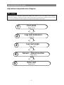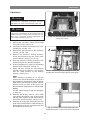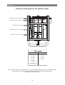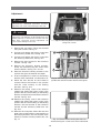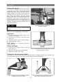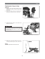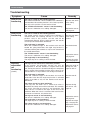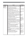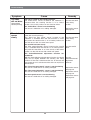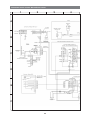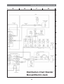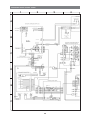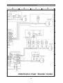
1
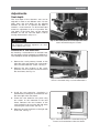
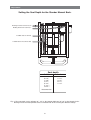
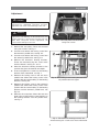
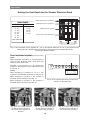
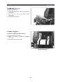
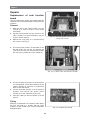
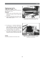
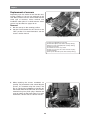
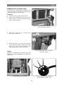
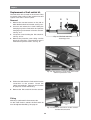
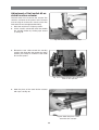
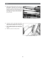
SERVICE MANUAL US Stander Seat Assembly for Permobil Power Wheelchair How to contact Permobil Permobil Inc. USA 6961 Eastgate Blvd. Lebanon, TN 37090 USA Phone: 800-736-0925 Fax: 800-231-3256 Email: [email protected] Head Office of the Permobil group Permobil AB Box 120 861 23 Timrå Sverige Tel: 060-59 59 00 Fax: 060-57 52 50 E-post: [email protected] Produced and published by Permobil AB, Sweden Edition no.2, 2005-11 Order no.: 205003-US-0 Contents Contents Introduction ........................................................................................................... Technical support................................................................................................ Spare parts ......................................................................................................... Warranties .......................................................................................................... Maintenance ....................................................................................................... 5 5 5 5 5 Adjustment dependencies diagram ..................................................................... 6 Adjustments ........................................................................................................... 7 Seat depth ......................................................................................................... 7 Half-speed adapter ........................................................................................... 14 Foot plate ......................................................................................................... 14 Leg rest angle (Manual & Electrical Back) ....................................................... 16 Leg rest angle (Combi) .................................................................................... 17 Leg rest extension ........................................................................................... 18 Sensor - Stand function ................................................................................... 18 Knee stops ....................................................................................................... Calf rest ........................................................................................................... Chest support ................................................................................................... Arm rests .......................................................................................................... Head rest .......................................................................................................... Trunk rest ......................................................................................................... Lumbar support ................................................................................................ 20 21 22 22 22 23 23 Repairs.................................................................................................................. 24 Replacement of seat function board................................................................. 24 Replacement of relay box (Combi) .................................................................. 25 Replacement of sensors ................................................................................... 26 Replacement of leg rest sensors (Combi) ....................................................... 28 Replacement of max speed sensors (Combi) .................................................. 28 Replacement of crush-protection sensors ........................................................ 30 Replacement of angle stops ............................................................................. 31 Replacement of limit switch kit ......................................................................... 32 Adjustment of limit switch kit on stand function actuator ................................. 33 Replacement of collapse protection attenuators .............................................. 35 Replacement of parallel struts .......................................................................... 35 Replacement of actuators................................................................................. 36 Replacement of knee stops strap ..................................................................... 38 Replacement of leg rest strap........................................................................... 39 Troubleshooting .................................................................................................. 40 Distribution Chart Stander Manual/Electric back ............................................. 44 Distribution Chart Stander Combi...................................................................... 46 4 Introduction Introduction The Service Manual is intended for technical personnel who maintain and repair electric wheelchairs. It is important that anyone who performs maintenance and repairs described in this manual reads and understands the content of this manual so that the work is performed professionally. Always state the chassis number when contacting Permobil to ensure that the correct information is provided. Technical Support In the event of technical problems, you should contact your dealer, or Permobil Inc. USA at 800-736-0925. Spare parts Spare parts must be ordered through your dealer. Warranties Contact your dealer or Permobil Inc. USA for information about the warranties for this chair. Maintenance See the information in the Owner’s Manual. 5 Adjustment dependencies diagram Adjustment dependencies diagram WARNING Some of the seat's settings have an affect on each other. The basic settings for the seat should be performed in the order indicated in the adjustment dependencies diagram given below. If any of the settings in the adjustment dependencies diagram are altered, then all the settings further down in the dependency diagram should be checked and, if necessary, adjusted. The other settings can be adjusted independently of each other. 1 2 3 4 5 Foot plate Page 14-15 Leg rest extension Page 18 Leg rest angle Page 16-17 Sensor - Stand function Page 18-19 Knee rest Page 20-21 6 Adjustments Adjustments Seat depth The seat depth of the Stander's seat can be adjusted in order to suit different users. For the adult seats, the seat depth can be adjusted between 18” and 22”. If a greater seat depth is needed, a seat extension can be mounted that makes an adjustment of up to 24” possible. The seat depth of the junior seats can be adjusted between 14” and 18”. The seat depth is set by moving the backrest in steps of 1”. WARNING Fig. 1. The crush-protector on the right side of the seat is mounted using two screws. To adjust the seat depth, follow the instructions carefully. Improperly performed adjustment can cause serious damage to the seat. Installation of seat extension By mounting a seat extension on the adult seat, the seat depth can be increased by an additional 2”. The seat depth can then be adjusted from 18” to 24”. 1. Remove the crush protector located on the right side of the seat frame. The crush protection is mounted with two screws, see Fig. 1. 2. Remove the rear fastener of the crushprotection sensor, mounted on the left side of the seat frame, see Fig. 2-3. Fig. 2. The rear fastener of the crush-protection sensor is mounted using a screw underneath it. 3. Install the seat extension. Installation is performed by inserting the seat extension into the rear edge of the seat frame. 4. Fasten the seat extension into place using two screws on the underside of the seat frame. Remount the rear fastener of the crush-protection sensor on the left side of the seat using the same screw, see Fig. 3. 5. Remount the crush-protector on the right side of the seat, see Fig. 1. Fig. 3. The seat extension is mounted using two screws on the underside of the seat frame. 7 Adjustments Setting the Seat Depth for the Stander Manual Back. Bearing bracket for backrest, R Bearing bracket for backrest, L Parallel strut for armrest Parallel strut for backrest slant Seat depth Adult A: B: C: D: E: F: G: 18”. 19”. 20”. 21”. 22”. 23”. * 24”. * Junior 1: 2: A: B: C: 14”. 15”. 16”. 17”. 18”. *Seat extension Fig. 4. The seat depth can be adjusted 18” - 24” on the Stander Adult and 14”-18” on the Stander Junior. Bearing bracket and both parallel struts are marked with decals showing the different settings. 8 Adjustments Adjustment WARNING Adjustments to the seat depth should only be performed by authorized personnel. Incorrect adjustment can cause serious damage to the seat. WARNING Follow the instructions carefully when making adjustments. The markings for the parallel struts, the bearing brackets for the backrest and the rear seat plate must correspond. Incorrect adjustment can cause serious damage to the seat. Fig. 5. The seat plates are mounted using four screws. 1. Remove the seat plates. These are mounted using four screws, see Fig. 5. 2. Unscrew and remove the locking screw from the backrest's parallel strut, see Fig. 6:2. 1 3. Unscrew and remove the locking screw from the armrest's parallel strut, see Fig. 6:3. 4. Remove the backrest's bearing brackets. These are mounted using two screws each from the bottom, see Fig. 6:1 and 7. 3 5. Move the backrest's bearing brackets to the position that gives the desired seat depth. 2 6. Insert and tighten the screws for the bearing brackets from underneath, see Fig. 7. 7. Remount the locking screw in the arm rest's parallel strut. Mount the locking screw in the position with the same marking as the bearing brackets, see Fig. 6:3. Fig. 6. The marking for the bearing brackets and the parallel strut must agree 8. Remount the locking screw in the backrest's parallel strut. Mount the locking screw in the position with the same marking as the bearing brackets and the armrest's parallel strut, see Fig. 6:2. 9. Remount the seat plates. Mount the rear seat plate in the position with the same marking as the bearing brackets and the parallel strut, see Fig. 5. Fig. 7. The backrest's bearing brackets are mounted using two screws each from underneath. 9 Adjustments Setting the Seat Depth for the Stander Electrical Back Bearing bracket for backrest, R Seat depth Adult Junior A: B: C: D: E: F: G: 1: 2: A: B: C: 18”. 19”. 20”. 21”. 22”. 23”. * 24”. * 14”. 15”. 16”. 17”. 18”. Bearing bracket for backrest, L Parallel strut for armrest The backrest actuator bracket *Seat extension Fig. 8. The seat depth can be adjusted 18” - 24” on the Stander Adult and 14”-18” on the Stander Junior. Bearing bracket, parallell strut and backrest actuator bracket are marked with decals showing the different settings. Front actuator bracket (Back rest actuator) Adult When mounting in positions A - D, the bracket is sawn off two fastening holes away from the fastening point being used. Example: If the bracket is to be mounted in position C, the bracket is sawn off between E and F, see Fig. 9. A B C D E F G Junior When mounting in positions A,, B or C, the actuator is mounted with its bracket as per Fig. 10. When mounting in position 1, the actuator is mounted with its bracket as per Fig. 11. Fig. 9. Front actuator bracket for the backrest actuator on the adult seat. When mounting in position 2, the actuator is mounted with its bracket as per Fig. 12. Fig. 10. Front actuator bracket for the backrest actuator on the Junior seat, positions A, B and C. Fig. 11. Front actuator bracket for the backrest actuator on the Junior seat, position 1. 10 Fig. 12. Front actuator bracket for the backrest actuator on the Junior seat, position 2. Adjustments Adjustment WARNING Adjustments to the seat depth should only be performed by authorized personnel. Incorrect adjustment can cause serious damage to the seat. WARNING Follow the instructions carefully when making adjustments. The markings for the parallel struts, the bearing brackets for the backrest and the rear seat plate must correspond. Incorrect adjustment can cause serious damage to the seat. Fig. 13. The seat plates are mounted using four screws. 1. Remove the seat plates. These are mounted using four screws, see Fig. 13. 2. Unscrew and remove the locking screw in the parallel strut, see Fig. 14:2. 1 3. Remove the front bracket for the backrest's actuator, see Fig. 14:3. 4. Remove the backrest's bearing brackets. These are mounted using two screws each from the bottom, see Fig. 14:1 and 15. 5. Move the backrest's bearing brackets to the position that gives the desired seat depth. 2 6. Insert and tighten the screws for the bearing brackets from underneath, see Fig. 15. 3 7. Mount the front bracket for the backrest's actuator. Mount the bracket in the position with the same marking as the bearing brackets, see Fig. 14:3. Fig. 14. The marking for the bearing brackets, the parallel strut and the actuator bracket must agree. Adult When mounting in positions A - D, saw the bracket off as per the description on page 10. If the bracket has already been sawn off and the depth of the seat must be increased, then the bracket can be too short. In this case a new bracket must be ordered. Part no: 310191-28-0. Junior Use the correct bracket as per the description on page 10. 8. Remount the locking screw in the parallel strut. Mount the locking screw in the position with the same marking as the bearing brackets and the actuator bracket, see Fig. 14:2. 9. Remount the seat plates. Mount the rear seat plate in the position with the same marking as the bearing brackets, the actuator bracket and the parallel strut, see Fig. 13. Fig. 15. The backrest's bearing brackets are mounted using two screws each from underneath. 11 Adjustments Setting the Seat Depth for the Stander Combi Bearing bracket for backrest, R Bearing bracket for backrest, L Parallel strut for armrest Parallel strut for backrest slant The backrest actuator bracket Seat depth Adult Junior A: B: C: D: E: F: G: 1: 2: A: B: C: 18”. 19”. 20”. 21”. 22”. 23”. * 24”. * 14”. 15”. 16”. 17”. 18”. *Seat extension Fig. 16. The seat depth can be adjusted 18” - 24” on the Stander Adult and 14”-18” on the Stander Junior. Bearing bracket, parallel struts and backrest actuator bracket are marked with decals showing the different settings. 12 Adjustments Adjustment WARNING Adjustments to the seat depth should only be performed by authorized personnel. Incorrect adjustment can cause serious damage to the seat. WARNING Follow the instructions carefully when making adjustments. The markings for the parallel struts, the bearing brackets for the backrest and the rear seat plate must correspond. Incorrect adjustment can cause serious damage to the seat. Fig.17. The seat plates are mounted using four screws. 1. Remove the seat plates. These are mounted using four screws, see Fig. 17. 1 1 2. Unscrew and remove the locking screw from the backrest's parallel strut, see Fig. 18:2. 3. Unscrew and remove the locking screw from the armrest's parallel strut, see Fig. 18:3. 4. Remove the front bracket for the backrest's actuator, see Fig. 18:4. 2 3 5. Remove the backrest's bearing brackets. These are mounted using two screws each from the bottom, see Fig. 18:1 and 19. 4 6. Move the backrest's bearing brackets to the position that gives the desired seat depth. 7. Insert and tighten the screws for the bearing brackets from underneath, see illustration 19. Fig.18. The marking for the bearing brackets, the parallel strut and the actuator bracket must agree. 8. Mount the front bracket for the backrest's actuator. Mount the bracket in the position with the same marking as the bearing brackets, see Fig. 18:4. 9. Remount the locking screw in the armrest's parallel strut. Mount the locking screw in the position with the same marking as the bearing brackets and the front bracket of the backrest's actuator, see Fig. 18:3. 10. Remount the locking screw in the backrest's parallel strut. Mount the locking screw in the position with the same marking as the bearing brackets, the front bracket of the backrest's actuator and the armrest's parallel strut, see Fig. 18:2. 11. Remount the seat plates. Mount the rear seat plate in the position with the same marking as the bearing brackets, the front bracket of the backrest's actuator and the parallel strut, see Fig. 17. Fig. 19. The backrest's bearing brackets are mounted using two screws each from underneath. 13 Adjustments Halfspeed adapter(Seat with stand-up driving) If the seat is equipped with stand-up driving functionality, then it has a half-speed adapter which provides improved driving characteristics in certain situations. In normal cases, the seat lift is engaged at half max speed as soon as the seat is being raised. The Stander seat with stand-up driving functionality has a supporting frame with a wheel that in certain cases can get in the way. The half-speed adapter allows the seat lift (the support wheel) to be run up a bit as needed when, for example, negotiating obstacles without the max speed being lowered. Fig. 20. The sensor cam for the half-speed adapter. NOTE We recommend that the seat lift be in its lowest position during normal driving in order to achieve adequate stability. The sensor cam must always sit at the highest position on the positioning plate, see Fig. 20. Adjustment 1. Run the seat lift up in order to gain access more easily from below. 2. Loosen the two screws of the sensor cam, see Fig. 20. 3. Adjust the sensor cam to its highest position. 4. Tighten the screws again. Foot plate(See the adjustment dependencies diagram on page 6) Setting the Height 1. Loosen the two locking screws on the foot plate, see Fig. 21. 2. Adjust the foot plate to the desired height. 3. Tighten the locking screws again. Fig. 21. The height setting of the leg rest is locked using two locking screws. Turning over the foot plate's holder. In the event of a need to adjust the height of the foot plate to an additional extent, the capability exists to turn the holder over which then allows the foot plate to be raised still further Fig. 23. Support wheel attachment on seats without stand-up driving functionality. Fig. 22. Support wheel attachment on seats equipped for stand-up driving. 14 Adjustments 1. Unscrew and remove the support wheels. On seats equipped for stand-up driving, they are mounted using two screws on each side of the leg rest, see Fig. 22. On seats without stand-up driving, they are mounted on the rear edge of the foot plate, see Fig. 23. 1 2. Unscrew and remove the knee rest. It is mounted with a screw, see Fig. 24:1. 3. Unscrew and remove the six screws holding the foot plate, see Fig. 24:2. 2 Fig. 24. Fastening screws for the knee rest and foot plate. 4. Unscrew and remove the calf rest's bracket. It is mounted using two screws on the back side of the leg rest, see Fig. 25. 5. Loosen the two locking screws on the foot plate, see Fig. 21. 6. Remove, turn the bracket upside down and remount in reverse order. Fig. 25. The calf rest is mounted with two screws. Setting the Angle The angle of the foot plate can be adjusted by screwing the nuts on the foot plate's adjustment screws in or out, see Fig. 26. NOTE After making an adjustment, always be sure to tighten the two locking nuts for the slope adjustment, in order to lock the setting. Fig. 26. Setting the angle of the foot plate. 15 Adjustments Leg rest angle (Manual & Electrical Back) See the adjustment dependencies diagram on page 6. The leg rest's angle can be adjusted to suit all users. 1. Loosen the screw located on the leg rest's strut. The strut is found under the seat, inside the stand function's actuator on the seat's left side, see Fig. 27. 2. Set the leg rest to the desired angle. 3. Tighten the screw again. Fig. 27. Setting the slope of the leg rest. 4. Loosen the two screws holding the locking jamb to the leg rest's belt. The locking jamb is located behind the leg rest under the middle of the seat, see Fig. 28-29. 5. With the seat in the sitting position, push the leg rest up to its highest position, slide it along the belt. NOTE The leg rest must be pushed up to its uppermost position. Any other position might lead to damage to the seat or injury to the users. 6. Tighten the belt's locking jamb again.. Fig. 28. The lock for the leg rest's belt is located on the rear of the leg rest. 7. Carefully test out all the functions of the seat. Check that the leg rest's angle feels comfortable in all positions. Fig. 29. Readjustment of the leg rest's belt. 16 Adjustments Leg rest angle (Combi) Seats equipped for stand-up driving. The slope of the leg rest can´t be adjusted Seats not equipped for stand-up driving. The leg rest's angle can be adjusted to suit all users. 1. With the seat lift in its lowest position and the seat in the sitting position, angle the leg rest in to the maximum using the adjust back/legs function on the button box. Fig. 30. On wheelchars equipped for stand-up driving, the slope of the leg rest can´t be adjusted. 2. Loosen the nut locking the cam curve, see Fig. 31. 3. Adjust the angle of the cam curve. In order to have the leg rest angled further inwards, angle the cam curve further outwards. In order to have the leg rest angled further outwards, angle the cam curve further inwards, see Fig. 32. 4. Lock the cam curve by tightening the nut again, see Fig. 31. NOTE The setting of the cam curve is very sensitive, and it is often necessary to use a trial and error method, changing the setting a number of times, in order to arrive at a satisfactory position. Fig. 31. The nut locks the angle of the cam disk. 5. Loosen the two screws holding the locking jamb to the leg rest's belt. The locking jamb is located behind the leg rest under the middle of the seat, see Fig. 28-29. 6. With the seat in the sitting position and the leg rest run in to its maximum extent using the adjust back/legs function on the button box, push the leg rest up to its highest position and slide it along the belt. NOTE The leg rest must be pushed up to its uppermost position. Any other position might lead to damage to the seat or injury to the users. 7. Tighten the belt's locking jamb again. Fig. 32. Adjust the angle of the cam disk. 8. Carefully test out all the functions of the seat. Check that the leg rest's angle feels comfortable in all positions. 17 Adjustments Leg rest extension See the adjustment dependencies diagram on page 6. When the seat is raised from the sitting to the standing position, the leg rest becomes longer in order to improve the comfort of the user. The leg rest's extension can be set to three different positions. It is set by moving the roller over which the leg rest's strap runs. The roller is mounted under the seat, behind the leg rest, see Fig. 33. 1. Unscrew and remove the screw holding the roller, see Fig. 33. 2. Loosen the two screws holding the locking jamb to the leg rest's belt. The locking jamb is located behind the leg rest under the middle of the seat, see Fig. 34. 3. Move the roller to the desired position. In order to increase the extension of the leg rest, move the roller downwards. In order to decrease the extension of the leg rest, move the roller upwards. 4. Insert and screw back in the screw holding the roller, see Fig. 33. 5. With the seat in the sitting position, push the leg rest up to its highest position, slide it along the belt. Fig. 33. The extension of the leg rest is adjusted by moving the roller. NOTE The leg rest must be pushed up to its uppermost position. Any other position might lead to damage to the seat or injury to the users. 6. Tighten the belt's locking jamb again. Fig. 34. The lock for the leg rest's belt is located on the rear of the leg rest. Sensor - Stand function See the adjustment dependencies diagram on page 6. It is very important that the limit position breaker on the seat lift be adjusted so that the wheel under the foot plate hits the floor at the correct angle using the stand function. WARNING Incorrect adjustment can cause an increased risk of tipping as well as damage to the leg rest. Note that all adjustments must be performed on a level substrate. In order to obtain a good result, the user should sit/stand in the chair while the adjustment is being performed. 1. Adjust the foot plate in the sitting position so that it is suitable for the user according to the instructions on pages 14-15. Fig. 35. For chairs without stand-up driving, the supporting frame can be adjusted once the two screws have been loosened. For chairs equipped for stand-up driving, go directly to point 3. 18 Adjustments 2. Adjust the supporting frame under the foot plate as close to the foot plate as possible, but make sure that the support wheel can rotate freely. Loosen the two screws, adjust the supporting frame to a suitable height and then tighten the two screws again, see Fig. 35. 3. Raise the seat up to an angle of 65°. On the right side, under the front part of the seat frame, there is a decal with a marking that points to the edge of the parallel strut's bracket when the seat is at a 65° angle, see Fig. 36. 4. With the seat raised to a 65° angle, the support wheel must just make contact with the floor. If not: 4a. Measure the distance between the floor and the bottom of the support wheel, see Fig. 37. 4b. Loosen the two screws on the sensor cam of the stand function, see Fig. 38. 4c. Adjust the sensor cam. If the support wheel does not touch the floor at the 65° angle, the sensor cam must be moved a corresponding length upwards in the track from the existing position. If the wheel touches the floor before the 65° angle, then the sensor cam must be adjusted downwards. Tighten the two screws. For seats without stand-up driving functionality, it can be the case that the adjustment method via the sensor cam is not sufficient, hence the remaining adjustment must be performed with the support wheel. This can be the case if the user has short legs. With the seat at a 65° angle, adjust the support wheel down towards the floor. Adjustment is performed by loosening the two screws, adjusting the supporting frame to a suitable height and then tightening the two screws again, see Fig. 39. 5. Run the seat down to the sitting position and then run the seat lift to its lowest position. 6. Raise the seat back up again to an angle of 65°. 7. Check that the support wheel touches the floor at a 65° angle when using the stand function. 65° Fig. 36. The support wheel must be touching the floor when the seat is raised to an angle of 65°. Fig. 37. Measure the distance between the support wheel and the floor. Fig. 39. For chairs without stand-up driving, the supporting frame can be adjusted once the two screws have been loosened. Fig. 38. The sensor cam of the stand function is mounted using two screws. 19 Adjustments Knee stops See the adjustment dependencies diagram on page 6. Setting the angle of the knee stops strap The knee stops strap is adjusted in order for the knee stops to have as even a layout as possible during the use of the stand function. The roller is adjusted so that the angle of the strap to the horizontal plane is equally as large downwards in the sitting position as it is upwards in the standing position, see Fig. 40-41. 1. Check and visually compare the angle of the strap to the horizontal plane in the standing and sitting positions. Fig. 40. Angle of the knee stops strap in the sitting position. Fig. 41. Angle of the knee stops strap in the standing position. 2. If the angle of the strap needs to be adjusted, remove the roller's bracket by unscrewing and removing the four screws, see Fig. 42. 3. The roller's bracket can be moved in 5 steps of 20 mm intervals. If the angle of the strap is too large in the sitting position, then move the roller up. If the angle of the strap is too large in the standing position, then move the roller down. 4. Mount the roller's bracket in a suitable position and screw the four screws back in, see Fig. 42. 5. Check and visually compare the angle of the strap to the horizontal plane in the standing and sitting positions. Fig. 42. The roller is mounted with four screws and can be moved in 5 steps of 20 mm intervals. 20 Adjustments Setting the layout 1. Adjust the knee stops for the sitting position to a location approx. 1.5 ” in front of the leg. The adjustment is made by using the knob located on the rear edge of the seat's frame, see Fig. 43. 2. Carefully test out all the functions of the seat, check that the knee stops layout feels comfortable in all positions. Fig. 43. Setting the layout of the knee stops. Setting the height 1. Loosen the knee stops locking knob, see Fig. 44:2. 2. Move the traversing positioning screw on the leg rest to an appropriate position, see Fig. 44:1. 3. Tighten the knee stops locking knob. 2 NOTE The knee stops must always bear against the positioning screw when locking is performed with the locking knob. 1 4. Carefully test out all the functions of the seat, check that the knee stops height feels comfortable in all positions. Calf rest Fig. 44. Setting the height of the knee stops. (Accessories) Setting the Height 1 2 1. Loosen the two screws on the back side of the calf rest, see illustration 45:1. 2. Set to the desired height. 3. Tighten the screws again. Adjusting forwards/backwards 1. Loosen the screw on the back side of the calf rest, see illustration 45:2. 2. Set the calf rest to the desired position. 3. Tighten the screws again. Fig. 45. Adjusting the calf rest, viewed from behind. 21 Adjustments Chest support Depth adjustment 1. Unscrew and remove the two nuts on the inner side of the arm rest, see Fig. 46:1. 1 2. Move the chest support holder so that the chest support lines up at the appropriate depth. The depth can be adjusted in this manner in steps of 1”. 2 3 3. Screw the holder firmly back in with the two nuts. Height adjustment 1. Loosen the socket head cap screws for the locking ring on each side of the chest support, see Fig. 46:2. Fig. 46. Chest support adjustment. 2. Adjust the chest support to the appropriate height. Never adjust the height so high that the chest support bar becomes invisible below the bushing, see Fig. 46:3. 3. Tighten the locking ring's socket head cap screws again. WARNING Make sure that both ends of the chest support bar are visible below the edge of the bushing after adjusting. Arm rests 1. Loosen the two nuts on the inner side of the arm rest, see Fig. 47. 2. Adjust the height and slope of the arm rest. Fig. 47. Arm rest adjustment. 3. Tighten the two nuts again. Head rest (Accessory) Height adjustment 1. Loosen the knob on the back of the back rest, see Fig. 48:1. 2. Adjust the height of the head rest as required. 3. Tighten the knob. Forward/backward adjustment 1 1. Loosen the knob on the back of the back rest, see Fig. 48:2. 2. Adjust the head rest forwards/ backwards as required. 2 3. Tighten the knob. Fig. 48. Adjusting the head rest. 22 Adjustments Trunk rest (Accessory) Height adjustment 1. Loosen the knob on the back of the back rest, see Fig. 49. 2. Adjust the trunk rest to the desired height, see Fig. 49. 3. Tighten the knob again. Fig. 49. Trunk rest adjustment. Lumbar support Vertical and depth adjustments 1. Remove the back cushion. 2. Adjust the lumbar support as required, see Fig. 50. 3. Mount the back cushion again. Fig. 50. Trunk rest and lumbar support adjustment. 23 Repairs Repairs Replacement of seat function board The two seat function boards are located under the seat plate. The seat function boards control the seat's actuators. Removal 1. With the seat in the sitting position, run the seat lift up in order to access it more easily from below. 2. Set the Circuit breaker for the chassis to the ”OFF” position. For more information, see the chassis service manual. 3. Remove the seat plate. It is mounted using four screws, see Fig. 51. Fig. 51. The seat plates are mounted using four screws. 4. The seat function boards are mounted on the left side of the seat, see Fig. 52. Remove the cover from the case the seat function boards are sitting in by pulling the cover straight up. Fig. 52. Location of the seat function boards. 5. Loosen all cable connections to the board that is to be replaced. Check the placement of the cables carefully for purposes of remounting them on the new board. 6. Loosen the board from the case by pressing upwards and inwards the plastic points sticking out on the underside of the case. 7. Place the cabling on the new board as for the old one. Fitting Mounting is performed in the reverse order. Mount the rear seat plate in a position with the same marking as the parallel strut and the backrest's bearing brackets. Fig. 53. Seat function board. 24 Repairs Replacement of the relay box Combi (Combi) A relay box is located underneath the seat.It governs the stand function cycle. Removal 1. With the seat in the sitting position, run the seat lift up in order to access it more easily from below. 2. Set the Circuit breaker for the chassis to the ”OFF” position. For more information, see the chassis service manual. Fig. 54. The combi relay box is located underneath the seat function board's case. 3. The relay box is mounted underneath the case belonging to the rear seat function board, see Fig. 54. Removal is performed by pressing together the plastic clip fixings that are sticking out of the underside of the seat function board's case, see Fig. 55. 4. Loosen all the cable connections of the relay box. Check the placement of the cables carefully for purposes of remounting them later. Fig. 55. The relay box is mounted with two ”plastic clip fixings”. The relay box is shown from below in the picture. Fitting Mounting is performed in the reverse order. 25 Repairs Replacement of sensors Depending upon the model of the Stander seat, varying numbers of sensors are mounted on the seat. Many of these sensors are mounted with the same type of brackets, hence removal and installation takes place in a similar manner. Other sensors are described on pages 28-32. 6 1 2 4 5 3 Removal 1. Run the seat up to the standing position. 2. Set the Circuit breaker for the chassis to the ”OFF” position. For more information, see the chassis service manual. 8 7 Fig. 56. Sensors 1. 2. 3. 4. 5. 6. 7. 8. Inhibit seat tilt(All)/Recline (Combi) Inhibit drive (Only seats without stand-up driving) Extra low max speed (Only with stand-up driving) Inhibit seat elevator Stand function-down stop switch. Safety stop (Protects the seat's mechanical parts) Inhibit standing Max speed allowable (Seats with stand-up driving) 3. When replacing the sensors numbered 1-5 (see Fig. 56), remove the cover surrounding the sensors. It is mounted using four screws, see Fig. 57. The sensors numbered 7-8 (see Fig. 56) are located under the seat lift cover. The cover is mounted using four plastic plugs. Remove the cover by taking out the plastic plugs. For more information, see the chassis service manual. Fig. 57. The cover is mounted using four screws. 26 Repairs 4. Remove the sensor by loosening its retaining nuts, see Fig. 58. Fig. 58. The sensor is mounted with a nut. 5. Loosen the cable connections, see Fig. 59. Check the placement of the cables for purposes of remounting later. Fig. 59. The sensors cable connection. Fitting Mounting is performed in the reverse order. Sensors 1-4 (see Fig. 56) are mounted at a height of 29 mm from the frame side member, see Fig. 60. Sensor number 5 (see Fig. 56) is mounted at a height of 26 mm from the frame side member, see Fig. 60. Other sensors are mounted so that they protrude as far as possible. 3 mm. 26 mm. Fig. 60. The sensor for the Stand-down stop switch is mounted 3 mm under the other sensors. 27 Repairs Replacement of leg rest and max speed sensors. (Combi) The leg rest sensor and the max speed sensor are mounted in the front edge of the seat, see Fig. 61. The leg rest sensor controls the angle of the leg rest. The max speed sensor cuts the maximum speed in half when the backrest is tilted more than 45° to the rear. Fig. 61. The leg rest sensor and the max speed sensor are mounted in the front edge of the seat. 1. Set the Circuit breaker for the chassis to the ”OFF” position. For more information, see the chassis service manual. 2. Remove the seat plates. These are mounted using four screws, see Fig. 62. Fig. 62. The seat plates are mounted using four screws. 3. Remove the plate that the sensor is mounted on. It is mounted with two screws, see Fig. 63. Fig. 63 The plate with the sensors is mounted with two screws. 28 Repairs 4. Remove the sensor by loosening its two retaining screws, see Fig. 64. 5. The max speed sensor is connected to the seat function board. The leg rest sensor is connected to the relay box. Follow the cabling to the seat function board or relay box and cut the wiring bundle tie holding the cabling together. Take note of the location of the wiring bundle tie for purposes of later remounting. See Figs. 65 and 66. A B Fig. 64. The max speed sensor (A) and the leg rest sensor (B) are mounted on the plate using two screws each. Fitting Mounting is performed in the reverse order. Mount the rear seat plate in a position with the same marking as the parallel strut and the backrest's bearing brackets. Fig. 65. The relay box viewed from underneath the seat. Fig. 66. The seat function board. 29 Repairs Replacement of crush-protection sensor A crush-protection sensor is located on the left side of the seat. When the stand function is being used, the sensor stops the seat being lowered from the standing to the sitting position when something becomes caught in the mechanism. Removal 1. Run the seat up to the standing position. 2. Set the Circuit breaker for the chassis to the ”OFF” position. For more information, see the chassis service manual. Fig. 67. The crush-protection sensor is mounted on the left side of the seat frame. 3. Remove the sensor. It is mounted using two screws, see fig. 68. 4. Follow the cable to the standing actuator. Cut the wiring bundle tie holding the cable. Take note of the cable's routing and attachment for purposes of later remounting. See Figs 69 and 70 Fitting Mounting is performed in the reverse order. Fig. 68. The crush-protection sensor is mounted with two screws. Fig. 69. The electrical connections are located behind a protective cover. Fig. 70. The actuator's electrical connections. 30 Repairs Replacement of angle stop An angle stop is mounted on the backrest. The angle stop causes the backrest to never be able to be angled down at more than 90°. Removal 1. Run the seat up to the standing position. 2. Set the Circuit breaker for the chassis to the ”OFF” position. For more information, see the chassis service manual. Fig. 71. The angle stop is mounted on the back side of the backrest. 3. Remove the angle stop. It is mounted using two screws, see Fig. 72. 4. Follow the cable to the seat function board. Cut the wiring bundle tie holding the cable. Take note of the cable's connection and routing for purposes of later remounting. Fig. 72. The angle stop is mounted using two screws. Fitting Mounting is performed in the reverse order. The angle stop is always mounted with an angle of 90°, see Fig. 74. 90° 30 ° ° 60 Fig. 73. Seat function board. Fig. 74. The angle stop must be mounted with an angle of 90° 31 Repairs Replacement of limit switch kit. The limit switch kit is located on the actuator. They are aware of the position of the actuator and send signals to the seat's control system. 1 Removal 2 3 1. Remove the actuator bracket on the side on which the limit switch kit is located, see Fig. 75:1. 2. Unscrew and remove the screw holding the clamping ring for the limit switch kit. Open the clamping ring and remove it from the actuator, see Fig. 75:1. 3. Loosen the screws holding the limit switch kit, see Fig. 75:2-3. Fig. 75. The limit switch kit fastening points. 4. Remove the protective cover sitting over the electrical connections. The protective cover is mounted using three screws, see Fig. 76. Fig. 76. The electrical connections are located behind a protective cover. 5. Follow the cable from the limit switch kit to the connections to the actuator. Loosen the cable's two terminals. Take note of its location for purposes of later remounting. 6. Remove the limit switch kit from the actuator. Fitting Mounting is performed in the reverse order. On the stand function actuator, the limit switch kit must be adjusted after fitting, see page 33. Fig. 77. Electrical connections for the actuator and the limit switch kit. 32 Repairs Adjustment of limit switch kit on stand function actuator The limit switch kit is located on the actuator. The switches are aware of the position of the actuator and send signals to the seat’s control system. The limit switch kit must be adjusted after fitting 1. Raise the seat lift to it’s highest position. 2. On the seat lift, activate the switch that inhibits the standing function by winding tape around it, see fig.78. Fig. 78. Activate the switch with tape. 3. Elevate the seat a little towards the standing position, then lower the seat towards the sitting position just enough to make the seat frame rest on the spacers. Fig. 79. In sitting position, the seat frame rests on two spacers. 4. Mark the piston of the stand function actuator with a pen, see Fig. 80. Fig. 80. Mark the piston of the stand function actuator. 33 Repairs 5. Remove the rubber protection that covers the limit switch kit. Loosen the screw on the lower end position switch (Fig. 81:1) and adjust the switch so that the stand function actuator extends a further 2 mm. This adjustment must be sufficient to keep the frame prestressed. Then tighten the screw to lock the switch in the new position. 1 2 Fig. 81. Lower and upper end position switches. 6. Loosen the screw on the upper end position switch (Fig. 81:2). Adjust the position of the switch untill the raising stops at 75°, see fig. 82. 7. Refit the rubber protection on the limit switch kit and remove the tape from the switch on the seat lift. 8. Lower the seat lift to its lowest position. Fig. 82. Raising must stop at 75°. 34 Repairs Replacement of collapse protection attenuators A collapse protection attenuator is mounted in parallel with the actuator for stand function. If the actuator breaks down with the seat in the standing position, then the collapse protection attenuator ensures that the seat will safely and slowly return down to the sitting position. Removal 1. With the seat in the sitting position, run the seat lift up in order to access it more easily from below. 2. Remove the collapse protection attenuator by loosening its two retaining screws, see Fig. 83. Fig. 83. Lower and upper end position switches. Fitting Mounting is performed in the reverse order. Replacement of parallel struts Depending upon the model of the seat, the number of parallel struts can vary. All parallel struts are however mounted in the same manner, using two screws, see Fig. 84. WARNING Always observe extreme caution when removing a parallel strut since it can involve heavy parts of the seat becoming unstable and needing support in another manner. Fig. 84. The parallel strut is mounted with two screws, the parallel strut for the back/legs is shown in the picture. 1. With the seat in the sitting position, run the seat lift up in order to access it more easily from below. 2. Remove the parallel strut by loosening its two retaining screws. Fitting 1. When replacing a parallel strut for an arm rest or back rest, check that the marking is in accordance with the other settings, see ”Setting the seat depth” on pages 7-13. 2. Mount the parallel strut using its two retaining screws. 35 Repairs Replacement of actuators Depending upon the model of the Stander's seat, the number of actuators can vary. Removal 1. With the seat in the sitting position, run the seat lift up in order to access it more easily from below. 2. Set the Circuit breaker for the chassis to the ”OFF” position. For more information, see the chassis service manual. 3. Remove the seat plate in order to access the seat function board. The seat plate is mounted using four screws, see Fig. 85. Fig. 85. The seat plates are mounted using four screws. 4. Remove the protective cover sitting above the actuator's electrical connections. The protective cover is mounted using three screws, see Fig. 86. Fig. 86. The electrical connections are located behind a protective cover. 5. Loosen the two terminals from the actuator, see Fig. 87. Take note of its location for purposes of later remounting. Fig. 87. The actuator's electrical connections. 36 Repairs 6. Remove the actuator by loosening its two fasteners. The fastening points consist of screws and nuts, see Fig. 88-90. When removing the stand function actuator, the collapse protection attenuator must also be removed, see page 35. 7. Remove the limit switch kit, see page 32. WARNING Always observe extreme caution when removing an actuator since it can involve heavy parts of the seat becoming unstable and needing support in another manner. Fig. 88. The stand function actuator is mounted with two screws. Fitting Mounting is performed in the reverse order. Mount the rear seat plate in a position with the same marking as the parallel strut and the backrest's bearing brackets. Fig. 89. The actuator for back/leg adjustment is mounted using two screws. Fig. 90. The seat tilt actuator is mounted using two screws. 37 Repairs Replacement of knee stops strap Removal 1. With the seat in the sitting position, run the seat lift up in order to access it more easily from below. 2. Remove the seat plate. It is mounted using four screws, see Fig. 91. 3. Remove the cover that surrounds the inhibit switches. The cover is mounted with four screws, see Fig. 92. NOTE Fig. 91. The seat plates are mounted using four screws. Before removing, check how the strap is mounted for purposes of remounting it later. 4. Remove the strap lock, see Fig. 93:1 5. Remove the screw that holds the strap at the knee stops, see Fig. 93:3. Fitting The knee stops strap has an eye at each end as well as an eye a small distance in from one of the ends. The strap must be mounted so that the eye that is located a small distance in from the end is ultimately situated under the seat with the eye turned upwards. 1. Screw the strap in firmly at the knee stops, see Fig. 93:3. 2. Pull the strap under the roller (93:2), up over the leg rest and straight into the clamp. 3. Thread the strap through the clamp from below. 4. Mount the strap together with the strap lock, see Fig. 93:1. Fig. 92. The cover is mounted using four screws. NOTE 1 Check that the strap is not twisted or damaged. 2 .5. Remount the covers and seat plates. See Figs. 92 and 91. 6. The rear seat plate is mounted in a position with the same marking as the parallel strut and the backrest's bearing brackets. Fig. 93. Mounting of knee stops strap. 38 3 Repairs Replacement of leg rest strap Removal 1. With the seat in the sitting position, run the seat lift up in order to access it more easily from below. 2. Remove the knee stops by unscrewing and removing its retaining screws, see Fig. 94. Fig. 94. The knee stops retaining screw. 3. Loosen the two screws on the belt's rear bracket, see Fig. 95. WARNING Observe extreme caution when loosening the belt's rear bracket as the leg rest will become completely unconstrained. Press firmly against it so that it does not fall onto the floor. Fig. 95. The leg rest strap's rear bracket. 4. Remove the strap from the leg rest by unscrewing and removing the screw, see Fig. 96. Fitting Mounting is performed in the reverse order. Fig. 96. The leg rest strap's rear bracket. 39 Troubleshooting Troubleshooting Symptom Seat lift not functioning Cause Remedy The seat is raised to the standing position. The ”Inhibit seat elevator” sensor, located on the subframe, is activated when the standing function is in its lowest position, and only in this position can the seat be raised Run the seat down to the sitting position. The ”Inhibit seat elevator” sensor is not functioning. The sensor is defective or its cabling damaged. Seat tilt not functioning The seat is raised to the standing position. The ”Inhibit seat tilt” sensor, located on the subframe, is activated when the standing function is in its lowest position. Only in this position can the seat tilt be maneuvered upwards. Due to safety reasons, the seat tilt can always be maneuvered downwards. The angle stop is activated. When the combined angle of the backrest and seat tilt exceed 90° going backwards, the angle stop function is activated, allowing the backrest to only be run forward and the seat tilt downwards. The ”Inhibit seat tilt” sensor is not functioning The sensor is defective or its cabling damaged. The angle stop is not functioning The angle stop or its cabling is short-circuited. Back/leg adjustment not functioning. (Combi) The leg rest has moved to its innermost position. In this position, the back/legs function can only be maneuvered so that the backrest is angled more to the rear. The leg rest sensor is located in the leg rest component and it is aware of the back/legs position. If this sensor is not activated then it is not possible to run the leg rest further in. The angle stop is activated. When the combined angle of the backrest and seat tile exceed 90° to the rear, the angle stop function is activated making it possible to only run the backrest and seat tilt downwards. The safety sensor has been activated. If the leg rest has been run in further than what is allowable, the safety sensor will be activated. This normally only occurs if the leg rest sensor is not functioning. The safety sensor is located to the right at the front of the subframe. When the sensor is activated, the back function cannot be run forwards, only backwards. The leg rest sensor is not functioning The sensor is defective or its cabling damaged. The angle stop is not functioning The angle stop or its cabling is short-circuited. The safety sensor is not functioning The sensor is defective or its cabling damaged. 40 Replace the sensor, see page 26. Run the seat down to the sitting position. Run the backrest up. Replace the sensor, see page 26. Replace the angle stop, see page 31. Adjust the angle of the leg rest, see pages 6 and 17. Run the seat tilt down. Replace the leg rest sensor, see page 28. Replace the sensor, see page 28. Replace the angle stop, see page 26. Replace the sensor, see page 31 Troubleshooting Symptom The stand function is not functioning. Cause Remedy Seat tilt activated. When the seat tilt is in its lowest position, a sensor is activated in the actuator's limit position casing, and only then is it possible to run the stand function. Run the seat tilt down The seat lift is not in the correct position. The ”Inhibit standing” sensor, located on the seat lift post, is activated when the seat lift is in position for the stand function to be able to be run. Run the seat lift to the correct position. The leg rest is in its innermost position. (Combi) The stand function will stop if the leg rest ends up in its innermost position. There is a sensor, located in the leg rest component, that is aware of the back/legs position and if this sensor is not activated (pressed in) then the stand function cannot be run upwards. The stand function is already in its uppermost position. A limit position casing with a sensor is located on the stand function actuator. This sensor stops the stand function in the upper position. The sensor is normally adjusted so that it is allowable to elevate oneself up to 75-80°. The crush-protection is activated. A crush-protection sensor is located on the left side of the seat frame. When this is activated, it is not possible to run the stand function downwards, only upwards. The safety sensor has been activated. If the stand function has been run up so far that the leg rest goes further in than what is allowable, then the safety sensor will be activated. This normally only occurs if the leg rest sensor is not functioning. The safety sensor is located at the front right on the subframe. When the sensor is activated the stand function can only be run downwards. The limit switch kit on the seat tilt actuator is not functioning. The limit switch kit is not functioning or its cabling defective. The ”Inhibit standing” sensor is not functioning. The sensor is not functioning or its cabling defective. The leg rest sensor is not functioning. The sensor is not functioning or its cabling defective. The limit switch kit on the stand function actuator is not functioning. The limit switch kit is not functioning or its cabling defective. The crush-protection sensor is not functioning or short-circuited. The crush-protection sensor or its cabling is short-circuited. The safety sensor is not functioning. The sensor is defective or its cabling damaged. The ”Stand down” sensor is not functioning The sensor or its cabling is short-circuited. 41 Adjust the angle of the leg rest, see page 17. Run the stand function downwards. Check whether anything has become caught in the mechanism. Replace the leg rest sensor, see page 28. Replace the kit, see page 32. Replace the sensor, see page 26. Replace the sensor, see page 28. Replace the kit, see page 32. Replace the sensor, see page 30. Replace the sensor, see page 26. Replace the sensor, see page 26. Troubleshooting Symptom Cause Remedy The chair will not drive The seat is raised to the standing position. The ”Inhibit drive” sensor, located on the subframe, is activated when the standing function is in its lowest position. Only in this position can the chair be driven. Run the seat down to the sitting position. (Seat without stand-up driving) The ”Inhibit drive” sensor is not functioning The sensor is defective or its cabling damaged. The chair moves slowly The seat is raised to the standing position (Seat with stand-up driving) The ”Extra low max speed” sensor, located on the subframe, is activated when the stand function is used. Only when the stand function is in its lowest position can the chair be run with its normal max speed. The seat lift has been run up. The ”Max speed allowable” sensor, located on the seat lift post, is activated when the seat lift is in its lower position. Only with the seat either in or in the vicinity of the lowest position can the chair be run with normal max speed. The Vertical/Horizontal adjustment function run backwards. With the Vertical/Horizontal adjustment function, the entire seat can be angled between the standing and sitting positions. If the seat is tilted more than 45° to the rear, the max speed sensor is activated and the chair can only be run at half-speed. The ”Extra low max speed” sensor is not functioning The sensor is defective or its cabling damaged. The ”Max speed allowable” sensor is not functioning The sensor is defective or its cabling damaged. The max speed sensor is not functioning The sensor is defective or its cabling damaged. 42 Replace the sensor, see page 26. Run the seat down to the sitting position. Run the seat lift down. Run the Vertical/Horizontal adjustment forwards. Replace the sensor, see page 26. Replace the sensor, see page 26. Replace the sensor, see page 28. Notes 43 Distribution Chart Stander Manual/Electric-back 1 2 3 A B C D E F 44 4 Distribution Chart Stander Manual/Electric-back 5 6 7 8 A B C D E Distribution Chart Stander Manual/Electric-back 45 F Distribution Chart Stander Combi 1 2 3 A B C D E F 46 4 Distribution Chart Stander Combi 5 6 7 8 A B C D E F Distribution Chart Stander Combi 47 Order no.: 205003-US-0