1
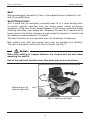
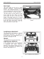
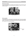
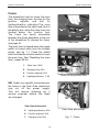
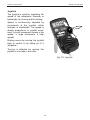
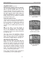
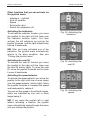
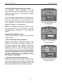
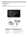
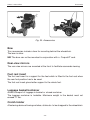
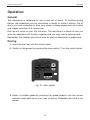
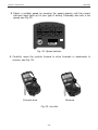
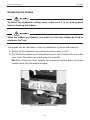
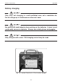
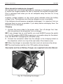
TRAX
Owner´s manual
US
How to contact Permobil
Permobil Inc. USA
6961 Eastgate Blvd.
Lebanon, TN 37090
USA
Phone: 800-736-0925
Fax:
800-231-3256
Email: [email protected]
Permobil Group Head Office
Permobil AB
Box 120, 861 23 Timrå, Sweden
Tel: +46 60 59 59 00. Fax: +46 60 57 52 50
E-mail: [email protected]
Prepared and published by Permobil AB, Sweden.
Edition 3, 2006-01
Order no. 201083-US-0
-3-
Owner´s manual Trax
Contents
Contents
General introduction . . . . . . . . . . . . . . . . . . . . . . . . . . . . . . . . . . . .6
Specially adapted wheelchairs . . . . . . . . . . . . . . . . . . . . . . . . . . 6
Safety Instructions . . . . . . . . . . . . . . . . . . . . . . . . . . . . . . . . . . . . .7
Design and function . . . . . . . . . . . . . . . . . . . . . . . . . . . . . . . . . .10
General . . . . . . . . . . . . . . . . . . . . . . . . . . . . . . . . . . . . . . . . . . .10
Chassis . . . . . . . . . . . . . . . . . . . . . . . . . . . . . . . . . . . . . . . . . . .10
Seat . . . . . . . . . . . . . . . . . . . . . . . . . . . . . . . . . . . . . . . . . . . . . 11
Seat lift . . . . . . . . . . . . . . . . . . . . . . . . . . . . . . . . . . . . . . . . . . . .11
Wheels . . . . . . . . . . . . . . . . . . . . . . . . . . . . . . . . . . . . . . . . . . . .12
Lighting/reflectors . . . . . . . . . . . . . . . . . . . . . . . . . . . . . . . . . .12
Electrical system . . . . . . . . . . . . . . . . . . . . . . . . . . . . . . . . . . .13
Control panel . . . . . . . . . . . . . . . . . . . . . . . . . . . . . . . . . . . . . . .15
Joystick menu . . . . . . . . . . . . . . . . . . . . . . . . . . . . . . . . . . . . . .20
Accessories . . . . . . . . . . . . . . . . . . . . . . . . . . . . . . . . . . . . . . . . .23
Tool wallet . . . . . . . . . . . . . . . . . . . . . . . . . . . . . . . . . . . . . . . . .23
Bow, luggage basket, crutch holder etc. . . . . . . . . . . . . . . . . . .24
Operation . . . . . . . . . . . . . . . . . . . . . . . . . . . . . . . . . . . . . . . . . . . .25
General . . . . . . . . . . . . . . . . . . . . . . . . . . . . . . . . . . . . . . . . . .25
Driving . . . . . . . . . . . . . . . . . . . . . . . . . . . . . . . . . . . . . . . . . . .25
Driving rules . . . . . . . . . . . . . . . . . . . . . . . . . . . . . . . . . . . . . . .29
Releasing the brakes . . . . . . . . . . . . . . . . . . . . . . . . . . . . . . . .32
Charging the batteries . . . . . . . . . . . . . . . . . . . . . . . . . . . . . . . 33
Transport . . . . . . . . . . . . . . . . . . . . . . . . . . . . . . . . . . . . . . . . . . . .35
Air transport . . . . . . . . . . . . . . . . . . . . . . . . . . . . . . . . . . . . . . .36
Preventive maintenance . . . . . . . . . . . . . . . . . . . . . . . . . . . . . . .37
General . . . . . . . . . . . . . . . . . . . . . . . . . . . . . . . . . . . . . . . . . . .37
Cleaning . . . . . . . . . . . . . . . . . . . . . . . . . . . . . . . . . . . . . . . . . .38
Wheels . . . . . . . . . . . . . . . . . . . . . . . . . . . . . . . . . . . . . . . . . .38
Batteries . . . . . . . . . . . . . . . . . . . . . . . . . . . . . . . . . . . . . . . . . .38
Repairs . . . . . . . . . . . . . . . . . . . . . . . . . . . . . . . . . . . . . . . . . . . . .39
Resetting the main fuse/circuit breaker . . . . . . . . . . . . . . . . . .39
Changing fuses . . . . . . . . . . . . . . . . . . . . . . . . . . . . . . . . . . . .41
Changing batteries . . . . . . . . . . . . . . . . . . . . . . . . . . . . . . . . . .42
Changing inner tubes . . . . . . . . . . . . . . . . . . . . . . . . . . . . . . . .43
Filling with air . . . . . . . . . . . . . . . . . . . . . . . . . . . . . . . . . . . . . .44
Labels . . . . . . . . . . . . . . . . . . . . . . . . . . . . . . . . . . . . . . . . . . . . . . .45
Specifications . . . . . . . . . . . . . . . . . . . . . . . . . . . . . . . . . . . . . . . .47
Electrical system . . . . . . . . . . . . . . . . . . . . . . . . . . . . . . . . . . . . . .48
-4-
Contents
Owner´s manual Trax
Contents Trax seat
General introduction . . . . . . . . . . . . . . . . . . . . . . . . . . . . . . . . . . .50
Safety Instructions . . . . . . . . . . . . . . . . . . . . . . . . . . . . . . . . . . . .50
Specially adapted product . . . . . . . . . . . . . . . . . . . . . . . . . . . . 50
Design and function . . . . . . . . . . . . . . . . . . . . . . . . . . . . . . . . . .51
General . . . . . . . . . . . . . . . . . . . . . . . . . . . . . . . . . . . . . . . . . . .51
Seat . . . . . . . . . . . . . . . . . . . . . . . . . . . . . . . . . . . . . . . . . . . . . 52
Back rest . . . . . . . . . . . . . . . . . . . . . . . . . . . . . . . . . . . . . . . . . .52
Arm rests . . . . . . . . . . . . . . . . . . . . . . . . . . . . . . . . . . . . . . . . . .52
Accessories . . . . . . . . . . . . . . . . . . . . . . . . . . . . . . . . . . . . . . . . . .52
Adjusting the settings . . . . . . . . . . . . . . . . . . . . . . . . . . . . . . . . . .53
Seat angle . . . . . . . . . . . . . . . . . . . . . . . . . . . . . . . . . . . . . . . . .53
Arm rest . . . . . . . . . . . . . . . . . . . . . . . . . . . . . . . . . . . . . . . . . . .54
Maintenance and transport . . . . . . . . . . . . . . . . . . . . . . . . . . . . . .55
Technical specifications . . . . . . . . . . . . . . . . . . . . . . . . . . . . . . . .56
Important Information
(only for the US-market)
-5-
. . . . . . . . . . . . . . .58-59
Owner´s manual Trax
General introduction
General introduction
In order to get the best possible use from your wheelchair, it is important to use
it in the intended way. We therefore advise you to carefully read the operating
instructions, especially the safety instructions. Keep the operating instructions
with the rest of the things belonging to the chair.
The first thing you should do is to charge the batteries. If you’re not sure what to
do, read the chapter on Battery charging on pages 33-34. Charging takes about
ten hours.
Specially modified wheelchairs
If your wheelchair is marked with a “Specially modified product” sticker, it has
been modified to your specific needs and wishes. This means that the design
and functions could be different from the text in these operating instructions, or
the design and functions of other wheelchairs of the same type.
The seat can also contain parts that are unique to your chair. These aren’t
available as spare parts, and must be made as required. This can affect the
repair time of your seat.
Specifcations
All information and specifications given in these operating instructions where
applicable when this wheelchair was delivered. As Permobil carries out
continual development and improvement, we reserve the right to make changes
without prior notice.
-6-
Owner´s manual Trax
Safety instructions
Safety instructions
General
A wheelchair is a motor-driven vehicle, so be very careful when using it.
Incorrect use can cause a risk of injury or damage to the chair. To reduce these
risks, you should read the operating instructions carefully, especially the safety
instructions and warnings.
Any improper modification of the wheelchair and its systems may increase the
risk of accident. Follow the recommendations in the section on Operation in
order to avoid risks when driving.
All modifications to, and interference with, the key systems of the wheelchair
should be done by qualified servicing engineers. Always contact a qualified
service engineer in case of doubt.
Warning
Wherever you see this warning symbol, take special care. There could be
a risk of personal injury.
Maximum weight of user
The wheelchair is designed for one person with a maximum weight of 298 Ibs.
If the wheelchair is fitted with a seat lift, the maximum user weight is 220 Ibs.
Passengers
It is absolutely forbidden to carry passengers on the wheelchair.
Operation
Do not let children drive the wheelchair without supervision.
Do not drive the wheelchair over any edges higher than 4,5 inches.
When driving downhill, select the slowest speed and take great care.
The wheelchair is not designed for driving down slopes with a gradient greater
than 15°.
Do not drive up slopes with a gradient greater than 15°. There is a risk that the
wheelchair will not maneuver safely.
Do not drive the wheelchair where the sideways gradient is more than 12°.
There is a risk of tipping over.
-7-
Owner´s manual Trax
Safety precautions
Opeating the seat lift
Make sure nothing gets jammed between the chassis and the seat when you are
operating the seat lift. The center of gravity is higher when the seat is raised,
increasing the risk of tipping. So use the seat lift only on flat ground and not on
uneven surfaces.
Releasing the brakes
Make sure the wheelchair is on a level surface before you release the brakes,
so it doesn’t roll away.
If the wheelchair is fitted with servo-steering, it will not be possible to steer it
electrically once the brakes are released. The wheelchair can be steered
manually by turning the front wheels directly by hand.
Charging the batteries
Charging should be done in a well-ventilated area, not in a wardrobe or closet.
You should not charge the batteries in a bathroom or wet area. Only use a
charger with a maximum charging current of 15A. You should not try to drive the
chair when the charger is connected, since this will not work.
Transport
Ensure that the chair is properly secured (see page 35). A chair that is not
properly secured can cause injury and damage if it comes loose.
-8-
Owner´s manual Trax
Safety precautions
Servicing
Only attempt the servicing and maintenance that the operating instructions say
may be done by the user. All other servicing and maintenance should be done
by someone with sufficient knowledge to be able to do it correctly.
Always disconnect the positive terminal of the battery before you work on the
electrical system of the wheelchair. Take care when using metal objects while
working on the battery. A short circuit could easily cause an explosion. Always
use protective gloves and glasses.
The recommended air pressure is 36 psi. The tire could explode if you over-inflate it.
-9-
Owner´s manual Trax
Design and Function
Design and Function
General
1
2
3
4
7
6
5
1. Seat (Trax seat)
5. Rear wheel/drive wheel
2. Control panel
6. Front wheel
3. Chassis
7. Chassis cover
4. Foot rest
Fig. 1. Electric wheelchair Trax
- 10 -
Owner´s manual Trax
Design and Function
Seat
See enclosed seat instructions (Trax) or the supplied Owner’s Manual for the
seat (CorpusII/Miniflex).
Seat lift/seat twist
Trax is fitted with an electrically controlled seat lift or a fixed seating pillar.
A position adjuster operated from the control panel allows continuous
adjustment of the seat to any height between 20-29 inches, permitting simple
matching with table, seat heights etc. Whenever the seat lift is raised from its
lowest position the chair's maximum forward speed is lowered to 4 miles/h and
the maximum reverse speed to 2,5 miles/h.
The seat lift function is only operative when the wheelchair is stationary.
Both electric seat twist and manual seat twist are possible (not Miniflex).
The seat is mounted to twist to the right or the left, see Fig. 2.
Make sure nothing is trapped between the chassis and the seat when
operating the seat lift.
Use of the seat twist function must take place only on a level surface.
Release lever for
manual seat twist
Fig. 2. Manual seat twist
- 11 -
Design and Function
Owner´s manual Trax
Seat angle
Front
The seat angle can be set in three
different positions, forward-leaning,
neutral and backward-leaning. If the
seat is equipped with seat twist, the seat
must be in neutral, i.e. level, position.
The seat angle is set by means of the
holes under the seat. There are three
holes under the seat at the front and
three at the back, see fig. 3. A level
position is obtained by mounting screws
in the equivalent row of holes front and
back. For more information, read the
user instructions for your seat.
Fig. 3. Trax seat in neutral position
(level)
Lengthways adjustment
The wheelchair has electric or manual
lengthways adjustment. The length of
the wheelchair can be adjusted by up to
8 inches, see page 18, 28.
light
Wheels
The wheelchair has pneumatic tires.
Lighting and reflectors
In the standard version, the wheelchair
is equipped with lights, direction
indicators and reflectors back and front.
For more information on lighting and
blinkers, see pages 16-17.
light
Fig. 4 Lighting and reflectors
- 12 -
Design and Function
Owner´s manual Trax
Electrical system
The wheelchair batteries are situated under the battery cover in the center of the
chassis. The batteries are maintenance-free (gel-type), so there is no need to
check fluid levels.
Fig. 5. Batteries
Drive system
The wheelchair has a drive pack for each drive wheel. The motors regulate
speed and braking and activate turning. A joystick on the control panel passes
signals to the electronic unit situated centrally under the chassis cover at the far
rear, and this in turn controls the motors.
Electric
motor
Fig. 6. Electric motor
- 13 -
Design and Function
Owner´s manual Trax
Fuses
The wheelchair has four fuses, the main
fuse, the charging fuse, the fuse for the
position adjuster and that for
lighting/direction indicators.The main
fuse is mounted at the right-hand front of
the battery box, while the other three are
located below the junction box.
The fuses are easily accessible
between the shock absorbers at the rear
of the wheelchair.To change the fuses,
see page 41.
On
Off
1
Center
Main fuse
The main fuse is tripped when the toggle
switch is turned away from the chassis
center, see fig. 7.1. Press the switch
back towards the chassis center to reset
the main fuse. See "Resetting the main
fuse", pages 39-40.
2
1.
3
4
Main fuse 100A
2. Charging fuse 20A
3. Position adjuster 15A
4. Lighting/indicators 7,5A
NB! Under very specific circumstances,
the fuses in the Safe Gate electronics
may cut off the power supply.
This will require checking by a
service engineer before the fuses
are changed.
Fuses in the junction box
5
6
7
Safe Gate electronics
5. Lighting/indicators 30A
Safe Gate electronics
6. Position adjuster 30A
Fig. 7 . Fuses
7. Charging fuse 30A
- 14 -
Owner´s manual Trax
Design and Function
Control panel
The wheelchair control panel is fixed to the right or left-hand arm rest, with
adjustable location on the panel holder for optimum ease of use. The illustration
below shows the different control panel functions.
1
2
3
4
5
8
6
7
9
10
Fig. 8. Control panel
1. Lighting
6. Horn
2. Direction Indicators
7. Speed selector (low, medium, high)
3. Seat lift
8. Joystick
4. On/off switch
9. Start key
5. Battery voltage indicator
10. Button box
- 15 -
Owner´s manual Trax
Design and Function
Start key
The start key is a plug device which is
inserted into the control panel. The key
must be inserted before the main
switch can be activated.
Fig. 9. Start key
Main switch
The main switch acts as an on/off
switch for power to the wheelchair and
must be set to "on" before the chair will
operate.
NB! First switch off the power on the
maneuvering panel (switch marked "0")
before switching the power off on the
main fuse.
+ -
Fig. 10. Main switch
Seat lift
The switch for moving the seat lift up
and down. When the seat lift is in
operation, the indicator lamp (Fig. 11)
lights. Whenever the seat lift is raised
from its lowest level, maximum speed
is reduced by half (approx. 4,5 miles/h,
7 km/h).
+ -
Fig. 11. Seat lift switch
Direction indicators
Pressing the direction indicator
symbols will activate the right or lefthand direction indicator.
A second press on the same symbol
will stop the indicators flashing.
+ -
Fig. 12. Direction indicator switch
- 16 -
Owner´s manual Trax
Design and Function
Lighting
The lights will be turned on when the
lighting symbol is pressed. A second
press will turn them off again.
Horn
Pressing this switch sounds the horn to
attract the attention of other road users.
+ -
Fig. 13. Horn switch
Battery voltage indicator
The window display on the control
panel (Fig. 14) indicates the following
(left to right):
Red/yellow/green = Fully charged
Red/yellow
= Half charged
Red
= Recharge batteries
+ -
Fig. 14. Battery voltage indicator
Speed selector
The speed can be set at three levels,
with one or more of the indicator lamps
lighting up, depending on the speed
range selected.
+ -
1 lamp lit = Low speed
2 lamps lit = Medium speed
3 lamps lit = Maximum speed
Fig. 15. Speed selector
- 17 -
Owner´s manual Trax
Design and Function
Small control box
The small control box is attached to the right or left-hand armrest behind the
control panel. The small control box contains the various options such as wheelchair
lengthways adjustment, seat twist (if equipped) and backrest angle. The pictures below
show the different functions of the small control box and its location.
Back rest angle (Corpus II only)
The backrest can be angled back to the user's desired position. Pressing the top part of
the switch causes the back to rise up. The
back can be lowered by pressing the lower
part of the switch.
Back rest slope angle can be continuously
adjusted backwards to 130°.
Lengthways adjustment
The distance between the foot rest and the
seat can be adjusted. Pressing the upper
part of the symbol causes the footrest to
move outward, while it moves back again if
the lower part is pressed. This makes it easy
to adjust the chair to the user's leg length and
allows the legs to be stretched during driving.
Extending the foot rest completely gives a
smoother ride outdoors. Retracting it makes
driving round the house more convenient.
More information on page 28.
Fig. 16. Back rest angle
Seat twist
The seat twist enables the seat to be twisted
out. This makes it easier to get on and off the
seat. When seat twist is activated, a lamp
lights above the seat lift symbol on the control panel. The wheelchair is immobilized
while this light is on. More information on
page 28. The seat can only be twisted in one
direction, to the right or to the left, depending
on how it is mounted.
Fig. 17. Lengthways adjustments
Use of the seat twist function must
take place only on a level surface.
Fig. 18 Seat twist (Optional)
- 18 -
Owner´s manual Trax
Design and Function
Joystick
The joystick is used for regulating the
speed of the wheelchair forwards or
backwards, for turning and for braking.
Speed is continuously adjusted by
movements of the joystick, either
forwards or backwards. The speed is
directly proportional to joystick movement (a small movement causes a low
speed, a large movement a high
speed).
Braking occurs by moving the joystick
back to neutral or by letting go of it
altogether.
Turning is effected by moving the
joystick to one side or the other.
Fig. 19. Joystick
- 19 -
Owner´s manual Trax
Joystick menu
Design and Function
(Leverman)
Switching the joystick menu on and off
You can choose whether you want to be
able to use the joystick menu or not. To
choose between having the joystick menu
switched on/off you hold the light button and
the right indicator button down while you
switch the wheelchair on, see Fig. 20. Three
beeps indicate that the joystick is switched
on and two that it is off.
Fig. 20. Entering joystick
menu mode
Using the joystick menu
There are two ways to go into joystick menu
mode, either by holding the light button in
for two seconds or by holding the joystick at
the extreme left or right position for two
seconds. A short audible signal confirms the
action.
NB! To be able to use the joystick to
activate the joystick menu, the electronic
unit in the wheelchair must have been
configured. Contact your service technician
for help with this.
Fig. 21. Indicating
joystick menu mode
The lamp above the lights/horn buttons
lights when you have activated the joystick
menu. All other lamps are off, including the
LED battery voltage indicator, see Fig. 21.
Activating the light and horn
When the lamp above the light and horn
lamps is lit you can activate the light by
moving the joystick forwards and activate
the horn by moving it backwards. So when
you move the joystick forwards it has the
same function as when you press in the top
button. The selected function remains active
until you move the joystick back.
Every stage (including “button pressed in”)
is indicated by a short audible signal.
- 20 -
Fig. 22. Activating
lights/horn
Owner´s manual Trax
Design and Function
Other functions that you can activate via
the joystick menu:
•
•
•
•
•
Indicators – right/left
Seat lift up/down
Speed
Extra button box
Switch the wheelchair off
Activating the indicators
To activate the indicator function you move
the joystick to the right until the lamp over
the indicator buttons lights. You then
activate the left indicators by moving the
joystick forwards, and the right indicators by
moving it backwards.
Fig. 23. Activating the
indicators
NB! After you have activated one of the
indicators, the joystick menu automatically
returns to the drive condition. See also
”Closing the joystick menu”.
Activating the seat lift
To activate the seat lift function you move
the joystick to the right until the lamp over
the seat lift button lights. To raise the seat
lift, move the joystick forwards and to lower
it move it backwards.
Fig. 24. Activating the
seat lift
Activating the speed selector
To activate the speed selector you move the
joystick to the right until one or more lamps
over the speed selector button lights. Move
the joystick forwards to increase the speed
and backwards to reduce it.
You can set the speed in three fixed ranges,
which are indicated by one, two or three
lamps being lit.
NB! If you move the joystick left or right
without activating a function, the joystick
menu automatically cycles through the menu
until you release the joystick.
- 21 -
Fig. 25. Activating the
speed
Owner´s manual Trax
Design and Function
Controlling the button box functions
To activate the functions of the
button box you move the joystick to the right
until the first lamp on the battery voltage
indicator lights.
The first lamp corresponds to the button at
the left of the button box, the second lamp
to the second button from the left and so on.
You activate a function by moving the
joystick forwards or backwards.
Fig. 26. Activating the
button box
NB! Your wheelchair doesn’t need to have
an button box for you to be able to use the
corresponding functions in the joystick
menu.
Closing the joystick menu
There are two ways to come out of joystick
menu mode.
1. Go to the last menu position
Move the joystick to the right until all ten
lamps on the battery voltage indicator are
lit, (3 red, 4 yellow and 3 green). The other
indicator lamps on the control panel now
lights and you can return to drive mode by
moving the joystick forwards. You can also
switch the wheelchair off by moving the
joystick backwards and holding it there
for at least 3 seconds.
2. Activate the indicator function
Move the joystick to the right until the lamp
over the indicator button lights. Activate the
right or left indicators. The joystick menu will
then be closed and return to drive mode.
- 22 -
Fig. 27. Closing the
joystick menu
Fig. 28. Closing the
joystick menu
Owner´s manual Trax
Accessories
Accessories
Tool wallet
A tool wallet for the wheel chair is provided, and contains the following tools
Fig. 29. Tool wallet
Tool
Use
Safety goggles
Work on the battery
Allen key set
General maintenance/seat adjustment
12-13 mm spanner
General maintenance, battery replacement
Socket spanner, 19/21 mm
Seat twist/removal of seat
Screwdriver
General maintenance/removal of covers
- 23 -
Owner´s manual Trax
Accessories
Fig. 30. Accessories
Bow
Trax accessories include a bow for mounting behind the wheelchair.
The bow is silver.
NB! The bow can not be mounted in conjunction with a CorpusII/T seat.
Rear-view mirrors
The rear-view mirrors are mounted at the front to facilitate rearwards viewing.
Foot rest insert
The foot rest insert is a support for the feet which is fitted to the foot rest when
the rear foot position has to be used.
The foot rest insert gives better support to the whole foot.
Luggage basket/container
Allows transport of luggage in basket or closed container.
The luggage container is lockable. Maximum weight in the basket must not
exceed 11 Ibs.
Crutch holder
A fastening device allowing crutches, sticks etc. to be strapped to the wheelchair.
- 24 -
Owner´s manual Trax
Operation
Operation
General
This wheelchair is designed for use in and out of doors. To facilitate driving
indoors the wheelchair can be contracted in length to make it shorter. Out of
doors you must remember to drive very slowly on steep slopes and not to drive
over edges more than 4,5 inches high.
Don't go out alone on your first test drive. The test drive is a check of how you
and your wheelchair will function together and you may need a helping hand.
Remember that children should not drive an electric wheelchair unsupervised.
Driving
1. Insert the start key into the control panel.
2. Switch on the power by pressing the main switch (1) on the control panel.
+ -
Fig. 31. Main switch
3. Select a suitable speed by pressing the speed selector until the correct
indicator lamp lights up for your type of driving. Preferably start with a low
speed.
- 25 -
Owner´s manual Trax
Operation
3. Select a suitable speed by pressing the speed selector until the correct
indi-cator lamp lights up for your type of driving. Preferably start with a low
speed, see Fig. 32.
+ -
Fig. 32. Speed selector
4. Carefully move the joystick forward to drive forwards or backwards to
reverse, see Fig. 33.
Reverse
Forward drive
Fig. 33. Joystick
- 26 -
Owner´s manual Trax
Operation
5. The speed of the wheelchair can be adjusted continuously by moving the
joystick different distances forwards or backwards. The Safegate electronics
enable you to move at crawl speed over edges. You drive up to the edge
and then carefully drive over it. Approach the edge at a slight angle and you
will pass over it more easily. When driving down an obstacle or down a
steep slope, you must drive slowly and brake gently. The maximum speed
should be set to low. You can brake gently by bringing the joystick back to a
position within the neutral area. When your speed reduces, you can let go
of the joystick completely.
NB! The wheelchair will operate at reduced speed when the seat is raised.
You can only use full speed if the seat is in its lowest position.
Steering with joystick
Move the joystick to one side or the other while travelling forwards or backwards
to turn the wheelchair in the desired direction.
Steering to the left
Steering to the right
Fig. 34. Steering
- 27 -
Owner´s manual Trax
Operation
Seat twist
Seat twist makes it easier to get on and
off the seat. Electric seat twist is controlled
from the button box, see page 18. The
wheelchair is immobilized while the
electrical seat twist is being operated.
For manual seat twist, push down the
lever at the side of the seat, see Fig. 36.
It will then be possible to twist the seat to
the desired position. The seat can only be
twisted in one direction, to the right or left,
depending on how the seat is installed.
Fig. 35. Seat twist
Use of the seat twist function must
take place only on a level surface.
Electric lengthways adjustment
The distance between the footrest and
the seat is adjustable by up to 8 inches.
This function is controlled by a switch on
the button box. By pressing the upper
part of the symbol the distance between
the seat and the front wheel will
increase, while it will reduce if the lower
part is pressed. This function operates
only when the wheelchair is stationary.
Manual lengthways adjustment (initial setting)
Carried out by setting the adjustment rod
at the rear of the chair to a suitable
position (0-8 inches).
- 28 -
Fig. 36. Seat twist lever
0-8 inches
Fig. 37. Lengthways adjustment
Operation
Owner´s manual Trax
Driving rules
High edges
Never drive the wheelchair over edges higher than 4,5 inches.
Fig. 38. High edges
Downhill slopes
When driving downhill you must use the lowest speed and take great care.
The wheelchair is not designed for driving down slopes with a gradient
greater than 15°
- 29 -
Operation
Owner´s manual Trax
15°
Fig. 39. Driving downhill
Uphill slopes
Do not drive up slopes with a gradient greater than 15°.
On slopes with a higher gradient there is a risk that the wheelchair will not
maneuver safely.
15°
Fig. 40. Driving uphill
- 30 -
Owner´s manual Trax
Operation
Driving on sideways gradients
Risk of tipping over.
Do not drive the wheelchair on sideways gradients greater than 12°.
12°
Fig. 41. Driving on sideways gradients
- 31 -
Owner´s manual Trax
Operation
Releasing the brakes
To avoid the wheelchair rolling away, make sure it is on level ground
before releasing the brakes.
When the brakes are released, you must turn the front wheels by hand to
maneuver the Trax.
The brakes can be released to allow the wheelchair to be moved manually.
1. Switch off the wheelchair by turning the main switch to "off".
2. Pull the brake release lever forwards and up so that it hooks onto the brake
lever track. The chair can now be moved manually.
NB After moving the chair, reapply the brakes by pushing down the brake
release lever until the brakes engage.
Fig. 42. Releasing the brakes
- 32 -
Owner´s manual Trax
Operation
Battery charging
Only carry out charging in a well-ventilated area, not a wardrobe etc.
Do not charge up in a bathroom or other wet room.
Be careful with metal objects when working on the batteries. A short circuit
could easily cause an explosion. Always wear safety gloves and goggles.
Only chargers with a max. 15A charging current may be used.
Fig. 43. Lester Electrical´s Dual mode charger.
- 33 -
Owner´s manual Trax
Operation
When should the batteries be charged?
As a general rule, you should recharge your batteries as frequently as possible
to assure the longest possible life and to minimize the required charging time.
Plan to recharge them when you do not anticipate using the chair for a long
period of time.
A battery voltage indicator on the control panel indicates when the battery
voltage is low. The batteries must then be charged as soon as possible.
If the batteries should become completely discharged, it is important that you
recharge them as soon as possible. If you delay before recharging them, the
batteries can be damaged.
Charging
1. Connect the mains cable to the power outlet. Turn off charger first, then,
after connecting to the wheelchair, turn on charger.
NB! If your charger has an on/off switch, you must ALWAYS ensure the switch
is in the OFF position BERFORE plugging your connection plug into the wheelchair and BEFORE unplugging the connection plug.
2. Connect the connection cable from the charger to the charging socket on
the wheelchair, which is on top of the right side of the chassis cover.
NB! When the charger is connected, the chair must not and cannot be driven.
NB! The circuit breaker must be in the “ON” position during charging.
Description and Use of Battery Charger, see supplied Instruction Manual.
Fig. 44. Connecting the charger
- 34 -
Owner´s manual Trax
Transport
Transport
We recommend that Permobil wheelchairs are transported on trailers. The
Permobil can be locked in place with transport belts attached to the fixing loops
marked with yellow labels. The fixing loops are located on the side of the battery
box and at the rear side of the bumpers. If the chair has to be transported in an
estate car or other vehicle it is vital that the chair is properly fixed and that the
fixing points used are well anchored.
A poorly fixed chair can cause serious injury to passengers if it comes
loose, not to mention damage to the vehicle and the wheelchair itself.
Front fixing loops
Rear fixing loops
Fig. 45 .Wheelchair fixing loops
- 35 -
Owner´s manual Trax
Transport
Air transport
In the case of air transport there are three major aspects to consider: the
batteries; the wheelchair's dimensions and weight; and the risk of damaging the
seat in handling, as it will be sharing space with suitcases and other cargo in a
confined space.
Batteries
This wheelchair has maintenance-free gel-type batteries, in some airlines it is
not necessary to remove the batteries from the wheelchair during the flight (but
you must check with your airline for their rules). However, the batteries must be
disconnected. This can be done with the main fuse/battery cut-out.
If a wheelchair is fitted with acid-type batteries, the airline will require them to be
taken off the wheelchair and transported in the special boxes they will supply.
Many foreign airlines refuse to take acid batteries altogether, so always check
with the airline which rules apply.
For battery removal, see page 42.
If you have to remove the batteries and your wheelchair has a seat lift, this must
be lowered manually after removing the batteries for air transport.
See page 42, points 1-7.
Wheelchair's dimension and weight
The importance of the chair's dimensions and weight depends on the type of
aircraft used for transporting it. The smaller the plane the smaller the wheelchair
must be and the less it must weigh, and vice versa. Always check with the
airline for the rules which apply.
Preventing damage
Cover the control panel with soft shock-absorbent material (foam etc.) and bend
it in towards the backrest. Other protruding items should be similarly protected.
Tape any loose hanging cables to the seat or covers.
NB! To ensure that transport can be safely carried out, without any unpleasant
surprises at the last minute, always contact the airline with which you are
travelling beforehand.
- 36 -
Owner´s manual Trax
Maintenance
Maintenance and Repairs
General
For optimum performance of your wheelchair it is important to take good care of it.
All wheelchairs are subject to wear, partly due to moving parts and partly due to stresses.
What you need to know is how your wheelchair works, how to drive and use it in the best
way and how to take regular care of it.
The purpose of preventive maintenance is to prevent problems arising. If you look after your
wheelchair it will function well and the risk of faults will be reduced.
Before working on the wheelchair's electrical system the connection to the positive
pole of the battery must always be removed or the main fuse/circuit breaker be tripped.
When the brakes are released you must turn the front wheels directly by hand to
maneuver the wheelchair.
Be careful with any metal objects when working on the battery. A short circuit
could easily cause an explosion. Always wear safety gloves and goggles.
Make sure nothing is trapped between the chassis and the seat when
operating the seat lift.
Any inappropriate modifications to the wheelchair and its various systems may
entail an increased risk of accidents. Carefully follow the recommendations in the
Handling section to prevent the risk of accidents in connection with driving.
All modifications to and interventions in the vital systems of the wheelchair must
be performed by a qualified service engineer. Always contact a qualified service
engineer in cases of doubt.
- 37 -
Owner´s manual Trax
Maintenance
Maintenance
Cleaning
Clean the wheelchair often. After use outdoors it should be cleaned extra
thoroughly. Use a damp cloth with a mild soap solution to wipe off dirt and dust.
NB! Do not hose down your wheelchair! The electronics may be damaged.
Wheels
Regularly check the wheels for the correct tire pressure. Top up the air if
necessary. See page 44.
Batteries
Storage
Note that a battery will run down of its own accord and any battery will be
ruined if it freezes in cold weather. If the wheelchair is to be kept unused for a
lengthy period, the batteries must always be recharged once a month to
prevent damage.
NB! The temperature in the place of storage must not fall below 40°F.
The Permobil Trax has maintenance-free gel-type batteries. This means there is
no need to check fluid levels.
Battery life depends entirely on regular charging.
Fig. 46. Batteries
- 38 -
Owner´s manual Trax
Repairs
Repairs
Resetting the main fuse/circuit breaker
The main fuse also functions as a circuit breaker but is still referred to as the
main fuse in the user instructions.
NB! First switch off the power on the maneuvering panel before switching the
power off on the main fuse.
Main fuse
The main fuse should only be changed by persons with a good knowledge of the
wheelchair.
NB! A tripped main fuse often indicates a serious electrical fault, so the service
engineer should be called.
In case of air transport the batteries must be disconnected. This may be done
with the main fuse/circuit breaker, but check with the airline for their rules.
1.
Check the label to see which is the ”on” and which the ”off” position.
Bend up the rubber protector. Press the toggle arm away from the center
of the chassis to trip the main fuse, see fig. 47.
2.
Press the toggle arm on the fuse to the right, as seen from the front of the
chair, to reset the main fuse.
Fig. 47. Location of main fuse
- 39 -
Owner´s manual Trax
Repairs
Investigate the cause if the main fuse trips. It could be due to a serious
electrical fault, in which case the service engineer should be called.
Off
On
Center of
chassis
Fig. 48. Main fuse tripped
- 40 -
Owner´s manual Trax
Repairs
Changing the fuses for charging,
position adjustment and
lighting/direction indicators
The fuses for charging (20 A), position
adjustment (15 A) and the lighting/
direction indicators (7.5 A) are located
under the rear edge of the vehicle
(junction box). They are easily accessible at the rear of the wheelchair between the shock absorbers, see figs.
49 and 50 to the right.
Fig. 49. Location of Fuses
1. Change the blown fuse.
Lighting
Direction
indicators
Charging
Safe Gate electronics
NB In very specific circumstances the
fuses in the Safe Gate electronics may
interrupt the circuit. A check by a service
engineer is necessary before the
fuses are changed.
Position
adjustment
Crush
Protection
switch
See service manual for more information.
Fig. 50. Fuses in the junction box
- 41 -
Owner´s manual Trax
Repairs
Changing batteries
1. Set the wheelchair on an even surface.
2. Raise the seat lift to its full height.
NB If the battery is completely dead, the seat lift can be cranked up using
the bolt head under the front edge of the seat, see fig. 52.
NB the screw must not be rapidly turned with a drill attachment. Risk of
damage to components.
In the case of a fixed seat attachment/pillar, loosen the rear screw and move
the seat forwards, see fig. 53.
3. First switch off the power on the maneuvering panel before switching the
power off on the main fuse, see page 14.
4. Remove the battery cover by undoing the four screws.
NB Watch out for the cable to the rear lights. Disconnect the contact in the
junction box. If the rear screw on the seat lift is unscrewed, the seat can be
moved forward to gain extra space for changing the batteries, see fig. 53.
5. Disconnect the battery connections. First the positive pole, then the negative.
Rear
-
+
Black cable
Red cable
Green
cable
+
-
Green cable
strap fixing
Fig. 51. Battery connections
Front
6. Disconnect the straps which retain the batteries in place. Check that the
strap fixing is in the proper position as each strap is disconnected.
7. Lift out the batteries.
8. Set in two new batteries. Place the batteries in the same position as
before and fix them with the straps. Tighten the straps well.
- 42 -
Owner´s manual Trax
Repairs
9. Connect the battery connections, first the negative pole, then the positive.
10. Replace the chassis cover and connect the contact for the rear lighting in
the junction box. Lower the seat lift.
11. Charge the batteries, see Charging pages 33-34.
Fig. 53. Undoing the screw to
allow the seat to move
forward.
Fig. 52. Turn counterclockwise
to raise the seat lift.
NB! An Allen key is used on
older wheelchairs.
When cranking up the seat, do not use a drill attachment. Risk of
damaging electronic components.
Changing inner tubes
1. Set up the wheelchair on blocks and let out the air.
2. Lever the tire out of the rim.
3. Replace the defective inner tube.
4. Replace the tire on the rim and reinflate, see page 44.
- 43 -
Owner´s manual Trax
Repairs
Filling with air
Over-inflation could cause an explosion. Recommended air pressure 36 psi.
Fig. 54. Air valve
Low air pressure in the tire will cause abnormal wear and a shorter travelling
range. So, check regularly that the pressure in the front tires and back tires is up
to 36 psi.
1. Unscrew the plastic cap on the wheel air valve.
2. Attach a compressed air nozzle to the air valve and adjust the tire pressure
to the prescribed level.
- 44 -
Owner´s manual Trax
Labels
Brake release
When the wheelchair brakes are
released, the brake lever must be
pulled out and hooked in place with a
slight upwards movement.
NB Only release the brake on a level
surface.
The brake will engage when the brake
lever is pushed down. The brake lever
will then return to its initial position.
Main fuse/circuit breaker
The main fuse is reset when the toggle
switch is pressed in the direction of the
arrow towards ON.
When the toggle switch is moved
towards the OFF position, the fuse will
be tripped.
NB! First switch off the power on the
maneuvering panel before switching
the power off on the main fuse.
Charging current warning
The label shows the maximum current
which the battery charger should feed
into the wheelchair.
8467
Labels
Fig. 55. Brake release label
OFF
ON
Main
fuse
Fig. 56. Main fuse label
@@@@@@@@e?
@@@@@@@@e?@@@@@@@@?e@@@@@@@@e?@@@@@@@@?e@@@@@@@@e?@@@@@@@@?e@@@@@@@@e?@@@@@@@@?e@@@@@@@@e?@@@@@@@@?e@@@@@@@@e?@@@@@@@@?e@@@@@@@@e?@@@@@@@@?e@@@@@@@@e?@@@@@@@@?e@@@@@@@@e?@@@@@@@@?e@@@@@@@@e?@@@@@@@@?e@@@@@@@@e?@@@@@@@@?e@@@@@@@@e?@@@@@@@@?e@@@@@@@@e?@@@@@@@@?e
@@@@@@@@e?
@@@@@@@@e?@@@@@@@@?e@@@@@@@@e?@@@@@@@@?e@@@@@@@@e?@@@@@@@@?e@@@@@@@@e?@@@@@@@@?e@@@@@@@@e?@@@@@@@@?e@@@@@@@@e?@@@@@@@@?e@@@@@@@@e?@@@@@@@@?e@@@@@@@@e?@@@@@@@@?e@@@@@@@@e?@@@@@@@@?e@@@@@@@@e?@@@@@@@@?e@@@@@@@@e?@@@@@@@@?e@@@@@@@@e?@@@@@@@@?e@@@@@@@@e?@@@@@@@@?e@@@@@@@@
@@@@@@@@
@@h?
@@
@@h?
@@
@@h?
@@
@@h?
@@
@@h?
@@
@@h?
@@
@@
@@
@@
@@
@@
@@
@@
@@
@@
@@
@@
@@
@@
@@
@@
@@
@@
@@
@@
@@
@@
@@
@@
@@
@@
@@
@@
@@
@@
@@
@@
@@
@@
@@
@@
@@
@@
@@
@@
@@
@@
@@
@@
@@
@@
@@
@@
@@
@@
@@
@@
@@
@@
@@
@@
@@
@@
@@
@@
@@
@@
@@
@@
@@
@@
@@
@@
@@
@@
@@
@@
@@
@@
@@
@@
@@
@@
@@
@@
@@
@@
@@
@@
@@
@@
@@
@@
@@
@@
@@
@@
@@
@@
@@
@@
@@
@@
@@
@@
@@
@@
@@
@@
@@
@@
@@
@@
@@
@@
@@
@@
@@
@@
@@
@@
@@
@@
@@
@@
@@
@@
@@
@@
@@
@@
@@
@@
@@
LADDARE
CHARGER
@@
@@
@@
@@
@@
@@
@@
@@
@@
@@
@@
@@
@@
@@
@@
@@
@@
@@
@@
@@
@@
@@
@@
@@
@@
@@
@@
@@
@@
@@
@@
@@
@@
@@
@@
@@
@@
@@
@@
@@
@@
@@
@@
@@
@@
@@
@@
@@
@@
@@
@@
@@
@@
@@
@@
@@
@@
@@
@@
@@
@@
@@
@@
@@
@@
@@
@@
@@
@@
@@
@@
@@
@@
@@
@@
@@
@@
@@
@@
@@
@@
@@
@@
@@
@@
@@
@@
@@
@@
@@
@@
@@
@@
@@
@@
@@
@@
@@
@@
@@
@@
@@
@@
@@
@@
@@
@@
@@
@@
@@
@@
@@
@@
@@
@@
@@
@@
@@
@@
@@
@@
@@
@@
@@
@@
@@
@@
@@
@@
@@
@@
@@
@@
@@
@@
@@
@@
@@
@@
@@
@@
@@
@@
@@
@@
@@
@@
@@
@@
@@
@@
@@
@@
@@
@@
@@
@@
@@
@@
@@
@@
@@
@@
@@
@@
@@
@@
@@
@@
@@
@@
@@
@@
@@
@@
@@
@@
@@
@@
@@
@@
@@
@@
@@
@@
@@
@@
@@
@@
@@
@@
@@
@@
@@
@@
@@
@@
@@
@@
@@
@@
@@
@@
@@
@@
@@
@@
@@
@@
@@
@@
@@
@@
@@
@@
@@
@@
@@
@@
@@
@@
@@
@@
@@
@@
@@
@@
@@
@@
@@
@@
@@
@@
@@
@@
@@
@@
@@
@@
@@
@@
@@
@@
@@
@@
@@
@@
@@
@@
@@
@@
@@
@@
@@
@@
@@
@@g
@@g
@@g
@@g
@@g
@@g
@@@@@@@@
@@@@@@@@
Max 15 Amp.
@@
@@
@@
@@
@@
@@
@@
@@
@@
@@
@@
@@
@@
@@
@@
@@
@@
@@
@@
@@
@@
@@
@@
@@
@@
@@
@@
@@
@@
@@
@@
@@
@@
@@
@@
@@
@@
@@
@@
@@
@@
@@
@@
@@
@@
@@
@@
@@
@@
@@
@@
@@
@@
@@
@@
@@
@@
@@
@@
@@
@@
@@
@@
@@
@@
@@
@@
@@
@@
@@
@@
@@
@@
@@
@@
@@
@@
@@
@@
@@
?@@
?@@
?@@
?@@
?@@
?@@
?@@@@@@@@?e@@@@@@@@e?@@@@@@@@?e@@@@@@@@e?@@@@@@@@?e@@@@@@@@e?@@@@@@@@?e@@@@@@@@e?@@@@@@@@?e@@@@@@@@e?@@@@@@@@?e@@@@@@@@e?@@@@@@@@?e@@@@@@@@e?@@@@@@@@?e@@@@@@@@e?@@@@@@@@?e@@@@@@@@e?@@@@@@@@?e@@@@@@@@e?@@@@@@@@?e@@@@@@@@e?@@@@@@@@?e@@@@@@@@e?@@@@@@@@?e@@@@@@@@
?@@@@@@@@
?@@@@@@@@?e@@@@@@@@e?@@@@@@@@?e@@@@@@@@e?@@@@@@@@?e@@@@@@@@e?@@@@@@@@?e@@@@@@@@e?@@@@@@@@?e@@@@@@@@e?@@@@@@@@?e@@@@@@@@e?@@@@@@@@?e@@@@@@@@e?@@@@@@@@?e@@@@@@@@e?@@@@@@@@?e@@@@@@@@e?@@@@@@@@?e@@@@@@@@e?@@@@@@@@?e@@@@@@@@e?@@@@@@@@?e@@@@@@@@e?@@@@@@@@?e@@@@@@@@ ?@@@@@@@@
Fig. 57. Charging current label
- 45 -
Owner´s manual Trax
Labels
Fixing hooks
The label shows where the wheelchair
should be attached during transport.
A label is placed near each fixing point.
The arrow points in the direction of the
fixing point.
@@@@@@@@e?
@@@@@@@@e?@@@@@@@@?e@@@@@@@@e?@@@@@@@@?e@@@@@@@@e?@@@@@@@@?e@@@@@@@@e?@@@@@@@@?e@@@@@@@@e?@@@@@@@@?e@@@@@@@@e?@@@@@@@@?e@@@@@@@@e?@@@@@@@@?e@@@@@@@@e?@@@@@@@@?e@@@@@@@@e?@@@@@@@@?e@@@@@@@@e?@@@@@@@@?e@@@@@@@@e?@@@@@@@@?e@@@@@@@@e?@@@@@@@@?e@@@@@@@@
@@h?
@@
@@h?
@@
@@h?
@@
@@h?
@@
@@h?
@@
@@h?
@@
@@
@@
@@
@@
@@
@@
@@
@@
@@
@@
@@
@@
@@
@@
@@
@@
@@
@@
@@
@@
@@
@@
@@
@@
@@
@@
@@
@@
@@
@@
@@
@@
@@
@@
@@
@@
@@
@@
@@
@@
@@
@@
@@
@@
@@
@@
@@
@@
@@
@@
@@
@@
@@
@@
@@
@@
@@
@@
@@
@@
@@
@@
@@
@@
@@
@@
@@
@@
@@
@@
@@
@@
@@
@@
@@
@@
@@
@@
@@
@@
@@
@@
@@
@@
@@
@@
@@
@@
@@
@@
@@
@@
@@
@@
@@
@@
@@
@@
@@
@@
@@
@@
@@
@@
@@
@@
@@
@@
@@
@@
@@
@@
@@
@@
@@
@@
@@
@@
@@
@@
@@
@@
@@
@@
@@
@@
@@
@@
@@
@@
@@
@@
@@
@@
@@
@@
@@
@@
@@
@@
@@
@@
@@
@@
@@
@@
@@
@@
@@
@@
@@
@@
@@
@@
@@
@@
@@
@@
@@
@@
@@
@@
@@
@@
@@
@@
@@
@@
@@
@@
@@
@@
@@
@@
@@
@@
@@
@@
@@
@@
@@
@@
@@
@@
@@
@@
@@
@@
@@
@@
@@
@@
@@
@@
@@
@@
@@
@@
@@
@@
@@
@@
@@
@@
@@
@@
@@
@@
@@
@@
@@
@@
@@
@@
@@
@@
@@
@@
@@
@@
@@
@@
@@
@@
@@
@@
@@
@@
@@
@@
@@
@@
@@
@@
@@
@@
@@
@@
@@
@@
@@
@@
@@
@@
@@
@@
@@
@@
@@
@@
@@
@@
@@
@@
@@
@@
@@
@@
@@
@@
@@
@@
@@
@@
@@
@@
@@
@@
@@
@@
@@
@@
@@
@@
@@
@@
@@
@@
@@
@@
@@
@@
@@
@@
@@
@@
@@
@@
8533
@@
@@
@@
@@
@@
@@
@@
@@
@@
@@
@@
@@
@@
@@
@@
@@
@@g
@@g
@@g
@@g
@@g
@@g
@@@@@@@@
@@@@@@@@
@@
@@
@@
@@
@@
@@
@@
@@
@@
@@
@@
@@
@@
@@
@@
@@
?@@
?@@
?@@
?@@
?@@
?@@
?@@@@@@@@?e@@@@@@@@e?@@@@@@@@?e@@@@@@@@e?@@@@@@@@?e@@@@@@@@e?@@@@@@@@?e@@@@@@@@e?@@@@@@@@?e@@@@@@@@e?@@@@@@@@?e@@@@@@@@e?@@@@@@@@?e@@@@@@@@e?@@@@@@@@?e@@@@@@@@e?@@@@@@@@?e@@@@@@@@e?@@@@@@@@?e@@@@@@@@e?@@@@@@@@?e@@@@@@@@e?@@@@@@@@?e@@@@@@@@
?@@@@@@@@
?@@@@@@@@?e@@@@@@@@e?@@@@@@@@?e@@@@@@@@e?@@@@@@@@?e@@@@@@@@e?@@@@@@@@?e@@@@@@@@e?@@@@@@@@?e@@@@@@@@e?@@@@@@@@?e@@@@@@@@e?@@@@@@@@?e@@@@@@@@e?@@@@@@@@?e@@@@@@@@e?@@@@@@@@?e@@@@@@@@e?@@@@@@@@?e@@@@@@@@e?@@@@@@@@?e@@@@@@@@e?@@@@@@@@?e@@@@@@@@ ?@@@@@@@@
Fig. 58. Fixing hook label
Black
+
-
Main
fuse
--
Connect the green cable in series
between the negative and the positive
poles on the two batteries. The green
cable passes through the main fuse,
rated at 100 Amps.
Front
++
+
Connect the red cable to the positive
pole (+).
--
++
Connect the black cable to the negative
pole (-).
-
Red
Battery connection
Turn the battery poles away from the
center of the chair.
Green cable
Fig. 59. Battery connection label
Prohibition against passengers on
the back cover
It is not permitted to take passengers
on the wheelchair.
There is a risk of injury to persons and
damage to equipment.
Fig. 60. No passengers label
- 46 -
Owner´s manual Trax
Specifications
Specifications
General
Designation.......................................... Trax
Dimensions and weight
Length.................................................. 48,5 - 56,5 inches
Width.................................................... 27,5 - 29 inches1)
Height .................................................. 34 - 35,5 inches, Trax seat
Height .................................................. 44,5 - 46 inches, Corpus II/T
Seat height .......................................... 19,5 - 29 inches2) (50-74 cm)
Transport dimensions L/W/H.................... 48,5/27,51)/25,5 inches (Trax seat, dropped back)
Transport dimensions L/W/H.................... 48,5/27,51)/35,5 inches (CII/T, back removed)
Min. transport height (without seat) ..... 20 inches
Weight inc. batteries ............................ 352 Ibs, inc. Trax seat
Weight inc. batteries ............................ 397 Ibs, inc. CorpusII/T seat
Maximum weight of user ..................... 298 Ibs3)
Wheels
Wheel dimensions, front ...................... 2,50 x 8
Front wheel air pressure...................... 36 psi
Wheel size, rear................................... 3,00 x 10
Back wheel air pressure ...................... 36 psi
Performance
Travelling range ................................... 22 - 31 Miles
Max. speed, forward ........................... 9 Miles/h (5.5 Miles/h until age 16.)
Turning circle, 180°.............................. 108 inches
Obstacle limit ....................................... 4,5 inches
Gradient limit ....................................... 15 degrees
Depending on choice of tire
Seat height from 20-21 inches up to 27,5-29 inches depending on adjustment holes under seat.
3)
If the wheelchair has a seat lift, maximum user weight is 220 Ibs.
1)
2)
- 47 -
Owner´s manual Trax
Specifications
Electrical system
Batteries
Battery type ......................................... Maintenance-free gel-type batteries
Maximum battery dimension L / B / H ... 13,5/ 6,5/ 9,5 inches
Recommended batteries ..................... Group 27
Battery capacity ................................... 2 x 97 Ah
Charging time ...................................... 10 hours
Fuses
Charging fuse ...................................... 20 A
Seat lift................................................. 15 A
Lighting ................................................ 7,5 A
Main fuse ............................................. 100 A
J
44,5-46
H
34-35,5
N
M
17,5-19,5
17,5-19,5
32-40
A-G
32-40
A-G
48,5-56,5
K
All dimensions in inches
- 48 -
Owner´s manual Trax
- 49 -
General Introduction
Owner´s manual Trax seat
Trax seat
Owner´s manual
General Introduction
The Trax seat is a simple seat designed for users up to max. weight of 298 Ibs.
The seat is based on a plastic shell which is then fitted with armrests and
cushions in different fabrics.
In order to get the best possible use from your seat, it is important to use it in the
intended way. We therefore advise you to carefully read the operating
instructions, especially the safety instructions. Keep the operating instructions
with the rest of the things belonging to the chair.
Specially modified wheelchairs
If your seat is marked with a “Specially modified product” sticker, it has been
modified to your specific needs and wishes. This means that the design and
functions could be different from the text in these operating instructions, or the
design and functions of other seats of the same type.
The seat can also contain parts that are unique to your chair. These aren’t
available as spare parts, and must be made as required. This can affect the
repair time of your seat.
Specifcations
All information and specifications given in these operating instructions where
applicable when this seat was delivered. As Permobil carries out continual
development and improvement, we reserve the right to make changes without
prior notice.
- 50 -
Design and function
Owner´s manual Trax seat
Design and function
General
The Trax seat is a simple seat with a forward-folding back rest and adjustable
arm rests.
1
2
3
Fig. 1. Trax seat
1. Back cushion
2. Arm rest
3. Seat cushion
- 51 -
Design and function
Owner´s manual Trax seat
Seat
The seat angle can be manually adjusted in three positions, sloping forwards,
neutral or sloping backwards, see page 53.
The seat cushions are covered in fabric or imitation leather.
The seat width is 17 inches. The seat depth is 17,5 inches.
Back rest
The back rest can be manually folded down onto the seat cushion.
The cushions are made of foam rubber and covered in fabric or imitation leather.
Arm rests
The distance between arm rest and back rest, arm rest height and arm rest
angle are all adjustable. The armrest can be folded up.
Accessories
Belt
The Trax seat can be fitted with a seat belt with snap-lock.
- 52 -
Setting and adjusting
Owner´s manual Trax seat
Setting the seat angle
The seat angle can be set in three position, forward-leaning, neutral and
slightly backward-leaning.
NB! If the seat is fitted with seat twist, the seat must be in level position.
The seat angle is set using the holes under the seat. There are three holes under
the seat at the front and three at the back, see fig. 2 below.
Level position is obtained if the screws are mounted in the equivalent holes back
and front. Maximum slope forwards is obtained when the screws are set in the
top hole at the front and the bottom hole at the back. The reverse gives the
maximum slope backwards.
The seat slope can be varied from a maximum backwards slope of +6° to a
maximum forwards slope of -5°.
Front
Fig. 2. Seat in neutral position (level)
- 53 -
Setting and adjusting
Owner´s manual Trax seat
Setting the arm rests
Height adjustment
Turn the knob, fig. 3.1, clockwise or anticlockwise to the desired height.
The arm rests can also be mounted in reverse position, i.e. with the right-hand
arm rest joint on the left-hand side and the joint plate reversed, for the sake of
gaining extra height.
Arm rest angle
Release the handle, fig. 3.2, and adjust to desired angle. Tighten the handle.
NB! Secure the arm rest at the desired angle.
Use the provided bolt (4A) to further secure the arm rest at the desired angle.
This bolt needs to be installed through one of the holes in the arm rest
bracket that line up with the tapped hole (4B) in the arm rest bar.
Length adjustment
The arm rest can be adjusted in two positions. Undo the screw, fig. 3.3, remove
the arm rest adjustment handle, and move the joint plate backwards or forwards.
Remount the handle and tighten the screw.
3
A
2
B
1
Fig. 3. Arm rest
Fig. 4. Secure the arm rest at the
desired angle.
- 54 -
Maintenance and transport
Owner´s manual Trax seat
Maintenance
The seat can be cleaned with a damp cloth and mild soapy water.
Upholstery washing instructions
Refer to the label on the cushion. The cover may be removed if desired for easier washing.
No other maintenance is required.
Transport
To take up less space during transport,
the back rest can be folded down. The
armrests can be set to their lowest
position or completely removed.
Fig. 5. Back folded down
Removing the seat
If your seat is equiped with seat twist,
the seat can easily be removed from
the chassis to obtain even lower
transport height. This is done by
unscrewing the nut located beneath
the seat cushion, see fig. 6.
NB! Before the seat can be lifted off,
the cables between the seat and
chassis must be disconnected. Do this
by unscrewing the connection behind
the seat back, see fig. 7.
Fig. 6. Seat fixing
Make sure the fixing nut is properly
tighten when fitting the seat.
Fig. 7. Disconnecting the cables
- 55 -
Technical specifications
Owner´s manual Trax seat
Technical data Trax seat
Total length of seat including arm rest
21 inches
Total height of seat
17 inches
Seat width
17 inches
Seat depth
17,5 inches
Back height
14 inches
Arm rest length
10 - 16 inches
Arm rest height*)
10,5 - 14,5 inches
Seat angle, manual
+6° - -5°
Weight inc. arm rests
33 lbs
Transport length, min. inc. chassis
48,5 inches
Transport width, min. inc. chassis
27 inches
Transport height, min. inc. chassis
25,5 inches with folded back rest
* Reversed installation reduces arm rest height
A
Total height
Length
Armrestheight
Width
Maximum user weight
Manual seat angle
+6° - -5°
298 lbs*
*) If the wheelchair is fitted with seat lift, maximum user weight = 220 lbs.
- 56 -
Important Information
Owner´s manual Trax
CAUTION! It is very important that you read this information
regarding the possible effects of electromagnetic interference
on your powered wheelchair.
Electromagnetic Interference (EMI) From Radio Wave
Sources
Powered wheelchairs and motorized scooters (in this text, both will be referred
to as powered wheelchairs) may be susceptible to electromagnetic interference
(EMI), which is interfering electromagnetic energy (EM) emitted from sources
such as radio stations, TV stations, amateur radio (HAM) transmitters, twoway
radios, and cellular phones.
The interference (from radio wave sources) can cause the powered wheelchair
to release its brakes, move by itself, or move in unintended directions. It can also
permanently damage the powered wheelchair’s control system. The intensity of
the interfering EM energy can be measured in volts per meter (V/m). Each
powered wheelchair can resist EMI up to a certain intensity. This is called its
”immunity level”. The higher the immunity level, the greater the protection.
At this time, requested immunity level as per EN 60601-1-2 is 3 V/m. The
immunity level of this powered wheelchair model as shipped, with no further
modification, is >20V/m in the range of 26 MHz to 950 MHz.
There are a number of sources of relatively intense electromagnetic fields in the
everyday environment. Some of these sources are obvious and easy to avoid.
Others are not apparent and exposure is unavoidable. However, we believe that
by following the warnings listed below, your risk to EMI will be minimized.
The sources of radiated EMI can be broadly classified into three types:
1.
Hand-held portable transceivers (transmitters-receivers) with the antenna
mounted directly on the transmitting unit. Examples includes: citizens band (CB)
radios, ”walkie talkie”, security, fire, and police transceivers, cellular telephones,
and other personal communication devices.
NOTE! Some cellular telephones and similar devices transmit signals while they
are ON, even when not being used.
2.
Medium-range mobile transceivers, such as those used in police cars, fire
trucks, ambulances, and taxis. These usually have the antenna mounted on the
outside of the wehicle.
- 58 -
Important Information
Owner´s manual Trax
3.
Long-range transmitters and transceivers, such as commercial broadcast
transmitter (radio and TV broadcast antenna tower) and amateur (HAM) radios.
NOTE! Other types of hand-held devices, such as cordless phones, laptop
computers, AM/FM radios, TV sets, CD players, and casette players, and small
appliances, such as electric shavers and hair dryers, so far we know, are not
likely to cause EMI problems to your powered wheelchair.
Because EM energy rapidly becomes more intense as one moves closer to the
transmitting antenna (source), the EM fields from hand-held radio wave sources
(transceivers) are of special concern. It is possible to unintentionally bring high
levels of EM energy very close to the powered wheelchair’s control system while
using these devices. This can affect powered wheelchair movement and
braking. Therefore, the warnings listed below are recommended to prevent
possible interference with the control system of the powered wheelchair.
WARNINGS
Electromagnetic interference (EMI) from sources such as radio and TV stations,
amateur radio (HAM) transmitters, two-way radios, and cellular phones can
affect powered wheelchairs and motorized scooters. Following the warnings
listed below should reduced the chance of unintended brake release or powered
wheelchair movement which could result in serious injury.
1.
Do not operate hand-held transceivers (transmitters/receivers), such as citizens
band (CB) radios, or turn ON personal communications devices, such as
cellular phones, while the powered wheelchair is turned ON.
2.
Be aware of nearby transmitters, such as radio or TV stations, and try to avoid
coming close to them.
3.
If unintended movement or brake release occurs, turn the powered wheelchair
OFF as soon as it is safe.
4.
Be aware that adding accessories or components, or modifying the powered
wheelchair, may make it more susceptible to EMI.
(Note: There is no easy way to evaluate their effect on the overall immunity of
the powered wheelchair).
5.
Report all incidents of unintended movement or brake release to the powered
wheelchair manufacturer, and note whether there is a radio wave source nearby.
- 59 -
Notes
Owner´s manual Trax
- 60 -
Notes
Owner´s manual Trax
- 61 -
Notes
Owner´s manual Trax
- 62 -
Order no. 201083-US-0