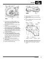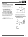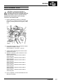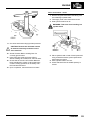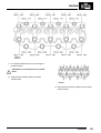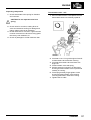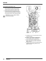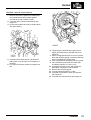
1
300 TDi ENGINE OVERHAUL MANUAL This engine is fitted to the following Models from 1995 onwards: Discovery Defender Range Rover Classic Publication Part No. LRL 0070ENG Published by Rover Technical Communication 1997 Rover Group Limited INTRODUCTION INTRODUCTION References How to use this manual With the engine and gearbox assembly removed, the crankshaft pulley end of the engine is referred to as the front. To assist in the use of this manual the section title is given at the top and the relevant sub-section is given at the bottom each page. This manual contains procedures for overhaul of the engine. For all other information regarding adjustments, removal of oil seals and engine, consult the Repair Manual for the model concerned. This manual is divided into 3 sections: Description and Operation, Overhaul and Data, Torque & Tools. Operations covered in this manual do not include reference to testing the vehicle after repair. It is essential that work is inspected and tested after completion and if necessary a road test of the vehicle is carried out particularly where safety related items are concerned Dimensions The dimensions quoted are to design engineering specification with Service limits where applicable. To assist filing of revised information, each sub-section is numbered from page 1. Individual items are to be overhauled in the sequence in which they appear in this Manual. Items numbered in the illustrations are referred to in the text. Overhaul operations include reference to Service Tool numbers and the associated illustration depicts the tool. Where usage is not obvious the tool is shown in use. Operations also include reference to wear limits, relevant data, torque figures, specialist information and useful assembly details. WARNINGS, CAUTIONS and Notes have the following meanings: WARNING: Procedures which must be followed precisely to avoid the possibility of injury. CAUTION: Calls attention to procedures which must be followed to avoid damage to components. NOTE: Gives helpful information. INTRODUCTION 1 INTRODUCTION REPAIRS AND REPLACEMENTS SPECIFICATION When replacement parts are required it is essential that only Land Rover recommended parts are used. Land Rover are constantly seeking to improve the specification, design and production of their vehicles and alterations take place accordingly. While every effort has been made to ensure the accuracy of this Manual, it should not be regarded as an infallible guide to current specifications of any particular component or vehicle. Attention is particularly drawn to the following points concerning repairs and the fitting of replacement parts and accessories. Safety features and corrosion prevention treatments embodied in the car may be impaired if other than Land Rover recommended parts are fitted. In certain territories, legislation prohibits the fitting of parts not to the manufacturer’s specification. Torque wrench setting figures given in this Manual must be used. Locking devices, where specified, must be fitted. If the efficiency of a locking device is impaired during removal it must be renewed. The terms of the vehicle Warranty may be invalidated by the fitting of other than Land Rover recommended parts. All Land Rover recommended parts have the full backing of the vehicle Warranty. Land Rover Dealers are obliged to supply only Land Rover recommended parts. 2 INTRODUCTION This Manual does not constitute an offer for sale of any particular component or vehicle. Land Rover Dealers are not agents of the Company and have no authority to bind the manufacturer by any expressed or implied undertaking or representation. ENGINE This page is intentionally left blank DESCRIPTION AND OPERATION 1 ENGINE 2 DESCRIPTION AND OPERATION ENGINE CYLINDER BLOCK, PISTONS AND CAMSHAFT 1. 2. 3. 4. 5. 6. 7. 8. 9. 10. 11. 12. 13. 14. 15. 16. 17. 18. 19. Top compression ring 2nd compression ring Oil control ring Piston Gudgeon pin circlips Gudgeon pin Connecting rod Brake servo vacuum pump gasket Core plug Connecting rod bolt Big-end bearing shell Push rod Cam follower slide Roller Cam follower guide Guide retaining bolt Dipstick Dipstick tube Dipstick tube bolt 20. 21. 22. 23. 24. 25. 26. 27. 28. 29. 30. 31. 32. 33. 34. 35. 36. 37. 38. Camshaft Oil jet tube Drive pin Camshaft thrust plate Camshaft bearings Main bearing shell Baffle plate Core plugs Oil pressure switch Thermostatic valve assembly Oil filter head Fuel lift pump Fuel lift pump gaskets Spacer - if fitted Brake servo vacuum pump Crankcase breather pipe Oil filter head gasket Baffle plate gasket Oil filter element DESCRIPTION AND OPERATION 3 ENGINE 4 DESCRIPTION AND OPERATION ENGINE CRANKSHAFT, SUMP AND OIL PUMP 1. 2. 3. 4. 5. 6. 7. 8. 9. 10. 11. 12. 13. Crankshaft Woodruff key Main bearing shell Main bearing cap - front Main bearing cap bolt ’O’ ring - oil pick-up pipe Oil pick-up pipe and strainer Sump bolt Oil drain pipe Sump Gasket - oil drain pipe Main bearing cap - rear Rear main bearing cap oil seal 14. 15. 16. 17. 18. 19. 20. 21. 22. 23. 24. 25. Crankshaft thrust washers Main bearing cap - centre Big-end bearing cap Big-end bearing cap nut Big-end bearing shell Oil jet tube banjo bolt Oil jet tube Oil pump Timing belt rear cover Plug Oil pressure relief valve spring Oil pressure relief valve plunger DESCRIPTION AND OPERATION 5 ENGINE 6 DESCRIPTION AND OPERATION ENGINE ROCKER SHAFT AND COVER 1. 2. 3. 4. 5. 6. 7. 8. 9. Rocker cover flange nuts Sealing washer Oil filler cap Rocker cover Rocker cover gasket Rocker shaft Rocker shaft pedestal Flange bolt Washer 10. 11. 12. 13. 14. 15. 16. 17. 18. Rocker arm bush Adjusting screw Locknut Rocker arm Spacer Pedestal stud Nut Crankcase breather cyclone unit ’O’ ring DESCRIPTION AND OPERATION 7 ENGINE 8 DESCRIPTION AND OPERATION ENGINE CYLINDER HEAD 1. 2. 3. 4. 5. 6. 7. 8. 9. 10. 11. 12. 13. 14. Valve cap Collets Valve spring cup Valve spring Valve spring seat Valve stem seal Valve guide Exhaust valve seat Exhaust valve Inlet valve seat Inlet valve Cylinder head bolt - M12 - long Cylinder head bolt - M12 - short Cylinder head bolt - M10 15. 16. 17. 18. 19. 20. 21. 22. 23. 24. 25. Heater hose adaptor Engine lifting brackets Core plugs Cylinder head gasket Thermostat housing gasket Coolant filler plug Thermostat housing Thermostat Coolant outlet elbow Coolant temperature sensor Sealing washer DESCRIPTION AND OPERATION 9 ENGINE 10 DESCRIPTION AND OPERATION ENGINE TIMING BELT REAR COVER AND GEARS 1. 2. 3. 4. 5. 6. 7. 8. 9. 10. Camshaft oil seal Gasket Crankshaft front oil seal Timing belt rear cover Injection pump drive gear Hub plate Nut - injection pump hub Bolt - injection pump hub plate Camshaft drive gear Washer - camshaft drive gear 11. 12. 13. 14. 15. 16. 17. Bolt - camshaft drive gear Idler pulley Retaining nut Crankshaft gear Bolt - timing belt tensioner pulley Spacer - timing belt tensioner pulley bolt Timing belt tensioner pulley and tensioner bracket 18. Flanged spacer - idler pulley 19. ’O’ ring DESCRIPTION AND OPERATION 11 ENGINE 12 DESCRIPTION AND OPERATION ENGINE TIMING BELT AND FRONT COVER 1. 2. 3. 4. 5. Timing belt Gasket Access plate Bolt - access plate Timing belt front cover 6. 7. 8. 9. 10. Bolts - timing belt front cover Wading plug Oil seal Crankshaft pulley Pulley bolt DESCRIPTION AND OPERATION 13 ENGINE 14 DESCRIPTION AND OPERATION ENGINE OPERATION The 300 TDi is a 4 cylinder, water cooled, turbocharged diesel engine with a capacity of 2.5 litres. The cast iron cylinder block is integral with the crankcase and incorporates direct bored cylinders. The crankshaft is carried in 5 main bearings, end-float being controlled by thrust washers which are positioned on both sides of the centre main bearing. The flywheel/drive plate housing is an aluminium alloy casting secured to the rear of the cylinder block, it also forms the mounting for the starter motor. A plugged aperture in the housing allows access for the insertion of the timing pin. The aluminium alloy cylinder head carries a conventional rocker shaft and rockers, operating 2 valves per cylinder via camshaft followers and push rods from a single camshaft, supported in the cylinder block by 4 bearings and driven by a gear and toothed belt from the crankshaft. A lobe formed between the 2 inner bearing journals provides drive for the fuel lift pump and another lobe, between the 2 drive end journals provides drive for the brake servo pump. Camshaft end-float is controlled by a thrust plate bolted to the cylinder block. Graphite coated, aluminium alloy pistons are fitted with 2 compression and an oil control ring and are secured to the connecting rods by semi-floating gudgeon pins which are an interference fit in the small end bush. A swirl chamber is incorporated in the piston crown to facilitate combustion. The timing case consists of cast aluminium alloy front and rear covers which house the oil pump, crankshaft and camshaft front oil seals and which also carry the fuel injection pump and drive belt idler pulley. Housed within the timing case housing is the crankshaft gear which provides drive for the camshaft and fuel injection pump gears via a rubber toothed belt. DESCRIPTION AND OPERATION 15 ENGINE 16 DESCRIPTION AND OPERATION ENGINE Lubrication The engine lubrication system is of the wet sump type, oil pressure being provided by the rotor type oil pump (1) driven directly by the crankshaft. Oil is drawn from the sump (2) through the strainer (3), suction pipe (4) and passes through internal drillings in the cylinder block to an external, full flow filter (5). Further drillings feed oil to the cylinder block main oil gallery (6) which, in turn, supplies the crankshaft main bearings (7). Cross drillings in the crankshaft carry oil to the connecting rod big-end bearings (8). The camshaft bearings (9) are supplied with oil from the main oil gallery. An internal oilway from the camshaft front bearing connects the cylinder block to the cylinder head and feeds oil to the rocker shaft assembly (10), lubricating the valves and springs. The pistons, gudgeon pins and small end bushes are lubricated and cooled by oil jets (11) which are supplied from the main oil gallery via relief valves which allow the oil to flow at a pre-determined pressure. Oil pressure is controlled by a pressure relief valve (12) incorporated in the timing case housing together with the oil pump. The valve allows excess oil to be recirculated back into the oil feed gallery. The rotor type oil pump is driven by 2 flats machined on the front of the crankshaft. Oil cooling is maintained by an oil cooler which is integral with the radiator and linked to adaptors on the oil filter head by pre-formed feed and return hoses. A thermostatic valve in the filter head allows oil to flow to the cooler when it reaches a pre-determined temperature. DESCRIPTION AND OPERATION 17 ENGINE Crankcase ventilation system A breather cyclone unit (1), fitted to the right hand side of the rocker cover controls the rate at which air is purged from the sump, via a hose (2) from the camshaft side cover to the rocker cover and extracts 18 DESCRIPTION AND OPERATION oil from the gaseous atmosphere. The oil then drains back to the sump through a hose and flanged pipe connection (3). The residues are drained-off from the top of the cyclone breather and pass through a hose (4) into the engine via the turbocharger where they are burned in the combustion chamber. ENGINE TIMING BELT, TENSIONER AND GEARS Timing belt - remove 4. Position tool LRT-12-049 and thrust button, part of tool LRT-12-031 to crankshaft pulley, remove pulley, recover Woodruff key. 1. Position tool LRT-12-080 to crankshaft pulley, retain with 4 bolts. 2. Restrain crankshaft using tool LRT-12-080 and remove crankshaft pulley flange head bolt. NOTE: Bolt and washer fitted to early engines. 3. Remove tool LRT-12-080 . 5. Using sequence shown, progressively slacken then remove 14 bolts securing timing belt front cover. OVERHAUL 1 ENGINE Automatic gearbox 12. Rotate crankshaft clockwise using crankshaft pulley bolt until tool LRT-12-044 can be inserted through hole in engine plate and into slot in drive plate. 6. Remove timing belt front cover. 7. Remove and discard gasket. 8. Remove and discard crankshaft front oil seal from timing belt front cover. 9. Temporarily fit crankshaft pulley bolt to crankshaft. Manual gearbox 10. Remove plug from bottom of flywheel housing. 11. Rotate crankshaft clockwise using crankshaft pulley bolt until tool LRT-12-044 can be located in slot in flywheel. CAUTION: Do not rotate crankshaft anti-clockwise and do not use camshaft or fuel injection pump gear bolts to rotate crankshaft. 2 OVERHAUL CAUTION: Do not rotate crankshaft anti-clockwise and do not use camshaft or fuel injection pump gear bolts to rotate crankshaft. ENGINE All engines 13. Check that timing mark on camshaft pulley is aligned with mark on timing belt rear cover and the crankshaft Woodruff key is aligned with the arrow cast on the rear cover. 14. Remove crankshaft pulley bolt. 15. Insert timing pin LRT-12-045 into fuel injection pump gear hub plate and injection pump hub. 18. Slacken but do not remove bolt securing timing belt tensioner pulley, move pulley until tension is removed from belt. 19. Remove nut and washer securing idler pulley. 20. Release idler pulley from timing belt, remove pulley. 21. Release timing belt from gears, discard belt. 16. Slacken but do not remove centre bolt securing camshaft drive gear to camshaft. 17. If timing belt is to be refitted, mark direction of rotation on outside surface of belt with chalk or similar soft material. OVERHAUL 3 ENGINE Timing belt tensioner and timing gears - remove 5. Remove centre bolt and washer securing camshaft timing gear, remove gear and hub plate as an assembly. 1. Remove crankshaft gear using tools LRT-12-031 and LRT-12-078, recover Woodruff key from crankshaft. 2. Remove and discard ’O’ ring. 3. Remove bolt and slotted washer securing timing belt tensioner pulley, remove pulley together with tensioner bracket. 4. Recover flanged spacer from idler pulley stud. 4 OVERHAUL NOTE: Later engines are fitted with a flange head bolt. CAUTION: Do not remove 3 bolts securing hub plate to gear. ENGINE Inspecting components 1. Check timing gear teeth for burrs. 2. Remove all traces of gasket from timing belt front and rear covers using suitable gasket removal spray and a plastic scraper. 6. Remove 3 bolts securing fuel injection pump gear and hub plate to pump hub. CAUTION: Do not remove nut securing hub to fuel injection pump. 7. Remove timing pin LRT-12-045. 8. Remove fuel injection pump gear and hub plate. OVERHAUL 5 ENGINE Timing belt tensioner and gears - refit 1. Smear a new ’O’ ring with engine oil and fit to crankshaft. 2. Fit Woodruff key in slot in crankshaft. 3. Fit crankshaft gear on to crankshaft and using a soft mallet, tap gear fully home. 5. Position fuel injection pump gear and hub plate to fuel injection pump hub ensuring that cut-out in hub plate is aligned with timing pin hole in pump hub. 6. Fit 3 bolts, position slots in gear mid-way under bolt heads, lightly tighten bolts. CAUTION: Do not fit bolts through elongated slots in hub plate. Ensure gear does not move as bolts are tightened. 7. Insert timing pin LRT-12-045 in hub plate and injection pump hub. If timing pin cannot be inserted, slacken bolts and rotate gear until pin can be fitted, lightly tighten bolts. 4. Position camshaft timing gear and hub plate to camshaft, fit bolt and washer, finger tighten bolt. Do not tighten bolt at this stage. NOTE: Later engines are fitted with a flange head bolt. 6 OVERHAUL ENGINE NOTE: Flywheel illustrated 8. Position flanged spacer on idler pulley stud. 9. Fit timing belt tensioner pulley and bracket ensuring that hole in tensioner bracket is located on flanged spacer. 10. Fit slotted washer with the slot vertical and fit bolt, finger tight. 11. Temporarily fit crankshaft pulley bolt to crankshaft. 12. Manual gearbox: Rotate crankshaft clockwise using crankshaft pulley bolt until tool LRT-12-044 can be inserted in slot in flywheel. 13. Automatic gearbox: Rotate crankshaft clockwise using crankshaft pulley bolt until tool LRT-12-044 can be inserted in slot in drive plate. 14. Check that crankshaft Woodruff key is aligned with arrow on timing belt rear cover. 15. If necessary, rotate camshaft timing gear using the centre bolt until timing mark on gear is aligned with timing mark on timing belt rear cover. 16. Remove crankshaft pulley bolt. OVERHAUL 7 ENGINE Timing belt - refit and adjust tension Adjust tension Refit 1. Ensure tools LRT-12-044 and LRT-12-045 are still fitted. 1. Using the fingers only, fit a new timing belt to timing gears keeping slack portion of belt on idler pulley side of belt. If necessary, rotate fuel injection pump gear anti-clockwise to align gear teeth with those of timing belt. CAUTION: If original timing belt is to be refitted, ensure direction of rotation mark is facing correct way. 2. Fit idler pulley. 3. Fit idler pulley nut and tighten to 45 Nm. 4. Ensure that timing belt is correctly located on timing gears. 5. Check that tensioner pulley bolt is finger tight. 6. Temporarily fit crankshaft pulley bolt to crankshaft. 8 OVERHAUL 2. Position a dial type torque wrench and suitable extension to hole in tensioner bracket keeping the torque wrench positioned vertically. 3. Tension timing belt to : Used belt - 12 Nm New belt - 15 Nm 4. Keeping timing belt at the correct tension, tighten tensioner bolt to 45 Nm. ENGINE 16. Support timing belt front cover on suitable blocks of wood. 17. Smear a new crankshaft oil seal with engine oil. 18. Using tool LRT-12-077, fit oil seal from inside face of front cover. 5. Check that timing pin LRT-12-045 moves freely in and out of injection pump hub, if pin does not move freely, slacken 3 bolts, move gear slightly and re-check. 6. When timing pin moves freely, tighten 3 bolts to 25 Nm. 7. Remove timing pin LRT-12-045 and flywheel/drive plate locking tool LRT-12-044. 8. Rotate crankshaft twice in a clockwise direction using crankshaft pulley bolt until flywheel/drive plate locking tool LRT-12-044 can be refitted. 9. Slacken timing belt tensioner securing bolt and re-tension timing belt. 10. Tighten tensioner bolt to 45 Nm. 11. Fit timing pin LRT-12-045 into fuel injection pump gear hub plate and pump hub. If timing pin cannot be inserted, slacken injection pump gear bolts, rotate pump shaft using shaft nut until pin slides easily into pump hub, Tighten bolts to 25 Nm. 12. Tighten camshaft gear bolt to 80 Nm. 13. Remove timing pin and flywheel/drive plate locking tools. 14. Fit plug to flywheel housing, tighten to 12 Nm. 15. Remove crankshaft pulley bolt. 19. Fit a dry, new gasket to timing belt rear cover. 20. Position timing belt front cover to rear cover. 21. Fit bolts of the correct length in positions shown. OVERHAUL 9 ENGINE 22. Tighten bolts in sequence shown to 25 Nm. 23. Lightly oil crankshaft spigot, fit Woodruff key and crankshaft pulley. 24. Position tool LRT-12-080 to crankshaft pulley, retain tool using 4 bolts. 25. Fit crankshaft pulley flange head bolt. 26. Restrain crankshaft and tighten bolt to 80 Nm,then further 90.° 27. Remove tool LRT-12-080. 10 OVERHAUL ENGINE ROCKER SHAFT Remove 5. Remove 3 flange nuts securing rocker cover, recover sealing washers. 6. Remove rocker cover, remove and discard gasket. 1. Disconnect breather hoses from crankcase breather cyclone unit. 2. Remove bolt securing cyclone unit to rocker cover. 3. Remove cyclone unit, remove and discard ’O’ ring. 4. Disconnect breather hoses from cylinder block and rocker cover. 7. Slacken locknut on each tappet adjusting screw, slacken adjusting screws until they are clear of push rods. 8. Working from the centre outwards, progressively slacken then remove 3 nuts and 2 bolts securing rocker shaft pedestals to cylinder head. CAUTION: Insert a slave bolt into pedestals 1 and 5 to prevent components sliding off shaft. 9. Remove rocker shaft assembly. OVERHAUL 11 ENGINE Rocker shaft - dismantling 1. Suitably identify each component to its fitted position. 10. Withdraw push rods. 11. Remove valve caps. CAUTION: Keep push rods and valve caps in their fitted order. 2. Remove locknut and tappet adjusting screw from each rocker. 3. Remove slave bolt and pedestal from end of rocker shaft. 4. Remove washer, rocker arm and spacer followed by second rocker arm, spacer and pedestal. 5. Repeat above procedures until all components are removed. 12 OVERHAUL ENGINE Inspecting components 1. Measure and record diameter of rocker shaft at one of the pedestal locations. 2. Measure and record diameter of rocker shaft at each of the rocker arm locations. 3. Compare measurements obtained and calculate difference between diameters. If wear at any rocker shaft location exceeds 0.025 mm, a new rocker shaft must be fitted. 4. Check rocker arm pads for signs of wear, replace rocker arms as necessary. 5. Check threads and ball ends of each tappet adjusting screw for wear. Pay particular attention to ball ends, replace any showing signs of flattening on the ball or damage to threads. 6. Check that each nut runs freely on adjusting screw threads. 7. Check each push rod for signs of wear and for straightness, replace as necessary. 8. Check valve caps for signs of wear, replace as necessary. 9. Check rocker arm bushes for scoring and wear. 10. Assemble each rocker arm to its fitted location on rocker shaft and check clearance of bush to shaft does not exceed 0.12 mm. 11. If clearance exceeds figure given, bushes must be replaced. Rocker arm bushes - replace 1. Support rocker arm on bed of hand press. 2. Using a suitable piloted mandrel, press bush out of rocker arm. 3. Lubricate replacement bush with engine oil and press into rocker arm ensuring that lubrication holes in bush and arm are aligned. 4. Check that lubrication holes in each rocker arm are clear. 5. Check that lubrication holes in rocker shaft are clear. 6. Check spacers and washers for wear, replace as necessary. OVERHAUL 13 ENGINE Rocker shaft - assembling 1. Lubricate all components with engine oil. 2. Assemble rocker arms, spacers, washers and pedestals to rocker shaft ensuring that they are in their original fitted positions. 3. Retain pedestals 1 and 5 with slave bolts. 14 OVERHAUL Rocker shaft - refit 1. Lubricate push rods with engine oil and fit to their original positions. Ensure that ball end of each push rod is correctly located in each cam follower slide. 2. Screw each tappet adjusting screw into its respective rocker arm until ball end is flush with underside of arm; fit but do not tighten locknuts. 3. Lubricate valve pads with engine oil and fit to their original positions. 4. Position rocker shaft to cylinder head, fit but do not tighten 3 nuts. 5. Remove slave bolts from pedestals 1 and 5, fit but do not tighten 2 bolts. 6. Locate each push rod in turn beneath its respective tappet adjusting screw and tighten each screw until ball end locates in recess in push rod. 7. Working from the centre outwards, progressively tighten 3 nuts and 2 bolts to 5 Nm. ENGINE 8. Make a suitable pointer from welding rod and position it to number 1 pedestal stud. 9. Temporarily fit a nut to secure pointer to stud. 10. Assemble degree plate LRT-12-007 to a suitable torque wrench or extension bar. 11. Tighten the centre pedestal nut a further 50 °. 12. Tighten 2 pedestal bolts and number 5 pedestal nut a further 50 °. 13. Remove pointer and secure it to number 5 pedestal stud. 14. Tighten number 1 pedestal nut a further 50 °. 15. Remove pointer. 16. Adjust valve clearances. 17. Thoroughly clean mating faces of rocker cover and cylinder head, remove all traces of gasket material using gasket removal spray and a plastic scraper. OVERHAUL 15 ENGINE 18. Check sealing washers for damage or distortion, replace as necessary. 19. Position a new gasket - dry to rocker cover. 20. Position rocker cover to cylinder head, fit 3 flange nuts and working from centre outwards, tighten to 10 Nm. 21. Lubricate a new ’O’ ring with engine oil and fit to crankcase breather cyclone unit. 22. Fit cyclone unit to rocker cover, fit bolt and tighten to 9 Nm. 23. Connect breather hoses to cyclone unit, rocker cover and cylinder block. 16 OVERHAUL ENGINE VALVE CLEARANCES - ADJUST CAUTION: To prevent possibility of damage to cam follower seatings, it is essential that ball ends of tappet adjusting screws are seated in recess in push rods and that ball end of each push rod is correctly located in cam follower slide. 1. Rotate crankshaft by means of crankshaft pulley bolt in a clockwise direction until number 8 valve ( counting from front of engine ) is fully open. 2. Using feeler gauges and a screwdriver, adjust clearance of number 1 valve. Valve clearance - all valves = 0.20 mm 3. Tighten tappet adjusting screw locknut when clearance is correct. 4. Adjust the remaining valve clearances in the following sequence: Adjust number 3 clearance with number 6 valve fully open Adjust number 5 clearance with number 4 valve fully open Adjust number 2 clearance with number 7 valve fully open Adjust number 8 clearance with number 1 valve fully open Adjust number 6 clearance with number 3 valve fully open Adjust number 4 clearance with number 5 valve fully open Adjust number 7 clearance with number 2 valve fully open 5. Upon completion, re-check all clearances and adjust as necessary. OVERHAUL 17 ENGINE CYLINDER HEAD Remove 1. Remove rocker shaft. 2. Remove fuel injectors. 3. Remove glow plugs. 8. Remove 2 bolts securing coolant outlet elbow. 9. Remove coolant outlet elbow. 10. Remove thermostat from housing. 4. Using sequence shown, progressively slacken then remove and discard 18 bolts securing cylinder head. 5. Using assistance, remove cylinder head. NOTE: Dowel located. 6. Remove cylinder head gasket. CAUTION: Identify cylinder head gasket thickness by the number of holes in the edge of the gasket between numbers 3 and 4 injector ports. Replacement gasket must be of the same thickness as the original unless a replacement cylinder head, crankshaft and/or pistons are fitted.- See Cylinder head gasket selection. 7. Discard cylinder head gasket. 18 OVERHAUL 11. Remove 4 bolts securing thermostat housing to cylinder head, remove housing. 12. Remove and discard gasket. 13. Remove all traces of gasket using suitable gasket removal spray and a plastic scraper. ENGINE Valves and springs - remove 1. Support cylinder head clear of valves, use a hollow drift and tap each valve spring cap to free collets. 2. Position cylinder head on its side. 14. Remove 2 bolts securing engine front lifting bracket, remove bracket. 3. Using tool LRT-12-034 compress valve spring. 4. Remove 2 collets from valve stem. 5. Remove tool LRT-12-034. OVERHAUL 19 ENGINE Cylinder head - inspection 1. Decarbonise cylinder head. 2. Examine cylinder head for cracks, pay particular attention to area between inlet and exhaust valve seats. Cracks indicate engine has overheated and cylinder head must be replaced. 3. Check core plugs for signs of corrosion and leakage, replace as necessary. 6. Remove spring cup, valve spring and spring seat. Keep components in their fitted order. 7. Remove and discard valve stem oil seal. 8. Remove valve, and retain in fitted order. 9. Repeat above procedures for remaining valves. 4. Check cylinder head for warping using a straight edge and feeler gauges. Maximum warping = 0.08 mm CAUTION: Cylinder head must not be refaced, if warping exceeds figure given, head must be replaced. 5. Check valve seat inserts for burning, pitting or damage, replace inserts if pitting cannot be removed by valve lapping-in or refacing. 20 OVERHAUL ENGINE Valve springs - inspection 1. Check free length of each spring = 46.28 mm 2. Check that end coils of each spring are square to body of spring. Valves and guides - inspection 1. Remove carbon from valves. 2. Examine head of each valve for cracks and burning and valve seat for pitting or burning, replace valves as necessary. 3. Check valve seating faces for pitting, if light pitting cannot be removed during valve grinding operations, valves may be refaced. CAUTION: If refacing results in valve head stand down being exceeded, valves must be replaced. 4. Check valve seating face angles. Inlet = 60 °00’ to 60 °30’ - included angle =120 ° Exhaust = 45 °00’ to 45 °30’ - included angle = 90° 5. Reface or replace valves as necessary. 6. Check each valve stem for wear, measure at each end and centre of valve stem. Inlet = 7.96 mm Exhaust = 7.94 mm 7. Replace any valve with stems that are worn. OVERHAUL 21 ENGINE Valve guides - renew 8. Insert a new valve into each guide in turn and with head of valve positioned 8.0 mm above seat insert, measure side to side movement of valve head using a suitable DTI. Maximum valve head movement = 0.15 mm 9. Replace any valve guide which permits valve head movement in excess of the above figure. 1. Support cylinder head, combustion face upwards on blocks of wood. 2. Using tool LRT-12-036, drift valve guide out of cylinder head, discard guide. 3. Clean valve guide bore. 4. Heat cylinder head uniformily to 120 °C. WARNING: Take care when handling heated cylinder head. 22 OVERHAUL ENGINE Valve seat inserts - refacing CAUTION: Prior to refacing valve seats, check valve head stand down. If, after refacing, valve head stand down will be below limits, seat inserts must be replaced. 5. Position cylinder head on bed of hand press. 6. Position replacement valve guide to cylinder head, ensuring that groove for valve stem seal is facing away from cylinder head. 7. Position distance piece, tool LRT-12-515 and valve guide replacer LRT-12-046 to valve guide. 8. Press valve guide into cylinder head until distance piece contacts face of head; remove tools. 9. Allow cylinder head to air cool. 1. Support cylinder head on its side on suitable blocks of wood. 2. Loosely assemble pilot, tool LRT-12-502 and a suitable expandable collet, ensuring that chamfered end of expander is towards the collet. OVERHAUL 23 ENGINE 3. Lightly lubricate the tool with engine oil. 4. Insert pilot into valve guide from combustion chamber side of cylinder head until shoulder of pilot contacts guide. 5. Check that collet is fully inserted into valve guide and expand collet against the guide using a suitable tommy bar. 24 OVERHAUL 6. Assemble the 45 °cutter, MS621 (exhaust valves) and 60 °cutter, MS627 (inlet valves) to tool LRT-12-501. 7. Position tool LRT-12-501 and appropriate cutter to valve seat insert to be refaced. 8. Using the Allen key, adjust position of cutter so that centre of cutter contacts area of seat insert to be cut. ENGINE Valve seat inserts - renew 1. Remove original valve seat insert taking care not to damage cylinder head. 2. Thoroughly clean valve seat insert recess. 3. Heat cylinder head to 65 °C. WARNING: Take care when handling hot cylinder head. 9. Cut valve seat insert using light hand pressure. CAUTION: Remove the minimum amount of material necessary to obtain correct valve seat face. 10. Smear Prussian Blue to seating face of a correctly ground valve. 11. Insert valve into guide and press it firmly, without rotating on to seat insert, remove valve. 12. Check that an even line of Prussian Blue has been transferred to centre of valve seat insert, continue cutting operation as necessary until this has been achieved. 13. Upon completion, remove all traces of swarf. 4. Place cylinder head on bed of hand press and using a suitable mandrel, press replacement seat insert into recess. 5. Allow cylinder head to air cool. 6. Check that seat insert is seated squarely in recess. OVERHAUL 25 ENGINE Lapping-in valves Valve head stand down - checking 1. Lap each valve to its seat using grinding paste. 2. Apply Prussian Blue to valve seat insert. Insert valve into guide and press it firmly, without rotating on to seat. 3. Remove valve and check that a continuous, even line of Prussian Blue has been transferred to valve face, continue lapping-in valve as necessary. NOTE: Line does not have to be across whole width of valve face. 4. Remove all traces of grinding paste on completion. 5. Check valve head stand down of each valve. 1. Insert each valve into its respective guide. 2. Using a straight edge and feeler gauges, check and record stand down of each valve head. 3. Compare figures obtained with those given below. If any valve head has a stand down outside that specified, valve and/or seat insert must be replaced. Valve head stand down: Inlet valve A= 0.81 to 1.09 mm Exhaust valve B= 0.86 to 1.14 mm 26 OVERHAUL ENGINE Valves and springs - refit 1. Lubricate valve stems, guides, spring seats, valve springs, spring cups and collets with engine oil. 2. Lubricate new valve stem oil seals with engine oil and fit to valve guides. 3. Fit spring seat, insert valve into its respective guide, fit valve spring and spring cup. 4. Compress valve spring using tool LRT-12-034 and fit collets. 5. Remove tool LRT-12-034. 6. Tap spring cup with a soft mallet to ensure that collets are correctly seated. 7. Repeat above procedures for remaining valves. Cylinder head gasket selection CAUTION: New cylinder head gasket should be same thickness as the original. If, however, cylinder head, pistons or crankshaft have been replaced, it will be necessary to check piston stand proud in order to determine the correct thickness of gasket. 1. Position a magnetic base DTI to cylinder block top face adjacent to number 1 cylinder bore. 2. Position stylus of gauge to cylinder block top face on edge of number 1 cylinder bore; zero gauge. 3. Rotate crankshaft in a clockwise direction until numbers 1 and 4 pistons are at TDC. 4. Position stylus of DTI gauge near edge of piston crown, measure and record number 1 piston stand proud. Measurement must be taken at front and rear of piston and highest protrusion figure recorded. 5. Repeat above procedures for remaining pistons. OVERHAUL 27 ENGINE 6. From all of the readings obtained, determine highest protrusion figure and select the appropriate cylinder head gasket. Protrusion 0.50 to 0.60 mm - select gasket with 1 identification hole. Protrusion 0.61 to 0.70 mm - select gasket with 2 identification holes. Protrusion 0.71 to 0.80 mm - select gasket with 3 identification holes. Protrusion 0.81 to 0.90 mm - select gasket with 0 identification holes. NOTE: Identification holes are located on the edge of the gasket. 7. Remove DTI. 8. Rotate crankshaft in a clockwise direction until all pistons are half-way up cylinder bores. 28 OVERHAUL Cylinder head - refit 1. Ensure that mating faces of cylinder head and block are clean and dry and that 2 locating dowels are fitted in cylinder block. 2. Lubricate threads of new cylinder head bolts with engine oil. 3. Check that cylinder head bolt holes in cylinder block are clean and dry. 4. Rotate crankshaft in a clockwise direction until pistons are half-way up cylinder bores. 5. Position the selected cylinder head gasket on cylinder block ensuring that word "TOP" is facing upwards. 6. Using assistance, fit cylinder head ensuring that it is located on dowels. ENGINE 7. Fit cylinder head bolts of the correct length in positions shown. CAUTION: Do not drop bolts into cylinder block. 8. Tighten bolts until bolt heads just contact cylinder head. 9. Using sequence shown, tighten cylinder head bolts to 40 Nm. OVERHAUL 29 ENGINE 10. Assemble degree plate LRT-12-007 to a torque wrench or extension bar. 11. Make a suitable pointer from welding rod and attach it to the rocker shaft pedestal bolt hole adjacent to number 1 cylinder head bolt. 12. Using sequence shown, tighten cylinder head bolts a further 60°. NOTE: Re-position the pointer as necessary to enable degree of tightening to be measured. 13. Using sequence shown, tighten each bolt a further 60°. CAUTION: Bolts must be tightened in sequence 60 °at a time - never 120 °in one operation. 14. Using sequence shown, tighten bolts numbers 1, 2, 7, 8, 9, 10, 15, 16, 17 and 18 a further 20°. 15. Remove pointer. 30 OVERHAUL 16. Position a new thermostat housing gasket to cylinder head. 17. Fit thermostat housing, fit bolts and tighten to 25 Nm. 18. Position thermostat in housing. 19. Fit coolant outlet elbow, fit bolts and tighten to 25 Nm. 20. Position engine front lifting bracket to cylinder head, fit 2 bolts and tighten to 25 Nm. 21. Fit fuel injectors. 22. Fit glow plugs. 23. Fit rocker shaft assembly. ENGINE TIMING BELT REAR COVER AND OIL PUMP Oil pump and oil pressure relief valve - remove Oil pump Timing belt rear cover - remove 1. Remove timing belt, tensioner and gears. 2. Remove fuel injection pump. 3. Remove sump and oil pick-up pipe. 4. Using sequence shown, progressively slacken then remove bolts securing timing belt rear cover; remove cover. 5. Remove and discard gasket. 6. Remove and discard camshaft and crankshaft front oil seals. 1. Make suitable alignment marks between oil pump and timing belt rear cover. 2. Progressively slacken then remove 7 screws securing oil pump cover. 3. Remove oil pump cover. 4. Make suitable alignment marks between oil pump inner and outer rotors and outer rotor and timing belt rear cover. OVERHAUL 31 ENGINE Oil pressure relief valve 1. Remove plug retaining oil pressure relief valve. 2. Withdraw spring and plunger. Inspecting components 1. Check rotor clearances. A - Outer rotor to housing = 0.025 to 0.075 mm B - Inner rotor to outer rotor = 0.025 to 0.075 mm C - Rotor end-float = 0.026 to 0.135 mm 2. 3. 4. 5. Remove inner and outer rotors. Check rotors for damage, wear and scoring. Check oil pump cover for wear and scoring. Check oil pressure relief valve spring free length is 68.0 mm. 6. Check plunger and relief valve bore for wear and scoring. 7. Clean all traces of sealant from oil pump cover using solvent from kit GUG 705548GM. 8. Remove all traces of sealant from relief valve plug threads in oil pump body. CAUTION: Do not use a tap. 32 OVERHAUL ENGINE Oil pump and oil pressure relief valve - refit Oil pump 1. Thoroughly clean timing belt rear cover, remove all traces of gasket using suitable gasket removal spray and a plastic scraper. Remove all traces of sealant using solvent from kit GUG 705548GM. 2. Ensure oil pump cover screw holes are clean and dry. 3. Clean oil pump rotors and recess, lubricate rotors and recess with engine oil. Oil pressure relief valve 1. Thoroughly clean oil pressure relief valve plunger, spring and relief valve bore then lubricate components with engine oil. 2. Insert plunger and spring into bore. 3. Smear threads of relief valve plug with Loctite 577. 4. Fit plug and tighten to 17 Nm. CAUTION: Ensure alignment marks made during dismantling are not erased. 4. Position inner and outer rotors in housing ensuring that reference marks are aligned. 5. Apply bead of sealant from kit to outer edge of oil pump cover, fit cover to housing ensuring that reference marks are aligned. 6. Fit oil pump cover, fit and progressively tighten 7 screws. 7. Check that pump rotates freely. OVERHAUL 33 ENGINE Timing belt rear cover - refit 1. Remove all traces of gasket material from cylinder block using suitable gasket removal spray and a plastic scraper. 2. Screw 2 slave guide studs into cylinder block. 3. Fit new gasket over guide studs. 4. Note position of oil pump drive flats on crankshaft. 5. Rotate oil pump inner rotor to align with drive flats on crankshaft and position timing belt rear cover on guide studs. 6. Fit timing belt rear cover. CAUTION: Do not remove guide studs at this stage. 7. Fit 8 bolts of the correct length in positions shown, remove guide studs and fit remaining 2 bolts. 34 OVERHAUL ENGINE 8. Using sequence shown, tighten bolts to 25 Nm. 9. Fit oil pick-up pipe and sump. 10. Lubricate a new crankshaft front oil seal with engine oil. 13. Fit oil seal using tool LRT-12-082. 14. Fit fuel injection pump. 15. Fit timing belt, tensioner and gears. 11. Fit oil seal using tool LRT-12-079. 12. Lubricate a new camshaft oil seal with engine oil. OVERHAUL 35 ENGINE OIL FILTER HEAD Thermostatic valve - remove Remove 1. Remove and discard oil filter element. 2. Remove 4 bolts securing filter head to cylinder block. 3. Remove filter head, remove and discard gasket. 1. Secure oil filter head in a soft-jawed vice with thermostatic valve vertically upwards. 2. Remove 2 bolts securing thermostatic valve extension housing to oil filter head. 3. Remove extension housing, remove and discard ’O’ ring. 4. Withdraw thermostatic valve and spring. CAUTION: Do not separate valve from spring. 36 OVERHAUL ENGINE Inspecting components 1. Check thermostatic valve spring for distortion and corrosion. Thermostatic valve - refit 1. Secure oil filter head in a soft-jawed vice with thermostatic valve bore vertically upwards. CAUTION: Do not separate valve from spring. 2. Check valve for corrosion, seating faces of valve and extension housing for damage and pitting; replace valve as an assembly. 3. Check valve bore for corrosion. Light corrosion must be removed from valve bore using grade 600 emery cloth soaked in oil. 4. Check oil passages in oil filter head are clear. 2. Lubricate a new ’O’ ring with engine oil and fit to thermostatic valve extension housing. 3. Lubricate thermostatic valve and bore with engine oil. 4. Fit thermostatic valve and spring. 5. Position extension housing to oil filter head ensuring that thermostatic valve is positioned centrally in housing. 6. Fit and progressively finger tighten 2 bolts ensuring that thermostatic valve remains correctly positioned in extension housing. 7. Tighten bolts to 9 Nm. OVERHAUL 37 ENGINE Oil filter head - refit 1. Remove all traces of gasket from oil filter head and cylinder block using suitable gasket removal spray and a plastic scraper. 2. Smear a new gasket with engine oil and position on oil filter head. 3. Fit oil filter head, fit 4 bolts and tighten to 45 Nm. 4. Smear sealing ring of new oil filter element with engine oil and fit to oil filter head. 5. Plug open pipe connections to prevent ingress of dirt. 38 OVERHAUL FUEL INJECTION PUMP Remove 1. Remove timing belt. 2. Remove fuel pipes from pump and injectors. 3. Ensure that timing pin LRT-12-045 is inserted in injection pump gear hub plate and injection pump hub. 4. Remove 3 bolts securing hub and injection pump gear to injection pump, remove timing pin LRT-12-045 and gear. CAUTION: Do not remove nut securing hub to pump. ENGINE 5. Remove 3 bolts securing mounting bracket and baffle plate to cylinder block. 6. Remove 2 bolts securing mounting bracket to injection pump, remove bracket. 7. Remove banjo bolt securing fuel spill return pipe to injection pump, discard sealing washers. CAUTION: Plug open connections to prevent ingress of dirt. 8. Remove 3 nuts securing injection pump to timing belt rear cover, remove injection pump. OVERHAUL 39 ENGINE FUEL LIFT PUMP Refit 1. Position injection pump to timing belt rear cover, fit nuts and tighten to 25 Nm. 2. Fit fuel spill return pipe, fit banjo bolt and 2 new sealing washers. 3. Tighten banjo bolt to 25 Nm. 4. Position mounting bracket to injection pump and cylinder block, fit and finger tighten bolts. 5. Tighten mounting bracket bolts to 25 Nm in the following order: Mounting bracket to cylinder block Mounting bracket to injection pump Remove 6. Fit fuel pipes. 1. Disconnect fuel delivery pipe from fuel lift pump, discard sealing washers. CAUTION: Plug open connections to prevent ingress of dirt. 7. Position injection pump gear and hub plate to injection pump hub ensuring that cut-out in hub plate is aligned with timing pin hole in pump hub. 8. Fit 3 bolts, position slot in gear mid-way under bolt heads, lightly tighten bolts. NOTE: Do not fit bolts through elongated slots in hub plate. Bolts are fully tightened after timing belt has been adjusted. 9. Insert timing pin LRT-12-045 in hub plate and injection pump hub. 10. Fit and tension timing belt. 40 OVERHAUL ENGINE Refit 1. Remove all traces of gasket using suitable gasket removal spray and a plastic scraper. 2. Position new gaskets and spacer to fuel lift pump. 3. Fit fuel lift pump ensuring that operating lever is correctly positioned on camshaft. 4. Fit bolts and tighten to 25 Nm. 5. Position fuel delivery pipe to fuel lift pump, fit banjo bolt and 2 new sealing washers. CAUTION: Do not fully tighten banjo bolt until pipe is connected to fuel filter. 2. Remove 2 bolts securing fuel lift pump to cylinder block, remove pump, gasket, spacer and 2nd gasket. 3. Discard gaskets. OVERHAUL 41 ENGINE FUEL INJECTORS Remove 2. Remove banjo bolt securing fuel spill return pipes to injector, remove and discard 2 sealing washers. CAUTION: Plug broken connections to prevent ingress of dirt. 3. Remove nut securing injector clamp, remove clamp. 4. Remove injector, remove and discard sealing washer. 1. Disconnect each pair of fuel pipes from fuel injection pump and injectors. WARNING: Do not attempt to remove injectors using engine compression, either use an open ended spanner on injector body and rotate injector until it is released or use a slide hammer and suitable adaptor. 5. Repeat above procedures to remove remaining injectors. 42 OVERHAUL ENGINE Refit 1. Clean all traces of carbon from injector ports. 2. Fit a new sealing washer to injector, insert injector into port ensuring that spill return banjo bolt hole faces away from cylinder head. 3. Position injector clamp to injector and cylinder head stud ensuring that raised ’pip’ on concave face of clamp faces upwards. 4. Fit and tighten injector clamp nut to 25 Nm. 5. Position spill return pipes to injector, fit banjo bolt and 2 new sealing washers. 6. Tighten banjo bolt to 10 Nm. 7. Repeat above procedures for remaining injectors. 8. Position fuel pipes to injector and fuel injection pump, tighten connections. GLOW PLUGS Remove 1. Remove nut and washer securing harness to glow plug, release harness from plug. 2. Remove glow plug. 3. Repeat above procedures for remaining plugs. Refit 1. Fit glow plug and tighten to 20 Nm. 2. Connect harness to glow plug, fit and tighten nut. 3. Repeat above procedures for remaining plugs. OVERHAUL 43 ENGINE BRAKE SERVO VACUUM PUMP Remove 1. Ensure that number 1 piston is at TDC. CAUTION: Rotate crankshaft in a clockwise direction. Refit 1. Remove all traces of gasket using suitable gasket removal spray and a plastic scraper. 2. Ensure number 1 piston is still at TDC. 3. Fit vacuum pump, fit and finger tighten 5 bolts in their original positions. NOTE: The sixth bolt is fitted when air cleaner bracket is fitted. 4. Tighten bolts progressively by diagonal selection to 25 Nm. 2. Noting their fitted positions, progressively slacken 5 bolts until all loading is removed from vacuum pump piston. NOTE: The sixth bolt was removed during air cleaner bracket removal. 3. Remove bolts. 4. Remove vacuum pump, remove and discard gasket. 44 OVERHAUL ENGINE SUMP, OIL PICK-UP AND DRAIN PIPES Oil pick-up and drain pipes - remove Sump - remove 1. Using sequence shown, progressively slacken, then remove 22 bolts securing sump to cylinder block. 2. Remove sump 1. Remove bolt securing oil pick-up pipe flange to timing belt rear cover. 2. Remove 4 bolts securing oil pick-up and drain pipes to cylinder block and main bearing cap bolts. 3. Remove oil pick-up and drain pipes. 4. Remove and discard ’O’ ring and gasket. OVERHAUL 45 ENGINE Oil pick-up and drain pipes - refit 1. Clean oil pick-up and drain pipes and strainer, remove all traces of gasket using suitable gasket removal spray and a plastic scraper. 2. Ensure bolt holes in timing belt rear cover, cylinder block and main bearing cap bolts are clean and dry and that all traces of Loctite are removed from holes in main bearing cap bolts. CAUTION: Do not use a tap to remove Loctite from bolt holes. 3. Lubricate a new ’O’ ring with engine oil and fit to oil pick-up pipe. 4. Position a new gasket to cylinder block. 5. Position oil pick-up pipe to timing belt rear cover and drain pipe to cylinder block. 6. Apply Loctite 242E to threads of oil pick-up pipe to main bearing cap bolts, fit bolts and tighten to 9 Nm. 7. Fit bolts securing oil pick-up and drain pipes to cylinder block and timing belt rear cover, tighten to 25 Nm. 46 OVERHAUL ENGINE Sump - refit 1. Clean sump and remove all traces of sealant using solvent from kit GUG 705548GM. 2. Apply a 2 mm bead of Hylomar Instant Gasket 302 (black) to sump flange ensuring that sealant is applied inboard of bolt holes. 3. Position sump to cylinder block. FLYWHEEL AND STARTER RING GEAR Flywheel - remove CAUTION: Sump must be fitted within 30 minutes of applying sealant. 1. Screw 2 slave 8 mm bolts into flywheel. 4. Fit 22 sump bolts and tighten in sequence shown to 25 Nm. 5. Check that sump drain plug is tightened to 35 Nm. OVERHAUL 47 ENGINE 2. Temporarily fit crankshaft pulley. 3. Position tool LRT-12-080 to crankshaft pulley, secure with 4 bolts. 48 OVERHAUL 4. Restrain crankshaft pulley using tool LRT-12-080 and remove 8 bolts securing flywheel; discard locking plate - if fitted. 5. Using assistance, remove flywheel using 2 slave bolts. NOTE: Dowel located. ENGINE Inspecting components Starter ring gear - replace 1. Check clutch face of flywheel for scoring or signs of overheating ( blueing ), if deep scoring or signs of overheating exist, flywheel must be replaced. 2. Check teeth of starter ring gear for chipping and wear, replace ring gear as necessary. 1. Drill a 3 mm diameter hole to the depth of the ring gear at the root of 2 teeth. CAUTION: Ensure drill does not contact flywheel. 2. Using a cold chisel, split ring gear. WARNING: Wear suitable eye protection and cover flywheel with cloth to protect against flying fragments. 3. Remove ring gear from flywheel. 4. Heat replacement ring gear uniformly to 250 °C. OVERHAUL 49 ENGINE Flywheel - refit 1. Ensure bolt holes in crankshaft are clean and dry. 2. Ensure 2 slave 8 mm bolts are screwed fully into flywheel. 3. Using assistance, position flywheel on crankshaft. NOTE: Dowel located. 4. Fit and finger tighten 8 bolts. 5. Restrain crankshaft using tool LRT-12-080 and tighten flywheel bolts by diagonal selection to 146 Nm. 6. Remove tool LRT-12-080 and crankshaft pulley. 7. Remove slave bolts from flywheel. 5. Position ring gear to flywheel with square edge of teeth towards flywheel flange. 6. Press ring gear on to flywheel, allow to air cool. 50 OVERHAUL ENGINE DRIVE PLATE Remove 3. Restrain crankshaft using tool LRT-12-080 and remove 8 bolts securing drive plate, discard locking plate - if fitted. 4. Remove drive plate, recover spacer and shims. 1. Temporarily fit crankshaft pulley - if removed. 2. Position tool LRT-12-080 to crankshaft pulley, secure using 4 bolts. NOTE: Dowel located. OVERHAUL 51 ENGINE Inspecting components 1. Check starter ring gear teeth for chipping or wear, replace ring gear if necessary. 2. Check drive plate for visible signs of damage or distortion, replace drive plate if necessary. Drive plate - refit 1. Check that bolt holes in crankshaft are clean and dry. 2. Position spacer, less original shims to crankshaft. 3. Position a straight edge across spacer. 4. Measure and record distance between gearbox mating flange of drive plate housing and straight edge. 5. Repeat procedure on opposite side of spacer. 6. Add the 2 measurements obtained together and calculate the average. 7. Calculate the difference between the average figure obtained and 12.4 mm. 8. Select shims from the range available which equal the final figure obtained. NOTE: Shims are available rising in increments of 0.1 mm from 1.0 mm to 2.1 mm in thickness. 52 OVERHAUL ENGINE FLYWHEEL/DRIVE PLATE HOUSING Remove 1. Remove flywheel/drive plate. 9. Position selected shims, spacer and drive plate to crankshaft. NOTE: Dowel located. 10. Fit and finger tighten 8 bolts. NOTE: Locking plate is no longer required. 11. Restrain crankshaft using tool LRT-12-080 and tighten drive plate bolts to 146 Nm. 12. Remove tool LRT-12-080 and crankshaft pulley. NOTE: Flywheel housing illustrated. 2. Remove 2 bolts securing top of housing to cylinder block. 3. Remove 4 bolts securing housing to engine mountings. 4. Progressively slacken then remove 6 bolts securing housing to cylinder block. 5. Remove housing. OVERHAUL 53 ENGINE Refit 1. Remove all traces of sealant from mating faces of housing and cylinder block using solvent from kit GUG 705548GM. 5. Using sequence shown, tighten bolts to 45 Nm. 2. Apply a bead of sealant from kit to cylinder block. 3. Position housing to cylinder block. 4. Fit and finger tighten bolts. 54 OVERHAUL NOTE: If engine mounting bolts were not fitted, omit bolts 8, 10, 11 and 12 from tightening sequence and re-number accordingly. 6. Fit flywheel/drive plate. ENGINE CRANKSHAFT, CAMSHAFT, PISTONS AND CYLINDER BLOCK 1. 2. 3. 4. 5. 6. 7. Crankshaft rear oil seal - remove Remove timing belt rear cover. Remove flywheel/drive plate housing. Remove fuel lift pump. Remove cylinder head. Remove sump, oil pick-up and drain pipes. Remove oil filter head. Remove brake servo vacuum pump. 1. Remove 5 bolts securing rear oil seal housing to cylinder block. 2. Remove and discard oil seal and housing. 3. Early engines: Remove and discard ’O’ ring. 4. Remove and discard gasket. OVERHAUL 55 ENGINE Big-end bearings - remove 1. Suitably identify each oil jet tube to its fitted location. 2. Remove bolt securing each oil jet tube assembly to cylinder block. 3. Remove oil jet tube assemblies. NOTE: Dowel located. 4. Recover sealing washers. CAUTION: Oil jet tube bolts incorporate a non-return valve. 5. Temporarily fit crankshaft pulley bolt. 6. Suitably identify fitted position of each big-end bearing cap to its connecting rod and each connecting rod to its respective cylinder bore. 56 OVERHAUL 7. Rotate crankshaft to bring numbers 1 and 4 connecting rods to BDC. 8. Remove and discard 2 nuts securing each big-end bearing cap. 9. Remove numbers 1 and 4 big-end bearing caps, recover bearing shells. 10. Slide suitable pieces of plastic tubing over each connecting rod bolt. 11. Push numbers 1 and 4 connecting rods up cylinder bores until they are clear of crankshaft journals. 12. Repeat above procedures to remove numbers 2 and 3 big-end bearings. CAUTION: Big-end bearing shells must always be replaced. ENGINE Crankshaft and main bearings - remove 1. Suitably identify each main bearing cap and its fitted direction in crankcase. 7. Recover grooved thrust washers and upper main bearing shells. CAUTION: Main bearing shells and thrust washers must always be replaced. 8. Remove pistons and connecting rods. 2. Starting at number 3 main bearing cap and working outwards, progressively slacken, then remove bearing cap bolts. Keep bolts with their respective main bearing caps. 3. Using the fingers only, rock each main bearing cap until it is released from its retaining dowels. CAUTION: Do not tap main bearing caps sideways to release. 4. Remove and discard oil seals from number 5 main bearing cap. 5. Recover lower main bearing shells from bearing caps. 6. Using assistance, remove crankshaft. OVERHAUL 57 ENGINE Crankshaft - inspection NOTE: Crankshafts may be reground 0.25 mm undersize on both main and big-end journals. See Crankshaft - regrinding. 1. Clean crankshaft and main bearing caps, ensure oilways are clear. 2. Check main and big-end journals for signs of scoring, excessive wear and overheating. 5. Using a micrometer, measure diameter at each end of main and big-end bearing journals. 6. From measurements obtained, calculate taper of each journal. Maximum journal taper - end to end = 0.025 mm 3. Check main and big-end bearing journals for wear and ovality, make 3 checks at 120 °intervals in centre of journals. Maximum ovality = 0.040 mm Main bearing journal diameter = 63.475 to 63.487 mm Service limit = 63.36 mm Regrind diameter = 63.225 to 63.237 mm Big-end bearing journal diameter = 58.725 to 58.744 mm Service limit = 58.637 mm Regrind diameter = 58.475 to 58.494 mm 4. If bearing journal diameters are less than service limit, crankshaft may be reground to specified regrind diameter and 0.25 mm oversize bearing shells fitted. 58 OVERHAUL 7. Support each end of crankshaft in Vee blocks. 8. Position a DTI with stylus contacting centre main bearing journal. 9. Rotate crankshaft and check run-out does not exceed 0.076 mm. CAUTION: If run-out exceeds above figure, renew crankshaft. ENGINE Crankshaft - regrinding NOTE: Crankshaft journals may be reground to the following dimensions. Main bearing caps and saddles - inspection 1. Ensure main bearing cap bolts and bolt holes are clean and dry. Main bearing journals = 63.225 to 63.237 mm Big-end bearing journals = 58.475 to 58.494 mm CAUTION: Rotation of crankshaft must be in an ANTI-CLOCKWISE direction when viewed from flywheel end of crankshaft. 1. Grind journals ensuring that grinding wheel travels beyond edge of journal A to avoid formation of a step B. CAUTION: Take care not to damage fillet radius C. 2. Final finishing should be carried out using a static lapping stone with crankshaft rotating in a CLOCKWISE direction when viewed from flywheel end of crankshaft. 3. On completion of grinding operations, thoroughly clean crankshaft ensuring that all oil passages are clear. 2. Fit each main bearing cap less bearing shells to its correct location ensuring that direction marks on cap are facing the correct way. 3. Fit and tighten each pair of main bearing cap bolts to 133 Nm. 4. Slacken the bolt on one side of each main bearing cap. 5. Using feeler gauges, check that there is no gap between each main bearing cap and saddle on the side of the cap with the slackened bolt. 6. If a gap exists, replace main bearing cap and re-check. 7. If gap still exists, cylinder block must be replaced. CAUTION: Do not attempt to machine main bearing caps or saddles. 8. Remove main bearing caps. CAUTION: Keep main bearing cap bolts with their respective caps. OVERHAUL 59 ENGINE Main bearing clearance - checking CAUTION: If crankshaft has been reground, oversize main bearing shells must be fitted. 1. Degrease new main bearing shells and ensure all traces of oil are removed from crankshaft journals. 2. Fit new main bearing shells to saddles and main bearing caps ensuring that tags are located in recesses in saddles and bearing caps. NOTE: Number 5 main bearing shells are wider than numbers 1 to 4. 3. Using assistance, fit crankshaft. 4. Place a piece of Plastigage across width of each main journal. 5. Fit main bearing caps to their correct location ensuring that direction marks are facing the correct way; fit each pair of main bearing cap bolts and tighten to 133 Nm. CAUTION: Do not rotate crankshaft. 6. Remove main bearing caps and bearing shells. CAUTION: Retain main bearing shells and cap bolts with their respective main bearing caps. 7. Measure widest portion of Plastigage on each main bearing journal using the scale supplied; the graduation that corresponds to the widest portion of Plastigage indicates main bearing clearance. Main bearing clearance = 0.031 to 0.079 mm 60 OVERHAUL 8. If main bearing clearances are incorrect, use a combination of standard and oversize main bearing shells and re-check clearances. CAUTION: Keep main bearing shells selected in their fitted order. 9. Remove all traces of Plastigage using an oily rag. 10. Using assistance, remove crankshaft. 11. Remove upper main bearing shells and keep in their fitted order. ENGINE Crankshaft end-float - checking 1. Lubricate upper main bearing shells and crankshaft main bearing journals with engine oil. 2. Lubricate new standard size thrust washers with engine oil and position washers in recess in centre main bearing saddle. NOTE: Grooved side of washers must face outwards. 3. Using assistance, fit crankshaft. 4. Attach a DTI to rear face of cylinder block with stylus contacting end of crankshaft; push crankshaft fully rearwards and zero gauge. 5. Push crankshaft fully forwards and measure end-float. 6. If end-float exceeds 0.05 to 0.15 mm, remove crankshaft, fit combinations of standard and oversize thrust washers to achieve correct end-float. CAUTION: Variations of thrust washer thicknesses on each side of crankshaft must not exceed 0.08 mm. 7. When end-float is correct, remove DTI. 8. Using assistance, remove crankshaft and thrust washers. Ensure that thrust washers are identified to their location. OVERHAUL 61 ENGINE Big-end bearing clearance - checking 1. Fit pistons and connecting rods. 2. Degrease new big-end bearing shells. 3. Fit big-end bearing shells to connecting rods ensuring that tag is located in recess in connecting rod. 4. Fit big-end bearing shells to bearing caps ensuring that tag is located in recess in cap. 5. Temporarily fit crankshaft pulley bolt and rotate crankshaft to bring numbers 1 and 4 journals to BDC. 6. Remove all traces of oil from crankshaft journals. 7. Pull numbers 1 and 4 connecting rods on to crankshaft journals, remove plastic tubing from connecting rod bolts. 8. Place a strip of Plastigage across width of numbers 1 and 4 big-end journals. 9. Fit bearing caps and shells to connecting rods ensuring that reference marks on caps and rods are aligned. 10. Fit big-end bearing cap nuts and tighten to 59 Nm. CAUTION: Do not rotate crankshaft. 11. Remove big-end bearing caps and shells. 12. Measure widest portion of Plastigage on crankshaft journals using the scale supplied; the graduation that corresponds to the widest portion of Plastigage indicates big-end bearing clearance. Big-end bearing clearance = 0.025 to 0.075 mm 62 OVERHAUL 13. If big-end bearing clearances are incorrect, use a combination of standard and oversize bearing shells and re-check clearance. CAUTION: Retain selected shells with their respective connecting rods and caps. 14. Remove all traces of Plastigage using an oily rag. 15. Repeat above procedures for numbers 2 and 3 big-end bearings. ENGINE Crankshaft, main and big-end bearings - refit Crankshaft and main bearings CAUTION: Cylinder bores must be inspected before crankshaft is refitted See cylinder block - inspection 1. Lubricate selected main bearing shells, thrust washers and crankshaft journals with engine oil, ensure bolt holes in bearing saddles are clean and dry; fit bearing shells in main bearing caps and saddles. 2. Fit seal guides LRT-12-035 to cylinder block ensuring that edges of guides are parallel to edge of main bearing cap recess. 3. Using a sharp blade, cut a 0.40 to 0.80 mm wide chamfer on edge of new seals. 4. Lubricate oil seals with engine oil and fit to number 5 main bearing cap. 5. Fit selected thrust washers to centre main bearing saddle. NOTE: Grooved side of thrust washers must face outwards. 6. Using assistance, fit crankshaft. 7. Fit main bearing caps and bolts ensuring that they are in their fitted order and direction marks are facing the correct way. Lightly lubricate main bearing cap bolts, fit and finger tighten bolts. OVERHAUL 63 ENGINE 8. Tighten centre main bearing cap bolts to 133 Nm. 9. Temporarily fit crankshaft pulley bolt and check that crankshaft rotates freely and smoothly. 10. Tighten each pair of main bearing cap bolts to 133 Nm in the order No. 2, No. 4, No. 1 and No. 5. Check that crankshaft rotates freely and smoothly after tightening each pair of bolts. 11. Remove seal guides LRT-12-035 and select feeler gauges to a thickness of 0.80 mm, position gauges on number 5 main bearing cap adjacent to oil seals. 12. Position a sharp blade on feeler gauges and keeping blade parallel to bearing cap, slice excess material off oil seal 13. Repeat above procedures for remaining seal. CAUTION: Seals should be left to settle for as long as possible before they are trimmed. 64 OVERHAUL Big-end bearings 1. Lubricate big-end bearing shells and crankshaft journals with engine oil. 2. Fit numbers 1 and 4 big-end bearing caps and shells, fit bearing cap nuts and tighten to 59 Nm. 3. Move numbers 1 and 4 connecting rods fully to one side of crankshaft journal and using feeler gauges, check end-float of both connecting rods on journals is between 0.15 and 0.35 mm. 4. If end-float is outside limits, replace connecting rod. 5. Check that crankshaft rotates smoothly. 6. Repeat above procedures for numbers 2 and 3 big-end bearings. ENGINE Crankshaft rear oil seal - refit 1. Ensure that oil seal running surface on crankshaft and oil seal housing mating surface on cylinder block are clean and oil free and that bolt holes in cylinder block are clean and dry. 4. Slide oil seal protector sleeve over crankshaft, fit oil seal and housing over guide studs and crankshaft, fit and finger tighten 3 bolts, recover oil seal protector sleeve. CAUTION: Do not lubricate oil seal or running surface on crankshaft. Do not separate protector sleeve from oil seal and do not touch lip of seal. If protector sleeve is removed or seal is inadvertently handled, it must not be fitted as the coating applied to the oil seal during manufacture will be destroyed and oil leakage will result. 5. Remove 2 guide studs, fit and finger tighten remaining 2 bolts. 6. Tighten 5 bolts by diagonal selection to 25 Nm. 2. Screw 2 slave guide studs into cylinder block. 3. Position new gasket to cylinder block ensuring that groove along bottom edge of gasket is towards block. NOTE: ’O’ ring fitted to early engines is no longer required. OVERHAUL 65 ENGINE Pistons and connecting rods - remove 1. Remove big-end bearings. 2. Suitably identify each piston to its respective cylinder bore, check that arrow on piston crown is pointing towards front of cylinder block; if arrow is not visible, suitably mark piston. 3. Check that plastic tubing is fitted to connecting rod bolts. 4. Push each piston and connecting rod up cylinder bore until they can be withdrawn. 5. Remove big-end bearing shells from connecting rods. CAUTION: Big-end bearing shells should always be renewed. 6. Inspect pistons and connecting rods. 66 OVERHAUL Piston rings - remove 1. Using a suitable expander, remove and discard piston rings. 2. Using a squared-off end of an old piston ring, remove carbon from piston ring grooves. ENGINE Pistons - remove Pistons and connecting rods - inspection 1. Remove carbon from piston using fine emery cloth soaked in oil. 1. Suitably identify each piston to its connecting rod, note position of bearing shell tag recess in connecting rod relative to arrow on piston crown. 2. Remove and discard circlips retaining gudgeon pin. 3. Push gudgeon pin out of piston, remove connecting rod. Retain gudgeon pins and connecting rods with their respective pistons. 2. Measure and record piston diameter at right angles to gudgeon pin hole mid-way between hole and bottom of skirt. Piston diameter: Standard = 90.395 mm 1st oversize = 90.649 mm 2nd oversize = 90.903 mm OVERHAUL 67 ENGINE 6. Measure gudgeon pin diameter at each end and centre of pin. Diameter = 30.156 to 30.162 mm 7. Renew gudgeon pin and piston as an assembly if diameter is less than specified or if excessive pin to piston clearance is evident. 8. Check small end bushes for signs of wear or overheating, check that gudgeon pins are a tight, sliding fit in the bushes with no perceptible side play. 3. Starting with number 1 piston, invert piston and with arrow on piston crown pointing towards REAR of cylinder block, insert piston into number 1 cylinder bore until bottom of skirt is 30 mm from top of bore. 4. Using feeler gauges, check clearance between left hand side of piston and cylinder bore = 0.075 mm( viewed from front of cylinder block ). 5. Repeat above procedures for remaining pistons. If piston to cylinder bore clearance for any piston exceeds figure given, cylinder block must be rebored. CAUTION: Small end bushes cannot be replaced, a new connecting rod must be fitted. 9. Using the fingers only, check that a new big-end bearing cap nut runs freely on each connecting rod bolt; if any nut is tight on the threads, renew both bolts on that connecting rod. CAUTION: Retain nuts with their respective connecting rod bolts. 10. Check connecting rods for alignment maximum = 0.127 mm per 25.4 mm of length. Replace any rod which is misaligned. 68 OVERHAUL ENGINE 17. Lubricate gudgeon pins and small end bushes with engine oil. 18. Assemble each connecting rod and gudgeon pin to its respective piston ensuring that bearing tag recess on connecting rod is on correct side of piston. 19. Fit new circlips to retain gudgeon pins ensuring they are correctly seated in their grooves. 11. Assemble each big-end bearing cap less bearing shells to its respective connecting rod. 12. Fit and tighten big-end bearing cap nuts to 59 Nm. 13. Slacken the nut on one side of connecting rod. 14. Using feeler gauges, check that there is no gap between bearing cap and connecting rod on the side of the cap with the slackened nut. CAUTION: If clearance exists, connecting rod must be replaced. 15. Remove nuts and big-end bearing caps. CAUTION: Retain nuts and bearing caps with their respective connecting rod 16. Repeat above procedures for remaining connecting rods. OVERHAUL 69 ENGINE Piston rings - checking CAUTION: Prior to checking piston ring gaps in cylinder bores, bores must be inspected, measured and if reboring has been carried out, the appropriate oversize pistons and rings used. 1. Check fitted gap of each new piston ring in turn with ring positioned half-way down cylinder bore. Fitted gap of rings in bores: Top compression = 0.40 to 0.65 mm 2nd compression = 0.30 to 0.50 mm Oil control rails = 0.30 to 0.60 mm CAUTION: Ensure that piston rings are suitably identified with the cylinder bore in which they were checked and that they are fitted to the piston for that cylinder bore. 70 OVERHAUL 2. Fit oil control rails and spring to piston. 3. Fit 2nd, narrow compression ring with ’TOP’ marking uppermost. 4. Fit top compression ring with ’TOP’ marking uppermost. 5. Check that rings are free to rotate in their grooves. ENGINE Oil jet tubes - inspection 1. Check that oil passage in each oil jet tube is clear. 2. Thoroughly clean banjo bolts. 3. Insert a piece of stiff wire in end of banjo bolt and check that non-return valve can be depressed to open position and returns to closed position under spring pressure. CAUTION: If non-return valve is not working correctly, replace banjo bolt. 4. Check sealing washers for damage, replace as necessary. 6. Check ring to groove clearances: Top compression = 0.167 to 0.232 mm 2nd compression = 0.05 to 0.08 mm Oil control rails = 0.05 to 0.08 mm 7. If new ring to groove clearances are excessive, new pistons must be fitted. OVERHAUL 71 ENGINE Pistons and connecting rods - refit Oil jet tubes - refit 1. Position piston ring gaps at 60 °to each other and away from thrust side of piston (left hand side of piston when viewed from front). 2. Slide suitable lengths of tubing over connecting rod bolts. 3. Ensure cylinder bores are clean. 4. Lubricate pistons, rings and cylinder bores with engine oil. 5. Compress piston rings using a suitable clamp. 6. Insert piston and connecting rod into cylinder bore ensuring that piston is in its correct fitted order and arrow on piston crown is towards front of cylinder block. 7. Push piston into cylinder bore. CAUTION: Ensure that connecting rods do not contact cylinder bores. Do not pull connecting rods fully down cylinder bores at this stage. 8. Repeat above procedures for numbers 2 and 3 pistons and connecting rods. 72 OVERHAUL 1. Position sealing washers in cylinder block. 2. Fit oil jet tubes to their original locations. 3. Fit banjo bolts and washers, tighten bolts to 17 Nm. ENGINE Camshaft - remove 1. Remove oil jet tube. 2. Clean area around baffle plate. 3. Note fitted position of 3 bolts securing baffle plate. CAUTION: Do not remove cam follower guide retaining bolts until slides and rollers have been removed, keep components of each cam follower assembly in their fitted order. 6. Using long nosed pliers, remove cam follower slide. 7. Remove roller and suitably identify which side of roller faces towards front of cylinder block. 8. Remove and discard bolt retaining cam follower guide. 9. Remove cam follower guide. 10. Repeat above procedures for remaining cam follower assemblies. 4. Remove 3 bolts securing baffle plate to cylinder block, remove plate. 5. Remove and discard gasket. OVERHAUL 73 ENGINE Camshaft, bearings and cam followers inspection 11. Remove 2 bolts securing camshaft thrust plate to cylinder block, remove and discard plate. 12. Carefully withdraw camshaft taking care not to drop end of camshaft on to bearings. 74 OVERHAUL 1. Check camshaft cams and bearing journals for overheating, wear and scoring, replace camshaft if necessary. 2. If camshaft is replaced, new bearings must be fitted. 3. Check timing gear drive pin for security. 4. Check camshaft bearings for overheating, wear and scoring and that lubrication holes are clear, replace as necessary. Bearings must be replaced as a set. 5. Check cam follower slides, rollers and cam follower guides for signs of wear. 6. Check that each slide moves freely in its guide and that oilways are clear. Cam followers must be replaced as an assembly. 7. Check that oil passage in oil jet tube is clear. 8. Insert a piece of stiff wire in end of oil jet tube and check that non-return valve can be depressed and closes under spring pressure. ENGINE Camshaft - refit and check end-float 1. Remove all traces of gasket from baffle plate and cylinder block using suitable gasket removal spray and a plastic scraper. 2. Lubricate cams, journals and bearings with engine oil. 3. Ensure thrust plate bolt holes in cylinder block are clean and dry. 4. Carefully insert camshaft into cylinder block taking care not to drop end of camshaft on to bearings. 5. Fit a new thrust plate, fit bolts and tighten to 9 Nm. 6. Temporarily fit camshaft timing gear, fit and tighten bolt sufficiently to pull gear fully on to camshaft. 7. Attach a magnetic base DTI to front of cylinder block with stylus of gauge contacting machined face of gear adjacent to gear teeth. 8. Push camshaft fully rearwards and zero gauge. 9. Pull camshaft fully forwards and check that end-float is between 0.1 and 1.2 mm. 10. If end-float exceeds 0.2 mm with new thrust plate fitted, camshaft must be replaced. 11. Remove DTI and timing gear. 12. Fit oil jet tube and tighten to 17 Nm. 13. Lubricate components of each cam follower with engine oil. 14. Lubricate cam follower bores with engine oil. OVERHAUL 75 ENGINE Cylinder block - inspection 1. Thoroughly clean cylinder block, ensure all bolt holes are clean and dry. 2. Remove all traces of carbon from cylinder head gasket face. 3. Remove all traces of gaskets using suitable gasket removal spray and a plastic scraper. 4. Check all studs for damage, replace as necessary. 5. Check core plugs for corrosion and signs of leakage, replace as necessary. 15. Insert each cam follower guide into its original location in the cylinder block. 16. Fit new retaining bolt, locate end of bolt in cam follower guide. 17. Tighten bolt to 14 Nm. 18. Fit roller ensuring that reference mark made during removal is towards front of cylinder block. 19. Fit cam follower slide ensuring that word ’FRONT’ or mark ’F’ is towards front of cylinder block. 20. Repeat above procedures for remaining cam follower assemblies. 21. Fit a dry, new gasket to baffle plate. 22. Fit baffle plate, fit 3 bolts and finger tighten in their original locations. 23. Bolts are tightened when fuel injection pump is fitted. 6. Using an internal micrometer, take 2 measurements at 90 °to each other at top of bore. The difference between the 2 measurements is the ovality of the bore. Maximum ovality = 0.127 mm 7. Repeat measurements 50 mm from bottom of each cylinder bore. 8. Measure from side to side from below wear ridge at top of bore and above wear ridge at bottom of bore. The difference between the 2 measurements is the taper. Maximum taper = 0.254 mm 76 OVERHAUL ENGINE 9. Check cylinder bore overall wear, measure at several points from side to side, the largest diameter recorded is the maximum wear. Cylinder bore - standard = 90.47 mm 1st rebore oversize = 90.73 mm 2nd rebore oversize = 90.98 mm Maximum wear = 0.177 mm CAUTION: Do not de-glaze cylinder bores. 10. Cylinder bores which are worn in excess of 0.177 mm over the above bore sizes must be rebored and the appropriate oversize pistons and rings fitted. CAUTION: Cylinder bores must be honed to finished size. 11. 12. 13. 14. 15. 16. 17. 18. 19. Fit oil pick-up and drain pipes and sump. Fit cylinder head. Fit flywheel/drive plate housing. Fit timing belt rear cover and oil pump. Fit timing belt. Fit fuel injection pump. Fit oil filter head. Fit fuel lift pump. Fit brake servo vacuum pump. OVERHAUL 77 ENGINE ENGINE DATA Rocker shaft Rocker shaft wear - maximum . . . . . . . . . . . . . . . . . . 0.025 mm Rocker arm shaft to bush clearance - maximum . . . . 0.12 mm Valve clearance - inlet and exhaust . . . . . . . . . . . . . . 0.20 mm Oil pump Outer rotor to housing clearance . . . . . . . . . . . . . . . . Inner to outer rotor clearance . . . . . . . . . . . . . . . . . . Outer rotor end-float . . . . . . . . . . . . . . . . . . . . . . . . . Relief valve spring free length . . . . . . . . . . . . . . . . . . Cylinder head Cylinder head maximum warpage . . . . . . . . . . . . . . . Maximum movement of valve to guide . . . . . . . . . . . Valve stem diameter: Inlet . . . . . . . . . . . . . . . . . . . . . . . . . . . . . . . . . . . . . . Exhaust . . . . . . . . . . . . . . . . . . . . . . . . . . . . . . . . . . . 0.025 to 0.075 mm 0.025 to 0.075 mm 0.026 to 0.135 mm 68.0 mm 0.08 mm 0.15 mm 7.96 mm 7.94 mm Valve head stand down: Inlet . . . . . . . . . . . . . . . . . . . . . . . . . . . . . . . . . . . . . . 0.81 to 1.09 mm Exhaust . . . . . . . . . . . . . . . . . . . . . . . . . . . . . . . . . . . 0.86 to 1.14 mm Valve seat insert face angle: Inlet . . . . . . . . . . . . . . . . . . . . . . . . . . . . . . . . . . . . . . 60° Exhaust . . . . . . . . . . . . . . . . . . . . . . . . . . . . . . . . . . . 45° Valve face angle: Inlet . . . . . . . . . . . . . . . . . . . . . . . . . . . . . . . . . . . . . . 60°00’ to 60°30’ Exhaust . . . . . . . . . . . . . . . . . . . . . . . . . . . . . . . . . . . 45°00’ to 45°30’ Valve spring free length . . . . . . . . . . . . . . . . . . . . . . . 46.28 mm Timing belt tension on torque wrench Used belt . . . . . . . . . . . . . . . . . . . . . . . . . . . . . . . . . . 12 Nm New belt . . . . . . . . . . . . . . . . . . . . . . . . . . . . . . . . . . . 15 Nm Drive plate - automatic gearbox Setting height . . . . . . . . . . . . . . . . . . . . . . . . . . . . . . . 12.4 mm DATA, TORQUE & TOOLS 1 ENGINE Crankshaft Maximum bearing journal ovality . . . . . . . . . . . . . . . . Maximum bearing journal run-out . . . . . . . . . . . . . . . Main bearing journal diameter . . . . . . . . . . . . . . . . . . Service limit . . . . . . . . . . . . . . . . . . . . . . . . . . . . . . . . Regrind diameter . . . . . . . . . . . . . . . . . . . . . . . . . . . . Big-end journal diameter . . . . . . . . . . . . . . . . . . . . . . Service limit . . . . . . . . . . . . . . . . . . . . . . . . . . . . . . . . Regrind diameter . . . . . . . . . . . . . . . . . . . . . . . . . . . . Main and big-end bearing oversizes available . . . . . . Main bearing clearance . . . . . . . . . . . . . . . . . . . . . . . Crankshaft end-float . . . . . . . . . . . . . . . . . . . . . . . . . Thrust washer oversizes available: 1st oversize . . . . . . . . . . . . . . . . . . . . . . . . . . . . . . . . 2nd oversize . . . . . . . . . . . . . . . . . . . . . . . . . . . . . . . 0.040 mm 0.076 mm 63.475 to 63.487 mm 63.36 mm 63.225 to 63.237 mm 58.725 to 58.744 mm 58.637 mm 58.475 to 58.494 mm 0.25 mm 0.031 to 0.079 mm 0.05 to 0.15 mm 0.063 0.127 mm Big-end bearing clearance . . . . . . . . . . . . . . . . . . . . . 0.025 to 0.075 mm Connecting rod end-float . . . . . . . . . . . . . . . . . . . . . . 0.15 to 0.35 mm Camshaft End-float . . . . . . . . . . . . . . . . . . . . . . . . . . . . . . . . . . 0.1 to 0.2 mm Pistons and connecting rods Piston diameter: Standard . . . . . . . . . . . . . . . . . . . . . . . . . . . . . . . . . . 1st oversize . . . . . . . . . . . . . . . . . . . . . . . . . . . . . . . . 2nd oversize . . . . . . . . . . . . . . . . . . . . . . . . . . . . . . . Piston to cylinder bore clearance . . . . . . . . . . . . . . . . Connecting rod misalignment - maximum . . . . . . . . . 90.395 mm 90.649 mm 90.903 mm 0.075 mm 0.075 mm per 25.4 mm Piston rings Fitted gap in cylinder bore: Top compression . . . . . . . . . . . . . . . . . . . . . . . . . . . . 0.40 to 0.65 mm 2nd compression . . . . . . . . . . . . . . . . . . . . . . . . . . . . 0.30 to 0.50 mm Oil control rails . . . . . . . . . . . . . . . . . . . . . . . . . . . . . . 0.30 to 0.60 mm Ring to groove clearance: Top compression . . . . . . . . . . . . . . . . . . . . . . . . . . . . 0.167 to 0.232 mm 2nd compression . . . . . . . . . . . . . . . . . . . . . . . . . . . . 0.05 to 0.08 mm Oil control ring assembly . . . . . . . . . . . . . . . . . . . . . . 0.05 to 0.08 mm Cylinder block Cylinder bore maximum ovality . . . . . . . . . . . . . . . . . 0.127 mm Cylinder bore maximum taper . . . . . . . . . . . . . . . . . . 0.254 mm Cylinder bore maximum wear . . . . . . . . . . . . . . . . . . 0.177 mm Cylinder bore size: Standard . . . . . . . . . . . . . . . . . . . . . . . . . . . . . . . . . . 90.47 mm For 1st oversize piston . . . . . . . . . . . . . . . . . . . . . . . 90.73 mm For 2nd oversize piston . . . . . . . . . . . . . . . . . . . . . . . 90.98 mm 2 DATA, TORQUE & TOOLS ENGINE TORQUE FIGURES Timing belt tensioner bolt . . . . . . . . . . . . . . . . . . . . . Timing belt idler pulley nut . . . . . . . . . . . . . . . . . . . . . Flywheel/drive plate housing plug . . . . . . . . . . . . . . . Timing belt front cover bolts . . . . . . . . . . . . . . . . . . . . Crankshaft pulley bolt . . . . . . . . . . . . . . . . . . . . . . . . Rocker shaft nuts and bolts . . . . . . . . . . . . . . . . . . . . Rocker cover nuts . . . . . . . . . . . . . . . . . . . . . . . . . . . Crankcase breather cyclone unit bolt . . . . . . . . . . . . Rear timing cover bolts . . . . . . . . . . . . . . . . . . . . . . . Oil pressure relief valve plug . . . . . . . . . . . . . . . . . . . Flywheel bolts . . . . . . . . . . . . . . . . . . . . . . . . . . . . . . Drive plate bolts . . . . . . . . . . . . . . . . . . . . . . . . . . . . . Drive plate to starter ring gear bolts . . . . . . . . . . . . . . Flywheel/drive plate housing bolts . . . . . . . . . . . . . . . Coolant outlet elbow bolts . . . . . . . . . . . . . . . . . . . . . Thermostat housing bolts . . . . . . . . . . . . . . . . . . . . . Oil filter head bolts . . . . . . . . . . . . . . . . . . . . . . . . . . . Cylinder head bolts: Stage 1 . . . . . . . . . . . . . . . . . . . . . . . . . . . . . . . . . . . Stage 2 . . . . . . . . . . . . . . . . . . . . . . . . . . . . . . . . . . . Stage 3 . . . . . . . . . . . . . . . . . . . . . . . . . . . . . . . . . . . Stage 4 - Bolts 1, 2, 7, 8, 9, 10, 15, 16, 17 and 18 only . . . . . . . . . . . . . . . . . . . . . . . . . . . . . . . . . . . . . . Sump drain plug . . . . . . . . . . . . . . . . . . . . . . . . . . . . Oil sump bolts . . . . . . . . . . . . . . . . . . . . . . . . . . . . . . Oil pick-up pipe bolts: To main bearing cap . . . . . . . . . . . . . . . . . . . . . . . . . To timing belt rear cover . . . . . . . . . . . . . . . . . . . . . . Oil drain pipe bolts . . . . . . . . . . . . . . . . . . . . . . . . . . . Fuel pump timing gear to hub plate bolts . . . . . . . . . . Injector clamp nut . . . . . . . . . . . . . . . . . . . . . . . . . . . Spill return pipe banjo bolts . . . . . . . . . . . . . . . . . . . . Glow plugs . . . . . . . . . . . . . . . . . . . . . . . . . . . . . . . . . Brake servo vacuum pump bolts . . . . . . . . . . . . . . . . Camshaft gear bolt . . . . . . . . . . . . . . . . . . . . . . . . . . Spill return pipe to injection pump banjo bolts . . . . . . Mounting bracket to fuel injection pump bolts . . . . . . Fuel injection pump and baffle plate to cylinder block bolts . . . . . . . . . . . . . . . . . . . . . . . . . . . . . . . . . Crankshaft rear oil seal housing bolts . . . . . . . . . . . . Camshaft thrust plate bolts . . . . . . . . . . . . . . . . . . . . Camshaft oil jet tube . . . . . . . . . . . . . . . . . . . . . . . . . Piston oil jet banjo bolts . . . . . . . . . . . . . . . . . . . . . . . Cam follower guide bolts . . . . . . . . . . . . . . . . . . . . . . Big-end bearing cap nuts . . . . . . . . . . . . . . . . . . . . . . Main bearing cap bolts . . . . . . . . . . . . . . . . . . . . . . . 45 Nm 45 Nm 12 Nm 25 Nm 80 Nm then further 90° 5 Nm then further 50 ° 10 Nm 9 Nm 25 Nm 17 Nm 146 Nm 146 Nm 25 Nm 45 Nm 9 Nm 25 Nm 45 Nm 40 Nm Further 60 ° Further 60 ° Further 20 ° 35 Nm 25 Nm 9 Nm 25 Nm 25 Nm 25 Nm 25 Nm 10 Nm 20 Nm 25 Nm 80 Nm 25 Nm 25 Nm 25 Nm 25 Nm 9 Nm 17 Nm 17 Nm 14 Nm 59 Nm 133 Nm DATA, TORQUE & TOOLS 3 ENGINE TOOL NUMBERS LRT-12-007 LRT-12-031 LRT-12-035 LRT-12-038 LRT-12-044 LRT-12-045 LRT-12-046 LRT-12-049 LRT-12-077 LRT-12-078 LRT-12-079 LRT-12-080 LRT-12-082 LRT-12-501 LRT-12-502 LRT-12-515 MS 621 MS 627 4 DATA, TORQUE & TOOLS Degree plate Remover - crankshaft/camshaft gear Seal guide Remover - valve guide Timing pin Fuel injection pump timing pin Replacer - valve guide Remover - crankshaft pulley Replacer - oil seal Gear remover Replacer - oil seal Retainer - crankshaft pulley Replacer - oil seal Handle set Pilot - valve seat cutter Distance piece 45°cutter 60°cutter