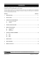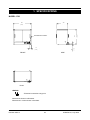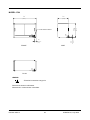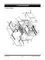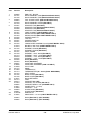
1
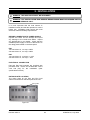
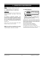
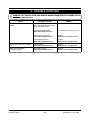
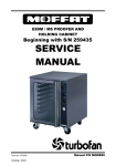
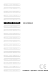
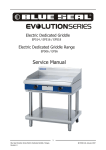
E83 / E84 FOOD WARMERS
SERVICE
MANUAL
Revision 6/3514
-1-
© Moffat Ltd, July 2006
WARNING: ALL INSTALLATION AND SERVICE REPAIR WORK MUST BE CARRIED OUT BY
QUALIFIED PERSONS ONLY.
Revision 6/3514
-2-
© Moffat Ltd, July 2006
CONTENTS
This manual is designed to take a more in depth look at the E83 and E84 food warmers for the purpose of
making the units more understandable to service people.
There are settings explained in this manual that should never require to be adjusted, but for completeness
and those special cases where these settings are required to change, this manual gives a full explanation
as to how, and what effects will result.
SECTION
PAGE NO.
1.
SPECIFICATIONS .............................................................................................................................. 5
2.
INSTALLATION .................................................................................................................................. 8
3.
OPERATION AND MAINTENANCE................................................................................................... 9
3.1
3.2
Description of Controls
Cleaning
4.
TROUBLE SHOOTING GUIDE........................................................................................................... 10
5.
SERVICE PROCEDURES .................................................................................................................. 11
5.1
5.2
5.3
6.
Fault Diagnosis
Access
Replacement
ELECTRICAL WIRING DIAGRAMS................................................................................................... 15
6.1
6.2
6..3
6.4
E83
E83-L
E84
E84-L
7.
SPARE PARTS ................................................................................................................................... 17
8.
PARTS DIAGRAM .............................................................................................................................. 18
9.
SERVICE CONTACTS........................................................................................................................ 20
IMPORTANT: MAKING ALTERATIONS MAY VOID WARRANTIES AND APPROVALS.
Revision 6/3514
-3-
© Moffat Ltd, July 2006
Revision 6/3514
-4-
© Moffat Ltd, July 2006
1. SPECIFICATIONS
MODEL: E83
595
595
356
356
1
515
515
ELECTRICAL ENTRY
E
1
(20.25)
(14.0)
(23.4)
E
35
35
(2.75)
FRONT
(1.4)
70 70
SIDE
1
E
PLAN
LEGEND
- Electrical connection entry point
Dimensions shown in millimetres.
Dimensions in inches shown in brackets.
Revision 6/3514
-5-
© Moffat Ltd, July 2006
MODEL: E84
795
795
356
356
1
515
515
ELECTRICAL ENTRY
E
1
(20.25)
(14.0)
(31.3)
E
(1.5)
FRONT
(1.4)
35
35
4070
SIDE
1
E
PLAN
LEGEND
- Electrical connection entry point
Dimensions shown in millimetres.
Dimensions in inches shown in brackets.
Revision 6/3514
-6-
© Moffat Ltd, July 2006
WARMER INTERNAL DIMENSIONS
E83
Width
Height
Depth
Warmer Volume
500mm / 19.7”
375mm / 14.75”
310mm / 12.2”
0.06m³ / 2.1ft³
E84
Width
Height
Depth
Warmer Volume
700mm / 27.5”
375mm / 14.75”
310mm / 12.2”
0.08m³ / 2.8ft³
OVEN RACK SIZE
E83
Width
Depth
493 mm / 19.5”
295 mm / 11.5”
E84
Width
Depth
693 mm / 27.25”
295 mm / 11.5”
ELECTRICAL SUPPLY SPECIFICATION
OPTIONS
E83
100-120 Volts A.C, 7.3 Amp, 0.8kW
220-240 Volts A.C, 3.4 Amp, 0.8kW
E84
100-120 Volts A.C, 10.0 Amp, 1.1kW
220-240 Volts A.C, 4.6 Amp, 1.1kW
ELECTRICAL PLUG SPECIFICATION
REQUIREMENTS
Australia
3-pin 250V 10A, AS/NZ 3112
Canada
3-pin 120V 15A, NEMA 5-15
New Zealand
3-pin 250V 10A, AS/NZ 3112
United Kingdom 3-pin 250V 13A fused, BS 1363A
Other Countries 3-pin 250V 10A minimum, type
to meet country standards
Revision 6/3514
-7-
© Moffat Ltd, July 2006
2. INSTALLATION
WARNING: THIS APPLIANCE MUST BE GROUNDED.
WARNING: ALL INSTALLATION AND SERVICE REPAIR WORK MUST BE CARRIED OUT BY
QUALIFIED PERSONS ONLY.
It is most important that the food warmer is
installed correctly and that the operation is correct
before use. Installation shall comply with local
electrical, health and safety requirements.
BEFORE CONNECTION TO POWER SUPPLY
Unpack and check unit for damage and report
any damage to the carrier and dealer. Report
any deficiencies to your dealer. Check that the
available power supply is correct to that shown on
the rating plate located on the base panel.
E83
100-120 Volts A.C, 7.3 Amp, 0.8kW
220-240 Volts A.C, 3.4 Amp, 0.8kW
E84
100-120 Volts A.C, 10.0 Amp, 1.1kW
220-240 Volts A.C, 4.6 Amp, 1.1kW
ELECTRICAL CONNECTION
E83 and E84 food warmers are supplied with
pre-fitted cords. Ensure unit is fitted with correct
cord and plug for the installation (refer
specifications section).
RATING PLATE LOCATION
The rating plate for the E83 and E84 food
warmers is located on the base plate of the unit.
Rating Plate
Figure 2.1
Revision 6/3514
-8-
© Moffat Ltd, July 2006
3. OPERATION & MAINTENANCE
NOTE: A full user’s operation manual is supplied with the product and can be used for further referencing
of installation, operation and service.
3.2 MAINTENANCE
3.1 DESCRIPTION OF CONTROLS
WARNING: ALWAYS TURN THE
POWER SUPPLY OFF BEFORE
CLEANING.
OPERATION
This unit is designed to heat pre-cooked food to
serving temperature, and keep it warm until
required.
IMPORTANT: THIS UNIT IS NOT
WATER PROOF.
DO NOT USE A WATER JET
SPRAY TO CLEAN EITHER INTERIOR
OR EXTERIOR OF THIS UNIT.
The element is thermostat controlled. Turn
thermostat dial clockwise to the desired level (or
on full until the desired temperature is reached,
then turn anti-clockwise until the pilot light goes
out). The thermometer shows the temperature in
the cabinet. The pilot light illuminates when the
element is on.
Remove doors - lift up out of bottom channel and
lower them out of top channel. (For full glass back
option, lift glass straight up). Remove racks after
doors have been removed.
Place food on the racks provided, with space
between to allow hot air to circulate.
Remove element guard by lifting out.
Clean with a damp cloth and detergent.
Re-assembly is the reverse of steps above.
NOTE: All models are supplied with a door
retaining bracket. When fitted, the two rear doors
cannot be opened. Remove if not needed.
Revision 6/3514
To replace door locate top of door into top
channel and lower door into bottom channel.
-9-
© Moffat Ltd, July 2006
4. TROUBLE SHOOTING
WARNING: ALL INSTALLATION AND SERVICE REPAIR WORK MUST BE CARRIED OUT BY
QUALIFIED PERSONS ONLY.
FAULT
THE WARMER DOES NOT OPERATE
POSSIBLE CAUSE
REMEDY
The mains isolating switch on the
wall, circuit breaker or fuses are
“off” at the power board.
Turn on.
Incorrect electrical supply.
(Refer fault diagnosis 5.1.1)
Ensure electrical supply correct.
Thermostat on unit faulty.
(Refer fault diagnosis 5.1.1)
Replace.
(Refer service section 5.3.2)
Element faulty (blown).
(Refer fault diagnosis 5.1.1)
Replace.
(Refer service section 5.3.4)
INDICATOR LIGHT NOT WORKING
Indicator faulty.
(Refer fault diagnosis 5.1.2)
Replace.
(Refer service section 5.3.1)
LAMP NOT WORKING
(-L MODELS ONLY)
Lamp faulty (blown).
(Refer fault diagnosis 5.1.3)
Replace.
(Refer service section 5.3.6)
Revision 6/3514
-10-
© Moffat Ltd, July 2006
5. SERVICE PROCEDURES
WARNING: ENSURE POWER SUPPLY IS SWITCHED OFF BEFORE SERVICING.
WARNING: ALL INSTALLATION AND SERVICE REPAIR WORK MUST BE CARRIED OUT BY
QUALIFIED PERSONS ONLY.
SECTION
5.1
FAULT DIAGNOSIS.............................................................................................................. 12
5.1.1
5.1.2
5.1.3
5.2
Warmer Does Not Operate.................................................................................. 12
Indicator Light Not Working ................................................................................. 12
Lamp Not Working (-L Models Only) ................................................................... 12
ACCESS................................................................................................................................ 12
5.2.1
5.3
PAGE NO.
Base Panel .......................................................................................................... 12
REPLACEMENT ................................................................................................................... 13
5.3.1
5.3.2
5.3.3
5.3.4
5.3.5
5.3.6
5.3.7
Revision 6/3514
Indicator Light ...................................................................................................... 13
Thermostat........................................................................................................... 13
Thermometer ....................................................................................................... 13
Element................................................................................................................ 13
Door Handle......................................................................................................... 14
Lamp .................................................................................................................... 14
Lamp Housing...................................................................................................... 14
-11-
© Moffat Ltd, July 2006
5.1 FAULT DIAGNOSIS
5.2 ACCESS
5.1.1 WARMER DOES NOT OPERATE
5.2.1 BASE PANEL
Incorrect electrical supply
1) Remove doors, racks and element guard.
Check that the voltage across phase and neutral
(L1 and L2) wires is the voltage as stated on the
unit’s electrical rating plate.
2) Turn unit onto its back and remove 10 screws
securing the base panel to the unit. The base
panel can now be removed.
If incorrect, check electrical connection of supply
wiring and / or check electrical supply.
Screws (10)
Thermostat faulty
Check voltage to terminal P on warmer
thermostat. If there is no voltage then check
wiring.
Set thermostat to 80°C. Check the voltage out of
terminal 1 on the thermostat. If there is no
voltage then the thermostat is faulty—replace.
If the voltage is correct then check all wiring to
element.
Figure 5.2.1
Element faulty (blown)
With the thermostat on and heating, check the
voltage across element terminals.
If the
voltage is correct then check the current draw of
the element. If there is no current draw then the
element is faulty—replace.
If there is no voltage to element terminals then
check voltage is being supplied to element form
terminal 1 on thermostat. If no voltage at 1 then
check for voltage at terminal P. If power to P
(and none to 1) then thermostat is faulty—
replace.
NOTE: Correct element current draw:
230V
E83:
E84:
3.5A ± 5%
4.8A ± 5%
110V
7.3A ± 5%
10.0A ± 5%
5.1.2 INDICATOR LIGHT NOT WORKING
Indicator faulty
With power to unit on, check the voltage across
the indicator terminals. If the voltage is correct
then indicator is faulty—replace.
If there is no voltage then check voltage is
being supplied from terminal 1 of thermostat
(refer Thermostat faulty).
5.1.3 LAMP NOT WORKING (-L MODELS)
Lamp faulty (blown)
With power to unit on, check voltage across lamp
terminals. If voltage is correct, lamp is faulty—
replace. If no voltage, check wiring.
Revision 6/3514
-12-
© Moffat Ltd, July 2006
5.3 REPLACEMENT
5.3.1 INDICATOR LIGHT
Two Screws
1) Remove base panel (refer 5.2.1).
2) Remove wires from indicator light, noting their
positions.
Figure 5.3.4
3) Push indicator light through from rear of
panel.
6) Transfer wires to new thermostat
re-assemble in reverse order.
4) Replace and re-assemble in reverse order.
and
5.3.3 THERMOMETER
1) Remove base panel (refer 5.2.1).
Indicator Light
2) Remove four screws at inside top of unit.
(Refer figure 5.3.2)
3) Remove black end cap, and slide off right
hand side panel.
4) Remove thermometer phial from phial bracket
located at inside top of unit.
Figure 5.3.1
5.3.2 THERMOSTAT
Thermometer
Phial
1) Remove base panel (refer 5.2.1).
Figure 5.3.5
2) Remove four screws at inside top of unit.
5) Push thermometer through from rear of panel,
whilst depressing the securing clips.
Thermometer
Clips
Four Screws
Figure 5.3.6
Figure 5.3.2
6) Replace and re-assemble in reverse order.
3) Remove black end cap, and slide off right
hand side panel.
5.3.4 ELEMENT
4) Remove thermostat phial from phial bracket
located at inside top of unit.
1) Remove base panel (refer 5.2.1).
2) Remove wires from element terminals, and
remove nuts securing element to unit.
Thermostat
Phial
Figure 5.3.3
5) Remove two screws securing thermostat to
front panel of unit, and withdraw thermostat.
Element Nut
Element
Terminals
Figure 5.3.7
Revision 6/3514
-13-
© Moffat Ltd, July 2006
3) Withdraw element from unit, by carefully unclipping from element support.
5.3.7 LAMP HOUSING (E83-L / E84-L
MODELS ONLY)
4) Replace and re-assemble in reverse order.
1) Remove four screws at inside top of unit, on
both the left and right hand sides.
5.3.5 DOOR HANDLE
1) Remove door from unit.
2) Remove two screws securing door handle to
door.
Four Screws
3) Replace and re-assemble in reverse order,
ensuring that a fibre washer is placed
between each screw and the door glass.
Figure 5.3.10
2) Remove black end caps, and remove top
cover from unit.
3) Remove wires from the lamp
terminals, noting their positions.
Two Screws
housing
Lamp Terminals
Figure 5.3.8
Figure 5.3.11
4) Push lamp housing through bracket from top
of unit. Replace and re-assemble in reverse
order.
5.3.6 LAMP (E83-L / E84-L MODELS ONLY)
1) Prise off lamp cover from lamp housing, located at top of unit.
Lamp Cover
Figure 5.3.9
2) Replace lamp, and re-secure lamp cover.
Revision 6/3514
-14-
© Moffat Ltd, July 2006
6. ELECTRICAL WIRING DIAGRAM
6.1 E83
6.2 E83 - L
Revision 6/3514
-15-
© Moffat Ltd, July 2006
6.3 E84
6.4 E84 - L
Revision 6/3514
-16-
© Moffat Ltd, July 2006
7. SPARE PARTS
PART NO
DESCRIPTION
020960
020961
020962
020963
018178K
020964
020965
021109
022103
021110
022102
011980
021112
021113
013528
021342
014218
014219
21114
20966
21102
21103
Door Glass (E83 only)
Door Glass (E84 only)
Glass Back Panel (E83 only)
Glass Back Panel (E84 only)
Door Handle Kit
Rack (E83 only)
Rack (E84 only)
Element - 240V 800W (E83 only)
Element - 110V 800W (E83 only)
Element - 240V 1100W (E84 only)
Element - 110V 1100W (E84 only)
Thermostat
Knob
Thermometer
Neon Indicator
Lamp Holder Assembly (Light Models Only)
Bulb E14 25W 240V (Light Models Only)
Bulb E14 15W 115V (Light Models Only)
Foot
End cap
Element Guard (E83 only)
Element Guard (E84 only)
Revision 6/3514
-17-
© Moffat Ltd, July 2006
8. PARTS DIAGRAMS
22
19
21
20
17
23
29
24
8
2
1
3
10
11
9
4
29
8
12
25
6
5
29
13
15
14
16
9
7
11
1
18
4
10
26
27
28
8.1 MAIN ASSEMBLY
Revision 6/3514
-18-
© Moffat Ltd, July 2006
Pos
Part No.
Description
1
2
020966
021107
021108
020962
020963
021099
021100
021087
021089
021088
021090
021757
021758
021759
021098
021085
021097
021091
021342
014218
014219
021102
021103
021101
021109
021110
022103
022102
021092
021093
002597
015098
013528
021112
011980
021113
021104
021105
021106
010547
021114
002414
017453
025855
012877
012289
020960
020961
018178K
013062
END CAP - BLACK
DOOR CHANNEL TRIM (E83 SOLID BACK ONLY)
DOOR CHANNEL TRIM (E84 SOLID BACK ONLY)
FULL GLASS PANEL (E83 SOLID BACK ONLY)
FULL GLASS PANEL (E84 SOLID BACK ONLY)
DOOR CHANNEL UPPER (E83 ONLY)
DOOR CHANNEL UPPER (E84 ONLY)
WRAPPER TOP (E83 ONLY)
WRAPPER TOP (E83 SOLID BACK ONLY)
WRAPPER TOP (E84 ONLY)
WRAPPER TOP (E84 SOLID BACK ONLY)
LAMP CHANNEL (LIGHT MODEL ONLY)
WIRING COVER (E83 LIGHT MODEL ONLY)
WIRING COVER (E84 LIGHT MODEL ONLY)
CORNER POST LH
TOP RAIL
CORNER POST RH
WRAPPER SIDE
LAMPHOLDER ASSEMBLY 240V (LIGHT MODEL ONLY)
BULB E14 25W 240V (LIGHT MODEL ONLY)
BULB E14 15W 125V (LIGHT MODEL ONLY)
ELEMENT GUARD (E83 ONLY)
ELEMENT GUARD (E84 ONLY)
PHIAL GUARD
ELEMENT - 240V -800W (E83 ONLY)
ELEMENT - 240V -1100W (E84 ONLY)
ELEMENT - 110V -800W (E83 ONLY)
ELEMENT - 110V -1100W (E84 ONLY)
BASE (E83 ONLY)
BASE (E84 ONLY)
CORD GRIP GROMMET
CORD GRIP GROMMET (CAN / UK ONLY)
PILOT LAMP
KNOB
THERMOSTAT
THERMOMETER (20 - 120ºC) (DUAL MARKINGS)
HEAT SHIELD
BASE COVER (E83 ONLY)
BASE COVER (E84 ONLY)
DOOR RETAINER
FOOT
CORDSET (AU / NZ)
CORDSET 13A FUSED (UK ONLY)
CORDSET NEMA 5-15P (CANADA ONLY)
POWER FLEX - 7.5 Amp
CORDSET - 110V
GLASS DOOR (E83 ONLY)
GLASS DOOR (E84 ONLY)
HANDLE KIT
SNAP BUSH – 12.7mm (LIGHT MODEL ONLY)
020964
020965
RACK (E83 ONLY) (NOT SHOWN)
RACK (E84 ONLY) (NOT SHOWN)
3
4
5
6
7
8
9
10
11
12
13
14
15
16
17
18
19
20
21
22
23
24
25
26
27
28
29
Revision 6/3514
-19-
© Moffat Ltd, July 2006
9. SERVICE CONTACTS
AUSTRALIA
VICTORIA - MOFFAT PTY
HEAD OFFICE AND MAIN WAREHOUSE
740 Springvale Road
Mulgrave VIC 3170
Spare Parts Department
NEW SOUTH WALES - MOFFAT PTY
Unit 8/142 James Ruse Drive
Rosehill NSW 2142
Spare Parts
Tel (03) 9518 3888
Fax (03) 9518 3838
Free Call 1800 337 963
Fax (03) 9518 3895
Free Call 1800 337 963
Fax (03) 9518 3895
QUEENSLAND - MOFFAT PTY
30 Prosperity Place
Geebung QLD 4034
Spare Parts
Free Call 1800 337 963
Fax (03) 9518 3895
SOUTH AUSTRALIA - MOFFAT PTY
Suite 8/71 Fullarton Rd
Kent Town SA 5067
Spare Parts
Tel (08) 8431 0522
Free Call 1800 337 963
WESTERN AUSTRALIA - MOFFAT PTY
PO Box 689
Joondalup Business Centre WA 6027
Spare Parts
Tel (08) 9305 8855
Free Call 1800 337 963
NATIONAL COVERAGE FOR 24 HOUR SERVICE OR MAINTENANCE DIAL
FREE CALL 1800 622 216 (AUSTRALIA ONLY)
CANADA
Serve Canada
22 Ashwarren Road
Downview
Ontario M3J1Z5
Free Call: 800 263 1455
Ph: (416) 631 0601
Fax: (416) 631 0315
NEW ZEALAND
CHRISTCHURCH - MOFFAT LTD
16 Osborne St
PO Box 10-001
Christchurch
Spare Parts
Free Call 0800 Moffat
(0800 663 328)
Tel (03) 389 1007
Fax (03) 389 1276
AUCKLAND - MOFFAT LTD
4 Waipuna Road
Mt Wellington
Auckland
Spare Parts
Revision 6/3514
Tel (09) 574 3150
Fax (09) 574 3159
Free Call 0800 Moffat
(0800 663 328)
-20-
© Moffat Ltd, July 2006
UNITED KINGDOM
BLUESEAL LTD
Units 6-7 Mount St Business Park
Nechells
Birmingham B7 5QU
England
Tel 0121-327 5575
Fax 0121-327 9711
UNITED STATES OF AMERICA
MOFFAT INC.
3765 Champion Blvd
Winston-Salem
NC27115
Tel 1-800-551 8795
Fax 336 661 9546
NATIONAL COVERAGE FOR SERVICE OR MAINTENANCE DIAL
FREE CALL 1800 551 8795 (USA ONLY)
Revision 6/3514
-21-
© Moffat Ltd, July 2006