1
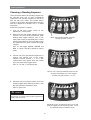
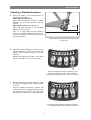
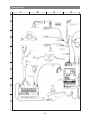
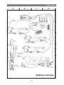
SERVICE MANUAL US VS Seat system for electric wheelchair How to contact Permobil Head Office of the Permobil group Produced and published by Permobil AB, Sweden Edition 2, 2009-09 Item No.: 205217-US-0 Table of Contents Table of Contents Introduction ............................................................................................................ 5 Technical support................................................................................................ 5 Spares and accessories ..................................................................................... 5 Disposal .............................................................................................................. 5 Guarantee & service ........................................................................................... 5 Maintenance ....................................................................................................... 5 Product approval................................................................................................. 5 Initial adjustments ................................................................................................. 6 Selection of seat elevation sequence ................................................................. 6 Adjusting the seat length. ................................................................................... 8 Leg rest extension............................................................................................. 11 Foot plate.......................................................................................................... 12 Knee support .................................................................................................... 14 Arm rest ............................................................................................................ 16 Chest support ................................................................................................... 16 Head rest .......................................................................................................... 17 Trunk support.................................................................................................... 18 Lumbar support................................................................................................. 18 Repairs.................................................................................................................. 19 Replacing the general module.......................................................................... 19 Replacing the elevation actuator ...................................................................... 20 Replacing the back rest angle actuator ............................................................ 22 Replacing the leg rest angle actuator............................................................... 24 Replacing the seat angle actuator .................................................................... 25 Replacing the parallel stays ............................................................................. 26 Replacing the crush protection switch .............................................................. 26 Replacing the knee support strap..................................................................... 28 Replacing the leg rest strap.............................................................................. 29 Replacing the strap for the sliding back ......................................................... 30 Cabling overview ................................................................................................ 32 Index...................................................................................................................... 34 4 Introduction Introduction The Service Manual is intended for technical personnel who maintain and repair power wheelchairs. It is important that anyone who performs maintenance and repairs described in this manual reads and understands the content of this manual so that the work is performed professionally. Always state the chassis number when contacting Permobil to ensure that the correct information is provided. All information, pictures, illustrations and specifications are based upon the product information that was available at the time that these instructions were printed. Pictures and illustrations that are found in these instructions are representative examples and not intended to be exact depictions of the various parts of the wheelchair. We reserve the right to make changes to the product without prior notice. Technical Support In the event of technical problems, you should contact your dealer, or Permobil Inc. USA at 800-736-0925. Spare parts Spare parts must be ordered through your dealer. Warranties Contact your dealer or Permobil Inc. USA for information about the warranties for this chair. Maintenance See the information in the Owner’s Manual. 5 Initial adjustments Choosing a Standing Sequence The ICS System allows the standing sequence to be selected from one of three pre-defined sequences. The standing sequence is chosen to best suit the user’s needs. The system always requires a seat height adjustment when changing from one sequence to another. This is a safety precaution. 1 Follow the instructions carefully. 2. Move and hold the toggle switches towards position 5 and 7 on the ICS Switchbox, while holding these toggle switches, turn on the main power switch on the wheelchair’s control panel (or Input Device). Once all LEDs on the ICS Switchbox turn green, release the toggle switches. 3 4 8 6 5 1. Turn off the main power switch on the wheelchair’s control panel. 2 7 Move and hold the toggles switches towards position 5 and 7. LED ”H” will toggle between GREEN and RED to signify Standing Sequence Select mode. 3. Choose one of the pre-defined sequences by moving and holding one of the toggle switches towards position 1, 2 or 3. The symbol above turns green, when the symbol turns red, release the toggle switch. 1 5 2 3 6 7 LED ”A”, ”B” and ”C” will glow green. 4 8 Choose one of the pre-defined sequences by moving and holding one of the toggles switches towards position 1, 2 or 3. 4. Stand the seat to its upper position, move and hold the toggle switch towards position 1 until the Stand Actuator movement stops. LED ”H” glows red. 1 2 3 4 WARNING 5 Watch the footplate as the chair is stood, raise the Seat Elevator as needed to prevent the footplate from colliding with the ground. 6 7 8 Stand the seat to its upper position, move and hold the toggle switch towards position 1 until the Stand Actuator movement stops. 6 Initial adjustments Choosing a Standing Sequence 5. Adjust the height of the Seat Elevator for proper legrest clearance. Adjusting with empty seat: Adjust the Seat Elevator so there is 10mm. between the Footplate Wheels and the ground. Adjusting with the user in the seat: Adjust the Seat Elevator so the Footplate Wheels touch the ground. 10mm. LED ”H” is green when the Seat Height is within an acceptable height range, if LED ”H” is red, the settings cannot be stored. (Lower the Seat Elevator.) With empty seat, adjust the Seat Elevator so there is 10mm between the Footplate Wheels and the ground. 6. Store the selected Sequence and the correct Standing Height by moving and holding the toggle switch towards position 8 for two seconds. Release the toggle switch after a short beep sounds and LEDs ”G” and ”H” turn green. 1 5 2 3 6 7 4 8 Store the selected Sequence and the correct Standing Height by moving and holding the toggle switch towards position 8 for two seconds. 7. Exit the Standing Sequence Selection mode by moving the toggle switch towards position ”4” once. Test the Standing Sequence. Confirm that everything works as expected. Make sure that the footplate wheels have the appropriate clearance when the chair is completely stood. 4 1 5 2 3 6 7 8 Exit the Standing Sequence Selection mode by moving the toggle switch towards position ”4”. 7 Initial adjustments Adjusting the seat depth The seat depth can be adjusted to fit different users. On Senior seats depth can be adjusted between 18”-22”. Where greater seat depth is required, a seat extender can be fitted, allowing for adjustments of up to 24”. On Junior seats depth can be adjusted between 16”-20”. Adjustment of seat depth is performed by moving the back rest in 1” steps. To set the seat depth, see pages 7-8. To mount the seat extender, see below. Remove the plastic cover from the end of the seat frame. WARNING When adjusting the seat depth, follow the instructions on pages 7-8 exactly. A faulty adjustment could cause serious damage to the seat. Installing the seat extender. Mounting a seat extender on a Senior seat allows the depth to be increased by a further 2”. The seat depth can then be adjusted from 18” to 24”. 1. Remove the two plastic covers in the seat frame ends, left and right, see photo above. 2. Mount the seat extender by inserting it in the back edge of the seat frame, see photo on right. 3. Screw the extender into place using the two screws supplied – see photo on right. Insert the seat extender into the rear edge of the seat frame and mount it with two screws from below. NOTE If seat extender is mounted, the seat bracket has to be remounted in the correct position, see fig. 1 2 1 2 Seat without seat extender is mounted in the front hole pattern(2). When extender is mounted the seat bracket has to be moved to the rear hole pattern(1). 8 Initial adjustments Adjusting the seat depth Back rest bearing bracket, right Back rest bearing bracket, left Parallel stays for arm rests Fixing for back rest actuator Seat depth Adult Junior A: B: C: D: E: F: G: 1: 2: A: B: C: 18”. 19”. 20”. 21”. 22”. 23”. * 24”. * 16”. 16 3/4”. 18”. 19”. 20”. *Seat extension The seat depth can be adjusted from 18” - 24” on VS Senior and from 16”-20” on VS Junior. 9 Initial adjustments Adjusting the seat depth WARNING Adjustment of seat depth must only be carried out by authorised personnel. A faulty adjustment could cause serious damage to the seat. When making the adjustment, follow the instructions exactly. The letters on the back rest bearing brackets, the front fixing on the elevation actuator, the parallel stay and the rear seat plate must agree. Faulty adjustment could cause serious damage to the seat. 1. Remove the seat plates, mounted with four screws, see photo. 2. Remove the position screw (1) on the parallel stay for the arm rest, see photo below. The seat plates are mounted with four screws. 3. Remove the forward fixing on the back rest actuator (2), mounted with three screws, see photo below. 4. Remove the bearing brackets (3) for the back rest, mounted with two screws each from below. Refix them in the position which gives the required seat depth, see photo below. If necessary, mount the seat extender, see p. 7. 5. Remount the front fixing (2) on the elevation actuator, mounting it in the position with the same letter as the bearing brackets, see photo below. 6. Mount the position screw (1) in the parallel stay for the arm rest. Mount the position screw in the position with the same letter as the bearing brackets and the elevation actuator fixing, see photo below. Mount the rear seat plate in the position with the same letter as the bearing brackets, elevation actuator and parallel stay. In this example, position D. 7. Remount the seat plates. Mount the rear seat plate in the position with the same letter as the bearing brackets, elevation actuator and parallel stay, see photo on right. 3 2 1 3 2 1 3 The position screw on the parallel stay, the forward fixing of the elevation actuator and the back rest bearing brackets are all mounted in a position with the same letter. In this example, position D. 10 Initial adjustments Adjustment of leg rest extension When the seat is raised from sitting to standing position, the leg rest is extended in order to improve the user’s comfort. The leg rest extension can be set to three different positions. Adjustment is done by moving the roller which the leg rest strap runs over. The roller (1) is mounted under the seat, behind the leg rest, see photo below. 1. Remove the seat plates, mounted with four screws, see photo on right. The seat plates are mounted with four screws. 2. Remove the screw (1) holding the roller, see photo on right. 3. Release the two screws (2) holding the clamp for the leg rest tape. This is situated behind the leg rest under the middle of the seat, see photo below. 4. Move the roller to the desired position. To increase the leg rest extension, move the roller down. To reduce the leg rest extension, move the roller up. 1 5. Remount the roller with the screw (1) in the desired position, see photo on right. To increase the leg rest extension, move the roller down. To reduce the leg rest extension, move the roller up. 6. With the seat in sitting position and the leg rest at its shortest, push up the leg rest to its highest position, pull on the tape and lock it in position with the clamp and the two screws (2) see photo on right. NOTE The leg rest must be pushed up into its top position, as otherwise the seat could be damaged and the user inujured. 2 The lock for the leg rest tape is situated on the rear of the leg rest under the seat. 11 Initial adjustments Adjustment of foot plate Angle The foot plate angle can be adjusted by screwing the nuts (2) on the foot plate adjustment screws in or out, see photo on right.. 1 NOTE After adjustment always carefully screw up the two nuts to lock the adjustment. 2 Height 1. Releast the two locking screws (1) on the foot plate, see photo. Leg rest seen from behind. 2. Adjust the foot plate to the desired height. 3. Retighten the locking screws. 4. Check that the support wheels are about 10 mm lower than the leg support, and adjust if necessary, see below. Adjusting support wheel height If the height of the foot plate on seats without standing operation is greatly changed, it may be necessary to adjust the height of the support wheels. 1. Release the fixing screws (3) on the support wheels, see photo below. Max. 15mm. 2. Adjust the support wheels to the desired height. Check that the support wheels are min. 10 mm. lower than the leg rest. With this type of support wheels, also check that the support wheels are max. 15 mm. lower than the footplate. 3. Retighten the support wheel fixing screws. Env. 10mm. NOTE On seats with the type of support wheels shown in the photos above, check that the support wheels are max. 15 mm. lower than the footplate. If setting with greater disance is needed, a nother type of support wheels are needed, see photo below to the right. 3 Support wheel fixing on seat without standing operation function. Support wheel fixing on seat equipped for standing operation. 12 Initial adjustments Adjustment of foot plate Reversing the foot plate fixing If further adjustment of foot plate height is necessary, it is possible to reverse the fixing, which will enable the foot plate to be set higher up. 1. Remove the support wheels. On seats with standing operation they are mounted with two screws on either side of the leg rest, see photo at the bottom on previous page. On seats without standing operation they are mounted on the rear edge of the foot plate, see photos at the bottom on previous page. Fixing screws for knee support and foot plate. 2. Remove the knee support, mounted with one screw, see photo on right. 3. Remove the six screws holding the foot plate, see photo on right. The foot plate is mounted with 6 screws. 4. Release the two locking screws on the height adjustment device, see photo on right. 5. Remove and turn the fixing over, replacing the foot plate and knee support in the reverse order. Adjustment of foot plate angle. 13 Initial adjustments Adjustment of knee support Angle of knee support strap Adjust the angle of the knee support strap in order to provide as smooth a fit as possible when using the elevation function. Adjust the roller so the angle of the strap with the horizontal is equally large downwards in the sitting position as it is upwards in the standing position. 1. Check and visually compare the angle of the tape with the horizontal for standing and sitting positions. Angle of knee support strap in sitting position. Angle of knee support strap in standing position. 2. If the angle of the strap needs adjusting, release the fixing on the roller, mounted with four screws, see photo on right. 3. The roller fixing can be moved 5 steps at 20 mm intervals. If the strap angle is too great in the sitting position, move the roller upwards. If the strap angle is too great in the standing position, move the roller down. 4. Mount the roller fixing in a suitable position and replace the four screws, see photo. 5. Check and visually compare the angle of the strap with the horizontal for standing and sitting positions. The roller is mounted with four screws and can be moved in 5 steps at 20 mm intervals. 14 Initial adjustments Adjustment of knee support Positioning 1. Adjust the knee support in sitting position to a location approx. 3-4 cm in front of the legs. Carry out adjustment with the knob (1) on the rear edge of the seat frame, see photo on right. 2. Carefully test all the seat’s functions and check that the positioning of the knee support is comfortable in all positions. 1 Knob for adjusting the knee support’s position. Height 1. Release the knee support’s locking knob (2), see photo on right. 2. Move the continuous position screw (3) on the leg rest to a suitable position, see photo on right. 3. Tighten the knee support locking knob (2). 2 3 NOTE The knee support must always be in contact with the position screw when the locking knob is turned. 4. Carefully test all the seat’s functions and check that the height of the knee support is comfortable in all positions. Adjusting the knee support. 15 Initial adjustments Adjustment of arm rest Height/angle 1. Release the two nuts on the inside of the arm rest, see photo on right. 2. Adjust the arm rest for height and angle.3. Tighten the two nuts. Adjustment of chest support Depth 1. Unscrew the two nuts on the inside of the arm rest, see photo. 2. Move the fixing on the chest support until it reaches a suitable depth. The depth can be adjusted at intervals of 1”. 3. Secure the fixing with the two nuts without tightening them. 4. Adjust the height and angle of the arm rest and tighten the two nuts. Adjustment of arm rest and chest support. Height 1. Release the Allen screws (1) on the locking ring on either side of the chest support, see photo. 2. Adjust the chest support to a suitable height, but never so high that the fixing is not visible at the lower edge of the sleeve (2), see photo. 3. Tighten the Allen screws on the locking ring 1 2 WARNING Adjustment of chest support. Never adjust the height so far that the chest support fixing is not visible at the lower edge of the sleeve. 16 Initial adjustment Adjustment of head rest (accessory) Adjustment of height 1. Release the knob (1) on the rear of the back rest, see photo. 2. Adjust head rest height as required. 3. Tighten the knob (1). Adjustment forwards/backwards 1. Release the knob (2) on the rear of the back rest, see photo. 2. Adjust the head rest forward/backwards as required. 3. Tighten the knob (2). 1 2 Adjustment of head rest. Adjustment of head rest (accessory) The head rest has extended adjustment capability in order to give the user optimum comfort, see photo on right. The head rest is easy to remove/remount while preserving the same settings. Removing 1. Release the knob (3) on the rear of the back rest, see photo. 2. Detach the head rest by lifting it straight up. Mounting Mount in reverse order. Head rest with wide adjustment capability. Adjustment of height/depth 1. Release the knob (1) on the rear of the back rest, see photo below. 2. Adjust head rest height/depth as required. 3. Tighten the knob (1). Adjustment of angle 1. Release the knob (2) on the rear of the head rest, see photo. 2. Adjust head rest angle as required. 3. Tighten the knob (2). 1 2 3 Adjustment of head rest. 17 Initial adjustments Adjustment of trunk support (accessory) Height 1. Release the knob on the rear of the back rest, see photo. 2. Adjust the trunk support to the desired height. 3. Retighten the knob. Adjusting the trunk support. Adjustment of lumbar support Height/depth 1. Remove the back cushion. 2. Adjust the lumbar support as required. 3. Replace the back cushion. Adjusting the trunk support. 18 Repairs Repairs Replacing the General Module The elevation device’s general module is located under the crush protection cover. Removal 1. If possible, raise the seat to standing position, otherwise lower the seat forwards, see section on “replacement of elevation actuator“ on page 20. 2. Remove the crush protection cover, mounted with four screws, see photo on right. Note how the cover is fitted with screw, washer, spacer and spring at the rear edge for use in remounting it. The crush protection cover is mounted with four screws. 3. Detach the two contacts on the general module and the contact on the third cable in the contact device on the underside of the seat. 4. Remove the general module, mounted with two screws, see photo on right. Installation Mount in reverse order. Note how the crush protection cover is mounted with screw, washer, spacer and spring at the rear edge, see photo below. Check the crush protection function after mounting. The general module is mounted with two screws. General module. Mounting of crush protection cover 19 Repairs Repairs Replacing the gas spring On some models of the VS a servokit is mounted. Below describes the proceedure of changing the gasspring on the servokit. Removal 1. With the seat in sitting position, raise the seat lift to improve access from beneath. 2. Remove the front fixing screw from the elevation actuator, see photo on right. Front fixing screw on actuator. WARNING The seat raises towards standing position by it self when the elevation actuator is removed. Push the back rest backwards as the actuator is removed, see fig. When removing the actuators front end, carefully place the actuator on the wheelchairs chassi. The new actuator is calibrated at the factory and its piston rod must not be turned while the actuator is loose. If this happens, the actuator will need to be calibrated and this requires special equipment. Detailed information on calibration is given in the technical manual for the ICS control system. Before removing the actuator it´s recomendet that the piston is taped up with the rest of the actuator to prevent rotation of the piston. Push the back rest backwards as the actuator is removed 3. Carefully lower the seat forwards, see photo on right. Carefully lower the seat forwards. 20 Repairs 3. Remove the gas spring, it’s fitted with two quick fasteners The gas spring fasteners. The gas spring front fastener. Gas spring with fasteners. 21 Repairs Repairs Replacing the elevation actuator Removal 1. With the seat in sitting position, raise the seat lift to improve access from beneath. 2. Remove the front fixing screw from the actuator, see photo on right. Front fixing screw on actuator. 3. Carefully lower the seat forwards, see photo on right. Carefully lower the seat forwards. 4. Remove the crush protection cover, mounted with four screws, see photo on right. The crush protection cover is mounted with four screws. 22 Repairs Repairs 5. Separate the actuator cables at the contacts on the cables. See photo on right. The electrical connections to the actuator are separated at the contacts on the cables. 6. Remove the rear fixing screw on the actuator, see photo on right. Mounting Mount in reverse order. WARNING The new actuator is calibrated at the factory and its piston rod must not be turned while the actuator is loose. If this happens, the actuator will need to be calibrated and this requires special equipment. Detailed information on calibration is given in the technical manual for the ICS control system. Before removing the actuator it is recommended that the piston rod is fixed into position by taping it to the actuator housing. Rear fixing screw of the actuator. 23 Repairs Repairs Replacing the back rest angle actuator Removal 1. Remove the actuator, mounted with two screws, see photo on right. 2. Separate the actuator’s cables at the contact on the cables, if necessary cutting the bundle strip. Installation The back rest angle actuator is mounted with two screws. Mount in reverse order. Use thread lock on mounting screws. WARNING The new actuator is calibrated at the factory and its piston rod must not be turned while the actuator is loose. If this happens, the actuator will need to be calibrated and this requires special equipment. Detailed information on calibration is given in the technical manual for the ICS control system. Before removing the actuator it is recommended that the piston rod is fixed into position by taping it to the actuator housing. Replacing the leg rest angle actuator Removal 1. Raise the seat to the standing position. 2. Remove the actuator, mounted with two screws, see photo on right. 3. Separate the actuator’s cables at the contact on the cables, if necessary cutting the bundle strip. Installation Mount in reverse order. Use thread lock on mounting screws. The back rest angle actuator is mounted with two screws. WARNING The new actuator is calibrated at the factory and its piston rod must not be turned while the actuator is loose. If this happens, the actuator will need to be calibrated and this requires special equipment. Detailed information on calibration is given in the technical manual for the ICS control system. Before removing the actuator it is recommended that the piston rod is fixed into position by taping it to the actuator housing. 24 Repairs Repairs Replacing the seat angle actuator Removal 1. Raise the seat lift to its highest position 2. Extend the leg rest to its maximum position. 3. Remove the seat plates, mounted with four screws, see photo on right. The seat plates are mounted with four screws. 4. Remove the lower fixing on the actuator, see photo on right. 5. Separate the actuator cables at the contact on the cables. If necessary, cut the bundle strip. Lower fixing for seat angle actuator. 6. Remove the upper fixing on the actuator, see photo on right. Installation Mount in reverse order. WARNING The new actuator is calibrated at the factory and its piston rod must not be turned while the actuator is loose. If this happens, the actuator will need to be calibrated and this requires special equipment. Detailed information on calibration is given in the technical manual for the ICS control system. Before removing the actuator it is recommended that the piston rod is fixed into position by taping it to the actuator housing. Upper fixing for seat angle actuator. 25 Repairs Repairs Replacing the parallel stays The seat has two parallel stays which hold the arm rests in the correct position. Upper parallel stay With the seat in the sitting position, remove the upper parallel stay, mounted with two screws, see photo on right. WARNING Lower parallel stay on arm rest. Always take great care when removing the parallel stays, as this will make the arm rests mobile and requiring other means of support. Lower parallel stays 1. Raise the seat halfway to the standing position. 2. Remove the parallel stay, mounted with two screws, see photo on right. WARNING Always take great care when removing the parallel stays, as this will make the arm rests mobile and requiring other means of support. Installation Mount in reverse order. Upper parallel stay on arm rest. Replacing the crush protection switch The crush protection switch is under the crush protection cover. Removal 1. If possible, raise the seat to standing position, otherwise lower the seat forwards, see section on “replacement of elevation actuator” on page 20. 2. Remove the crush protection cover, mounted with four screws, see photo on right. Note how the cover is fitted with screw, washer, spacer and spring at the rear edge for use in remounting it. The crush protection cover is mounted with four screws. 26 Repairs Repairs 3. Remove the crush protection switch, mounted with its accompanying nut and washer, see photo. 4. Remove the cable from the crush protection switch. Note the cable’s position for use in remounting. The crush protection switch is mounted with its accompanying nut and washer. Installation Mount in reverse order. The crush protection cover mounting at the rear edge, with screw, washer, spacer and spring, can be seen on the photo at the bottom of page 26. Check the crush protections function after mounting. 22mm. Adjust the witch to correct height. Crush protection switch 27 Repairs Repairs Replacing the knee support strap Removal 1. Raise the seat lift to the standing position. 2. Remove the crush protection cover, mounted with four screws, see photo on right. Note how the cover is fitted with screw, washer, spacer and spring at the rear edge for use in remounting it. The crush protection cover is mounted with four screws. NOTE Before removal, check the mounting of the strap for use in remounting it. 3. Remove the screw (1) holding the strap on the seat frame, see photo on right. 1 2 4. Remove the screw (3) holding the strap on the knee support, see photo on right. Mounting The knee support strap has an eyelet at each end. 1. Screw the strap in place with the screw (3) by the knee support, see photo. 2. Pull the strap under the roller (2), over the leg support and straight in towards the fixing buckle. Mounting of knee support strap. 3. Thread the strap through the fixing buckle from underneath. 4. Screw the strap in place with the screw (1) in the seat frame. NOTE Check that the strap is not twisted or damaged. 5. Remount the crush protection cover, noting how the cover is fitted with spacer, spring, washer and screw at the rear edge, see photo on right. NOTE Check the crush protection cover’s function after mounting. Mounting of crush protection cover 28 3 Repairs Repairs Replacing the leg rest strap Removal 1. With the seat in sitting position, raise the seat lift to improve access from beneath. 2. Remove the seat plates, mounted with four screws, see photo on right. The seat plates are mounted with four screws. 3. Remove the knee support by unscrewing its fixing screw (1), see photo on right. 4. Release the two screws (2) on the rear fixing of the strap, see photo below. WARNING Take great care when releasing the rear fixing of the tape, as the leg support will now be completely loose. Hold it so it does not fall on the floor. 5. Remove the strap from the leg support by unscrewing screw (3), see photo below right. 1 Installation Adjusting the knee support. Mount in reverse order. 3 2 Fixing for leg support strap on leg support. The lock for the leg rest strap is situated on the rear of the leg rest. 29 Repairs Repairs Replacing the strap for the sliding back (optional) Removal 1. Run the back rest function so that the back rest inclines backwards slightly. 2. Remove the circlip on the right side of the lower strap bracket, see photo. Circlip on the right side of the lower strap bracket. 3. With a firm grip, carefully lift the back rest up until the strap slackens, and pull out the cotter, see photo. Carefully lower the back rest to its lowest position. WARNING Take great care when loosening the cotter, and lower the back rest carefully to its lowest position. Note there is a risk of crushing between the back rest and its joint. Carefully lift the back rest up until the strap slackens, and pull out the cotter. 4. Remove the upper bracket of the strap, which is attached to the front of the back rest with two screws, see photo. The upper bracket of the strap is attached with two screws. 30 Repairs Repairs Replacing the strap for the sliding back (optional) Installation 1. Fit the new strap and bracket to the back rest, see photo. Do not pull the screws out fully. Fit the new strap and bracket to the back rest. 2. With a firm grip, carefully lift the back rest up until the strap reaches the lower bracket and fit the cotter in the central position of the bracket, through the loop of the strap, see photo. Carefully lower the back rest so that the strap is tensioned. For particular requirements, the sliding function can be increased or decreased by fitting the cotter in the outer or inner holes instead. WARNING Take great care when installing in a different position than standard, as this can lead to an increased risk of crushing. This is particularly the case if the seat is equipped with a trunk support. Carefully lift the back rest up until the strap reaches the lower bracket and fit the cotter. 3. Refit the circlip on the right side of the lower strap bracket , see photo. Refit the circlip on the right side of the lower strap bracket. 31 Cabling overview 1 2 3 A B C D E F 32 4 Cabling overview 5 6 7 8 A B C D E F Cabling overview 33 Index Index A K Arm rest ............................................ 16 Knee support .................................... 14 Knee support strap .......................... 18 B Back rest angle actuator ..................22 L C Leg rest angle actuator .................... 24 Leg rest extension ............................ 11 Leg rest strap .................................... 29 Lumbar support ................................ 18 Cabling overview .............................. 32 Chest support .................................... 16 Crush protection switch .................. 26 P E Parallel stays Elevation actuator ............................ 20 S F Foot plate .......................................... 12 Seat angle actuator .......................... 25 Seat elevation sequence .................... 6 Seat length ........................................ 8 G T General module ................................ 19 .................................. 26 Trunk support ....................................18 H W Head rest .......................................... 12 Wiring diagram ................................ 32 34 Item No.: 205217-US-0