1
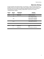
Installation/Operation Manual with Service Replacement Parts
Undercounter
High Temperature
Dishwasher
Models:
351HT
351HT
Machine Serial No.
Issue Date: 6.15.15
Manual P/N 0512864 rev. F
For machines beginning with S/N W090217876 and above
3765 Champion Blvd.
Winston-Salem, NC 27105
336/661-1992 Fax: 336/661-1660
Toll-free: 800/ 858-4477
2674 N. Service Road, Jordan Station
Ontario, Canada L0R 1S0
905/562-4195 Fax: 905/562-4618
Toll-free: 800/ 263-5798
Printed in the USA
For future reference, record your dishwasher information in the box below.
Model Number__________________________ Serial Number_______________________
Voltage________________Hertz_____________ Phase__________________
Service Agent __________________________________ Tel:______________________
Parts Distributor _________________________________ Tel:______________________
National Service Department
In Canada:
Toll-free: 800/ 263-5798
Tel:
905/ 562-4195
Fax:
905/ 562-4618
email: [email protected]
In the USA:
Toll-free: 800/ 858-4477
Tel:
336/ 661-1992
Fax: 336/ 661-1660
email: [email protected]
ATTENTION:
The model no., serial no., voltage, Hz
and phase are needed to identify your
machine and to answer questions.
The machine data plate is located
on the lower front panel.
Please have this information ready
if you call for service assistance.
The USGBC and the CaGBC Member Logos are trademarks owned by the U.S. Green Building Council and The Canadian Green Building Council,
respectively, and are used by permission. The logos signify only that Moyer Diebel is a USGBC member and a CaGBC member; USGBC and
CaGBC do not review, certify nor endorse the products or services offered by its members.
COPYRIGHT © 2015 All rights reserved
Printed in the USA
REGISTER YOUR PRODUCT ONLINE
Make sure you are connected to the internet then click or enter the address below.
In the U.S.A
http://www.moyerdiebel.com/register
In Canada
http://www.championindustries.com/canada/register
PRODUCT REGISTRATION
BY FAX
COMPLETE THIS FORM AND FAX TO:
(336) 661-1660 in the USA
1-(800) 204-0109 in Canada
PRODUCT REGISTRATION CARD
Serial #
Model
Date of Installation:
Company Name:
Address:
Telephone #: (
)
---
(Street)
Province
Postal Code
Contact:
Installation Company:
Address:
Telephone #:
Contact:
FAILURE TO REGISTER YOUR PRODUCT MAY VOID YOUR WARRANTY
IMPORTANT
IMPORTANT
Revision History

Revision History
A revision might be a part number change, a new instruction, or other information that was not
available at print time. We reserve the right to make changes to these instructions without notice
and without incurring any liability by making the changes. Equipment owners may request a
revised manual, at no charge, by calling 1 (800) 858-4477 in the USA or by calling
1 (800) 263-5798 in Canada.
Revision
Date
4.10.09
Revised
Pages
All
Serial Number
Effectivity
W090217876
Revision
Description
Released First Edition
1.04.11
31
W090217876
Item 5 changed to 0513110
33
Item 6 changed to 0512120
Item 18 changed to 0312840
35
Item 13 changed to 0512855
44-45Deleted item 1, corrected nos.
Item 16 changed to 0312924
3.15.11
22-23
W090217876
42-43
Added motor fan cover P/N 0513131
Added adapter P/N 0512794
6.09.11
46-47
W090217876
Changed door assembly to P/N 0713141
6.15.15
36-37
W150551128
51
W150551128
Added Pressure Switch Assy. and Air Trap Assy.
Revised Electrical Schematics
i
Limited Warranty
LIMITED WARRANTY
Moyer Diebel, 3765 Champion Blvd., Winston-Salem, North Carolina 27105, and P.O. Box 301,
2674 N. Service Road, Jordan Station, Canada, L0R 1S0, warrants machines, and parts, as set out below.
Warranty of Machines: Moyer Diebel warrants all new machines of its manufacture bearing the name "Moyer Diebel" and installed within the United States and Canada to be free from defects in material and workman
ship for a period of one (1) year after the date of installation or fifteen (15) months after the date of shipment by
Moyer Diebel, whichever occurs first. [See below for special provisions relating to glasswashers.] The warranty
registration card must be returned to Moyer Diebel within ten (10) days after installation. If warranty card is not
returned to Moyer Diebel within such period, the warranty will expire after one year from the date of shipment.
Moyer Diebel will not assume any responsibility for extra costs for installation in any area where there are
jurisdictional problems with local trades or unions.
If a defect in workmanship or material is found to exist within the warranty period, Moyer Diebel, at its election,
will either repair or replace the defective machine or accept return of the machine for full credit; provided;
however, as to glasswashers, Moyer Diebel's obligation with respect to labor associated with any repairs shall end
(a) 120 days after shipment, or (b) 90 days after installation, whichever occurs first. In the event that Moyer Diebel elects to repair, the labor and work to be performed in connection with the warranty shall be done during regular working hours by a Moyer Diebel authorized service technician. Defective parts become the property of Moyer Diebel. Use of replacement parts not authorized by Moyer Diebel will relieve Moyer Diebel of all further liability in connection with its warranty. In no event will Moyer Diebel's warranty obligation exceed Moyer Diebel's charge for the machine. The following are not covered by Moyer Diebel's warranty:
a.
b.
c.
d.
e.
f.
g.
h.
i.
j.
Lighting of gas pilots or burners.
Cleaning of gas lines.
Replacement of fuses or resetting of overload breakers.
Adjustment of thermostats.
Adjustment of clutches.
Opening or closing of utility supply valves or switching of electrical supply current.
Cleaning of valves, strainers, screens, nozzles, or spray pipes.
Performance of regular maintenance and cleaning as outlined in operator’s guide.
Damages resulting from water conditions, accidents, alterations, improper use, abuse, tampering, improper installation, or failure to follow maintenance and operation procedures.
Wear on Pulper cutter blocks, pulse vanes, and auger brush.
Examples of the defects not covered by warranty include, but are not limited to: (1) Damage to the exterior or interior finish as a result of the above, (2) Use with utility service other than that designated on the rating plate, (3) Improper connection to utility service, (4) Inadequate or excessive water pressure, (5) Corrosion from
chemicals dispensed in excess of recommended concentrations, (6) Failure of electrical components due to
connection of chemical dispensing equipment installed by others, (7) Leaks or damage resulting from such
leaks caused by the installer, including those at machine table connections or by connection of chemical
dispensing equipment installed by others, (8) Failure to comply with local building codes, (9) Damage
caused by labor dispute.
Warranty of Parts: Moyer Diebel warrants all new machine parts produced or authorized by Moyer Diebel to be free from defects in material and workmanship for a period of 90 days from date of invoice. If any defect in
material and workmanship is found to exist within the warranty period Moyer Diebel will replace the defective
part without charge.
DISCLAIMER OF WARRANTIES AND LIMITATIONS OF LIABILITY. MOYER DIEBEL'S WARRANTY IS ONLY TO THE
EXTENT REFLECTED ABOVE. MOYER DIEBEL MAKES NO OTHER WARRANTIES, EXPRESS OR IMPLIED, INCLUDING, BUT NOT LIMITED, TO ANY WARRANTY OF MERCHANTABILITY, OR FITNESS OF PURPOSE. MOYER DIEBEL
SHALL NOT BE LIABLE FOR INCIDENTAL OR CONSEQUENTIAL DAMAGES. THE REMEDIES SET OUT ABOVE ARE
THE EXCLUSIVE REMEDIES FOR ANY DEFECTS FOUND TO EXIST IN MOYER DIEBEL DISHWASHING MACHINES
AND MOYER DIEBEL PARTS, AND ALL OTHER REMEDIES ARE EXCLUDED, INCLUDING ANY LIABILITY FOR
INCIDENTALS OR CONSEQUENTIAL DAMAGES.
Moyer Diebel does not authorize any other person, including persons who deal in Moyer Diebel dishwashing machines
to change this warranty or create any other obligation in connection with Moyer Diebel Dishwashing Machines.
ii
Table of Contents
_
Table of Contents
Model 351 Undercounter Dishwasher
Revision History
............................................................................................................i
Limited Warranty
............................................................................................................ii
Model Descriptions ............................................................................................................iv
Installation...............................................................................................1
Receiving.....................................................................1
Electrical Connections.................................................2
Water Connections......................................................4
Drain Connections.......................................................5
Initial Start-up...........................................................................................6
Booster Fill Switch.......................................................6
Assembly.....................................................................8
Chemical Dispensing Pumps.......................................9
Priming.........................................................................10
Adjusting......................................................................11
Operation................................................................................................................. 13
Normal Wash Mode.....................................................13
Rinse Sentry Mode......................................................14
Cleaning and Maintenance.........................................................................15
Cleaning.......................................................................15
Maintenance................................................................18
Troubleshooting...........................................................19
Service Replacement Parts........................................................................21
Electrical Schematic.............................................................................................. 51
Timer Chart..............................................................................................53
Service Parts Installation Instructions........................................................54
Booster Thermostat P/N 109069 ................................55
Pressure Gauge Piping Change..................................57
Fill/Drain Timer P/N 0713133......................................59
Fill/Drain Timer - Theory of Operation.........................................................63
iii
Model Description
Model Description
351HT
High temperature hot water sanitizing dishwasher with built-in 40°F/22°C rise booster heater.
208-240VAC/60/1
Optional Equipment (consult factory)
70°F/39°C rise built-in booster heater
1-RDT Dish table
17" stand
17" Storage cabinet
6" legs (set of 4)
Additional peg or flat-bottom dishracks
iv
Installation
Receiving
NOTE:
The installation of your dishwasher must be performed by qualified service personnel.
Problems due to improper installation are not covered by the Warranty.
1.
Inspect the outside of the dishwasher carton for signs of damage.
2.
Remove the carton and inspect the dishwasher for damage.
3.
Check for any accessories that may have shipped with your dishwasher.
4.
Turn to the front of this manual for instructions on how to register your machine online.
5.
Move the dishwasher near its permanent location.
CAUTION:
Be careful when lifting and moving the dishwasher to prevent damage to the machine.
NOTE:
The installation of the dishwasher must comply with local health codes.
6.
Compare the installation site utility connections with the dishwasher utility connections and
make sure they are the same.
7.
The dishwasher can be installed as a free-standing unit or under a built-in counter-top.
The typical counter-top height in most locations is 34" [86cm].
8.
Under counter installations should provide storage space for the dishwasher chemical supply
containers.
9.
Chemical supply containers should be placed as
close to the machine as possible.
Wall
Counter-top
10. Place the dishwasher in its permanent location.
11. The dishwasher has 4 adjustable feet for
leveling.
12. Level the dishwasher front-to-back and
side-to-side.
34"
[86cm]
Min.
Floor
3" [8cm] Min.
1
Installation
Electrical Connections
WARNING:
Electrocution or serious injury may result when working on
an energized circuit.
Disconnect power at the main breaker or service disconnect
switch before working on the circuit.
Lock-out and tag the breaker to indicate that work is being
performed on the circuit.
ATTENTION
A qualified electrician must connect the main incoming power to the dishwasher in accordance
with all local codes and regulations or in the absence of local codes in accordance with the
National Electrical Code
VERIFY THE CORRECT VOLTAGE IS SUPPLIED TO THE MACHINE
THE CORRECT SUPPLY VOLTAGE IS 115/208-240VAC/60/1.
(See the diagram on next page.)
Main Terminal Block
The Main Terminal Block (MTB) is located on the left-rear corner
of the electrical panel.
2
Installation
Electrical Connections
1. Refer to the connection diagram on the preceding page and the photo below:
2. Machines require a 3-wire plus ground supply which includes a current carrying neutral.
3. Power connections are made at the Main Terminal Block (MTB).
4. The MTB is located on the left-rear corner of the electrical panel behind the front access panel.
(See the illustration on the previous page.)
NOTE:
Provide a 3 foot service loop in the power cable at the back of the dishwasher for service.
To Connect Main Power to the Dishwasher:
1. Remove the lower front access panel of the dishwasher.
2. Locate the electrical mounting panel on the right-side of the machine.
Remove the retaining nut at the top of the panel that holds the panel in place.
3. Lower the panel and pull it forward to gain access the MTB.
4. Feed the power cable through the cable hole located
on the right side, as viewed from the front of the machine,
into the interior of the machine.
5. Make sure the cable passes through the cable mounting
bracket located near the front-center of the
base and secure the cable with a cable connector.
6. Connect the ground wire to the base of the dishwasher
with the ground screw provided next to the
cable mounting bracket.
7. Feed the remaining cable wires to the Main Terminal
Block and connect according to the connection
diagram to the right.
SINGLE PHASE POWER CONNECTION
115/208-240VAC/60/1
GRD
L1
L2
N
115VAC
208-240
VAC
HOW TO CONNECT POWER
From Rear of Machine
1. Check the data plate on the front of the
dishwasher for the voltage of the machine.
2. Remove the lower-front access panel.
Cable Bracket
3. Lower the electrical component bracket.
4. Feed the power cable from the rear of the
dishwasher to the center of the machine
and through the cable bracket.
GRD
To Main Terminal Block
L1
L2
N
5. Connect the ground wire to the base of the
dishwasher using the ground screw located
near the bracket.
6. Feed the power leads to the terminal block.
7. Connect L1, L2 and a currrect-carrying
neutral to the Main Terminal Block.
8. Main Power connections are complete.
Route the supply cable through the cable bracket.
3
Installation
Water Connections
Note
Plumbing connections must comply with national, local plumbing and sanitary codes.
IMPORTANT
Make sure the flexible water supply and drain hoses are not kinked.
1.
All models have a 6 ft. flexible hot water fill hose with a 3/4" NPS connector.
2.
A 1/2" or larger main incoming supply line should be installed to the dishwasher.
3.
A 1/2" or larger shut-off valve should be installed in the water supply line as close to the
dishwasher as possible for service.
4.
The pressure regulating valve, PRV, must be installed after the shut-off service valve if the
incoming flow pressure exceeds
20-22 psi.
5.
The hot water supply must provide a minimum of 140°F/60°C, measured at the dishwasher for
the 40°F/ 22°C rise booster.
6.
For the 70°F/39°C rise booster the hot water supply must provide a minimum of 110°F/43°C
measured at the dishwasher.
7.
A water hardness of 3 grains/U.S. gal [51.3mg/L] or less is recommended.
4
Installation
Drain Connections
ATTENTION
Do not connect the drain hose to a disposer. The dishwasher will not drain correctly.
1.
The dishwasher has a 6ft. 3/4" I.D. drain hose. The maximum drain height
connection must not exceed 3 ft.[0.9 m].
2.
The drain hose is secured to the rear of the machine by a clamp to maintain a
goose-neck bend in the drain hose.
DO NOT REMOVE THE DRAIN HOSE RETAINING CLAMP.
DO NOT STRETCH THE DRAIN HOSE.
3.
A 3/4" hose barb fitting is strapped to the drain hose to use in connecting the
drain hose to building drain line.
The service part number for the
hose barb is P/N 0512231.
4.
Install the drain hose to a "WYE" drain fitting. Connection to a "TEE" fitting will
prevent the dishwasher from draining completely.
5.
The maximum drain flow is 8 U.S. gpm/7 Imp. gpm/30 L.P.M.
6.
Make sure the drain hose does not kink. Kinks will prevent the dishwasher
from draining completely, and the dishwasher will overflow out the front door.
NOTE: DO NOT CONNECT THE DRAIN HOSE TO A DISPOSER.
THE DISHWASHER WILL NOT DRAIN CORRECTLY.
The dishwasher flexible drain hose
must be connected to a WYE fitting.
Do not connect the dishwasher
flexible drain hose to a TEE fitting.
5
Initial Start-Up
Filling the Booster
ATTENTION
VERIFY THE CORRECT VOLTAGE IS SUPPLIED TO THE MACHINE
THE CORRECT SUPPLY VOLTAGE IS 115/208-240VAC/60/1.
(Refer to the diagram on page 3.)
Note:
The dishwasher contains a built-in booster heater that was drained prior to shipment
and must be filled with water before operating the dishwasher.
Booster Fill Switch
The booster heater is filled using the Booster Fill Switch. It is located behind the lower front access panel
and on the left-side of the bracket that holds the chemical dispensing pumps (see the photos below).
Fill the booster heater:
1.
Make sure the dishwasher power switch is OFF.
2.
Remove the lower front access panel.
3.
Locate the booster fill switch. It is in the left-center of the electrical component panel.
4.
Make sure the Booster Fill Switch is in the middle position, (OFF).
5.
Turn the water supply and the main power supply on.
DO NOT TURN THE DISHWASHER POWER SWITCH ON.
A) Identify the booster fill switch.
RINSE
WASH
RE
TEMPERATU
ON
OFF
BOOSTER
FILL
Booster Fill Switch
A
6
Initial Start-Up
Filling the Booster (continued)
B) Press and hold the Booster Fill Switch down to the BOOSTER FILL
position until you hear the water spraying inside the dishwasher wash tank,
then release the switch.
RINSE
WASH
RE
TEMPERATU
ON
OFF
BOOSTER
FILL
B
C) Push the switch up to the ON position and release.
The booster tank is filled.
RINSE
WASH
RE
TEMPERATU
ON
OFF
BOOSTER
FILL
C
7
Initial Start-up
Check List
1.
Remove any protective film from dishwasher. Check the interior for foreign material.
2.
Make sure the dishwasher is permanently located.
3.
Make sure all utility connections are complete.
4.
Make sure the flexible drain hose and the hot water fill hose are not kinked.
5.
Make sure the chemical supply containers are full and the chemical pick-up tubes
are installed in the proper containers.
6.
Make sure the sump filter is in place.
7.
Make sure the overflow tube is installed and firmly seated in the sump.
8.
Make sure the spray arms are in place and spin freely.
9.
Fully close the dishwasher door.
10. Turn hot water supply on and check for leaks in the main water supply piping connected
to the dishwasher.
IMPORTANT
During the initial fill, adjust the PRV to ensure the flowing pressure of the incoming water
is set to 20-22 PSI.
Install the scrap screen, overflow tube, and spray arms.
Make sure the spray arms turn freely.
8
Initial Start-up
Chemical Dispensing Pumps
ATTENTION
Contact a local chemical supplier for detergent and rinse-aid chemicals. The detergent should be a
non-chlorinated liquid detergent. The chemical dispensing pumps are adjusted by the chemical supplier.
1.
The dishwasher is equipped with a built-in detergent dispensing pump and rinse-aid dispensing
pump. (See the photographs below.)
2.
The pumps are located on the lower panel behind the lower-front access panel.
3.
Each pump is equipped with 6 feet [1.8 m] of pick-up supply tubing, a stiffener tube, and a strainer.
4.
A red label marked DETERGENT is attached to the detergent pump inlet tubing.
5.
A blue label marked RINSE-AID is attached to the rinse-aid pump inlet tubing.
6.
The detergent enters the wash tank compartment through a fitting at the right rear of the wash
compartment (see the illustration on the next page).
7.
The detergent supply should be a non-chlorinated liquid detergent.
8.
The rinse-aid enters the final rinse piping through a fitting located on the upper-left rear side of the
dishwasher. The fitting is located near the vacuum breaker (see the illustration on the next page).
SH
WA
SE
TURE
PERA
RIN
TEM
ON
OFF
TER
OS
BO LL
FI
Rinse-aid
Pump
Detergent
Pump
The dispensing pumps are located behind the
lower-front access panel.
9.
A stiffener tube, strainer and pick-up
tubing are supplied with the built-in
detergent and rinse-aid pumps.
The chemical supplier will choose the appropriate liquid rinse-aid.
10. Your chemical supplier should adjust the dispensers for the supplied product.
11. Place the chemical supply containers as close to the dishwasher as possible.
12. Do not elevate the chemical containers above the finished floor.
9
Initial Start-up
Chemical Dispensing Pumps (continued)
Chemical Injection Points
The illustrations below show the location of the detergent and the rinse-aid injection points.
Detergent
Injection Point
Rinse-aid
Injection
Point
Detergent enters the wash tank compartment through a
fitting on the rear wall of the wash tank compartment.
The rinse-aid enters the final rinse piping at the top-rear of
the dishwasher near the vacuum breaker.
10
Initial Start-up
Chemical Dispensing Pumps
Priming the Chemical Dispensing Pumps
The chemical dispensing pumps must be primed before the dishwasher is operated. A 2-position PRIME
switch is located on the front control panel to do this. The Detergent dispensing pump is primed when
the Prime switch is pushed UP to the DET position. The Rinse-aid dispensing pump is primed when the
Prime switch is pushed DOWN to the R/A position (see below).
DET
R/A
ON
PRIME
DRAIN
START
OFF
POWER
Chemical Dispenser Prime Switch
1.
Make sure the chemical containers are full and the correct pick-up tubes are in the containers.
2.
Turn the dishwasher power switch ON. The switch will illuminate and the dishwasher will fill with
water.
3.
Once the fill is complete, open the dishwasher door, then push and hold the prime push button UP
to the DET (detergent) position until detergent is observed entering at the right-rear of the wash
tank compartment.
4.
Push and hold the prime push button DOWN to the R/A (rinse-aid) position for 30 seconds.
Release the push button.
5.
Close the door.
11
Initial Start-up
Chemical Dispensing Pumps
Adjusting the Chemical Dispenser Pumps
The amount of detergent and rinse-aid dispensed during the dishwasher cycle is controlled by
adjustable cams on the timer assembly. Variables such as the type of chemicals used and the hardness
of the water supply often require that the timer cam settings must be changed. It is recommended that
the chemical supplier make these adjustments.
(Refer to the illustration below).
Note:
Only the Detergent and the Rinse-aid cams are adjustable. Do not attempt to adjust any other timer cam.
To adjust the chemical dispensing pump timer cams:
1.
Remove the lower-front access panel. The timer assembly is located on the right-side of the
electrical component panel.
2.
Make sure the dishwasher power is OFF.
3.
The detergent timer cam has 2 halves. Hold the stationary right-half of the cam and turn the
left-half of the cam counter-clockwise to increase the amount of detergent that is dispensed.
Turn the left-half clockwise to decrease the detergent dispensed.
4.
The rinse-aid timer cam has 2 halves. Hold the stationary left-half of the cam and turn the right-half
of the cam counter-clockwise to decrease the amount of rinse-aid that is dispensed.
Turn the right-half clockwise to increase the amount of rinse-aid dispensed.
HOMING
CAM
CCW
WASH
PUMP
DRAIN
PUMP
RINSE
VALVE
RGENT
12
-
E AID
DETE
CW
RINSE
RINSE EXTEND
WASH SENTRY
AID
PUMP
RINS
+
DET.
PUMP
+
Operation
Normal Wash Mode
Follow the instructions below to operate the dishwasher in a Normal Wash Mode. A Rinse Sentry feature
holds the dishwasher in a wash mode if the booster heater temperature is below 180ºF/82ºC.
1.
Turn the main power on at the main circuit breaker.
2.
Install the sump filter, overflow tube and spray arms.
3.
Make sure the flexible drain hose and the flexible fill hose are not kinked,
then turn the water supply on.
4.
Close the dishwasher front door.
5.
Push the dishwasher Power Switch to the ON position. The power switch will illuminate and the
machine will fill with water.
6.
Check the pressure gauge as the machine fills and make sure the incoming water pressure is
between 20-22 psi.
7.
Wait 15 minutes for the WASH temperature gauge to indicate a minimum of 150ºF/66ºC.
8.
At the beginning of the day, run 2 empty cycles before checking the final rinse
operating temperature. The first cycle will take longer to reach the proper temperature.
ATTENTION
If the wash temperature is low for an extended period of time, drain the machine
and refill with fresh water. Run two empty cycles and then check that the wash tank
temperature gauge indicates 150°F/66°C.
9.
Load soiled wares into the dish rack. Place plates, glasses, cups and bowls in a peg rack.
Place utensils in a single layer in a flat-bottom rack. Place pots and pans in a flat-bottom rack.
Do not overload the dish racks.
10. Slide 1 dish rack into the wash compartment making sure the wares do not interfere with the
rotating spray arms. Do not wash more than 1 dish rack at a time. (continued on next page)
150°F/66°C
Final Rinse
Pressure
20
0
22
Wash
Temperature
80
0
60
20
80
100
200
100
60
60
20
140
180
CHAMPION INDUSTRIES, INC.
WINSTON-SALEM,NC
0
80
40
40
0
50
10
60
180
20
40
PSI
60
80
40
120
100
160
40
140
160
20
120
100
30
180-195°F
82-91°C
200
20-22 PSI
0
22
Final Rinse
Temperature
The pressure and temperature gauges are located on the lower-left corner
of the lower-front access panel.
13
Operation
Normal Wash Mode (continued)
11. Close the front door fully, then press and hold the START BUTTON for 1 second. The green
in-cycle light will illuminate and the wash cycle will begin. The wash cycle time runs for
approximately 1-1/2 minutes.
12. Opening the door when the dishwasher is in-cycle will stop the dishwasher. The cycle will resume
automatically when the dishwasher door is closed fully.
13. The final rinse cycle begins at the end of the wash cycle and runs for approximately 15 seconds
Check the RINSE temperature gauge during the final rinse and make sure it indicates a minimum of
180ºF/82ºC. The acceptable range of operation is 180-195ºF/82-91ºC.
14. At the end of the rinse cycle, the in-cycle light will go out. Open the door and remove the clean
rack of wares. Repeat steps 8-12 for additional dish racks.
15. Refer to the Cleaning Instructions, "After Each Meal Period or every 8 Hours of Operation", on
page 15 for the procedures to drain and clean the dishwasher.
Rinse Sentry Mode
The final rinse water temperature must be a minimum of 180ºF/82ºC during the final rinse cycle to ensure
all wares are sanitized. If for any reason, the hot water temperature in the booster tank cannot provide this
temperature, the dishwasher will enter a Rinse Sentry Mode of operation and extend the cycle time.
The Rinse Sentry changes the Normal Operation Mode as described below:
1.
The Rinse Sentry constantly monitors the water temperature inside final rinse booster.
2.
If the temperature inside the booster heater falls below 180ºF/82ºC then the Rinse Sentry
will extend the wash cycle time until the booster heater water temperature reaches the proper
temperature.
3.
The in-cycle light will remain illuminated during the Rinse Sentry Mode.
4.
The RINSE water temperature gauge must be monitored to ensure a minimum of
180ºF/82ºC is maintained during the rinse cycle.
5.
The temperature range for the final rinse water is 180-195ºF/82-91ºC.
6.
An extraordinarily long wash cycle may indicate a low incoming water temperature or a
problem with the booster heater operation.
14
DO NOT REMOVE WARES UNTIL THE FINAL RINSE CYCLE HAS
SANITIZED THE WARES AND THE GREEN CYCLE LIGHT GOES OUT.
Cleaning and Maintenance
Cleaning
After Each Meal Period or every 8 Hours of Operation.
1.
Press the lighted power switch to the OFF position. The power switch light will go out.
2.
Open the door and remove the overflow tube from the wash tank sump.
3.
Inspect and clean the overflow tube rubber seal
4.
Close the door.
5.
Push and hold the drain switch for 1 second then release.
6.
The dishwasher will drain for 50 seconds and then stop.
7.
Remove the sump filter carefully to keep the soil or waste particles from falling into the sump.
8.
Clean the sump filter by rinsing with clean water.
Be sure to back-flush the filter.
Do not strike the filter against solid objects.
9.
Check the sump for foreign material and clean as required.
10. Replace sump filter and the overflow tube.
11. Make sure spray arms turn freely.
12. Check the chemical containers and refill as required.
13. Close the door and turn the ON/OFF switch to ON and return to normal operation mode.
Overflow
Tube
Heating
Element
Overflow
Seal
Sump
Filter
Sump
15
Cleaning and Maintenance
Cleaning
At the End of the Day
1.
Perform Steps 1-9 on the previous page.
2.
Remove the upper and lower rinse and wash spray arms. The spray arms are interchangeable.
3.
Unscrew the rinse arm pin (A). Remove the rinse arm assemblies
4.
Clean the final rinse arm nozzles using a small paper clip (B).
5.
Remove the rinse arm end plugs (C) if necessary, and flush the rinse arm with clean water.
6.
Re-install the rinse arm end plugs if they were removed.
7.
Remove the wash spray arms and flush with clean water.
8.
DO NOT USE STEEL WOOL TO CLEAN THE INTERIOR OF THE MACHINE.
9.
Contact the chemical supplier for de-liming if required (see next page).
10. Wipe the interior and exterior of the machine with a soft cloth and a mild detergent.
DO NOT HOSE THE EXTERIOR OF THE MACHINE WITH WATER.
11. Reassemble the dishwasher and leave the door open to allow overnight drying.
Paper Clip
B
End
Plug
C
Wash Spray arm
D
16
Rinse Arm Pin
A
Cleaning and Maintenance
De-liming
Minerals accumulate on the interior surfaces of the dishwasher. The deposits have a white haze
and, in cases of heavy accumulation, may appear as a granular solid. The generic name for mineral
deposits is lime. The removal of lime deposits is called de-liming. Your dishwasher should be delimed regularly; how often will depend on the mineral content of your water.
Inspect your machine interior for lime deposits. If de-liming is required, a de-liming agent should be
used for best results in accordance with the chemical supplier's instructions.
Danger:
Death or serious injury may result when de-liming solution is mixed with sodium hypochlorite
(chlorine bleach) sanitizing agent. Mixing may cause hazardous gases to form.
De-liming solution and other acids must never be mixed with chlorine, iodine, bromine, or fluorine.
Caution:
Skin contact with de-liming solutions can cause severe irritation and possible chemical burns.
Always wear protective clothing and goggles when handling chemicals.
Attention:
Contact your chemical supplier for specific safety procedures and instructions for the use of
the de-liming solution supplied for the dishwasher.
De-liming solution or other chemicals are not supplied by the dishwasher manufacturer.
Overflow
Tube
Heating
Element
Overflow
Seal
Sump
Filter
Sump
17
Cleaning and Maintenance
Maintenance
Follow the maintenance schedules below to keep the dishwasher operating most efficiently.
Daily Maintenance
1.
Check all of the wash arm and rinse arm spray jets and clean as necessary.
2.
Make sure the water supply is on and the drain is not clogged.
3.
Check the temperature gauges and/or displays to ensure they are operating.
4.
Make sure dish racks are in good condition.
5.
Check the chemical containers and refill as required.
6.
Follow the cleaning procedures given above.
Weekly Maintenance
1. Perform Steps 1-5 in the Daily Maintenance.
2. Inspect water lines for leaks.
3. Check for water leaks underneath the dishwasher.
4. Make sure the flexible water fill and drain hoses are not kinked.
5. Make sure the dishwasher is level.
6. Clean accumulated lime deposits from the wash tank heating element.
7. Inspect the scrap screen and replace it if damaged.
8. Check the spray arms and replace or repair if damaged.
9. Clean the chemical dispenser pick-up tubing for the detergent and rinse-aid pumps.
To clean the pick-up tubing:
1. Remove the pick-up tubes from their containers.
2. Place each tube in a separate container of hot water.
3. Press and hold the PRIME button up in the DET position until water flows into the wash tank
compartment.
4. Press and hold the PRIME button down in the RINSE position until water flows into the wash
tank compartment.
5. Return the pick-up tubes to their containers.
6. Run 3 empty dishwasher cycles to flush any chemicals from the dishwasher wash
compartment.
7. Push and hold the chemical prime button to prime the chemical pumps.
18
Troubleshooting
Troubleshooting
Condition
Cause
Solution
Dishwasher will not run.
Door not closed.
Main power OFF.
Dishwasher OFF.
Close door completely.
Check breaker on panel.
Turn dishwasher ON.
Low or no water.
Main water supply off.
PRV setting incorrect
Solenoid strainer clogged.
Solenoid valve defective.
Open supply valve.
Adjust the PRV setting
Clean strainer.
Contact Service Agent.
Chemicals won’t feed into
dishwasher.
Chemical supply low.
Pick-up tube clogged
Supply tubing damaged.
Supply tubing kinked.
Refill chemical container.
Clean/replace tube.
Replace tubing.
Straighten tubing.
Poor wash results.
Wares incorrectly loaded.
in dishrack.
Reposition wares or
reduce amount of wares.
Clogged sump filter.
Clogged spray arms.
Clean sump filter.
Clean spray arms.
Detergent injector not
feeding.
Replace squeeze tube or
clean tubing and pick-up
tube.
Thermostat defective.
Contact Service Agent.
Detergent motor defective.
Contact Service Agent
Wash temperature low.
Drain and refill wash tank
and run 2 empty cycles.
Contact service agent if
problem persists.
Water has drained out of
the wash tank while the
dishwasher was idle.
Goose-neck loop in drain
hose has been removed.
Drain hose clamp is not
holding the drain hose
in proper position.
Building plumbing does not
provide correct air vent
to prevent siphoning.
Re-route drain hose.
DO NOT STRETCH HOSE
Replace/Adjust hose clamp
making sure goose-neck
is maintained.
Contact Service Agent
and/or plumber.
Dishwasher stays in
wash cycle.
Rinse Sentry extends wash Contact Service Agent
mode to allow final rinse
because booster
water booster temperature thermostat is defective.
to reach 180˚F/82˚C.
19
Blank Page
This Page
Intentionally
Left Blank
20
Service Replacement Parts
Service Replacement Parts
IllustrationsPage
Wash Pump/Motor Assembly ................................................................................................................................. 22
Booster Assembly.................................................................................................................................................... 24
Electrical Panel and Timer Assembly...................................................................................................................... 26
Control Panel Assembly.......................................................................................................................................... 28
Upper Final Rinse Piping Assembly........................................................................................................................ 30
Wash and Rinse Spray Arm Assemblies................................................................................................................. 32
Drain Pump and Lower Hose Assemblies............................................................................................................... 34
Wash Tank Heater and Drain Assemblies............................................................................................................... 36
Fill Solenoid Valve Assembly................................................................................................................................... 38
Detergent Pump Assembly...................................................................................................................................... 40
Rinse-aid Pump Assembly...................................................................................................................................... 42
Panel Assembly....................................................................................................................................................... 44
Door Assembly........................................................................................................................................................ 46
Dish racks, Line Strainer and Pressure Regulating Vavle (PRV)............................................................................ 50
21
Wash Pump/Motor Assembly
12
10
11
13
9
7
3
8
5
4
6
2
1
22
Wash Pump/Motor Assembly
ItemPart
No.No.
Description
Qty.
1
0512340
SCREW, M4, PHIL, PAN HD.
9
2
0512341
IMPELLER HOUSING COVER
1
3
114144
NUT, M6 (left-hand thread)
1
4
0501501
WASHER, LOCK, 1/4"
1
5
0501478
WASHER, PLAIN, 17/64"
1
60512345
IMPELLER
1
7
114139
SEAL, PUMP
1
8
9
110285
GASKET, PUMP
114137
PLATE, PUMP BACKING
1
10
107337
NUT, M4
9
11
0512101-1
PUMP/MOTOR ASSEMBLY COMPLETE
220VAC/60/1
1
12
0513131
COVER, REAR MOTOR FAN
1
13
H29043
CAPACITOR 16μF
1
23
1
2
15
24
3
4
8
17
16
5
9
14
6
10
6
10
6
6
11
11
20
6
18
6
7
19
12
10
From
Fill
Valve
13
To
Final
Rinse
Booster Assembly
Booster Assembly
ItemPart
No.No.
Description
Qty.
1
0512847
HEATER, BOOSTER 4kW, 208V, 40°F RISE
(Does not include gasket)
1
1
0512848
HEATER, BOOSTER 6kW, 220V, 70°F RISE
(Does not include gasket)
1
2
GASKET, BOOSTER HEATER 1
3
0512108
THERMOSTAT, CONTROL 195°F
(Prior to S/N W120330086)
1
4
109069
THERMOSTAT, CONTROL 110-195°F
(Beginning with S/N W120330086)
1
5
0512185
BOLT, HEX FLANGE, 1/4-20 X 3/8" SST
1
6
0512985
CLAMP, 29/32" x 1/2" WIDE SST
6
7
0512926
HOSE, BOOSTER FILL 1
8
110562
THERMOSTAT, HI-LIMIT FIXED SNAP 240°F
1
0512928
9
0712835
TANK, BOOSTER (All S/N's)1
(Includes Item 14)
10
107417
HOSE, 1/2" ID
A/R
11
0512857
TEE, RINSE THERMOMETER
2
12
0512941
FITTING, BOOSTER THERMOMETER
1
13
0512107
THERMOMETER, 2" DIAL, 7' CAPILLARY
1
14
0508817
PLUG, 1/8" SST
1
15
108954
NUT, GRIP 6-32 W/NYLON INSERT
2
16
0512920
FITTING, BOOSTER THERMOSTAT
(Use with Item 3, Prior to S/N W120330086)
1
17
0512425
FITTING, BOOSTER THERMOSTAT
(Use with Item 3, Beginning with S/N W120330086)
1
18
112728
FITTING, COMP. 1/4" OD X 1/8" MPT ELL J
1
19
0512298
BUSHING, REDUCER 1/2" X 1/8"
1
20
107928
TUBING, 1/4" NATURAL
2 FT.
25
Electrical Panel and Timer Assembly
1
11
2
3
6
4
SH
WA
E
SE
R
RIN RATU
PE
TEM
5
10
8
ON
F
OF
R
TE
OS
BO ILL
F
9
7
11
13
Item 10, Timer Assembly
includes: Items 12 and 13
12
11
20
15
19
18
11
16
26
11
17
14
11
Electrical Panel and Timer Assembly
ItemPart
No.No.
Description
1
THERMOSTAT, WASH TANK
1
2
0512108
THERMOSTAT, CONTROL 195°F
(Prior to S/N W120330086)
1
3
109069
THERMOSTAT, CONTROL 110-195°F
(Beginning with S/N W120330086)
1
4
0313481
BRACKET, THERMOSTAT (Use with Item 3 only)
1
5
0501373
SWITCH, 3-POSITION, TOGGLE
1
6
0501450
SCREW, NIBS RH 6-32 X 3/16" PHIL. SST
4
7
0512935
LABEL, ON/OFF/BOOSTER FILL
1
8
0512934
LABEL, WASH-RINSE TEMPERATURE
1
9
0512875
BUSHING, 1" ID
2
10
0512862
ASSEMBLY, TIMER (Includes Items 12, 13)
7
11
0501408
SCREW, TRUSS SLOT, 8-32 X 1/4" SST
10
12
0501379
SWITCH, TIMER
7
13
0512915
MOTOR, TIMER
(Not available seaparately, order Item 10)
N/A
14*
0713133*
KIT, FILL/DRAIN TIMER (All S/N's)1
15
0503620
SCREW, RH 4-40 X 3/16" SLOTTED SST
4
16
0509428
RELAY, 15 AMP, 120VAC COIL
1
17
111068
RELAY, 120VAC, 2PDT
1
18
0504951
BLOCK, TERMINAL
1
19
0512432
CONTACTOR, 25/40A, 3P, 120V COIL
1
20
0312909
PANEL, CONTROL
1
0507323
Qty.
* Note: See Kit Installation Instructions at the end of this manual
27
Control Panel Assembly
10
11
4
5
9
7
8
6
4
5
28
1
3
2
11
10
Control Panel Assembly
ItemPart
No.No.
Description
Qty.
1
0312902
PANEL, FACIA, 351
1
2
0512859
LABEL, FACIA, 351
1
3
0512922
SWITCH, ON-OFF
1
4
0512216
CONTACT, MOMENTARY, N.O.
2
5
0512217
HOUSING, SWITCH
2
6
0512218
BUTTON, SWITCH (GREEN)
1
7
0512219
BUTTON, SWITCH (GREY)
1
8
0512921
LIGHT, INDICATOR LED, 125VAC (GREEN)
1
9
0512226
SWITCH, MOMENTARY (PRIME)
1
10
0512320
GASKET, STEAM
2
11
0501408
SCREW, TRUSS SLOT., 8-32 X 1/4" SST
2
29
Upper Final Rinse Piping Assembly
3
1
2
4
15
4
12
13
5
6
7
2
11
1
10
8
9
14
1
30
2
Upper Final Rinse Piping Assembly
ItemPart
No.No.
Description
Qty.
1
107417
HOSE, RUBBER 1/2ID X .84OD
AR
2
0503679
CLAMP, SS GEAR-MIN. 5/16-MAX.7/8
6
3
112728
FITT COMP 1/4OD X 1/8MPT ELL J
(Prior to S/N W12033086)
1
4
0508817
PLUG, 1/8 HEX COUNTERSUNK
(Beginning with S/N W12033086)
1
5
0513110
MANIFOLD, RINSE
1
6
112763
INJECTOR FITTING
1
7
112883-1
TUBING, 1/8OD X 1/16 ID AR
8
100003
NUT, HEX SS 1/4-20
2
9
0501501
WASHER, SPLIT LOCK 1/4i 304SS 2
10
0312190
BRACKET, VACUUM BREAKER 1
11
201029
NUT, LOCK 1/2" NICKEL PLATED
1
12
100500
VACUUM BREAKER, 1/2" BRONZE
1
13
0508366
REPAIR KIT, VACUUM BREAKER 1/2"
1
14
0502651
COUPLER 1/2 MPT X 1/2" HOSE
1
TUBING, 1/4" NATURAL
(Prior to S/N W12033086)
AR
15
107928
31
Wash and Rinse Spray Arm Assemblies
5
6
4
3
2
7
1
13
14
15
22
12
8
24
22
21
19
23
20
18
22
20
19
21
24
22
12
8
16
17
10
9
11
32
6
Wash and Rinse Spray Arm Assemblies
ItemPart
No.No.
Description
Qty.
1
0501478
WASHER, 17/64 id X 9/16" OD SST
4
2
107967
NUT, HEX 1/40-20 NYLON INSERT SST
4
3
H35509
HUB, UPPER WASH ARM
1
4
107873
WASHER, PACKING
1
5
110215
SCREW, RETAINING
1
6
0502571
CLAMP, HOSE GEAR 1-1/2" SST
2
7
0512120
HOSE, UPPER WASH ARM
1
8*
0712749
BEARING ASSEMBLY
2
9
0512133
O-RING, 2-1/8" OD X 1-3/4" ID X 3/16" 1
10
0512066
HUB, LOWER WASH ARM
1
11
0512918
MANIFOLD, LOWER FWR
1
12
H420548
WASH ARM ASSEMBLY (Includes Item 8) 2
13
0512133
O-RING, 2-1/8" OD X 1-3/4" ID X 3/16" 1
14
0501481
WASHER, NYLITE
4
15
100738
BOLT, 1/4-20 X 1" SST
4
16
0512124
SHAFT, LOWER
1
170512239 O-RING
1
18
0312840
HUB, RINSE ARM, MOLDED
2
19
0501408
SCREW, TRUSS SLOTTED 8-32 X 1/4" SST
4
20
0512841
ARM, RIGHT-HAND RINSE (7 JETS)
2
21
0512842
ARM, LEFT-HAND RINSE (8 JETS)
2
22
0512843
CAP, RINSE ARM, 5/16-24
4
23
H36275
SPINDLE, RINSE ARM
2
24
H34998
SPACER, NUT
2
---
0712834
RINSE ARM ASSEMBLY (Includes Items 18-24)2
* Note:
The bearing assembly, P/N 0712749 includes 2 bearings, 1 locknut, and 1 wash arm hub.
The bearings, locknut and hub are not available as separate service replacement parts.
33
Drain Pump and Lower Hose Assembly
From Final Rinse Manifold
To upper washarm hub
5
15
16
17
14
20
18
12
10
13
8
2
12
9
11
6
5
5
19
4
34
3
2
1
7
2
Drain Pump and Lower Hose Assembly
ItemPart
No.No.
Description
Qty.
1
0512925
HOSE, FILL 1/2" X 7' C/W 3/4" FNPS
1
2
0512185
BOLT, HEX FLANGE, 1/4-20 X 3/8" SST
6
3
0512926
HOSE, BOOSTER FILL, 1/2" X 1'
1
4
0502572
CLAMP, HOSE GEAR-TYPE 5/16"
1
5
0502563
CLAMP, HOSE GEAR-TYPE, 1", SST
2
6
0502668
HOSE, DRAIN PUMP SUCTION
1
7
0312145-1
BRACKET, DRAIN PUMP
1
8
0512227
PUMP, DRAIN 115VAC
1
9
0508808
CLAMP, HOSE GEAR-TYPE SST
1
10
0512929
HOSE, DRAIN
1
11
0312144
BRACKET, WASH PUMP
1
12
0512322
CLAMP, HOSE GEAR-TYPE 1-13/16"- 2-3/4" MAX SST
2
13
0512855
HOSE, SUCTION WASH PUMP
1
14
0502571
CLAMP, HOSE GEAR-TYPE, 1-1/2", SST 2
15
0512119
HOSE, DISCHARGE WASH PUMP
1
16
0512120
HOSE, UPPER WASH ARM1
17
107417
HOSE, RUBBER 1/2" 1D X .84" OD
A/R
18
0503679
CLAMP, HOSE GEAR-TYPE
1
19
0512936
WASHER, SILICON, 5/8" ID X 7/8" OD
1
20*
0512231
COUPLER, 3/4" MPT X 3/4" HOSE BARB
1
* NOTE:
Item No. 20 is strapped to the drain hose as a separate part for the plumbing installer to use
during installation.
35
Wash Tank Heater and Drain Assembly
33
32
35
36
34
37
1
38
22
39
21
27
2
24
33
32
23
31
26
4
8
7
6
25
3
29
5
28
2
5
10
12
9
3
11
20
3
13
4
13
14
19
15 16 17
18
36
30
4
Wash Tank Heater and Drain Assembly
ItemPart
No.No.
Description
Qty.
1
0512930
GASKET, DOOR
1
2
0512846
HEATER, WASH TANK, 2KW, 240VAC
1
3
100003
WASHER, SPLIT LOCK 1/4" SST
4
4
0501539
NUT, HEX 1/4-20 SST
4
50501836
O-RING
2
6
0508873
ADAPTER, THERMOSTAT
1
7
0512920
BUSHING, THERMOSTAT (Use with Item 8)1
8
0507323
THERMOSTAT, WASH TANK
1
9
0508872
ADAPTER, THERMOMETER
1
10
0512107
THERMOMETER, 2" DIAL C/W 7' CAPILLARY
1
11
201029
NUT, LOCK 1/2" NICKLE-PLATED
2
12
113604
THERMOSTAT, FIXED, SNAP 212°F
1
13
108954
NUT, GRIP 6-32 W/NYLON INSERT
4
14
0501437
SCREW, 4-40 X 1/2" SST
2
15
0501379
SWITCH, DOOR 15 AMP
1
16
0309228
BRACKET, SWITCH
1
17
0312605
PLATE, SWITCH NUT
1
18
D500605
ELBOW, PUMP SUCTION
1
19
D80208
GASKET, PUMP SUCTION
1
20
D540088
FLANGE, PUMP SUCTION
1
21
0502667
HOSE, 1/4" ID X 3/8" OD A/R
22
0510881
ELBOW, 3/8" TUBE X 1/4" NPT
1
23
110750
GASKET, 1/4" FIBER
1
24
110856
LOCKNUT, 1/4" PLASTIC
1
25
0512845
SCREEN, SCRAP MOULDED
1
26
0512879
SEAL, OVERFLOW TUBE
1
27
0512844
TUBE, OVERFLOW
1
28
H25010
TRAP, AIR
1
29
H25263
GASKET, AIR TRAP
1
30
H25239
ORING, NUT, AIR TRAP
1
31
H25011
NUT, AIR TRAP
1
32
H450134
CLAMP, HOSE AIR
2
33
H160121
HOSE, AIR
4 FT.
340313587
BRACKET
1
35
0512978
SCREW, 6-18 X 1/4" PAN HD. PHIL.
1
36
H31171
SWITCH, PRESSURE
1
37
0503580
NUT,10-32 KEPS
1
38
107967
NUT, 1/4" GRIP W/ NYLON INSERT
1
39
0313691
BRACKET, HEATER
1
37
Fill Solenoid Valve Assembly
2
1
3
4
5
38
Fill Solenoid Valve Assembly
ItemPart
No.No.
Description
Qty.
1
0512853
VALVE, WATER INLET 115VAC/60/1
(Includes Items 2 and 3)
1
2
0512861
COIL, 115VAC/60/1 7W
1
3
0512860
KIT, REPAIR SOLENOID VALVE
A/R
4
0512185
BOLT, HEX FLANGE 1/4-20 X 3/8" SST
2
5
0312893
BRACKET, VALVE
1
39
Detergent Pump Assembly
10
9
Check the squeeze tube
every 6 months for wear.
8
5
7
5
5
4
6
5
To Injection
Point
4
3
2
1
40
Detergent Pump Assembly
ItemPart
No.No.
Description
Qty.
10501869
STRAINER
1
2
0306363
TUBE,1/2IDX11-7/8LG. STIFFENER
1
3
0503695
LABEL, DETERGENT
1
4
0502667
HOSE, 1/4ID X 3/8OD PVC
A/R
5
0501519
TIE, NYLON 4"
4
6
0502644
ELBOW, 1/4 HOSE BARB
1
7
0512369
CLAMP, SNAP HOSE
1
8
114202
TUBE ASY,SANTOPRENE, 3/16 X 3/8 X 8.5 LG
1
9
114203
PUMP HD KIT, PERISTALIC 1
10
GEARMOTOR, 115/60/1
1
0510870-1
41
RInse-Aid Pump Assembly
2
1
3
4
Check the squeeze tube
every 6 months for wear.
5
5
To Injection
Point
9
6
5
11
7
8
10
42
Rinse-Aid Pump Assembly
ItemPart
No.No.
Description
Qty.
1
0510872-1
GEARMOTOR, RINSE-AID 115/60/1
1
2
0512325
PUMP HEAD, PERISTALTIC
1
3
112759
TUBE, PUMP 1/8" ID X 9" LG.
1
4
0512369
CLAMP, HOSE
1
5
0501519
TIE, CABLE 4"
4
6
112883-1
TUBING, 1/8" OD X 1/16" ID
A/R
7
0505483
LABEL, RINSE AID
1
8
0306363
TUBE, 1/2" ID X 11-7/8 LG. STIFFENER
1
9
0512794
CONNECTOR, 5/32" X 1/8"
1
100501869
STRAINER
1
11
HOSE, 1/8" ID X 1/4" OD PVC BEVERAGE
6FT
0502666
43
Panel Assembly
14
14
13
14
12
15
12
1
3
4
2
5
6
10
7
9
8
8
44
11
11
Panel Assembly
ItemPart
No.No.
Description
Qty.
1
111100
ADAPTOR, 1/4" X 1/8" NPT FEMALE PLASTIC
1
2
107928
TUBING, 1/4" NATURAL
A/R
3
0312907
BRACKET, GUAGE
1
4
0512931
LABEL, GUAGE
1
5
0512874
HOLDER, GUAGE
1
6
109812
GAUGE, PRESSURE 0-60PSI 1
7
0512107
THERMOMETER, 2" DIAL, 7' CAPILLARY
2
8
100779
SCREW, 1/4-20 X 5/8" TRUSS HD. PHIL. SST
2
9
0312899
PANEL, FRONT 351HT
1
10
0503580
NUT, KEPS, 10-32 SST
1
11
0503718
FOOT, ADJUSTING
4
12
0512761
CLAMP, DOUBLE CONDUIT
3
13
0312905
WRAP, OUTER PANEL
1
14
100007
SCREW TRUSS SLOT SS 10-32X3/8
4
15
0312924
PANEL, REAR
1
NS
0512939
LABEL, ENERGY STAR
1
45
Door Assembly
1
7
2
6
3
2
4
5
46
3
Door Assembly
ItemPart
No.No.
Description
Qty.
1
0713141
DOOR WELDED ASSY
1
2
0312892
ARM, DOOR SPRING
2
3
0512854
SPRING, DOOR
2
4
0312908
ACTUATOR, DOOR SWITCH
1
5
0503745
SCREW, 8-32 X 3/16" PHIL. SST
2
6
0512953
SEAL, DOOR DRIP, RH
1
7
0512954
SEAL, DOOR DRIP, LH
1
47
Dish Racks, Line Strainer, PRV
1
2
4
3
48
Dish Racks, Line Strainer, PRV
ItemPart
No.No.
Description
1
2
101273
DISH RACK, FLAT-BOTTOM
AR
101285
DISH RACK, PEG
AR
3
104421
STRAINER, LINE 1/2" BRONZE (OPTIONAL)
1
4
108265
VALVE, PRESSURE REGULATING, 1/2"
Qty.
1
49
Electrical Schematic,Timer Chart, Fill/Drain Timer
Electrical Schematic,Timer Chart
IllustrationsPage
Model 351HT Electrical Schematic (Beginning with S/N W150551128 and above) ............................... 51
Model 351HT Electrical Schematic (Prior to S/N W150551128)............................................................. 52
Timer Chart.............................................................................................................................................. 53
Fill/Drain Timer
IllustrationsPage
Theory of Operation................................................................................................................................ 64
50
Model 351HT - Electrical Schematic
For machines built beginning with
S/N: W150551128 and above.
51
Electrical Schematic - Model 351HT
TO CUSTOMERS DISCONNECT SWITCH
PER LOCAL ELECTRICAL CODE
115-208/230V/1PH 60HZ
L1 L2
PS
1
BFS
1L1
N
GND
L1
1
TT
TS
3
4
5
L2
1L2
WHTR
POL
10
7
25
1
19
1
DOOR
SWITCH
HC1
6
8
CPS
1
HC1 1H2
9
N
DRAIN
SWITCH
1H1
START SWITCH
13
1HTR
BOOSTER HEAT
208/230 VAC
4 kW
26
SR1
SR1-2
SR
12
23
WP
WPR
2
2
6
1
3
13
16
3
RINSE
SENTRY
CAM
HOMING
CAM
3 WASH PUMP
3
FILL/RINSE
2
DETERGENT
2
R/A
MAXIMUM OVERCURRENT
PROTECTION 30 AMPS
DP
7
1
MINIMUM CIRCUIT AMPACITY
30 AMPS
WPR
20
2 DRAIN PUMP
2
CL
17
1
DIAGRAM STATE
END OF CYCLE
POWER-OFF
DOOR-OPENED
TM
BFS
BS
BT
CL
CPS
DEP
DP
GND
HC1
1HTR
POL
PS
RAP
RV
SR
TM
TS
TT
WHTR
WPR
RV
8
DEP
9
RAP
TIMER
27
19
6
1L1
1
HOT
DOOR
SW
RINSE
B.P.
DRAIN
20
FILL/DRAIN TIMER MODULE
MODEL 351HT
HIGH TEMP UNDERCOUNTER
N
SW. PWR.
10
For machines built prior to
S/N: W150551128
10
1
BT
BS
21
22
HC1
N
DATE
25-FEB-09
52
BOOSTER FILL SWITCH
BOOSTER SAFETY THERMOSTAT
BOOSTER THERMOSTAT
CYCLE LIGHT
CHEMICAL PRIME SWITCH
DETERGENT PUMP
DRAIN PUMP
GROUND
BOOSTER CONTACTOR
BOOSTER HEATER
POWER ON LIGHT
POWER ON SWITCH
RINSE AID PUMP
RINSE VALVE
START RELAY
TIMER MOTOR
TANK HEAT SAFETY THERMOSTAT
TANK HEAT THERMOSTAT
WASH TANK HEATER
WASH PUMP RELAY
NUMBER/REV
351HT/0512866/REVA
MOYER DIEBEL LIMITED
8 RINSE SENTRY
NOT USED
0
10
20
30
40
351HT
50
60
70
80
90
100
110
Description
05CTIME
DRAWING NO.
120
ItemPart
No.No.
7
6 RINSE AID PUMP
5 DET PUMP
4 RINSE VALVE
3 DRAIN PUMP
2 WASH PUMP
1 HOMING CAM
TIME (SEC.)
6
TIMING CHART
Model 351HT - Timer Chart
Qty.
53
Blank Page
This Page
Intentionally
Left Blank
54
Service Parts Installation Instructions
Service Parts Installation Instructions
Booster Thermostat P/N 109069 ................................................................................56
Pressure Gauge Piping Change..................................................................................58
Fill/Drain Timer Conversion P/N 0713133...................................................................60
Fill/Drain Timer - Theory of Operation.........................................................................64
55
Service Parts Installation - Booster Thermostat P/N 109069
Beginning with S/N W120330086, the booster control thermostat, P/N 109069 replaced the
existing thermostat, P/N 0512108 (identified by its white housing). On machines built prior
to S/N W12033086, the old thermostat can be replaced with the P/N 109069 if necessary.
Refer to the photographs below and on the next page for installation instructions.
56
Service Parts Installation - Booster Thermostat P/N 109069
57
Service Parts Installation - Pressure Gauge Piping Change
Beginning with S/N W120631515, the pressure gauge tubing has been relocated
from the top right rear corner of the machine to the booster located on the base
of the machine. This change improves the operation of the final rinse pressure gauge.
Refer to the illustrations below and on the next page for installation instructions.
Remove this connector.
Move this hose
to front of
machine near
pressure gauge.
Install this plug
where the connector
was removed.
58
Parts list is located on
pages 30-31.
Service Parts Installation - Pressure Gauge Pipiing Change
From
Fill
Valve
Parts list on pages 24-25.
New parts needed for
the conversion.
Relocated from
rear of the machine.
59
Service Parts Installation - Fill/Drain TImer Conversion - P/N 0713133
Fill/Drain Timer Conversion - P/N 0713133
All S/N's for the 351HT have a new fill/drain timer, P/N 0713133. This new timer is slightly
larger than previous timers but it still mounts in the same location as previous timers.
The only function of the fill/drain timer is to fill the machine at the beginning of the day and to drain the
machine at the end of the day. Normal wash and final rinse cycles are controlled by the mechanical
cam timer assembly.
Refer to the illustrations below and on the following pages for installation instructions.
60
Service Parts Installation - Fill/Drain Timer Conversion - P/N 0713133
If your machine has the Cam Timer
with black cams, then the board
mounting screws can be accessed
without removing the timer drive motor.
If your machine has white and gray
timer cams (A), then it may be
necessary to remove the timer drive
motor to access one of the fill/drain
timer mounting screws (B).
To remove the timer drive
motor (A), remove the two
phillips screws and drop the
timer drive motor out of the way.
With the drive motor removed,
you can access the fill/drain
timer mounting screws (C) and
remove them.
__continued on next page
61
Service Parts Installation - Fill/Drain TImer Conversion - P/N 0713133
Fill/Drain Timer Conversion - P/N 0713133
62
continued from previous page
Service Parts Installation - Fill/Drain Timer Conversion - P/N 0713133
Fill/Drain Timer Conversion - P/N 0713133
Connect the wires as shown on
the previous page and reinstall
the mounting screws. Reinstall
the timer motor.
The new board shown with wires
connected and mounting screws
installed. The installation is
complete.
63
Fill/Drain Timer -Theory of Operation
Fill/Drain Timer Board - Theory of Operation
LED's 1, 2, and 3 are illuminated
during a normal wash/rinse cycle.
1.
The new fill/drain timer board has built-in diagnostics.
2.
LED's (1, 2, 3, and 4) illuminate under the following conditions:
a)
b)
c)
d)
e)
LED 1 illuminates when power from circuit breaker is ON and booster/fill
switch (service switch) is ON.
LED 2 illuminates when machine ON/OFF switch is ON and circuit breaker in ON.
LED 3 (Door switch LED) illuminates when door is closed, machine ON/OFF switch is ON and circuit breaker in ON. LED 3 goes out when door is open.
LED 4 only illuminates momentarily when the drain switch is pressed and the machine ON/OFF switch is OFF.
LED 5 (Drain LED) illuminates when the Power from the circuit breaker is ON, the
machine ON/OFF switch is OFF, and the momentary drain switch has been pressed to
start the 50 second drain cycle. The door can be opened during the drain cycle, closing the door resumes the drain cycle where it left off.
NOTE: LED 5 will illuminate during the fill cycle because the drain pump also runs during
the fill cycle.
f) LED 6 (Fill Valve LED) illuminates when the circuit breaker is ON, the machine
ON/OFF switch is ON (3 second delay), and the door is closed.
NOTE: LED 5 will illuminate during the fill cycle because the drain pump also runs during
every 70 second fill cycle.
64