1
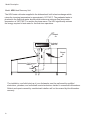
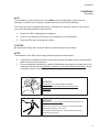
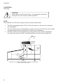
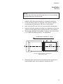
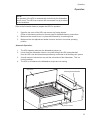
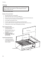
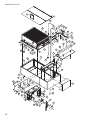
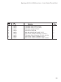
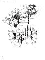
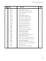
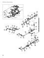
Installation/Operation Guide with Service Replacement Parts
For machines built from 8.21.09 and above
Eseries High Temperature
Heat Recovery Unit
Model:
HRU
3765 Champion Blvd.,
Winston-Salem, NC 27105
336/661-1556 Fax: 336/661-1660
www.championindustries.com
2674 N. Service Road,
Jordan Station Ontario, Canada L0R 1S0
905/562-4195 Fax: 905/562-4618
Issue Date: 2.18.11
Manual P/N 114819 rev.A
Printed in the USA
For future reference, record your dishwasher information in the box below.
Model Number__________________________ Serial Number_______________________
Voltage________________Hertz_____________ Phase__________________
Champion Service Agent __________________________________ Tel:______________________
Champion Parts Distributor _________________________________ Tel:______________________
ATTENTION:
The dishwasher model no., serial no., voltage, Hz and phase are needed to identify
your machine and to answer questions.
Please have this information on-hand
if you call for service assistance.
For all models:
The data plate mounts to one
side of the top-mounted
control cabinet.
National Service Department
In Canada:
Toll-free: 800/ 263-5798
Tel:
905/ 562-4195
Fax:
905/ 562-4618
email: [email protected] In the USA:
Toll-free: 800/ 858-4477
Tel:
336/ 661-1556
Fax: 336/ 661-1660
email: [email protected]
The USGBC and the CaGBC Member Logos are trademarks owned by the U.S. Green Building Council
and The Canadian Green Building Council, respectively, and are used by permission.
The logos signify only that Champion Industries is a
USGBC member and a CaGBC member; USGBC and CaGBC do not review,
certify nor endorse the products or services offered by its members.
COPYRIGHT © 2010 All rights reserved
Printed in the USA
Revision History
Revision History
The revision history contains part number changes and instructions not available at the time
of printing. We reserve the right to make any changes without notice and without incurring
any liability by making these changes.
Equipment owners may request a revised manual at no charge, by calling:
1 (800) 858-4477 in the U.S.A. or by calling 1 (800) 263-5798 in Canada.
Revision
Date
Revised
Pages
Serial Number
Effectivity
Revision
Description
8.6.10
All
Engineered System
Release of First Edition
2.18.11
12-13
J11022850
Added blower junction box
14-21
J11022850
Added 2 amp circuit breaker
31
J10022850
Revised schematic for circuit breaker
i
Limited Warranty
LIMITED WARRANTY
Champion Industries Inc. (herein referred to as Champion), 3765 Champion Blvd., Winston-Salem, North Carolina 27105,
and P.O. Box 301, 2674 N. Service Road, Jordan Station, Canada, L0R 1S0, warrants machines, and parts,
as set out below.
Warranty of Machines: Champion warrants all new machines of its manufacture bearing the name "Champion" and installed within the United States and Canada to be free from defects in material and workman
ship for a period of one (1) year after the date of installation or fifteen (15) months after the date of shipment by
Champion, whichever occurs first. [See below for special provisions relating to glasswashers.] The warranty
registration card must be returned to Champion within ten (10) days after installation. If warranty card is not
returned to Champion within such period, the warranty will expire after one year from the date of shipment.
Champion will not assume any responsibility for extra costs for installation in any area where there are
jurisdictional problems with local trades or unions.
If a defect in workmanship or material is found to exist within the warranty period, Champion, at its election,
will either repair or replace the defective machine or accept return of the machine for full credit; provided;
however, as to glasswashers, Champion's obligation with respect to labor associated with any repairs shall end
(a) 120 days after shipment, or (b) 90 days after installation, whichever occurs first. In the event that Champion elects to repair, the labor and work to be performed in connection with the warranty shall be done during regular working hours by a Champion authorized service technician. Defective parts become the property of Champion. Use of replacement parts not authorized by Champion will relieve Champion of all further liability in connection with its warranty. In no event will Champion's warranty obligation exceed Champion's charge for the machine. The following are not covered by Champion's warranty:
a.
b.
c.
d.
e.
f.
g.
h.
i.
j.
Lighting of gas pilots or burners.
Cleaning of gas lines.
Replacement of fuses or resetting of overload breakers.
Adjustment of thermostats.
Adjustment of clutches.
Opening or closing of utility supply valves or switching of electrical supply current.
Cleaning of valves, strainers, screens, nozzles, or spray pipes.
Performance of regular maintenance and cleaning as outlined in operator’s guide.
Damages resulting from water conditions, accidents, alterations, improper use, abuse, tampering, improper installation, or failure to follow maintenance and operation procedures.
Wear on Pulper cutter blocks, pulse vanes, and auger brush.
Examples of the defects not covered by warranty include, but are not limited to: (1) Damage to the exterior or interior finish as a result of the above, (2) Use with utility service other than that designated on the rating plate, (3) Improper connection to utility service, (4) Inadequate or excessive water pressure, (5) Corrosion from
chemicals dispensed in excess of recommended concentrations, (6) Failure of electrical components due to
connection of chemical dispensing equipment installed by others, (7) Leaks or damage resulting from such
leaks caused by the installer, including those at machine table connections or by connection of chemical
dispensing equipment installed by others, (8) Failure to comply with local building codes, (9) Damage
caused by labor dispute.
Warranty of Parts: Champion warrants all new machine parts produced or authorized by Champion to be free from defects in material and workmanship for a period of 90 days from date of invoice. If any defect in
material and workmanship is found to exist within the warranty period Champion will replace the defective
part without charge.
DISCLAIMER OF WARRANTIES AND LIMITATIONS OF LIABILITY. CHAMPION'S WARRANTY IS ONLY TO THE EXTENT REFLECTED ABOVE. CHAMPION MAKES NO OTHER WARRANTIES, EXPRESS OR IMPLIED, INCLUDING,
BUT NOT LIMITED, TO ANY WARRANTY OF MERCHANTABILITY, OR FITNESS OF PURPOSE. CHAMPION SHALL
NOT BE LIABLE FOR INCIDENTAL OR CONSEQUENTIAL DAMAGES. THE REMEDIES SET OUT ABOVE ARE
THE EXCLUSIVE REMEDIES FOR ANY DEFECTS FOUND TO EXIST IN CHAMPION DISHWASHING MACHINES AND
CHAMPION PARTS, AND ALL OTHER REMEDIES ARE EXCLUDED, INCLUDING ANY LIABILITY FOR INCIDENTALS
OR CONSEQUENTIAL DAMAGES.
Champion does not authorize any other person, including persons who deal in Champion Dishwashing machines
to change this warranty or create any other obligation in connection with Champion Dishwashing Machines.
ii
Table of Contents
Table of Contents
Model HRU: Heat Recovery Unit
Revision History.................................................................................................................... i
Limited Warranty................................................................................................................... ii
Model Description.................................................................................................................. iv
Installation............................................................................................................... 1
Receiving......................................................................... 1
Mounting.......................................................................... 3
Plumbing Connections.................................................... 5
Setting the PRV's............................................................ 6
Operation Lights and Exhaust Blowers........................... 8
Operation ............................................................................................................... 9
Cleaning ............................................................................................................... 10
Service Replacement Parts.................................................................................... 11
One Line Piping Diagram........................................................................................ 29
Operation Logic Diagram ...................................................................................... 33
Electrical Schematic............................................................................................... 34
Model Description
Model: HRU Heat Recovery Unit
The HRU heats cold water supplied to the dishwasher's built-in heat exchanger which
raises the incoming temperature to approximately 110°F/43°C. The preheated water is
plumbed to the final rinse water booster which ensures a minimum final rinse water
temperature of 180°F/82°C to sanitize the clean wares. The HRU significantly reduces
the energy required to heat water for the final rinse operations.
Exhaust
Air
HRU
Pre-heated
Water Out
Exhaust
Air
Cold
Water In
Booster
The installation, and initial start-up of your dishwasher must be performed by qualified
electricians, plumbers, and authorized service technicians trained in commercial dishwashers.
Defects and repairs caused by unauthorized installers will not be covered by the dishwasher
warranty.
iv
Installation
Installation
Receiving
NOTE:
The installation of your Heat Recovery Unit (HRU) must be performed by qualified service
personnel. Problems due to improper installation are not covered by the Warranty.
The HRU may have be installed at the factory. Proceed to the operation section of this manual
if your HRU is already attached to the machine.
1.
Inspect the HRU for damage due to shipping.
2.
Check for any accessories that may have shipped with your dishwasher.
3.
Move the HRU near its permanent location.
CAUTION:
Be careful when lifting and moving the HRU to prevent damage to the machine.
NOTE:
The installation of the HRU must comply with local safety and health codes.
4.
Compare the installation site utility connections with the dishwasher utility connections and
make sure that they are the same.
5.
For new dishwasher installations, install the Dishwasher according to the instructions in the
dishwasher service manual Installation, Operation, and Service Replacement Parts, which
is shipped inside the dishwasher.
WARNING:
Moving Parts may cause INJURY OR DEATH.
USE EXTREME CAUTION WHEN THE CONVEYOR
IS MOVING.
WARNING:
Electrocution or serious injury may result when working on an
energized circuit.
Disconnect power at the main breaker or service disconnect
switch before working on the circuit.
Lock-out and tag the breaker to indicate that work is being
performed on the circuit.
1
Installation
Installation
Receiving
!
CAUTION:
Metal edges in the HRU may be sharp. Use appropriate caution when
working on and in the vicinity of metal components
NOTE:
The installation of the HRU must comply with local safety and health codes.
1.
The HRU weighs approximately 175 lbs./79.4 Kg and mounts on the top of the unload end
of the dishwasher.
2.
The unload exhaust vent of the dishwasher connects to the inlet of the HRU vent and is sealed
with gasket material which has already been installed on the dishwasher.
3.
The HRU is attached to the dishwasher by inserting fasteners from inside the dishwasher
into weldnuts mounted in the HRU. Mounting hardware is included in the installation kit.
Exhaust
Air
HRU
Pre-heated
Water Out
Exhaust
Air
Cold
Water In
Booster
Heat Recovery Unit (HRU) shown installed on a right-to-left dishwasher
without a Blower Dryer Option
2
Installation
Installation
Mounting
NOTE:
The HRU may have been mounted at the factory so the procedures
described below may not be required.
1.
Install the HRU after the dishwasher is completely assembled.
2.
Lift the unit with a forklift or a minimum of four persons capable
of positioning and lowering the HRU into its final position.
3.
Make sure the HRU vent inlet (A) is centered on the dishwasher.
4.
Install the mounting hardware installed in the installation kit from the
inside of the dishwasher hood to secure the HRU to the machine
5.
The mounting hardware (B) includes: (7) Hex hd. bolts 1/4-20 x 5/8",
(7) 1/4" split lock washers, and (7) 1/4" flat washers.
Dishwasher Direction of Travel
A
C
L
B
B
B
B
B
HRU
B
B
Top View of the dishwasher unload section.
(HRU shown in gray)
6.
Electrical power is prewired from the heat recovery control box to
the dishwasher main control cabinet to operate the HRU.
3
Blank Page
This Page
Intentionally
Left Blank
4
Installation
Installation
Plumbing Connections
Refer to the photograph below and follow the instructions to connect the
water lines to the HRU.
1.
Connect compression fittings from the cold water supply line located
at the base of the dishwasher booster heater to the HRU.
2.
Connect compression fittings from the HRU return line at the rear
of the HRU to the booster inlet located at the base of the machine.
3.
Connect the red drain hose from the base of the HRU to the
fitting on the rear drain line of the dishwasher. The fitting is located
directly below the HRU drain line.
COLD WATER
IN
HRU WATER
OUT
HRU DRAIN
OUT
Heat Recovery Unit (HRU) water and drain lines are connected at the rear of the dishwasher.
5
Installation
Installation
Setting the Booster Pressure Reducing Valves (PRV's)
Refer to the illustrations on the next two pages for the location of the water valves and the Green
indicator lights.
1.
Ensure that all utility connections are complete.
2.
Remove the lower front panel of the unload section.
3.
Remove the coil assembly (A) from the multi-rinse valve.
CAUTION:
to prevent damage to the valve coil, energize the multi-rinse valve for as short a
period as needed to make necessary PRV adjustments.
Immediately reinstall the coil assembly when PRV adjustments have been completed.
4.
Turn on main water supplies to the dishwasher. Make sure steam supply is OFF.
5.
Close all of the drain valves.
6.
Remove the main control cabinet cover and set the Auto/Manual switch to the Manual position.
7.
Turn ON main breaker power to dishwasher.
8.
Turn OFF main breaker power to the booster and optional blower dryer (if equipped).
9.
Turn dishwasher main power switch ON.
10. Allow dishwasher tanks to completely fill with water.
11. When dishwasher tanks are full, turn dishwasher main power switch OFF.
12. Turn the Auxiliary wash tank drain handle open and drain the tank (leave the drain open).
(This places the dishwasher in a FILL mode because the tank is empty.)
13. Turn the dishwasher main power switch ON.
14. The Green FILL light in the control cabinet will be ON when the machine is filling.
15. While the machine is filling, adjust the HOT PRV #1 until the final rinse pressure gauge indicates
20 PSI. Tighten the PRV adjustment lock-nut to hold the setting.
16. Close the drain and allow the dishwasher to fill with water.
17. Turn the dishwasher main power switch OFF.
18. Make sure the main breaker or steam supply to the booster is OFF.
Turn the hot water off.
19. Turn the dishwasher control panel Power Switch on.
20. Press the ENERGY SAVER mode selector switch on the main control cabinet.
The green LED will illuminate and the conveyor will run.
21. While the machine is running, adjust the COLD PRV #2 until the final rinse pressure gauge indicates 20
PSI. Tighten the PRV adjustment lock-nut to hold the setting.
22. Now set the cold water PRV #2 by adjusting the PRV until the final rinse pressure gauge indicates 20 PSI
flow pressure. Note that the pressure gauge will cycle on for 15 seconds and then off for 30; therefore, the
pressure gauge will read a flowing pressure for 15 secs., then read the no pressure for 30 seconds.
23. The Green FINAL light will be ON when the Cold water valve is ON. The Green REHEAT light will be ON
when the Hot water valve is ON.
24. To complete the settings: Turn the dishwasher main power switch OFF.
25. Turn the main breaker or steam supply to the booster on.
26. Turn the Automatic/Manual switch inside the control cabinet to the Automatic position.
6
Installation
Installation
Setting the Booster Pressure Regulating Valves (PRV's)
1.
Reinstall the main control cabinet cover.
2.
Reinstall the coil assembly on the multi-rinse valve (A).
3.
Open all drain valves and drain the dishwasher.
4.
Turn the hot water supply ON.
5.
Makes sure the main power supply is ON.
Multi-rinse Valve
A
To Final Rinse
Hot PRV #1
To HRU
To Tank
Fill
Hot Water In
Cold PRV #2
From HRU
Cold Water In
Electric HRU Booster PRV Locations
(Right-to-left dishwasher installation).
Multi-Rinse Valve
A
Cold
PRV #2
Hot In
Hot
PRV #1
Cold In
Steam In
Steam HRU Booster PRV Locations
(Right-to-left dishwasher installation).
7
Installation
Operation Indicator Lights
Green Indicator Lights
Green indicator lights inside the HRU control cabinet
indicate the operation state of the valves during the
set-up procedures. Refer to the set-up procedures on the
previous two pages to set the pressure reducing valves.
REHEAT
FINAL
In addition, the green lights will indicate the operation of the
booster valves during normal operation. Refer to
the simplified logic diagram below which shows the
interaction of the timers, thermistor reader (temperature
control module) and the booster solenoid valves.
FILL
30 Sec.Timer
15 Sec.Timer
Exhaust Blowers
The HRU Exhaust Blowers operate when the dishwasher
is running.
Exhaust Blower 1: runs whenever the dishwasher pumps
and the final rinse are running.
Exhaust Blower 2: runs when only the final rinse is running.
Exhaust Blower
Fan 2 (Wire 17B)
Exhaust Blower
Fan 1 (Wire 11B)
Thermistor
Reader
Indicator lights inside the control cabinet
indicate the operation of the valves.
Exhaust Blowers as viewed from the front of the dishwasher.
(Left-to-Right Dishwasher Operation Shown)
NOTE:
A detailed Logic Diagram is included at the
end of this manual
The 15 second timer runs, then the 30 second timer runs in a alternating time cycle
Booster Temperature Thermistor Input
15 Second Timer (T1)
Controls the operation of the T1R
relay. The T1R relay powers the
COLD water valve depending
on the temperature input to
the Thermistor Reader.
15 Seconds
Elapsed
Thermistor Reader (TS)
The thermistor reader constantly
monitors the temperature of the
booster tank. It controls the
power to the timers through the
contacts of the T1R and T2R
relays. The operation of the
valves is dependent on the
temperature inputs to TS.
Temperature
Less than
110˚F
30 Second Timer (T2)
Controls the operation of the T2R
relay. The T2R relay powers the
HOT water valve depending
on the temperature input to
the Thermistor Reader.
Temperature
Greater than
110˚F
Simplified HRU Cold and Hot Water Switching Logic Diagram
8
Hot Water/Reheat Valve
Cold Water/Final Rinse Valve
Operation
Operation
NOTE:
The operation of the HRU is automatically controlled by the dishwasher
control circuit. The HRU has a control that is accessed only by a trained
service technician.
Refer to the illustration below to prepare the HRU for operation.
1.
Open the top cover of the HRU and remove any foreign objects.
(Refer to the cleaning section on the next page for detailed cleaning instructions.
2.
Make sure the access cover is in place and secured by its retaining studs.
3.
Make sure the vent adjustment handle is secure and set to its normal operating
position.
Automatic Operation:
1.
The HRU operates whenever the dishwasher pumps run.
2.
Hot air from the dishwasher interior is recycled through the HRU and exhausted
from the HRU vent which has been permanently connected to the building vent system.
3.
A small amount of exhaust air may exit the unload end of the dishwasher. This is a
normal condition.
4.
The HRU is off whenever the dishwasher pumps are not running.
Top Cover
Vent Adjustment Handle
Access Cover
9
Cleaning
Cleaning
CAUTION:
Do not place objects on top of the condenser coil nor with the cleaning
devices. Avoid the use of cleansers or other detergents to prevent
damage to the top of the coil
Refer to the illustration below.
Monthly Cleaning Schedule:
1.
Open the top cover over of the HRU.
2.
Remove the front cover of the unit by sliding it up.
3.
Remove the front access cover which is retained by three knurled thumbscrews.
4.
Flush the top of the condenser coil with fresh water.
5.
Do not wipe nor brush the coil fins.
6.
Flush the underside below the condenser coil with fresh water.
7.
Leave the HRU covers off overnight to allow the inside of the unit to air dry.
8.
Reassemble in reverse order at the beginning of the day.
Daily Cleaning Schedule:
1. Inspect the interior unit for
accumulated debris.
2.
Wipe the exterior of the unit
with a soft cloth and mild
detergent.
3.
DO NOT HOSE THE
EXTERIOR OF THE UNIT
WITH WATER.
Annual Cleaning Schedule:
1. Contact an authorized
service agent to perform
general maintenance and
major cleaning.
Front Cover
Top Cover
Condenser Coil
Access Cover
10
Service Replacement Parts
Service Replacement Parts
IllustrationsPage
Heat Recovery Unit..............................................................................................................12
Control Cabinet - Prior to S/N J11022850............................................................................14
Control Cabinet Terminal Block - Prior to S/N J11022850....................................................16
Control Cabinet - Beginning with S/N J11022850 and above...............................................18
Control Cabinet Terminal Block - Beginning with S/N J11022850 and above......................20
HRU Electric Booster Assembly...........................................................................................22
HRU Electric Booster Piping................................................................................................24
HRU Steam Booster Assembly............................................................................................26
HRU Steam Booster Piping .................................................................................................28
11
Heat Recovery Unit
34
1
55
16
52
45
32
33
21
3
18
15
35
20
5
40
41
43
44
2
42
16 38
17
56
37
1
22
21
22
13 24
23
46
19
4
6
36
26
12
30
11
10
51
53
14
31
49
9
6
54
26
50
48
7
28
27
59
29
58
28
60
27
64
37
27
47
57 25
26
8
35
39
64
61
65
26 62 66
63
12
Heat Recovery Unit
1
2
3
4
5
6
7
8
9
10
11
12
13
14
15
16
17
18
19
20
21
22
23
24
25
26
27
28
29
30
31
32
33
34
35
36
37
38
39
40
41
42
43
44
45
46
47
48
49
50
51
52
53
54
55
56
57
58
59
60
61
62
63
64
65
66
100097
0512027
100156
333557
100209
100735
100736
100738
101187-1
101187-2
101187-3
101187-4
101187-5
101187-6
101259
101502
102415
102504
102505
102514
102519
103418
104883
104971
106026
106482
107033
107136
107966
107967
109910
109924
109925
111561
113269
333556
114121
114335
114633
114646
114647
114648
114649
114650
114710
305141
333143, (333216)
333144, (333217)
333145
333151, (333220)
333152, (333221)
333153, (333222)
333341, (333342)
333345, (333346)
333350, (333351)
333353
333355, (333357)
333358
333359
333360
100141
100734
114365
114879
114880
334221
SCREW, TRUSS HD., 10-32 X 1/2" SST
COUPLER, BARB 3/4" MPT X 3/4" HOSE
LOCKNUT, 3/4" NPT BRASS
ACCESS PLATE WELDMENT, HRU PLENUM G3
NIPPLE, 1/2" NPT X CLOSE BRASS
BOLT, HEX HD., 1/4-20 X 5/8" SST
BOLT, HEX HD., 1/4-20 X 3/4" SST
BOLT, HEX HD., 1/4-20 X 1" SST
HANDLE, THREADED DAMPER ASSY.
HANDLE, DAMPER ASSY.
WING NUT, DAMPER REGULATOR ASSY.
WASHER, DAMPER REGULATOR ASSY.
BRACKET ASSY., LOCK PIN DAMPER REGULATOR
BEVELLED WASHER, DAMPER ASSY.
PLUG, 1/8" NPT SQ. HD., BRASS
NIPPLE, RTOE 3/4" NPT X 4-1/2" LG. BRASS
COUPLING, 3/4" NPT BRASS
PLUG, 1/2" NPT SQ. HD., BRASS
PLUG, 3/4" NPT SQ. HD., BRASS
TEE, 1/2" NPT BRASS
TEE RED., 1/2" X 1/2" X 3/4" BRASS
BUSHING, REDUCING, 1/2" NPT X 1/8" NPT BRASS
SCREW, ROUND HD., 6-32 X 3/8" SST
HEX GRIP NUT, 6-32" SST
WASHER, FLAT SST
WASHER, LOCK 1/4" SPLIT SST
WASHER, FLAT SST
SCREW, HEX HD., 10-32 X 3/8" SST
HEX GRIP NUT, 10-32 W/NYLON INSERT
HEX GRIP NUT, 1/4-20 W/NYLON INSERT
FITTING, COMP 5/8" OD X 90° BRASS
FITTING, COMP 5/8" OD UNION BRASS
FITTING, COMP 5/8" OD X 1/2"MPT BRASS
HANDLE, ACCESS DOOR, FLUSH MOUNT
CLAMP, HOSE M12 11/16"-1-1/4" W/CS SCREW
CLIP, ACCESS PLATE PIVOT, HRU PLENUM
HOSE, 3/4" SYNTHETIC RUBBER
THERMISTOR, 10KΩ, 36" LEAD
BLOWER, HEAT RECOVERY UNIT
RECEPTACLE, 1/4 TURN
SPRING, 1/4 TURN SST
WASHER, WEAR, CLIPPED
RING, RETAINER SST
STUD, 1/4 TURN, KNURLED SST
COIL, BATTERY, HEAT RECOVERY UNIT GEN.3
BLADE, DAMPER, VENT STACK
PANEL, FRONT FAN END, RL
(LR NOT SHOWN)
PANEL, FRONT COIL END, RL
(LR NOT SHOWN)
ANGLE, FRONT PANEL STOP
PANEL, REAR, FAN END, RL
(LR NOT SHOWN)
PANEL DEVP., REAR COIL END, RL (LR NOT SHOWN)
PANEL DEVP., REAR, CENTER, RL (LR NOT SHOWN)
BODY WELDMENT, HRU, RL
(LR NOT SHOWN)
DUCT WELDMENT, OUTLET, RL
(LR NOT SHOWN)
COIL COVER WELDMENT,RL
(LR NOT SHOWN)
PANEL WELDMENT, TOP VENT
PLATE WELDMENT, BLOWER MTG, RL (LR NOT SHOWN)
PLATE DIVIDER, RH COIL CHAMBER
PLATE WELDMENT, DIVIDER LH
ANGLE DIVIDER MOUNTING
HEX, GRIP NUT, 1/4-20 SST CTRL LOCK
BOLT, HEX HD. 1/4-20 X 1/2" SST
CONNECTOR, STRAIN RELIEF, CORD
BOX, WEATHERPROOF, 4-HOLE
COVER ASSY., WEATHERPROOF W/GASKET
BRACKET, FAN JUNCTION BOX HRU
20
4
2
2
1
12
7
8
1
1
1
1
1
1
1
2
2
1
2
1
2
2
4
4
15
27
12
9
3
14
2
2
2
1
6
4
A/R
1
2
2
2
2
2
2
1
1
1
1
1
1
1
1
1
1
1
1
1
1
1
4
2
4
2
1
1
1
13
Control Cabinet - Prior to S/N J11022850
4
3
2
1
7
See next page
6
8
12
5
10
9
11
21
13
7
20
20
15
16
17
18
19
21
7
14
Prior to S/N J11022850
(Left to Right Direction Shown)
14
22
20
Prior to S/N J11022850 - Control Cabinet
1
2
3
4
5
6
7
8
9
10
11
12
13
14
15
16
17
18
--19
20
21
22
333305
106364
107966
333536
114661
113769
100095
114666
111068
111036
114662
100007
106396
333306
114655
111823
106402
107091
111521
100003
106482
100735
333307
CONTROL CABINET WELDMENT, HRU W/XFRM
LIGHT, INDICATOR
HEX GRIP NUT, 10-32 W/NYLON INSERT SST
BRACKET, LIGHTS HRU CONTROL CABINET
TIMER, FIXED 15 SECOND 120VAC
DIN RAIL 35MM X 15MM
SCREW, ROUND HD., 10-32 X 3/8" SST
RESISTOR, 10Ω 2W
RELAY, 2-POLE 10A, 120VAC
SOCKET, RELAY 2 POLE
TIMER, FIXED 30 SECOND 120VAC
SCREW, TRUSS HD., 10-32 X 3/8" SST
SCREW, TRUSS HD., 10-32 X 1-1/4" SST
COVER, CONTROL CABINET HRU W/XFRM
TEMPERATURE CONTROL MODULE, HRU
FUSE, ATDR 6A
BLOCK, FUSE 2 POLE
TRANSFORMER, 500VA 240/480, 230/460:120
TRANSFORMER, 250VA 575:120VAC
HEX PLAIN NUT, 1/4-20 SST
WASHER, LOCK, 1/4" SPLIT SST
BOLT, HEX HD., 1/4-20 X 5/8" SST
INNER PANEL, CONTROL CABINET HRU W/XFMR
1
3
2
1
1
A/R
9
2
6
6
1
4
2
1
1
2
1
1
1
4
12
8
1
15
Control Cabinet Terminal Block - Prior to S/N J11022850
3
4
2
2
1
5
6
7
8
16
4
9
Prior to S/N J11022850 - Control Cabinet Terminal Block
1
2
3
4
5
6
7
8
9
114520
114512
114517
114519
114522
114518
114515
114516
114521
TERMINAL, SINGLE MZB 1.5-NS35
TERMINAL, SINGLE, ST 2.5 (GRAY)
TERMINAL, DOUBLE STTB 2.5
END BLOCK, E/NS 35N
BUS BAR 4-POLE (CUT TO FIT)
END COVER, DOUBLE TERMINAL, D-STTB 2.5
TERMINAL, SINGLE GROUND, ST 2.5 PE (GREEN)
END COVER, SINGLE TERMINAL D-ST 2.5
END COVER, SINGLE TERMINAL D-MZB 1.5 NS35
2
9
4
2
1
1
1
1
1
17
Control Cabinet - Beginning with S/N J11022850 and above
FILL
REHEAT
RINSE
See next page for
terminal block detail.
17
16
19
18
20
9
14
8
4
3
15
6
13
1
12
2
11
10
5
7
Prior to S/N J11022850
(Right to Left Direction Shown)
(For left to right direction, flip inner panel to place transformer to the left)
18
Beginning with S/N J11022850 and above - Control Cabinet
1
2
3
4
5
6
7
--8
9
10
11
12
13
14
15
16
17
18
19
20
100003
100095
100735
106396
106402
106482
107091
111521
111036
111068
111823
333307
114655
114662
114661
114666
114862
107966
333536
106364
113769
HEX PLAIN NUT, 1/4-20 SST
SCREW, ROUND HD., 10-32 X 3/8" SST
BOLT, HEX HD., 1/4-20 X 5/8" SST
SCREW, TRUSS HD., 10-32 X 3/8" SST
BLOCK, FUSE 2 POLE
WASHER, LOCK, 1/4" SPLIT SST
TRANSFORMER, 500VA 240/480, 230/460:120
TRANSFORMER, 250VA 575:120VAC
SOCKET, RELAY 2 POLE
RELAY, 2-POLE 10A, 120VAC
FUSE, ATDR 6A
INNER PANEL, CONTROL CABINET HRU W/XFMR
TEMPERATURE CONTROL MODULE, HRU
TIMER, FIXED 30 SECOND 120VAC
TIMER, FIXED 15 SECOND 120VAC
RESISTOR, 10Ω 2W
CIRCUIT BREAKER, 2A
HEX GRIP NUT, 10-32 W/NYLON INSERT SST
BRACKET, LIGHTS HRU CONTROL CABINET
LIGHT, INDICATOR
DIN RAIL 35MM X 15MM X 13" LG.
4
9
8
2
1
12
1
1
6
6
2
1
1
1
1
2
2
2
1
3
A/R
NS
NS
333306
333305
COVER, CONTROL CABINET HRU W/XFRM
CONTROL CABINET WELDMENT, HRU W/XFRM
1
1
19
Control Cabinet Terminal Block - Beginning with S/N J11022850 and above
3
6
2
7
4
1
4
8
9
5
5
20
Beginning with S/N J11022850 and above - Control Cabinet Terminal Block
1
2
3
4
5
6
7
8
9
114520
114512
114517
114519
114522
114518
114515
114516
114521
TERMINAL, SINGLE MZB 1.5-NS35
TERMINAL, SINGLE, ST 2.5 (GRAY)
TERMINAL, DOUBLE STTB 2.5
END BLOCK, E/NS 35N
BUS BAR 10-POLE (CUT POLES TO FIT)
END COVER, DOUBLE TERMINAL, D-STTB 2.5
TERMINAL, SINGLE GROUND, ST 2.5 PE (GREEN)
END COVER, SINGLE TERMINAL D-ST 2.5
END COVER, SINGLE TERMINAL D-MZB 1.5 NS35
2
7
5
2
2
1
1
1
1
21
HRU Electric Booster Assembly
26
To Final Rinse
Hot PRV
11
27
To Tank
Fill
Hot Water In
19
To HRU
14
1
Cold PRV
From HRU
16
Cold Water In
15
4
Control
Thermostat
High Limit Thermostat
24
7
8
13
6
2
20
25
17
18
22
23
12
9
21
10
3
22
5
HRU Electric Booster Assembly
1
100003
HEX PLAIN NUT 1/4-20 SST
11
2
100097
SCREW, TRUSS HD. 10-32 X 1/2” SST
2
3
100100
SCREW, ROUND HD., 8-32 X 1/4” SST
2
4
100113
CAP, 3/4” NPT SST
1
5
100154
HEX PLAIN NUT, 5/16-18 SST
6
6
100734
BOLT, HEX HD., 1/4-20 X 1/2” SST
2
7
100736
BOLT, HEX HD., 1/4-20 X 3/4” SST
2
8
100739
BOLT, HEX HD., 5/16-18 X 3/4” SST
2
9
100740
BOLT, HEX HD., 5/16-18 X 1” SST
4
10
102376
WASHER, FLAT 5/16-18 SST
4
11
102505
PLUG, 3/4” NPT SQ. HD., BRASS
1
12
106013
WASHER, LOCK SPLIT 5/16” SST
6
13
106026
WASHER, FLAT 1/4” SST
2
14
106482
WASHER, LOCK SPLIT 1/4” SST
2
15
107967
HEX GRIP NUT, 1/4-20 SST W/NYLON
14
16
108576
COVER, BOOSTER HEATER
1
17
109069
THERMOSTAT, CONTROL
1
18
109682
COVER, THERMOSTAT BOX
1
19
109985
O-RING, BOOSTER HEATER ELEMENT
3
20
110561
THERMOSTAT, HIGH LIMIT
1
21
206668
ANGLE, ELECTRIC BOOSTER SUPPORT
1
22
206919
ANGLE, ELECTRIC BOOSTER SUPPORT, D3
1
23
314102
BOX, DUAL THERMOSTAT
1
24
328254
BRACKET, BOOSTER SUPPORT W/HOLE
1
25
330571
BRACKET, PIPING SUPPORT ELEC. BOOSTER
1
26
414331
TANK, BOOSTER
1
27
111232
ELEMENT, BOOSTER 10KW, 208/60/3
3
23
HRU Electric Booster Piping
A
Hot PRV
To Final Rinse
B
To HRU
To Tank
Fill
Hot Water In
C
3
Cold PRV
10
D
4
8
From HRU
2
B
Cold Water In
2
18
1
2
12
3
7
3
2
2
2
17
10
13
10
9
A
6
5
5
11
C
2
3
4
4
19
9
9
6
3
1
5
14
2
3
5
2
2
15
2
D
4
3
2
3
24
16
9
4
8
10
HRU Electric Booster Piping
1
100184
NIPPLE, 3/4” NPT X CLOSE, BRASS
2
2
100209
NIPPLE, 1/2” NPT X CLOSE, BRASS
12
3
102438
ELBOW, STREET, 1/2” NPT X 90°, BRASS
8
4
102514
TEE, 1/2” NPT BRASS
5
5
102549
UNION, 1/2” NPT, BRASS
4
6
102392
BUSHING, REDUCING 3/4” NPT X 1/2” NPT, BRASS
2
7
109879
FITTING, COMP. 7/8” OD X 3/4” MPT, BRASS
1
8
108265
VALV, PRESSURE REGULATING, 1/2” NPT BRONZE
2
9
109925
FITTING, COMP., 5/8” OD X 1/2” MPT BRASS
4
10
111352
VALVE, SOLENOID 1/2” NPT 115V BRASS
4
---
109902
KIT, REPAIR, 1/2” SOLENOID VALVE
A/R
---
108516
COIL, SOLENOID VALVE 1/2” NPT 115V
A/R
11
102444
ELBOW STREET, 1/2” NPT 90°, BRASS
1
12
102492
NIPPLE, 1/2” NPT X 2” LG. BRASS
1
13
102570
NIPPLE, 1/2” NPT X 4” LG. BRASS
1
14
100206
NIPPLE, 1/2” NPT X 2-1/1” LG. BRASS
1
15
102504
PLUG, 1/2” NPT, SQ. HD. BRASS
1
16
104421
STRAINER, LINE, 1/2” NPT BRONZE
1
17
110768
STRAINER, LINE, 3/4” NPT BRONZE
1
18
102525
TEE, RED, 3/4” X 1/2” X 1/2” NPT BRONZE
1
19
102574
NIPPLE, 1/2” NPT X 5” LG. BRASS
1
25
HRU Steam Booster Assembly
9
12
4
2
5
11
2
6
1
8
10
6
5
7
1
3
26
8
HRU Steam Booster Assembly
1
100140
HEX PLAIN NUT, 3/8-16 SST
6
2
100153
BOLT, HEX HD. 3/8-16 X 1" SST
4
3
100154
HEX PLAIN NUT, 5/16-18 SST
2
4
100739
BOLT, HEX HD., 5/16-18 X 3/4" SST
2
5
102376
WASHER, FLAT 5/16" SST
4
6
104618
WASHER, FLAT 3/8" SST
4
7
106013
WASHER, LOCK 5/16" SPLIT SST
2
8
106407
WASHER, LOCK 3/8" SPLIT SST
6
9
112334
U-BOLT, #180 BOOSTER
1
10
330244
BASE, DECK STEAM BOOSTER
1
11
330245
SUPPORT, STRAINER STEAM BOOSTER
1
12
601923
BOOSTER SUB ASSY, STEAM #120 RL
1
27
HRU Steam Booster Piping
28
HRU Steam Booster Piping
1
100123
PETCOCK, 1/4” FEMALE BRASS
1
2
100134
ELBOW, STREET, 1” NPT X 90° MI
2
3
100979
BUSHING, RED 1-1/2” NPT X 1” NPT BI
2
4
102288
ELBOW, 1/2” NPT X 90° MI
1
5
102402
BUSHING, RED. 3/4” NPT X 1/2” NPT BI
1
6
103465
BUSHING, RED. 3/4” NPT X 1/2” NPT BI
1
7
103586
UNION, 1/2” NPT MI
1
8
105733
ELBOW, 1” NPT, X 90° MI
1
9
105778
UNION 1/2” NPT MI
1
10
105780
UNION 1” NPT MI
2
11
105782
NIPPLE 1/2” NPT X CLOSE BI
2
12
105786
NIPPLE 1/2” NPT X 3” NPT LG. BI
1
13
105847
NIPPLE, 1” NPT X CLOSE BI
1
14
105850
NIPPLE, 1” NPT X 2“ LG. BI
3
15
105851
NIPPLE, 1” NPT X 2-1/2” LG. BI
1
16
105881
NIPPLE, 1-1/2” NPT X CLOSE BI
2
17
106051
STRAINER, LINE 2” NPT BI
1
18
106607
NIPPLE, 2” NPT X CLOSE BI
1
19
107004
TEE, RED 1-1/2” X 1/2” X 1-1/2” MI
1
20
107657
TEE, RED, 2” X 1-1/2” X 1-1/2” NPT MI
1
21
110005
VALVE, 1” NPT STEAM
1
22
111380
STEAM TRAP, 1/2” NPT TDC
1
23
112349
BUSHING, RED. 1-1/2” NPT X 1/2” NPT BI
1
24
112359
TEE, RED. 3/4” X 3/4” X 1” NPT BI
1
25
112748
NIPPLE, 1/2” NPT X 3-3/4” LG. BI
1
26
114167
BOOSTER, THRUSH #120-1
1
27
601921
PIPING ASSY, STEAM BOOSTER, EXIT RL
1
28
601922
PIPING ASSY, STEAM BOOSTER, INLET RL
1
29
113352
VALVE, 1/2” NPT SOLENOID 12OVAC
4
30
110768
STRAINER, LINE 3/4” NPT BRONZE
1
31
107550
VALVE, PRV 3/4” NPT BRONZE
1
32
110005
VALVE, STEAM 1” NPT SOLENOID 120VAC
1
33
109069
THERMOSTAT, CONTROL W/ CAPILLARY
1
29
Blank Page
This Page
Intentionally
Left Blank
30
Electrical Schematics and Operation Logic Diagram
One Line Piping Diagram
Operation Logic Diagram
and
Electrical Schematic
31
Blank Page
This Page
Intentionally
Left Blank
32
One Line Piping Diagram
FROM MAIN CABINET
MULTIRINSE
HEADER
MULTI-RINSE VALVE
USED ON EEUC ONLY
FAN 1
COLD WATER VALVE
COLD WATER
FAN 2
FINAL
RINSE
HEADER
COIL TEMP
BSTR
COIL
V1
INITIAL FILL VALVE
V2
REHEAT RINSE VALVE
V3
HOT WATER
ONE LINE DIAGRAM FOR HEAT RECOVERY UNIT (HRU)
MODELS - EUCC4, EUCC8, EUCC6, EEUCC8, EEUCC6, EEUCC4
33
Operation Logic Diagram
HRU Logic Diagram
34
v.8410
Electrical Schematic
35
Blank Page
This Page
Intentionally
Left Blank
36