1
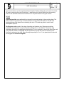
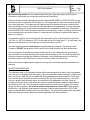
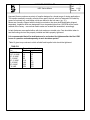
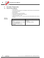
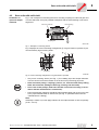
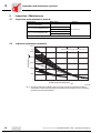
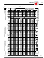
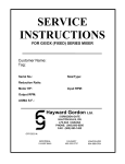
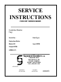
SERVICE
INSTRUCTIONS
FOR HRF SERIES MIXER
Customer Name:
Tag:
Serial No.:
Size/Type:
Reduction Ratio:
Motor HP:
Input RPM:
Output RPM:
AGMA S.F.:
Hayward Gordon Ltd.
5 BRIGDEN GATE
HALTON HILLS, ON
L7G 0A3 CANADA
PHONE: (905) 693-8595
FAX: (905) 693-1452
OFFICES IN:
MONTREAL
514-697-6445
CALGARY
403-253-2737
VANCOUVER
604-986-8764
HAYWARD GORDON LTD
HRF Series Mixers
Page
1
Rev:
1
Date 11/99
Section: RF
TABLE OF CONTENTS
Initial inspection ...................................................................................................... 3
Storage
General ........................................................................................................ 3
Motors and Gear Drives............................................................................... 3
Seals ........................................................................................................... 4
Shafts and Impellers .................................................................................... 4
Installation and Operation
General ........................................................................................................ 4
Mixer Assembly............................................................................................ 5
Mounting ...................................................................................................... 5
Motors .......................................................................................................... 6
Gear Drives .................................................................................................. 6
Seals ........................................................................................................... 6,7
Shafts and Impellers .................................................................................... 7,8
Lubrication
Bearings ....................................................................................................... 9
Motors and Gear Drives............................................................................... 9
Seals ........................................................................................................... 9
Maintenance
Motors .......................................................................................................... 10
Gear Drives .................................................................................................. 10
Trouble Shooting..................................................................................................... 11,12
APPENDIX ........................................................................................................... 13
Parts Lists .................................................................................................... 14
Impeller Blade Bolt and Set Screw Torque.................................................. 15
Stuffing Box Instructions .............................................................................. 16
Stuffing Box, High Pressure......................................................................... 17
Single Mechanical Seal................................................................................ 18
Double Mechanical Seal .............................................................................. 19
Commissioning and Service
Copyright 2002 © Hayward Gordon Limited
Specifications subject to change without prior notice
HAYWARD GORDON LTD
HRF Series Mixers
Page
1
Rev:
1
Date 11/99
Section: RF
HRF MODEL NUMBERING
HRF mixers have model numbers of the format;
HRFX -_ _ -_ _ _
The digits in underscore indicate numeric placeholders and provide specific
information to Hayward Gordon.
Depending on the features of your HRF mixer there may be the letter "S" or the
letter "M" following HRF in the model number.
HRFX models include baseplate with lip seal.
HRFS models include mounting flange with stuffing box.
HRFM models include mounting flange with mechanical seal.
Please provide complete Mixer Model Number and Mixer Serial Number when
information or service is required. This information should be copied from the
mixer nameplate to the front cover of this Service Manual.
HAYWARD GORDON LTD
HRF Series Mixers
Page
2
Rev:
1
Date 11/99
Section: RF
INITIAL INSPECTION
Care should be exercised in uncrating and handling. Miscellaneous parts (turbine hubs, turbine
blades, fasteners, coupling hubs, etc.) may be boxed separately and attached to the crate or may
be wired or bolted to the crate. DO NOT DISCARD CRATE without carefully making sure that all
mixer parts have been removed. The unit should be inspected carefully and any shipping damage
reported to Hayward Gordon Limited. A claim should be filed immediately with the carrier involved.
Damage resulting from improper handling can affect the operation and life of your Hayward
Gordon mixer. Particular care should be taken to prevent bending the shaft, which has been
straightened within a few thousandths of an inch.
Never lift or support the unit by the end of the shaft.
STORAGE
GENERAL
For storage of the mixer, do not remove the protective coating. Add additional protective coating
as may be required for condition and period of storage.
MOTORS and GEAR DRIVES
Hayward Gordon strongly recommends that mixer gear drives be kept in a dry, temperature
controlled indoor storage area. Mixer drives must be sealed from the atmosphere during storage,
make sure breathers are replaced by plugs. Store mixers such that the gear drives are in their
normal vertical configuration and fill the gear case completely with the proper grade of oil. Rotate
input or output shaft several revolutions each month. If these conditions are carefully maintained,
storage durations of up to two years are possible.
If an indoor area is not available with temperature and humidity control, the next best option is
indoors without these controls. In this case, wrap the motor in plastic with desiccant bags inside
and replace the desiccant bags monthly.
Outdoor storage is not recommended. If outdoor storage is unavoidable, keep all of the mixer
components off the ground on skids or platforms and cover the equipment with a waterproof
covering. Wrap the motor in plastic with desiccant bags inside and replace the desiccant bags
monthly.
SEALS
Double mechanical seal housings and mechanical seal lubricators are shipped from the factory
coated internally with a rust preventative which is compatible with most sealing fluids. The
components as shipped are adequately protected for short-term storage in heated indoor
environment. Outdoor storage of mechanical seal units is not recommended; however, when
HAYWARD GORDON LTD
HRF Series Mixers
Page
5
Rev:
1
Date 11/99
Section: RF
unavoidable the seal housing and lubricator pot should be completely filled with a lubricant
compatible with the sealing fluid to be used in service.
SHAFTS and IMPELLERS
The shaft shipped with your unit was straightened at the factory to within a few thousandths of an
inch. Care should be taken in the storage of the shaft to see that it is fully supported along its
entire length and to see that heavy items are not placed on unsupported sections of the shaft. For
outdoor storage of carbon steel shafts and impellers, a suitable grease or rust preventative should
be applied to the parts.
INSTALLATION AND OPERATION
GENERAL
Proper installation and operation is the key to long trouble free mixer service. The following is a list
of points to cover during installation and operation:
1.
2.
3.
4.
5.
6.
7.
8.
Ensure the mixer rotation is correct before permanently wiring the motor.
Read all tags, nameplates and this manual prior to operating the unit.
Check motor operating amperage against motor nameplate amperage.
Do not operate in a fluid with a specific gravity or viscosity higher than that for which the unit is
designed.
Do not attempt to start a unit with the impeller buried in solids or in a "set up" fluid.
Maintain operating temperatures and pressures of vessel within design limitations for stuffing
box and mechanical seal units.
A minimum of 4" radial clearance must be maintained between the impeller and any
obstruction.
Any anticipated changes in motor horsepower, mixer speed, shaft length, impeller diameter or
blade width, etc. should be discussed with Hayward Gordon prior to making changes.
MIXER ASSEMBLY
All units are completely assembled except for the following items:
1. The extension shaft must be inserted through the lower bearing replacing the snap ring on the
shaft and coupling the shaft with the sleeve coupling. All setscrews are then to be tightened,
refer to page 14 for diagram.
2. Impellers turning at speeds higher than 100 RPM are statically balanced and are to be
assembled according to the match marks. Values shown in Table III (pg. 8) indicate torquing
requirements.
3. Mixers supplied with in-tank couplings are to be assembled using the hardware supplied and
torqued to values shown in Table III (pg. 8).
HAYWARD GORDON LTD
HRF Series Mixers
Page
2
Rev:
1
Date 11/99
Section: RF
Open tank models are mounted separately from the tank on a steel structure. These units
include an integral lip seal and bearing cartridge in the base plate.
Stuffing box models mount with a standard ANSI flange to a nozzle or pad directly on the vessel.
Mechanical seal models mount with a standard ANSI flange to a nozzle or pad directly on the
vessel. EXTREME CARE SHOULD BE TAKEN IN HANDLING AND IN INSTALLING TO
ENSURE THAT THE SHAFT IS NOT JARRED, CAUSING DAMAGE TO THE DELICATE
MECHANICAL SEAL PARTS.
MOUNTING
Mixers are mounted in the vertical position only and care should be taken to level the support
structure or nozzle.
The mixer itself has been designed to accept the bending moments and torque reactions
produced by the impeller(s) operating in the fluid. These loads will be transmitted to the support
and therefore the mounting system must be strong enough to support all the loads produced by
the mixer. The support structure must also be rigid enough to prevent dynamic deflections greater
than 0.25° in any direction. Size the support structure to accommodate the bending moment,
torque reaction and static weight shown on the general arrangement drawing.
MOTORS
Ample circulation of air during operation is very important in obtaining full performance and long
life from an electric motor. Minimize obstructions to free circulation in areas where motors are
installed. Avoid choking off the suction inlets on fan cooled motors. The life of the motor will be
decreased if its temperature during operation exceeds its nameplate ambient rating.
Overload protection should always be provided to avoid motor damage during temporary
overloads, jams or other mishaps.
Prior to permanently wiring the electric motor, check the output shaft rotation with the rotation
indicated on the drive nameplate. DO NOT OPERATE UNIT WITHOUT CHECKING ROTATION.
For standard 3 phase motors the rotation may be reversed by changing any two leads. For
complete details, refer to the attached manufacturer's manual.
GEAR DRIVES
The gear drive has been shipped from the factory filled with the proper grade and quantity of oil.
The reducer is provided with a red painted level plug, a drain plug located at its lowest spot and a
blue painted plug indicating the location for the breather. The breather is shipped in a plastic bag
attached to the gearbox. In the case of gear motors the breather plug is shipped inside the motor
terminal box. When the installation of the drive is completed, the blue plug, located at the highest
HAYWARD GORDON LTD
HRF Series Mixers
Page
2
Rev:
1
Date 11/99
Section: RF
spot on the reducer, is to be replaced with the breather. Before starting the unit, check for correct
oil level by removing the red oil level plug. A small amount oil should trickle from this opening.
Refer to the attached manufacturer's literature for complete details of the gear reducer.
SEALS
Open tank models are supplied with an integral lip seal and bearing in the mounting plate. The
main purpose is to prevent any contaminants from running down the shaft into the tank and
keeping process fluid splash from contacting the drive. This seal may also be used to seal
atmospheric vapours.
Stuffing box seals consist of six rings of packing and a lantern ring. Extreme care during
installation and operation is required if proper packing life is to be realized. The lantern ring
distributes lubricant to the packing during operation. Prior to operation, remove the relief plug, and
using lubricant which is compatible with the process fluid, pump the lube into the fitting until
lubricant is evident at the relief. After allowing the packing to "run-in", the gland plate nuts should
be snugged but do not over tighten.
HAYWARD GORDON LTD
HRF Series Mixers
Page
7
Rev:
1
Date 11/99
Section: RF
Mechanical seal models can be supplied with double face type rotary seals, which must be
lubricated or with single dry running type which are self-lubricating.
Double mechanical seals require fluid lubrication either DEAD ENDED or CIRCULATED through
the seal chamber at a pressure 20 PSI above or 10% higher than the maximum pressure that will
be in the mixing tank. For longest seal life, light mineral oil is the best choice as a seal lubricant.
Many processes, however, cannot permit even the slightest oil contamination. In these instances,
we recommend that one of the process components or a compatible fluid be used. The chosen
lubricant MUST NOT attack the seal components or seal housing. If water is used as the lubricant,
we recommend that a corrosion inhibitor or a small amount of glycerin be added to the water to
improve its lubricity.
For maximum seal life, we recommend that the temperature of the seal lubricant be kept below
150°F for oil, 125°F for water and 100°F for solvents with a SG of less than 0.7. In most cases, the
absolute max temperature of the lubricant, to avoid seal failure, is 350°F.
The seal chamber pressure must always be greater than the pressure in the mixing vessel.
Therefore, DO NOT add pressure to the vessel until the seal chamber has been pressurized.
It is very important for satisfactory seal performance that no air is trapped in the seal housing ensure that all air has been bled from the system before starting up unit. The seal lubricator level
should be checked regularly and refilled as necessary. Good operating practice is to flush the
lubrication system every 5000 hours or every 12 months, which ever occurs first.
If the unit has been supplied with a single dry running seal, consult the enclosed manufacturer's
literature.
SHAFTS AND IMPELLERS
The extension shaft of your Hayward Gordon Mixer was straightened to within a few thousandths
of an inch prior to shipment from the factory. Care should be taken when handling the shaft to see
that it is not bent. After the unit is installed the shaft straightness should be checked. Total shaft
run-out at the end of the shaft should not exceed 0.003" per foot of shaft extension. If the shaft
run-out is greater than the above figure, the shaft can be straightened in the field. Place an
indicator on the side of the shaft where the maximum positive reading is obtained. Apply heat to
the shaft at a point 180° from the indicator and just below the first in-tank coupling or mounting
flange. As heat is applied - do not allow surface temperature to exceed 450°F (dark straw to
bluish color) - the shaft will grow toward the indicator. After the shaft has grown 0.030"-0.060",
remove heat and shaft will draw away from the indicator. The draw will be greater than the growth.
After each heating process, recheck the shaft straightness until within tolerance.
HAYWARD GORDON LTD
HRF Series Mixers
Page
8
Rev:
1
Date 11/99
Section: RF
Hayward Gordon produces a variety of impeller designs for a broad range of mixing applications.
The impeller assembly normally consists of two parts: the hub, which is fastened to the shaft by
means of a pinned key, and blades, which are bolted to the hub ears ( pg. 15 ).
Mixers are normally shipped with the hub(s) mounted on the mixer shaft and blades shipped
separately. Impellers which are designed to turn at speeds higher than 100 RPM will be match
marked at the factory - ensure that match marks are located and assembled accordingly.
In-tank fasteners are supplied either with lock washers or double nuts. Care should be taken to
see that locking devices are properly installed and bolts properly tightened.
It is recommended that all in-tank fasteners be rechecked for tightness after the first 1500
hours of operation and subsequently at each shutdown period.
Table III gives torque values to which all shaft and impeller bolts should be tightened.
TABLE III
Thread
Size
¼”-20UNC
5/16”-18 UNC
3/8”-16 UNC
½”-13 UNC
5/8”-11 UNC
¾”-10 UNC
7/8”-9 UNC
1”-8 UNC
Torque Values (ft.-lbs.)
Dry
Lubricated
4.5
6
9.5
12
15
20
40
55
85
110
135
180
200
260
270
350
HAYWARD GORDON LTD
HRF Series Mixers
Page
9
Rev:
1
Date 11/99
Section: RF
LUBRICATION
BEARINGS
The bearing located in the pedestal area of the mixer has been lubricated prior to shipment from
the factory; however, at 6-8 month intervals the bearing should be re-greased. Using the grease
fitting supplied, add grease slowly with shaft turning until a slight bead forms at the lip seal. The
grease used should be a high grade, non-separating, ball bearing grease of NLGI No. 2
consistency suitable for operating temperatures to 200oF. Grease should be non-reactive,
oxidation resistant to ball bearings and should not separate below 300oF. It should not precipitate
sediment or contain grit, abrasives or fillers.
MOTORS and GEAR DRIVES
Motor bearings are provided with sealed grease packing and do not have grease fittings. Refer to
the attached Manufactures literature for further details.
The mixer drive oil should be changed every 10,000 hours of operation or every 2 years which
ever is shorter. Under extreme environmental conditions or very high operating loads, more
frequent oil changes are recommended. If your mixer operates under such conditions, you must
pay special attention to regular oil changes and to inspecting the oil for evidence of deterioration.
If your mixer operates under any of the following conditions, more frequent oil changes will be
necessary.
1.Heavy intermittent loads that cause the mixer drive housing temperature to rise rapidly, and
then cool when loads decrease.
2.Ambient temperature and humidity conditions that could cause moisture condensation on the
inside walls of the mixer drive.
3.Oil temperatures during mixer operation that exceed 200oF
4.Mixer drive exposure to unusually dusty atmospheres, or to corrosive or reactive vapors.
SEALS
Stuffing box seals equipped with a lantern ring, lube fill fitting and a lube relief plug, should be
re-lubricated on a regular basis - 2-3 month intervals for maximum performance. Remove the lube
relief plug and add new lubricant at the lube fill fitting until new grease is evident at the relief.
Reinsert the relief plug. Any fluid with grease like viscosity, which is compatible with the process
fluid may be used as stuffing box lubricant.
Mechanical seals require that the seal cavity at all times be filled with proper lubricant for
satisfactory operation - see INSTALLATION, Seals. The lubricant can be any low viscosity fluid
with reasonable lubricity which is compatible with the process fluid and which is stable over the full
range of pressures and temperatures at which the seal will be operated. Common seal lubricants
are light mineral oil, ethylene glycol and demineralized water with glycerine.
HAYWARD GORDON LTD
HRF Series Mixers
Page
10
Rev:
1
Date 11/99
Section: RF
MAINTENANCE
MOTORS
Each motor should be inspected at regular intervals. The frequency and degree of thoroughness
depends upon the environment and nature of service. The following suggested check list requires
only a few minutes and may result in considerable savings if followed regularly.
1. Cleanliness - coatings of dirt, dust and grease retard the flow of heat to the atmosphere and
may cause overheating. Wipe the motor clean and apply an inhibitor to rusted parts.
2. Temperature - allowable temperature is stamped on the motor nameplate. Overheating
indicates overloading, shorts or burned insulation.
3. Moisture - be sure motor is dry, inside and out, totally enclosed motors may accumulate
condensation under certain conditions. Most motors are equipped with a plugged hole to
permit drainage.
4. Noise - unusual noises from a motor mean trouble. This may be the first indication of a failing
bearing or loose connection.
GEAR DRIVES
Other than periodic lubrication as outlined in the LUBRICATION section, no routine operational
gear drive maintenance is required. In order to assure the longest life from your drive, annual shut
downs which can correspond with plant shut downs should be planned. Gear tooth contact and
wear patterns, shaft/bearing end play, alignment, bolting and condition of all seals should be
checked.
HAYWARD GORDON LTD
Page
11
Rev:
1
Date 11/99
Section: RF
HRF Series Mixers
TROUBLE SHOOTING
The mixer should be checked often for abnormal temperatures, oil leaks, abnormal noise,
vibration etc. In the event of difficulties, the unit should be shut down immediately. The following
trouble shooting table should be reviewed and if no solution is obvious, contact Hayward Gordon
Limited.
TROUBLE
OVERHEATING
WHAT TO INSPECT
1. Motor Overload
2. Is oil level to low?
3. Breather
4. Grade of oil
5. Condition of oil
6. Stuffing Box (if supplied)
NOISE
1. Inspect impellers
2. Worn or improperly installed or
maintained couplings.
3. Are bearings and gears exposed
to an abrasive substance e.g., dusty
atmosphere?
4. Structure amplification
ACTION
a) Determine whether specific gravity or viscosity of
the process has changed from that originally
anticipated.
b) Inspect impeller for material build-up.
c) Have additional baffles been added to the vessel,
or the size of the baffles increased.
d) Check for proper impeller rotation, as shown on
certified print.
e) See NOISE (Below)
Check oil level to see that housing is filled with
lubricant to the specified level.
Breather must be open and clean. Clean breather
regularly in a solvent.
Oil must be of a grade specified in lubrication
instructions. If it is not, flush unit and refill with correct
grade.
Check to see if oil is oxidized, dirty, or of high sludge
content.
Change oil.
Stuffing box gland must not be over-tightened. See
"Packing Procedure" for proper packing and break-in.
(Included if applicable.)
Be sure clearance between impeller and any in-tank
construction (including tank walls for anchors,
scrapers, etc) is sufficient to permit unhindered
rotation.
Couplings can generate noise which seems to
emanate from gear case. Check for proper
lubrication, alignment, or worn parts.
Abrasive substance will cause excessive gear and
bearing wear. Make necessary provisions to prevent
entrance of abrasive substance. Clean and flush drive
thoroughly and refill with new oil. Revise maintenance
practices to include more frequent changes.
Steel mounting structures often act as a diaphragm
and amplify small amounts of normal noise into
excessive noise. This can only be corrected by
adding additional stiffness to the structure.
HAYWARD GORDON LTD
Page
12
Rev:
1
Date 11/99
Section: RF
HRF Series Mixers
TROUBLE SHOOTING, continued
TROUBLE
VIBRATION
WHAT TO INSPECT
1. Inspect Impellers
1. Is breather open?
2. Worn oil seals
Replace defective seals.
2. Bolts tightened
3. Mixer support structure
4. Lower agitator shaft
5. Steady bearing
OIL LEAKAGE
ACTION
Are all blades and extension arms bolted securely to
the impeller hub(s) in accordance with match marks?
Be certain that all mounting, and coupling bolts are
tightened to the correct wrench torque.
Does the mounting arrangement for the mixer provide
sufficient support to prevent wobbling or vibration of
the assembly, from unbalanced hydraulic forces on the
impeller.
Lower agitator should not be bent. The rigid coupling
halves must be connected according to instructions.
Has excessive wear occurred to the bearing bushing?
Is bearing securely bolted to the vessel and properly
aligned?
Breather must be open and clean.
HAYWARD GORDON LTD
HRF Series Mixers
APPENDIX
Page
13
Rev:
1
Date 11/99
Section: RF
HAYWARD GORDON LTD
Page
14
Rev:
1
Date 11/99
Section: RF
HRF Series Mixers
ITEM
DESCRIPTION
QTY./UNIT
1.
2.
3.
4.
5.
6.
7.
8.
9.
10.
MOTOR
GEARBOX
PEDSTAL
BASEPLATE
SLEEVE COUPLING
SNAP RING
BEARING
LIP SEAL
ADAPTER PLATE
EXTENSION SHAFT
1
1
1
1
1
1
1
1
1
1
HAYWARD GORDON LTD
Page
15
Rev:
1
Date 11/99
Section: RF
HRF Series Mixers
GENERAL
Impellers from Hayward Gordon Mixers are normally shipped with
hubs mounted on the agitator shaft and with blades shipped loose.
Blades should be installed in strict accordance with matchmarks, if
any, and with bolts tightened to the torque listed below.
REPOSITIONING OR REMOVAL
Due to adjustment requirements or special installation procedures,
it may be necessary to relocate or even remove the impeller hub
from the shaft. Your Hayward Gordon impeller hub to shaft
clearance is optimized to provide maximum adjustability and
support with a minimum of fretting. therefore, even slight
distortions and scratches may cause the hub to "hang-up".
Liberally coat the shaft with lubricant such as molybdenum
disulphide paste for ease of sliding.
Back off all setscrews. Rock the hub to loosen and firmly slide the
hub away from pin applying an even load on opposite ears. The hub
may be tapped lightly through a wooden block to aid in this
movement. Heavier hammer blows may cause the bore to close in
and grab the shaft. When hub slides clear, remove hook key.
Stop the hub at the first sign of binding on the shaft. Forcing the hub
may induce galling in some materials. making removal even more
difficult. Back off from the binding spot, determine the cause and
correct it before continuing.
If more than one hub is to be removed, check the shaft and hub
for matchmarks. If none, mark clearly with a nonremovable
indicator, noting which side of the hub is to face up.
If needed, moderate heat of about 300-350°F (light straw temper
color) may be applied to the hub O.D. which will expand the bore for
removal over high spots. Heat concentrated on the thinner hub
section over the keyslot is most effective. Never allow the
It is safest to remove or relocate hubs while the shaft is in the temperature to rise above 450°F (dark straw to bluish temper color).
horizontal position before installation. If they are to be moved while When using heat, handle the hub only with heat protecting gloves.
the shaft is hung vertically, a safety rope must be tied securely
through one or more bolt holes and tethered from above to prevent REPLACEMENT AND SECURING
dropping or sudden movement.
Before replacing the hub onto the shaft, check the bore for burrs or
Before proceeding, remove all scratches and burrs from the shaft
over which the hub must pass, as well as the hub bore. Do not
use tools which might contaminate special agitator materials, such
as metal files on stainless steel. Polish the shaft with emery cloth.
scratches. Coat the bore and shaft with molybdenum disulphide
paste. If the shaft is hung vertically, attach a safety tether securely
through one or more bolt holes in the hub and support from above.
Install the hub with the side up as indicated by matchmarks. It is
usually, although not necessarily, assembled chamferred side first.
Slide the hub to a point above its required position and replace the
hook key onto the shaft. Gently lower the hub onto the key until it
seats against the pin. Do not drop against the pin. Tighten setscrews
to torque listed below.
Install blades and tighten bolts to torques listed below.
Torque values shown are good for standard carbon and stainless
steel hex head bolts as well as nickel, monel, inconel, and Alloys
B,C, and 20 and are based on bolts lightly lubricated in the "as
received" condition. If lubricated with molybdenum disulphide paste
on threads and nut bearing face, bolt torques must be reduced to
75% of those tabulated.
All bolts should be tightened by turning nut side only.
All bolts should be re-tightened within 1 month after startup and at
each scheduled shut-down.
Set Screw Torques (B)
Dia
Torque ft.lb
Impeller Blade Torques (A)
Dia
Torque ft.lb
1/4
4.8
3/8
17
1/2
43
5/8
85
3/4
130
7/8
200
1
270
1-1/8 1-1/4 1-1/2
400
500
730
1/4
5.8
5/16
11
3/8
19
1/2
42
5/8
82
3/4
140
7/8
330
1
460
HAYWARD GORDON LTD
HRF Series Mixers
Page
16
Rev:
1
Date 11/99
Section: RF
STUFFING BOX INSTRUCTIONS
GENERAL
The purpose of a stuffing box packing is NOT TO STOP leakage, but to limit it to a practical
amount. If the gland is tightened to prevent leakage, packing life will be shortened and shaft
damage may occur.
For best stuffing box performance, lubricant should be introduced CONTINUOUSLY at pressures
between 5 to 15 psi above tank pressure.
If intermittent lubrication is provided by means of a grease gun, care must be taken to prevent
over-lubrication. An amount of grease that fills the lubricant cavity and is distributed evenly
throughout the packing area is sufficient for proper lubrication.
PACKING SPECIFICATIONS
The type packing furnished for this unit is specified on the main assembly drawing.
If the packing furnished is not satisfactory for the service conditions it should be replaced.
LUBRICATION
The stuffing box is shipped without lubricant because of federal regulations and the danger of
using a lubricant that may contaminate the product.
Low pressure stuffing boxes, 0-25 psi, have been impregnated with lubricant and are not supplied
with lantern rings.
NOTE: Before using, please check that packing and lubricant is of high quality, physically and
chemically suitable for the service conditions.
START UP INSTRUCTIONS—STUFFING BOXES
1. Prior to initial operation, all stuffing boxes should be carefully assembled in accordance with
instruction on Packing Procedure, Section P1-SB, Page 2.01. In addition, the run-in procedure as
outlined below should be followed to insure proper seal operation and increased packing life.
a. Tighten the gland nuts to ''finger tightness".
b. Start the mixer and run it until the stuffing box has reached a constant operating temperature.
Stop the mixer and tighten diagonally opposite gland nuts. (Note) When tightening the gland nuts,
be careful to avoid cocking the gland. Even tightening of the gland will seat the packing while it is
warm and plastic.
c. Again, loosen gland nuts to finger tightness and restart the mixer. Leakage may be excessive,
but do not take up on the gland nut for the first 20 to 30 minutes.
HAYWARD GORDON LTD
HRF Series Mixers
Page
17
Rev:
1
Date 11/99
Section: RF
d. If, after this initial run-in period, the leakage is still excessive, adjust the gland by tightening the
nuts evenly one flat or a sixth of a turn at a time. This should be done every 30 minutes until
leakage is reduced to a normal level.
e. Adjustments must always be done gradually and held to a minimum tightness. This procedure
may take several hours, but will pay dividends in increased packing and shaft life.
STUFFING BOX, HIGH PRESSURE 0-150 PSI
PART
DESCRIPTION
NO.
1
STUFFING BOX FLANGE ASSEMBLY * +
2
GLAND PLATE *
3
PACKING GLAND *
4
STUD
5
NUT
6
PACKING RINGS *
7
LANTERN RING *
8
RELIEVE PLUG
9
GREASE FITTING
* For Material type refer to unit assembly drawing.
+Mounting flange is ANSI raised face on alloy units only. Steel units are ANSI flat face.
HAYWARD GORDON LTD
HRF Series Mixers
SINGLE MECHANICAL SEAL - (John Crane Type 32 depicted)
PART
NO.
1
2
3
4
DESCRIPTION
GLAND
ROTATING FACE
“O” RINGS
HEX HEAD BOLT (4)
Page
18
Rev:
1
Date 11/99
Section: RF
HAYWARD GORDON LTD
Page
19
Rev:
1
Date 11/99
Section: RF
HRF Series Mixers
SINGLE MECHANICAL SEAL - (John Crane Double Type 8 depicted)
PART NO.
*1
*2
*3
DESCRIPTION
UPPER STATIONARY FACE
LOWER STATIONARY FACE
ROTATING ASSEMBLY
1
1
2
*4
O RING (ROTATING FACE)
2
*5
*6
*7
*8
9
10
O RING (STATIONARY FACE)
GASKET (STATIONARY FACE 1/16" THK.)
GASKET (STATIONARY FACE 1/16" THK.)
LIP SEAL
SEAL HOUSING
GREASE FITTING
1
1
1
1
1
1
11
FLUSH OUTLET 1/4
N.P.T.
12
13
14
STRIGHT THREADED PLUG
HEX HEAD BOLT C/W LOCKWASHER
FLUSH INLET 1/4 N.P.T.
* RECOMMENDED SPARE PARTS
1
1
4
1
Before you begin
3
3
Installation
3.1
Before you begin
The drive may
only be installed
if
•
•
•
•
•
•
3.2
the entries on the name plate of the drive match the mains power supply,
the drive is undamaged (no damage caused by transport or storage) and
it is certain that the following requirements have been fulfilled:
with standard gear units:
ambient temperature between 0 °C and +40 °C,
no oil, acid, gas, vapors, radiation, etc.,
with special versions:
drive configured in accordance with the ambient
conditions
with helical worm/Spiroplan® W gear units:
no large external mass moments of inertia which could exert a retrodriving load on
the gear unit
(where h’ (retrodriving) = 2 – 1/h < 0.5 self-locking)
Preliminary work
The output shafts and flange surfaces must be thoroughly cleaned of anti-corrosion
agents, contamination or such like (use a commercially available solvent). Do not let the
solvent come into contact with the sealing lips of the oil seals – danger of damage to the
material!
Please note: The service life of the lubricant in the bearings is reduced if the unit is
stored for more than one year.
Gear units of the “extended storage” type have
• an oil fill suitable for the mounting position so the unit is ready to run (mineral oil).
Nevertheless, check the oil level prior to startup (see “Inspection / Maintenance” on
page 24).
• a higher oil level with synthetic oil. Correct the oil level prior to startup (see “Inspection / Maintenance” on page 24).
3.3
Installing the gear unit
The gear unit or geared motor must be mounted/installed in the specified mounting position on a level1), vibration-absorbing and torsionally rigid support structure (Spiroplan®
gear units are not dependent on mounting position). Do not tighten housing legs and
mounting flanges against each other!
Oil check screws, drain screws and breather valves have to be freely accessible!
At this point of assembly, please check that the oil filling is as prescribed for the mounting position (see "lubricant fill levels on page 49 or data on nameplate). In case of
mounting position change, adjust lubricant filling quantities accordingly. Please
consult our service department, if the mounting position for K gear units is changed to
M5 or M6 or within these mounting positions. Please consult our service department, if
the mounting position of S units in sizes S47 ... S97 is to be changed to mounting position M2.
1) Maximum permitted flatness error for flange mounting (approximate values with reference to DIN ISO 1101): with → flange 120...600 mm max. error 0.2...0.5 mm
6
"R..7, F..7, K..7, S..7 , Spiroplan®W Gear Units" - Operating Instructions
Installing the gear unit
Installation in
damp areas or in
the open
3
Use plastic inserts (2 – 3 mm thick) if there is a risk of electrochemical corrosion between
the gear unit and the driven machine (connection between different metals such as cast
iron and high-grade steel)! Also fit the bolts with plastic washers! Ground the housing
additionally – use the grounding bolts on the motor.
Gear units are supplied in corrosion-resistant versions for use in damp areas or in the
open air. Any damage to the paintwork (e.g. on the breather valve) must be repaired.
Gear unit venting
All gear units are delivered by SEW ready for the mounting position with the breather
valve and transport fixture fitted.
Exception:
Gear units for pivoting or inclined mounting positions and gear head units are delivered
with a screw plug on the vent hole provided. Prior to startup, the customer must replace
the highest screw plug by the supplied breather valve on each individual gear unit!
• With geared motors for long-term storage, pivoting or inclined mounting positions,
the supplied breather valve is located in the motor terminal box.
• With gear head units that have to be vented on the input side, the breather valve is
supplied in a plastic bag.
• No breather valve will be supplied for gear units in enclosed design.
Activating the
breather valve
Usually the breather valve is activated in the plant. Should this not be the case,
the transport fixture must be removed from the breather valve prior to the startup
of the gear unit!
1. Breather valve with transport
fixture
02053BXX
Painting the gear
unit
2. Remove transport fixture
3. Activate breather valve
02054BXX
02055BXX
Cover breather valve and oil seals with protective tape prior to painting or partly repainting the drive. Remove adhesive strips when the paint job is finished.
"R..7, F..7, K..7, S..7 , Spiroplan®W Gear Units" - Operating Instructions
7
Required tools / Material
4
4
Assembly / Disassembly
4.1
Required tools / Material
•
•
•
•
•
•
•
Mounting
tolerances
Set of spanners
Torque wrench (for shrink discs, AQ adapters without keyway, input shaft assembly
with centering shoulder)
Mounting device
Shims and distance rings if necessary
Fixing devices for input and output elements
Lubricant (e.g. NOCO® fluid)
Agent for securing screws, e.g. Loctite 243 (for input shaft assembly with centering
shoulder)
Shaft end
Diametric tolerance in accordance with
DIN 748
• ISO k6 for solid shafts with d, d1 ≤ 50 mm
• ISO m6 for solid shafts with d, d1 > 50 mm
• ISO H7 for hollow shafts
• Center hole according to DIN 332,
shape DR..
8
Flanges
Centering shoulder tolerance according to
DIN 42948
• ISO j6 with b1 ≤ 230 mm
• ISO h6 with b1> 230 mm
"R..7, F..7, K..7, S..7 , Spiroplan®W Gear Units" - Operating Instructions
Gear units with solid shaft
4.2
4
Gear units with solid shaft
Installation of
input and output
elements
Fig. 1 is an example of a mounting device for mounting couplings or hubs onto gear unit
or motor shaft ends. It may be possible to dispense with the thrust bearing on the mounting device.
Gear unit shaft end
Thrust bearing
Coupling hub
003371AEN
Fig. 1: Example of a mounting device
Fig. 2 displays the correct mounting arrangement b of a gear wheel or sprocket to prevent excessively high overhung loads.
a Hub
FX1
X1
incorrect
b
FX1
Hub
X1
correct
03369AEN
Fig. 2: Correct mounting arrangement or a gear wheel or sprocket
•
Only use a mounting device (see Fig. 1) for installing input and output elements.
Use the center bore and the thread on the shaft end for positioning purposes.
•
Never drive belt pulleys, couplings, pinions, etc. onto the shaft end by hitting
them with a hammer (damage to bearings, housing and the shaft!).
In the case of belt pulleys, make sure the belt is tensioned correctly (in accordance with the manufacturer's instructions).
•
•
Power transmission elements should be balanced after fitting and must not give rise
to any impermissible radial or axial forces (see Fig. 2 / permitted values see the
"Geared Motors" catalog).
Note:
Assembly is easier if you first apply lubricant to the output element or heat it up briefly
(to 80 – 100 °C).
"R..7, F..7, K..7, S..7 , Spiroplan®W Gear Units" - Operating Instructions
9
Inspection and maintenance periods
6
6
Inspection / Maintenance
6.1
Inspection and maintenance periods
Time period
What to do?
every 3000 machine hours
at least every six months
check oil
→ Section
depending on operating instructions change mineral oil
(→ Fig. 7) at least every three years
replace bearing (anti.-fr.) grease
depending on operating conditions
(→ Fig. 7) at least every five years
R/RF 17/27 and
Spiroplan®
see section 6.3
change synthetic oil
replace bearing (anti-fr.) grease
gear units are lubricated for life and require no maintenance
Table 8: Inspection and maintenance periods
6.2
Lubricant replacement schedule
30000
[h]
Average value per type of lubricant at 70° C
25000
Operating hours
CLP PG
20000
15000
CLP HC
10000
CLP
5000
0
70
80
90
100
110
[°C]
120
Oil bath steady-state temperature
03357AEN
Fig. 7: Oil change intervals for standard gear units under normal environmental conditions.
Change the oil more frequently when using special versions subject to more severe/aggressive environmental conditions!
24
"R..7, F..7, K..7, S..7 Spiroplan®W Gear Units" - Operating Instructions
Inspection and maintenance
6.3
6
Inspection and maintenance
Do not mix synthetic lubricants with each other nor with mineral lubricants!
Oil is the standard lubricant.
The position of the oil level plug, oil drain plug and the breather valve is dependent on the mounting position. The respective position can be determined in the
mounting position diagrams (see section 8).
Checking the oil
level
1. De-energize the drive and secure against unintentional switch-on!
Wait until the gear unit has cooled down – Danger of burns!
2. For modified mounting positions, refer to Section 3.3!
3. For gear units with oil level plug:
– remove oil level plug, check fill level and correct if necessary
– install oil level plug
Checking the oil
1. De-energize the drive and secure against unintentional switch-on!
Wait until the gear unit has cooled down – Danger of burns!
2. Remove some oil from the oil drain plug.
3. Check the oil consistency
– viscosity
– if the oil is visibly contaminated, it is recommended to change it sooner than
recommended by the maintenance intervals under point 6.1.
4. For gear units with an oil level plug:
– remove oil level plug, check fill level and correct if necessary
– install oil level plug
Changing the oil
Only change the oil when the gear unit is at operating temperature.
1. De-energize the drive and secure against unintentional switch-on!
Wait until the gear unit has cooled down – Danger of burns!
Note: Gear unit must still be warm, otherwise the high viscosity of excessively cold
oil will make it harder to drain the oil correctly.
2. Place a container underneath the oil drain plug
3. Remove oil level plug, breather plug/valve and oil drain plug
4. Drain oil completely
5. Install oil drain plug
6. Fill new oil of the same type through the breather hole, otherwise consult our service
department
– amount in accordance with the mounting position (see section 8) or data on
nameplate
– check at the oil level plug
7. Install oil level plug
8. Install breather plug/valve
"R..7, F..7, K..7, S..7 Spiroplan®W Gear Units" - Operating Instructions
25
Troubleshooting...
7
7
Troubleshooting...
Problem
Possible cause
Solution
Unusual, regular running
noise
a) Meshing/grinding noise:
Bearing damage
b) Knocking noise:
Irregularity in the gearing
1. Check the oil (→ section 6.3)
2. Contact customer service
Unusual, irregular running
noise
Foreign bodies in the oil
1. Check the oil (→ section 6.3)
2. Stop the drive, contact customer service
Oil leaking 1)
from the motor flange
from the motor oil seal
from the gear unit flange
from the output end oil seal
a) Seal defective
b) Gear unit not vented
a) Call customer service
b) Vent the gear unit
(→ section 8)
Oil leaking
from the breather valve
a) Correct the oil level
a) Too much oil
(→ section 6.3)
b) Breather valve not fitted properly
b) Fit the breather valve
c) Frequent cold starts (oil foams) and/
correctly
or high oil level
(→ section 8)
Output shaft is not rotating
Shaft hub connection in the gearbox
although the motor is running
interrupted
or the input shaft is rotating
Send in the gear unit/geared motor
for repair
1) It is normal for small amounts of oil/grease to leak out of the oil seal during the
running-in phase (24 hour running time).
Please have the following information to hand if you require the assistance of our
customer service:
•
•
•
•
26
Nameplate data (complete)
Type and extent of the fault
Time and circumstances of the fault
Possible cause
"R..7, F..7, K..7, S..7 Spiroplan®W Gear Units" - Operating Instructions
General comments on mounting positions
Used symbols
8
The following table contains all the symbols used in the mounting position sheets and
their meaning:
Symbol
Meaning
Breather valve
Oil level control plug
Oil drain plug
→
Churning losses
*→
XX
See notes on page XX!
XX
There is a possibility of increased churning losses with some mounting positions (indicated by an asterisk * in the mounting position sheets). Please contact SEW when
dealing with the following combinations:
Mounting position
M2, M4
Gear unit type
R
F
M2, M3, M4, M5, M6
K
S
"R..7, F..7, K..7, S..7 Spiroplan®W Gear Units" - Operating Instructions
Gear unit size
Input speed [rpm]
97...107
> 2500
> 107
> 1500
97...107
> 2500
> 107
> 1500
77...107
> 2500
> 107
> 1500
77...97
> 2500
29
RF17-RF167
04 041 000
8.3
Normal
8
RF17-RF167
270°
2
0°
180°
1
3
Normal
Normal
Normal
90°
M1
M4
*
M2
*
RF17
M3
M5
M6
RF17, RF27
M2, M4
RF47, RF57
M5
*→
29
RF17, RF27
"R..7, F..7, K..7, S..7 Spiroplan®W Gear Units" - Operating Instructions
31
Lubricants
9
Lubricants
9.1
Lubricant fill quantities
9
The fill quantities are recommended values. The specific values vary depending on
number of stages and ratio. Pay close attention to the oil level plug to serve as indicator for the correct amount of oil.
The following tables list the reocmmended values for the lubricant fill quantities in reference to mounting positions M1...M6.
Helical (R-)
gear units
Gear unit
type
M11)
M21)
R17/R17F
R27/R27F
R37/R37F
R47/R47F
R57/R57F
R67/R67F
R77/R77F
R87/R87F
R97
R107
R137
R147
R167
0.25
0.25/0.4
0.3/1
0.7/1.5
0.8/1.7
1.1/2.3
1.2 / 3
2.3 / 6
4.6/9.8
6/13.7
10/25
15.4/40
27/70
0.6
0.7
0.9
1.6
1.9
2.6/3.5
3.8 / 4.3
6.7 / 8.4
11.7/14
16.3
28
46.5
82
Gear unit
type
M11)
M21)
0.25
0.25/0.4
0.4/1
0.7/1.5
0.8/1.7
1.2/2.5
1.2 / 2.6
2.4 / 6
5.1/10.2
6.3/14.9
9.5/25
16.4/42
26/70
0.6
0.7
0.9
1.6
1.8
2.7/3.6
3.8/4.1
6.8/7.9
11.9/14
15.9
27
47
82
RF17
RF27
RF37
RF47
RF57
RF67
RF77
RF87
RF97
RF107
RF137
RF147
RF167
1)
Fill quantity in liters
M3
M4
0.35
0.4
1
1.5
1.7
2.8
3.6
7.2
11.7
16.9
29.5
48
78
0.6
0.7
1.1
1.7
2.1
3.2
4.3
7.7
13.4
19.2
31.5
52
88
Fill quantity in liters
M3
M4
0.35
0.4
1
1.5
1.7
2.7
3.3
7.1
11.2
17
29
48
78
0.6
0.7
1.1
1.7
2
3.1
4.1
7.7
14
19.2
32.5
52
88
M5
M6
0.35
0.4
0.8
1.5
1.7
1.8
2.5
6.3
11.3
13.2
25
39.5
66
0.35
0.4
1
1.5
1.7
2
3.4
6.5
11.7
15.9
25
41
69
M5
M6
0.35
0.4
0.8
1.5
1.7
1.9
2.4
6.3
11.2
13.1
25
42
65
0.35
0.4
1
1.5
1.7
2.1
3
6.4
11.8
15.9
25
42
71
The larger gear unit in multi-stage gear units must be filled with the larger oil quantity.
Gear unit
type
M1
M2
RX57
RX67
RX77
RX87
RX97
RX107
0.6
0.8
1.1
1.7
2.1
3.9
0.8
0.8
1.5
2.5
3.4
5.6
Gear unit
type
M1
M2
RXF57
RXF67
RXF77
RXF87
RXF97
RXF107
0.5
0.7
0.9
1.6
2.1
3.1
0.8
0.8
1.5
2.5
3.6
5.9
Fill quantitiy in liters
M3
M4
1.3
1.7
2.6
4.8
7.4
11.6
1.3
1.9
2.7
4.8
7
11.9
Fill quantity in liters
M3
M4
"R..7, F..7, K..7, S..7 Spiroplan®W Gear Units" - Operating Instructions
1.1
1.5
2.4
4.9
7.1
11.2
1.1
1.7
2.5
4.7
7
10.5
M5
M6
0.9
1.1
1.6
2.9
4.8
7.7
0.9
1.1
1.6
2.9
4.8
7.7
M5
M6
0.7
1
1.6
2.9
4.8
7.2
0.7
1
1.6
2.9
4.8
7.2
49
Recommended lubricants for SEW drives
9.2
+40
+50
+80
+80
+100
Ambient temperature range
0°C
Standard
+40
+25
+10
+10
+40
+80
+60
+40
+20
+10
+10
Standard
-20
0
0
Standard
+10
+40
+40
+60
+40
VG 220
VG 220
VG 220
VG 150
VG 150
VG 100
VG 68-46
VG 32
VG 32
VG 22
VG 15
VG 680
VG 680
CLP
VG 460
PG
CLP
VG 150
PG
VG 150
VG 100
VG 220
VG 32
1)
3)
000 - 0
00
2)
2)
VG 460
VG 460
SAE 75W90
(~VG 100)
VG 460
1)
Lubricant ISO viscosity
type
resp.
DIN (ISO) NLGI class
Lubrication table for SEW drives
Gear
unit
type
-10
-25
*-40
*-40
-20
-30
*-40
-20
-30
*-40
*
*-40
-20
-25
*-40
-20
-30
*-40
*
-20
-25
Standard
= lubricants supplied at the assembly plants SEW USOCOME (F)
= lubricants supplied at the assembly plants SEW EURODRIVE (BRD)
= synthetic lubricants
= mineral lubricants
-15
E
Oil
Mobilgear
630
Mobil
Glygoyle 30
Mobil
SHC 630
Mobil
SHC 629
Mobilgear
629
Mobil
D.T.E. 15M
Mobil
SHC 624
Mobil
D.T.E. 11M
Mobilgear
636
Mobil Glygoyle
HE 680
Mobil
SHC 634
Mobil
SHC 629
Mobil
D.T.E. 18M
Mobil
Glygoyle 30
Mobil
SHC 624
Mobilube SHC
75 W90-LS
Glygoyle
Grease 00
Mobilux
EP 004
Shell Omala
220
Shell Tivela
WB
Shell Omala
220 HD
Shell Omala
100
Shell Tellus
T 32
Shell Tellus
T 15
Shell Omala
680
Shell Omala
460 HD
Shell Omala
100
Shell Cassida
Fluid GL 460
Shell Tivela
Compound A
Shell Alvania
GL 00
Klüberoil
GEM 1-220
Klübersynth
GH 6-220
Klübersynth
GEM 4-220
Klübersynth
GEM 4-150
Klüberoil
GEM 1-150
Klüberoil
GEM 1-68
Klübersynth
GEM 4-32
ISOFLEX
MT 30 ROT
Klüberoil
GEM 1-680
Klübersynth
GH 6-680
Klübersynth
GEM 4-460
Klübersynth
GEM 4-150
Klüberoil
GEM 1-150
Klübersynth
GH 6-220
Klübersynth
GEM 4-32
Klüber SEW
HT-460-5
Klüberöl
4UH1-460
Klüberbio
CA2-460
Klübersynth
GE 46-1200
Aral Degol
BG 220
Aral Degol
GS 220
Aral Degol
PAS 220
BP Energol
GR-XP 100
BP Energol
GR-XP 220
BP Enersyn
SG-XP 220
Tribol
1100/220
Tribol
800/220
Tribol
1510/220
Meropa 220
Synlube
CLP 220
Pinnacle
EP 220
Meropa 150
Anubia
EP 46
Cetus
PAO 46
Aircraft
Hydr. Oil 15
Meropa 680
Synlube
CLP 680
Meropa 100
Synlube
CLP 220
Cetus
PAO 46
Multifak
6833 EP 00
Multifak
EP 000
Optigear
BM 100
Optigear
32
Optigear Synthetic A 220
Optigear
BM 220
Optiflex A
220
Renolin
CLP 680
Renolin
CLP 150
Renolin
B 46 HVI
Renolin Unisyn
CLP 220
Renolin
CLP 220
01 805 492e
Optigear
BM 680
Renolin
CLP 150
CLP = mineral oil
HLP = hydraulic oil
Renolit
SF 7- 041
Optigear
BM 100
Optiflex A
220
Optileb
GT 460
Optisynt
BS 460
Longtime
PD 00
CLP PG = polyglycol
CLP HC = synth. hydrocarbon
E = diester oil (water contamination class WGK 1)
HCE = synth. hydrocarbons + diester oil (USDA - H1 approval)
Tribol
1100/100
Tribol
800/220
Tribol
1100/680
Tribol
800/680
Tribol
1100/100
Tribol
1100/68
BP Energol
HLP-HM 10
BP Energol
GR-XP 680
BP Enersyn
SG-XP 680
Aral Degol
BG 100
Aral Degol
BG 46
Aral Degol
BG 680
BP Energol
GR-XP 100
BP Energrease
LS-EP 00
Aral Degol
BG 100
Aral Eural
Gear 460
Aralub
MFL 00
* Please note: critical startup behaviour at low temperatures.
1) Helical-worm gear units with PG oil. Consult SEW-Eurodrive
2) Consult SEW-Eurodrive for other gear units
3) Special lubricant for Spiroplan gear units only
53
"R..7, F..7, K..7, S..7 Spiroplan®W Gear Units" - Operating Instructions
CLP CLP
PG (CC)
CLP HC
CLP HC
CLP CLP HLP CLP HLP CLP
PG (CC) (HM) HC (PM) (CC)
API SEW CLP CLP CLP
HCE
GL5 PG HC PG (CC)
DIN
51181
Food
Bio oil ind. oil
Grease
Helical gear units, helical-bevel
gear units, parallel gear units
Helical-worm gear units
W gear
units
R, K, F, S
gear units
R 32
R 302
9
Lubricants
Installation Instructions
Set Screw an Skwezloc Locking
SEALMASTER Ball Bearing zone hardened, extended inner races are ground for a sliding fit over the
shaft. Set screw locking bearings are easily and securely locked to the shaft by means of two selflocking, cup point, socket head set-screws. A positive race-to-shaft lock is attained when the ground
threads of the set crews are securely tightened through the soft extended ends of the inner race. The
hardened cup point penetrates the shaft surface trapping the shaft material. The cup has flat faceted
surfaces inside which prevent the set screw from backing out during operation.
Skwezloc locking units are locked by tightening a single socket head cap screw in the collar. Uniform
clamping pressure in a concentric grip is attained which does not intend to mar the shaft.
Mounting Instructions
Set Screw Locking
1. Use clean shafting free of nicks and burrs. If old shafting is used, locate SEALMASTER bearing on
an unused section.
2. Make certain set screws are clear of bore.
3. Slide SEALMASTER bearing into position on shaft. Never hammer the ends of the inner race, as
they may be damaged. If necessary to apply force, use a brass bar or pipe against the inner race
only to drift bearing into place. Never strike the housing as it may damage the baring.
4. Bolt Housing to support
5. Rotate shaft to make certain it turns freely
6. Tighten self-locking, cup point set screws securely onto the shaft. If a torque wrench is used, see
Table 2.
Skwezloc Locking
1. The optional SKWEZLOC locking unit is assembled on the shaft as per points 1 through 5 above.
Then, slide the collar into position on the extended end of the inner race seating it squarely against
the shoulder. Tighten the capscrew to the torque indicated in Table 3 below. Do not exceed the
indicated Torque Value.
Table 2
Torque for Tightening Set Screws
Set Screw
Hex Size
Minimum Recommended
Diameter
Across
Torque
In-Lbs
Ft-Lbs
1/4
1/8
66
5.5
5/16
5/32
126
10.5
3/8
3/16
228
19.0
7/16
7/32
348
29.0
1/2
1/4
504
42.0
5/8
5/16
1104
92.0
Table 3
Torque for Tightening Skwezloc Collars
Cap Screw
Hex Size
Minimum Recommended
Size
Across
Torque
In-Lbs
Ft-Lbs
#8-32
1/8
70
5.8
UNC-3 A
#10-24
9/64
90
7.5
UNC-3 A
#1/4-20
3/16
180
15
UNC-3 A
#5/16-18
1/4
400
33.3
UNC-3 A
LUBRICATION INSTRUCTIONS
All SEALMASTER bearing units are pre-lubricated with grease chosen for its chemical and mechanical stability.
SEALMASTER bearings are designed for lubrication with grease. Unit furnished with a grease fitting should be
periodically re-lubricated. The re-lubrication interval depends on bearing operating conditions: speed, temperature
and environment. (See Conditions in Table 1 below for typical re-lubrication schedules.)
Relubrication
1.
2.
3.
4.
Add grease slowly with shaft rotating until a slight bead forms at the seals.
Re-lubrication is generally accompanied by a temporary rise in operating temperature until the bearing
chamber is stabilized with the proper amount of grease.
It necessary to re-lubricate while bearing is stationary, refer to SEALMASTER catalog for maximum grease
capacity for the size bearing.
For abnormal operating conditions of high temperature or abnormal environments, consult SEALMASTER
Engineers.
TABLE 1
Speed
100 RPM
500 RPM
1000 RPM
1500 RPM
Any Speed
Any Speed
Any Speed
Temperature
Up to 120°F
Up to 150°F
Up to 210°F
Over 210°F
Over 150°F
Any Temp,
Any Temp.
Cleanliness
Clean
Clean
Clean
Clean
Dirty
Dirty
Extreme Conditions
Greasing Interval
6 to 12 months
2 to 6 months
2 weeks to 2 Months
Weekly
1 week to month
Daily to 2 weeks
Daily to 2 weeks
For normal operating conditions, re-lubricate with a grease conforming to NLGI No. 2 penetration, free from chemical
impurities, such as dust, rust, metal particles or abrasives