1
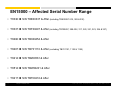
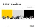
EN15000 – Service Manual October 2011 B U I L D I N G Caterpillar: Confidential Green C O N S T R U C T I O N P R O D U C T S EN15000 – Affected Serial Number Range • TH336 S/N TDE00337 & After (including TDE00297-318, 328 & 332) • TH337 S/N TDF00297 & After (including TDF00297, 299-302, 317, 320, 321, 323, 324 & 327) • TH406 S/N TBX00454 & After • TH407 S/N TBY01110 & After (excluding TBY01121, 1122 & 1128) • TH414 S/N TBZ00561 & After • TH514 S/N TBW00201 & After • TH417 S/N TBT00216 & After 2 Caterpillar: Confidential Green B U I L D I N G C O N S T R U C T I O N P R O D U C T S EN15000 – LSI-System Explanation • Introduction: – European (CE) telehandlers will be expected to comply with new regulations pertaining to the machine’s load moment or rear axle’s moment sensing system. The intention of the new regulation is to prevent longitudinal (forward) instability from occurring by reducing the machine’s function speeds before the 100% axle unloaded cutout point is reached. – These new regulations are part of the European Standard EN15000:2008. • Effective: – All machines produced after August 31st 2010 shall comply with the requirements of EN15000:2008. 3 Caterpillar: Confidential Green B U I L D I N G C O N S T R U C T I O N P R O D U C T S EN15000 – LSI-System Explanation • Requirements: – EN15000 compliant system requires electronic control of both the static and dynamic moments associated with load movement in the longitudinal forward machine axis as well as the cutout of the aggravating functions. This type of control has to be of a “redundant” type, and the new components in use will allow that. The norm applies to both construction and agricultural machines (static) and foresees that the cutout can be overridden temporarily and also that it can be deactivated when the boom is retracted. • Summary: – machine requires electronic control of both the static and dynamic moments associated with load movement in the longitudinal machine axis 4 Caterpillar: Confidential Green B U I L D I N G C O N S T R U C T I O N P R O D U C T S EN15000 – System is NOT: • Replacement for load chart • Substitute for operator training • Protection from lateral instability risks • Protection from backward instability risks 5 Caterpillar: Confidential Green B U I L D I N G C O N S T R U C T I O N P R O D U C T S EN15000 – Components • LSI Display (PRE- EN15000) CAT P/N:312-3331 6 Caterpillar: Confidential Green • LSI Display (EN15000) CAT P/N:377-9838 B U I L D I N G C O N S T R U C T I O N P R O D U C T S EN15000 – Components • LSI Sensor (PRE – EN15000) CAT P/N:320-9370 7 Caterpillar: Confidential Green • LSI Sensor (EN15000) CAT P/N:382-8745 B U I L D I N G C O N S T R U C T I O N P R O D U C T S EN15000 – Components • Fully Retract Switch (PRE – EN15000) TH406 TH417 • Requirements: – Not available on TH336, TH406, TH337 & TH407 TH406 TH417 • Requirements: – Standard on all models now • Platform Machines – Standard on Platform Machines • – Stabilizer & Boom Angle Operation Limitations Stabilizer & Boom Angle Operation Limitations • EN15000 Passive • 8 • Fully Retract Switch (EN15000) TH414, TH514 & TH417 Optional and/or Country Spec Caterpillar: Confidential Green B U I L D I N G C O N S T R U C T I O N P R O D U C T S EN15000 – Components • LSI Display – Machine “ON” status, small green LED in the “System Check” button. • LSI Display – Machine lifting a load, axle unloaded moment between 50 – 89.9% • 1st green LED: 50-59.9% • 2nd green LED: 60-69.9% • 3rd green LED: 70-79.9% • 4th green LED: 80-89.9% 9 Caterpillar: Confidential Green B U I L D I N G C O N S T R U C T I O N P R O D U C T S EN15000 – Components • LSI Display – Amber LED on; the rear axle unloaded percentage nearing trip point, but still within operable range 90-99.9%. If the amber LED comes on, the LED’s will flash simultaneously and an intermittent audible alarm will sound. 10 Caterpillar: Confidential Green • LSI Display – Red LED on; the rear axle unloaded percentage trip point (100% rated capacity) has been met or exceeded. All LED’s will flash simultaneously and a continuous audible alarm will sound. All aggravating movements are cut out. B U I L D I N G C O N S T R U C T I O N P R O D U C T S EN15000 – Fully Retracted Passive (All Models) TH336, TH337, TH406 & TH407 TH414 TH514 TH417 Boom Fully Retracted: - Sensor in the back of the boom is made (J3-8 is High) - No hydraulic cut-out, only audible and visible alarm in case of an overload condition - No speed reduction of boom movement 11 Caterpillar: Confidential Green B U I L D I N G C O N S T R U C T I O N P R O D U C T S EN15000 – Passive Mode TH336, TH337, TH406 & TH407 AND = EN15000 PASSIVE AND = EN15000 PASSIVE = EN15000 ACTIVE F R AND / N OR Passive Mode: The automatic function cutout and/or slow down feature is disabled, visual and audible alarm in event of an overload condition, when the machine is in Driving Mode or when the boom is fully retracted. No speed reduction of aggravating movement. Driving Mode: Parking Brake NOT applied AND shifter in Forward or Reverse (if one of the conditions is not met the system will be active) Passive Mode Indicator: Yellow LED above the LSI display is illuminated. 12 Caterpillar: Confidential Green B U I L D I N G C O N S T R U C T I O N P R O D U C T S EN15000 – Settings Explanation • LSI High Speed Current: Max. mA setting for boom down movement • LSI Low Speed Current: Max. mA setting for boom down movement when axle load percentage meets or exceeds 70% after evaluation period • LSI Creep Speed Current: Max. mA setting for boom down movement when axle load percentage meets or exceeds 70% during evaluation period • Ramp to High Speed Time: Required time to ramp up from LSI LOW Speed Current to LSI High Speed Current for boom down after the evaluation period • Rear Axle Evaluation Time: Period that rear axle load percentage will be monitored after each initial boom down request greater than LSI LOW SPEED CURRENT. • Reset Point Percentage: Rear axle load percentage point to reset overload condition • Reset Point Debounce Time: Period that joystick must be in neutral position after Reset Point Percentage is passed to get max. allowed speed back (LOW or Creep Speed) in stable condition. • LMI-CAN Trip Point Percentage of Load: Trigger point for mA output (LOW or Creep). • LSI Low Speed Current (TELE):Max. mA setting for TELE OUT movement when axle load percentage exceeds 70% after evaluation period • Ramp to High Speed Time (TELE): Required time to ramp up from LSI LOW Speed Current to LSI High Speed Current for TELE OUT movement after the evaluation period • High Speed Current (EN15000 passive): 13 Caterpillar: Confidential Green Max. mA setting for boom down movement when the boom is fully retracted and so the EN15000 LSI system is passive. B U I L D I N G C O N S T R U C T I O N P R O D U C T S EN15000 – Settings TH336, TH337, TH406 & TH407 LSI High Speed Current LSI Low Speed Current LSI Creep Speed Current Ramp to High Speed Time Rear Axle Evaluation Time TH336 & TH406 1580 mA 1070 mA 900 mA 2.5 sec 1.5 sec TH337 & TH407 1580 mA 1110 mA 900 mA 2.5 sec 1.5 sec Reset Point Percentage Reset Point Debounce Time LMI-CAN Trip Point Percentage of Load LSI Low Speed Current (TELE) Ramp to High Speed Time (Tele) TH336 & TH406 90% 1.0 sec 70% 1180 mA 1.5 sec TH337 & TH407 90% 1.0 sec 70% 1180 mA 1.5 sec High Speed Current – Fully Retracted (EN15000 PASSIVE) 14 TH336 & TH406 1600 mA TH337 & TH407 1600 mA Caterpillar: Confidential Green B U I L D I N G C O N S T R U C T I O N P R O D U C T S EN15000 – Settings TH414, TH514 & TH417 LSI High Speed Current LSI Low Speed Current LSI Creep Speed Current Ramp to High Speed Time Rear Axle Evaluation Time TH414 1310 mA 1110 mA 950 mA 3.0 sec 2.0 sec TH514 1570 mA 1270 mA 950 mA 3.0 sec 2.0 sec TH417 1330 mA 1150 mA 950 mA 3.0 sec 2.0 sec Reset Point Percentage Reset Point Debounce Time LMI-CAN Trip Point Percentage of Load LSI Low Speed Current (TELE OUT) Ramp to High Speed Time (TELE OUT) TH414 85% 1.5 sec 70% 1180 mA 2.0 sec TH514 85% 1.5 sec 70% 1300 mA 2.0 sec TH417 85% 1.5 sec 70% 1300 mA 2.0 sec High Speed Current – Fully Retracted (EN15000 PASSIVE) 15 TH414 1600 mA TH514 1600 mA TH417 1600 mA Caterpillar: Confidential Green B U I L D I N G C O N S T R U C T I O N P R O D U C T S EN15000 – Rear Axle Evaluation Time Rear Axle Evaluation Time starts after each initial joystick movement greater than LSI Low Speed Output Current Joystick Deflection 1310mA 1110mA 1048mA Ramp Up Time Rear Axle Evaluation Time 100% 80% Scenario 2 Scenario 1 Time Example: TH414 LSI High Speed Current = 1310mA LSI Low Speed Current = 1110mA 0% Joystick Deflection = 0mA Output Demand 100% Joystick Deflection = 1310mA Demand < 85% Joystick Deflection = No evaluation Time (Example: 1310mA x 80% = 1048mA) NOTE: FIGURES AND GRAPHS JUST AS REFERENCE! 16 Caterpillar: Confidential Green B U I L D I N G C O N S T R U C T I O N P R O D U C T S EN15000 – LSI Creep Speed Current LSI Creep Speed Current is the max. output current in case the rear axle unload percentage is greater or exceeds 70% during the rear axle evaluation time. Rear Axle Load (%) 100 85 70 Time Output Current(mA) High - 1310 Low - 1110 Creep - 950 Scenario 1 0 2 sec Eval. Time Scenario 2 0 2 sec Time Eval. Time Example: TH414 LSI Low Speed Current = 1110mA LSI Creep Speed Current = 950mA NOTE: FIGURES AND GRAPHS JUST AS REFERENCE! 17 Caterpillar: Confidential Green B U I L D I N G C O N S T R U C T I O N P R O D U C T S EN15000 – Overload Condition • Overload Condition – All Led's are flashing, continuous alarm – Hydraulic functions are locked out, except boom raise, boom retract and hydraulic QC (Australia = boom raise also locked out). • Re-engage aggravating movements Requirements: an “a” or “b” percentage of the rear axle load and a neutralization of the joystick for “x” or “y” seconds. – Raise or retract the boom, rear axle load reset points after overload • Rear Axle Load 90% => TH336, TH406, TH337 & TH407 [a] • Rear Axle Load 85% => TH414, TH514 & TH417 [b] – LED’s stop blinking after return to safe condition – Joystick must be in neutral position after return to safe condition for “x” or “y” seconds which is called the Reset Point Debounce Time. • Reset Point Debounce Time 1 second => TH336, TH406, TH337 & TH407 [x] • Reset Point Debounce Time 1.5 second => TH414, TH514 & TH417 [y] • Override the system – LSI Override Button: Momentarily disables the automatic function cut-out. LED flashes while activated. Depress and hold up to 30 seconds while operating joystick to momentarily disable the automatic function cutout. LSI Override Button 18 Caterpillar: Confidential Green B U I L D I N G C O N S T R U C T I O N P R O D U C T S Boom Down – TH414 -1800kg – Fully Retracted BOOM FULLY RETRACTED = EN15000 LSI SYSTEM PASSIVE (No cut-out, only LED’s & audible alarm) Rear Axle Load (%) 100 85 70 Output Current(mA) 1600 Time High Speed (EN15000 Passive) 0 Time NOTE: FIGURES AND GRAPHS JUST AS REFERENCE! 19 Caterpillar: Confidential Green FULL JOYSTICK DOWN DEFLECTION B U I L D I N G C O N S T R U C T I O N P R O D U C T S Boom Down – TH414 -1800kg – 0.5m Extension Rear Axle Load (%) 100 85 70 Time Output Current(mA) LSI High Speed (EN15000 Active) 1310 1110 LSI Low Speed (EN15000 Active) 0 2 sec 5 sec Time Ramp Up Time Eval. Time NOTE: FIGURES AND GRAPHS JUST AS REFERENCE! 20 Caterpillar: Confidential Green FULL JOYSTICK DOWN DEFLECTION B U I L D I N G C O N S T R U C T I O N P R O D U C T S Boom Down – TH414 -1800kg – 1.5m Extension Rear Axle Load (%) 100 85 70 Time Output Current(mA) LSI High Speed (EN15000 Active) 1310 1110 LSI Low Speed (EN15000 Active) 0 2 sec LSI Low Speed (EN15000 Active) 5 sec Time Ramp Up Time Eval. Time NOTE: FIGURES AND GRAPHS JUST AS REFERENCE! 21 Caterpillar: Confidential Green FULL JOYSTICK DOWN DEFLECTION B U I L D I N G C O N S T R U C T I O N P R O D U C T S Boom Down – TH414 -1800kg – 3.0m Extension Rear Axle Load (%) 100 85 70 Time Output Current(mA) LSI High Speed (EN15000 Active) 1310 1110 LSI Low Speed (EN15000 Active) LSI Low Speed (EN15000 Active) Aggravating Movements Locked Out 0 2 sec 5 sec Time Ramp Up Time Eval. Time NOTE: FIGURES AND GRAPHS JUST AS REFERENCE! 22 Caterpillar: Confidential Green FULL JOYSTICK DOWN DEFLECTION B U I L D I N G C O N S T R U C T I O N P R O D U C T S EN15000 - Components • Rear Axle Unloaded Moment Percentage Push C + OK for 2 seconds to enter analyzer menu 23 Caterpillar: Confidential Green B U I L D I N G C O N S T R U C T I O N P R O D U C T S EN15000 – Electrical Overview 24 Caterpillar: Confidential Green B U I L D I N G C O N S T R U C T I O N P R O D U C T S EN15000 – Sensor Testing B A C To check both cells of the LSI Sensor, connector SN213 of the LSI sensor needs to be disconnected. The position of connector is model specific so can be different as shown on the picture. Supply 12 Volt to pin B of the LSI sensor connector. Connect the COM line of the multimeter to Ground SN213 Connect multimeter to pin A, to measure cell 1 Connect multimeter to pin C, to measure cell 2 If the current (DC) of both cells is in the range of 50mA +/- 10mA, the sensor is working. Ensure the machine is on level ground, tires straight and the boom down, fully retracted and without load when you take the measurements. 25 Caterpillar: Confidential Green B U I L D I N G C O N S T R U C T I O N P R O D U C T S EN15000 – Sensor and Harness Testing +12V loop between pin 1 + 6 To check both cells of the LSI Sensor and the harness towards the LSI display, connector GD84 of the LSI Display needs to be disconnected. Cell 1 Create a loop of the +12 Volt line between pin 1 and 6 of connector GD84. Cell 2 Ensure the key switch is in position 1. Connect the COM line of the multimeter to pin 2 Connect multimeter to pin 4, to measure cell 1 Connect multimeter to pin 5, to measure cell 2 If the current (DC) of both cells is in the range of 50mA +/- 10mA, the sensor is working and the harness from the LSI sensor to the LSI display is ok. GD84 Ensure the machine is on level ground, tires straight and the boom down, fully retracted and without load when you take the measurements. 26 Caterpillar: Confidential Green B U I L D I N G C O N S T R U C T I O N P R O D U C T S EN15000 – Error Code 2560 • 2560 -> Boom Retract Sensor Faulty – Sensing Invalid • The UGM has detected any information on input J3-8 Boom Retracted is invalid or the system is set if the boom is always extended or retracted. • The UGM has detected one of the following failures of the boom retract sensor when configured for LSI-CAN or LSI-CAN + LMI: – With no telescope functions active, a boom retract sensor state change occurs after a 1000ms telescope function state change expires. – With TELESCOPE IN active, a boom retract sensor transition of HIGH to LOW occurs after a 1000ms telescope function state change expires. – With TELESCOPE OUT active, a boom retract sensor transition of LOW to HIGH occurs after a 1000ms telescope function state change expires. – With TELESCOPE OUT active, the boom retract sensor has not HIGH for a period of 5 seconds with at least 950mA commanded on the function AND the Load Moment Warning Point has been met or exceeded. • Power needs to be cycled. If error code is still present, boom retract sensor needs to be inspected for contamination and mounting integrity. 27 Caterpillar: Confidential Green B U I L D I N G C O N S T R U C T I O N P R O D U C T S EN15000 – Error Code 8514 • 8514 -> LSI NOT CALIBRATED • LSI System not calibrated. • The LSI System is reporting it does not have a valid calibration. This situation should only occur at the factory and when LSI display has been replaced in the field. This condition will be satisfied once the LSI System has successfully been calibrated. 28 Caterpillar: Confidential Green B U I L D I N G C O N S T R U C T I O N P R O D U C T S EN15000 – Error Code 8515 • 8515 -> LSI DETECTED BUT NOT CONFIGURED • The UGM has detected the LSI System is connected but not configured. • The UGM is reporting the EN15000 LSI System is installed however it has not been configured properly. The machine has either been configured as an ANSI unit or LOAD MOMENT menu has been set to LSI or LMI. Either remove the LSI System or correct the configuration selection under the MACHINE SETUP menu. 29 Caterpillar: Confidential Green B U I L D I N G C O N S T R U C T I O N P R O D U C T S EN15000 – Error Code 8516 / 8517 • 8516 -> LSI LOAD CELL A – OUT OF RANGE AND/OR 8517 -> LSI LOAD CELL B – OUT OF RANGE • LSI System is out of range (LOW side). • The LSI System is reporting it sees one or both of the load cells out of range on the low side of the expected operating range. In the majority of cases, this is typically caused by a wiring issue. Start by evaluating the wiring of the 3-pass connector at the load cell. Next, disconnect the LSI display and perform a continuity check of the LSI cable running from the display to the sensor. If the wires all check out and are located in the proper connector position, check the crimps of the respective wire in the LSI display. Next, visually inspect the sensor for damage. Verify the LSI Sensor is still secured to the axle at 60-70 N-m. If the bolt turns the torque is incorrect and the machine must undergo a field calibration. If the torque setting is correct, replace the LSI Sensor and perform a field calibration. 30 Caterpillar: Confidential Green B U I L D I N G C O N S T R U C T I O N P R O D U C T S EN15000 – Error Code 8516 / 8517 • 8516 -> LSI LOAD CELL A – OUT OF RANGE AND/OR 8517 -> LSI LOAD CELL B – OUT OF RANGE • LSI System is out of range (HIGH side). • The LSI System is reporting it sees one or both of the load cells out of range on the high side of the expected operating range. In the majority of cases, this is typically caused by a wiring issue. Start by evaluating the wiring of the 3-pass connector at the load cell. Next, disconnect the LSI display and perform a continuity check of the LSI cable running from the display to the sensor. If the wires all check out and are located in the proper connector position, check the crimps of the respective wire in the LSI display. Next, visually inspect the sensor for damage. Verify the LSI Sensor is still secured to the axle at 60-70 N-m. If the bolt turns the torque is incorrect and the machine must undergo a field calibration. If the torque setting is correct, replace the LSI Sensor and perform a field calibration. 31 Caterpillar: Confidential Green B U I L D I N G C O N S T R U C T I O N P R O D U C T S EN15000 – Error Code 8518 • 8518 -> LSI CUTOUT OUTPUT – SHORT TO BATTERY OR OPEN CIRCUIT • LSI System’s digital output is not responding as expected. • The LSI System is reporting the LSI Display has determined that a open circuit or short to battery condition exists on its output signal pin (3). Pin 3 of the LSI Display connects to the UGM input J4-10. In the majority of cases, this is typically caused by a wiring issue. Start by checking the connections at both ends and then perform a continuity check. Note, if the machine is fitted with a 3B6 system, it also provides as parallel signal to UGM input J4-10 and could be the cause of the issue. If everything check out, then most likely there has been internal damage to LSI Display and it should be replaced; then perform a LSI field calibration procedure. 32 Caterpillar: Confidential Green B U I L D I N G C O N S T R U C T I O N P R O D U C T S EN15000 – Error Code 8519 • 8519 -> LSI OUT OF CALIBRATION • The LSI-CAN Check Points have not been calibrated or failed a check with the UGM. • The UGM is reporting the LSI-CAN Check Points either have not been entered after a LSI System calibration or during the LSI check the actual load cell raw counts are not within +/- 10 counts of the logged calibrated counts. The most likely event is the machine is either not on level ground or the machine is not in the proper configuration for running the test.Also, if the UGM were to be replaced in the field, the UGM logged LSI-CAN check points will need to be re-entered in the CALIBRATIONS menu. Once this has been completed, the LSI-CAN check point test in the OPERATOR TOOLS menu will need to be performed. • The LSI System does not need to be calibrated. The UGM just needs the information from the LSI System so the UGM can perform the a system integrity check. 33 Caterpillar: Confidential Green B U I L D I N G C O N S T R U C T I O N P R O D U C T S EN15000 – Error Code 99151 • 99151 -> FUNCTIONS LOCKED OUT – LSI SOFTWARE VERSION IMPROPER • The UGM has determined the LSI Display is not an acceptable software version. • Replace the LSI Display and perform the field calibration procedure. 34 Caterpillar: Confidential Green B U I L D I N G C O N S T R U C T I O N P R O D U C T S EN15000 – Error Code 99152 • 99152 -> LSI FAULTY – SYSTEM FLASH CRC ERROR • The LSI System has an internal error. • Replace the LSI Display and perform the field calibration procedure 35 Caterpillar: Confidential Green B U I L D I N G C O N S T R U C T I O N P R O D U C T S EN15000 – Error Code 99153 • 99153 -> LSI FAULTY – DATA FLASH CRC ERROR • The LSI System has an internal error. • Replace the LSI Display and perform the field calibration procedure 36 Caterpillar: Confidential Green B U I L D I N G C O N S T R U C T I O N P R O D U C T S EN15000 – Error Code 99154 • 99154 => LSI FAULTY – LOAD CELLS A AND B DISAGREEMENT • 10% sensing current difference between load cells. • The LSI System is reporting it is seeing a 10% sensing current difference between the load cells. In the majority of cases, this is typically caused by a wiring issue. Start by evaluating the wiring of the 3-pass connector at the load cell. Next, disconnect the LSI display and perform a continuity check of the LSI cable running from the display to the sensor. If the wires all check out and located in the proper connector position, check the crimps of the respective wire in the LSI display. Next, visually inspect the sensor for damage. Verify the LSI Sensor is still secured to the axle at 60-70 N-m. If the bolt turns the torque is incorrect and the machine must undergo a field calibration. If the torque setting is correct, replace the LSI Sensor and perform a field calibration. 37 Caterpillar: Confidential Green B U I L D I N G C O N S T R U C T I O N P R O D U C T S EN15000 – Field Calibration Procedure Go to Section 9.16 of Service Manual 31200370 Rev. F (or later) 38 Caterpillar: Confidential Green B U I L D I N G C O N S T R U C T I O N P R O D U C T S