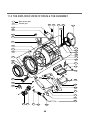
1
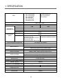
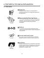
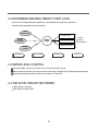
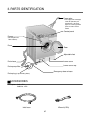
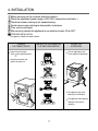
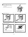
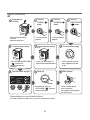
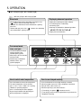
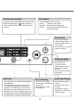
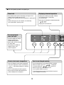
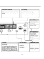
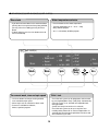
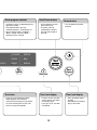
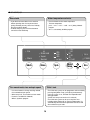
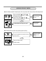
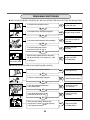
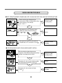
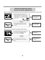
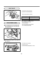
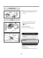
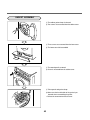
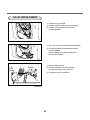
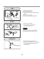
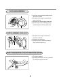
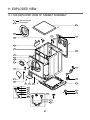
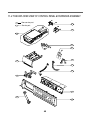
website : http://www.LGEservice.com
e-mail : http://LGEservice.com/techsup.html
WASHING MACHINE
SERVICE MANUAL
CAUTION
READ THIS MANUAL CAREFULLY TO DIAGNOSE TROUBLE
CORRECTLY BEFORE OFFERING SERVICE.
MODEL : WD-803(4)0(W)(F)(H)
WD-803(4)0F(H)(B)
WD-1042F(H)(B)
WD-1041(3)F(H)(B)
WD-102(4)1(5)W(F)(H)
WD-102(4)(5)F(H)(B)
WD-1223(5)F(H)(B)
WD-1243(5)F(H)(B)
JUN. 2001 PRINTED IN KOREA
P/No.:3828ER3008A
CONTENTS
1. SPECIFICATION............................................................................................................................3
2. FEATURES & TECHNICAL EXPLANATION ................................................................................ 4
3. PARTS IDENTIFICATION ............................................................................................................ 6
4. INSTALLATION ............................................................................................................................. 7
5. OPERATION ................................................................................................................................10
6. WIRING DIAGRAM .....................................................................................................................18
7. PROGRAM CHART .....................................................................................................................19
8. TROUBLESHOOTING.................................................................................................................20
8-1. BEFORE PERFORMING SVICE ........................................................................................20
8-2. QC TEST MODE.................................................................................................................20
8-3. HOW TO KNOW THE WATER LEVEL FREQUENCY........................................................21
8-4. ERROR DISPLAY ...............................................................................................................22
9. ERROR DIAGNOSIS AND CHECK LIST ....................................................................................26
9-1. DIAGNOSIS AND ANSWER FOR ABNORMAL OPERATION ...........................................26
9-2. FAULT DIAGNOSIS AND TROUBLESHOOTING ..............................................................29
10. DISASSEMBLY INSTRUCTIONS .............................................................................................39
11. EXPLODED VIEW AND PART LIST ..........................................................................................47
11-1. THE EXPLODED VIEW OF CABINET ASSEMBLY..........................................................47
11-2. THE EXPLODED VIEW OF CONTROL PANEL & DISPENSER ASSEMBLY ..................48
11-3. THE EXPLODED VIEW OF DRUM & TUB ASSEMBLY...................................................49
APPENDIX(Replacement parts list) ........................................................................................... 50
2
1. SPECIFICATION
WD-1223(5)F(H)(B)
WD-1243(5)F(H)(B)
WD-1041(3)F(H)B
WD-1042F(H)B
WD-102(4)1F(H)B
WD-803(4)0F(H)B
ITEM
POWER SUPPLY
PRODUCT WEIGHT
WASHING
ELECTRICITY
CONSUMPTION
WD-803(4)0(W)(F)(H)
WD-102(4)1W(F)(H)
WD-1042F(H)
220V - 240V~, 50Hz
63kg
67kg
120W
190W
SPIN (800rpm)
300W
DRAIN MOTOR
32W
WASH HEATOR
2000W
REVOLUTION
SPEED
WASH
SPIN
45 rpm
600/800/1000 rpm
600/800/1000/1200 rpm
400/600/800/1000 rpm
No Spin/500/800 rpm[WD-803(4)0(W)(F)(H)]
[WD-1041(3)F(H)B / WD-1042F(H)B /
WD-102(4)1(5)F(H)B]
No Spin/500/800 rpm[WD-803(4)0F(H)B]
OPERATION WATER PRESSURE
0.3-10kgf/cm2 (30-1000kPa)
CONTROL TYPE
Electronic
7.0kg
WASH CAPACITY
Wool (2.0kg), Synthetic (4.0), Delicate (3.0kg)
DIMENSION
WASH PROGRAM
600mm (W) x 600mm (D) x 850mm (H)
Coloreds, Whites, Rapid, Synthetic, Wool, Delicate
Normal, Super, Normal+Rinse Hold,
RINSE PROGRAM
Super+Rinse Hold
DOOR SWITCH TYPE
Automatic type by pressing the button
WATER LEVEL
9 steps (by sensor)
SENSING OF THE LAUNDRY AMOUNT
Adapted
NEURO - FUZZY
Adapted
DISPLAY OF THE REMAINING TIME
Adapted
DIAGNOSIS ERROR
10 ITEMS
7 ITEMS
POWER AUTO OFF
Adapted
AUTO RESTART
Adapted
CHILD LOCK
Adapted
3
2. FEATURES & TECHNICAL EXPLANATION
2-1.FEATURES
Jumbo drum
40%
Jumbo drum can wash about 40% more per load than
conventional washing machine. A bigger drum improves the
wash performance.
More economical by Fuzzy Logic System
FUZZY Logic System detects the amount of load and water
temperature, and then determines the optimum water level
and washing time to minimize energy and water
consumption.
Child-Lock
(Water Temp)
(Time Delay)
The Child-Lock system has been developed to prevent
children from pressing any button to change the programme
during operation.
Low noise speed control system
By sensing the amount of load and balance, automatical
distributes load evenly to minimize the spinning noise level.
Auto Restart
Although the washing machine is turned off by a power failure,
it restarts automatically where it stopped process when power
is supplied again. It will be the same when the machine is
unplugged and is plugged in again.
4
2-2.DETERMINE WASHING TIME BY FUZZY LOGIC
To get the best washing performance optimal time is determined by sensing of water temperature,
selected washing temperature and laundry amount.
water
temperature
washing time
selected
washing
temperature
FUZZY
LOGIC
rinse time
the best
washing
performance
spin rhythm, time
laundry
amount
SENSING
PROCESSING
DETERMINATION
EFFECT
2-3.WATER LEVEL CONTROL
This model adopts a pressure sensor which can sense the water level in the tub.
When the water level reaches to the preset level the water supply is stopped, then the washing program proceeds.
Spinning does not proceed until the water in the tub reduces a certain level.
2-4.THE DOOR CAN NOT BE OPENED
While program is operating.
While Door Lock light turns on.
5
3. PARTS IDENTIFICATION
Power plug
• If the supply cord is damaged,
it must be replaced by the
manufacturer or its service
agents or a similarly qualified
person in order to avoid a
hazard.
Control panel
Drawer
(For detergent and
fabric softener)
Drum
Door
Adjustable feet
Drain hose
Lower cover
Drain pump filter
Lower cover cap
Emergency door release
Drain plug (Cap,Remaing Hose)
ACCESSORIES
* Option : Cold - 1EA
Cold/Hot - 2EA
Wrench(1EA)
Inlet hose
6
4. INSTALLATION
Before servicing ask the customer what the trouble is.
Check the adjustment (power supply is 220-240V, remove the transit bolts....)
Check the troubles referring to the troubleshooting.
Decide service steps referring to disassembly instructions.
Then, service and repair.
After servicing, operate the appliance to see whether it works O K or NOT.
STANDARD INSTALLATION
The appliance should be installed as follows.
REMOVE
THE TRANSIT BOLTS
INSTALL THE APPLIANCE ON
FLAT AND FIRM SURFACE
ADJUST THE
HORIZONTAL
Remove the transit bolts
(4EA: ) with supplied spanner.
Turn the adjustable feet to
set the appliance horizontally.
Keep the transit bolts and
spanner for future use.
Low
High
The appliance goes up by
rotating the feet clockwise.
The appliance comes down by
1
rotating the feet counterclockwise.
7
HOW TO CONNECT INLET HOSE
Check that the rubber washer is inside of the
valve connector.
Connect the inlet hose firmly to prevent leak.
CONNECT DRAIN HOSE
Make sure that the hose is not twisted.
Avoid submerging the end of the hose.
The drain hose should be placed under 100cm from the floor.
CONNECT POWER PLUG
Avoid connecting several electric devices,
It may be the cause of a fire.
Connect the power plug to the wall outlet.
8
TEST OPERATION
Preparation for
washing.
Press the
POWER (
button.
)
Press the
PROGRAM (
button.
P
)
Press the
(START/PAUSE)
(
) button.
P
Connect the power plug to
the outlet.
Connect the inlet hose.
·In case of coloreds
program.
Check the water heating.
·Press the button (WATER TEMP)
(
) and then the
present temperature in
displayed.
Check the drain and spin
Pre
Main
(Wash)
Rinse hold
Super
Normal
(Rinse)
·In case of coloreds
program.
Check automatic reverse
turn.
·Check if the drum rotates to
clockwise and counterclockwise.
Power off
Check the water supply.
·Check shower because the
water supplied on the door
at first.
Water removal
1200
1000
800
600
no Spin
(Spin)
·After power off, press the
DOOR OPEN (
) button to
check the door open.
Troubleshooting refer to (8-4.ERROR DISPLAY)
Assemble and disassemble refer to (10.Disassembly Instructions)
9
·If SVC is needed, during
check and remove
the remaining water by pulling
out the hose cap.
5. OPERATION
■ WD-1223(5)F(H)(B) / WD-1243(5)F(H)(B)
WD-1041(3)F(H)B / WD-102(4)1(5)F(H)B
Rinse hold
Displaying abnormal operation
• Rinse hold function can be selected by pressing the rinse
(
) button, and rinse hold lamp turns ON.
• Selection rinse hold washer waits without drain / spinning
after rinse.
• To drain and spin, press rinse (
) button, rinse hold lamp
turns off and drain / spinning starts.
• Display the remaining time (Hour : Minute)
• The remaining time is reduced by
the washing cycle.
• Error lamp is indicated the abnormal operation.
(
)
,
,
,
,
,
,
• Display the reservation time.
For manual wash,
rinse, and spin
• Use these buttons to change
washing method, rinse
method spinning speed.
• When lamp is off, no selection
has been made.
• Prewashing is available for
coloreds, whites, and
synthetic program.
Pre
R
1200(1000)
1000(800)
800(600)
600(400)
no Spin
H
S
Main
N
(Wash)
(Rinse)
(Spin)
95
60
T
T
50
40
30
Cold
(Water Temp)
(Time Delay)
How to set the Function
How to use delayed washing
How to select water temperature
• Press the button to select water temperature.
• The water temperature can be selected
[40°C→ 50°C→ 60°C→Cold→ 30°C ] during
coloreds, or synthetic programs.
• 95°C is selected only for whites program.
• By pressing the button while operating the
present temperature is displayed.
• Press the button when reservation washing is needed.
• When the button is pressed,`3:00ais displayed. A maximum
delay of`19:00ahours can be set.
• Whenever pressing it, one hour increases.
•~ Time delay ₩the power (
) button to cancel it.
•~ Time delay ₩means the time required from the present to the
completion of washing.
10
Error display
How to select a program
• 6 programs can be selected by the kind of the laundry.
• The display blinks if there is an error.
• no inlet
: Trouble with water supply.
• imbalance : The laundry is tilted to one side.
• no drain : The drain filter is clogged or the drain
pump is out of order.
• By pressing the program (
) button, [Coloreds→
Whites→Rapid→Delicate→Wool→Synthetic] can be
selected.
P
Power button
C
S
W
W
R
D
P
y)
• By pressing the button, it
repeats turning on and off.
• Press the button to cancel
the time delay.
• It turns off in 8 sec. after the
program is finished.
i
(Power)
Start/Pause button
(Start/Pause)
Door lock
(Program)
Child-Lock
• Once Child-Lock is set, all buttons are inoperable
during operation.
• The Child-Lock system can be set at any time
even including during Power Off, on Pause and
operation. It is automatically cancelled when an
operational error occur and when the cycle ends.
(Door open)
Door lock display
• It shows whether the door
can be open or not during the
washing cycle.
• If the lamp is off, the door
can be opened.
• When power is off, the LED indicates~
₩only.
During operation, or when the program paused the
LED Will indicate~
₩and the remaining time.
11
• Use the button to start or
pause wash cycle.
• The power turns off
automatically in 4 minutes
after the pause button is
pressed.
• Press the button to change
the program.
How to open the door
• Use the button to add the
laundry.
• Press the button to open
the door.
• Only operates when the
power plug is connected to
220-240V~ outlet.
■ WD-1021(5)W(F)(H)/WD-1041(5)W(F)(H)
Rinse hold
Displaying abnormal operation
• Rinse hold function can be selected by pressing the rinse
button, and rinse hold lamp turns ON.
• Selection rinse hold washer waits without drain / spinning after
rinse.
• To drain and spin, press rinse button, rinse hold lamp
turns off and drain / spinning starts.
• Display the remaining time (Hour : Minute)
• The remaining time is reduced by
the washing cycle.
• Error lamp is indicated the abnormal operation.
(
)
,
,
• Display the reservation time.
For manual wash,
rinse, and spin
• Use these buttons to change
washing method, rinse
method spinning speed.
• When lamp is off, no selection
has been made.
• Prewashing is available for
coloreds, whites, and
synthetic program.
Wash
Rinse
Spin
Water
Temp.
How to set the Function
How to use delayed washing
How to select water temperature
• Press the button to select water temperature.
• The water temperature can be selected [40°C
→ 60°C→ Cold ] during coloreds, or synthetic
programs.
• 95°C is selected only for whites program.
• By pressing the button while operating the
present temperature is displayed.
• Press the button when reservation washing is needed.
• When the button is pressed,`
ais displayed.
A maximum delay of`
ahours can be set.
• Whenever pressing it, one hour increases.
• Use the power button to cancel it.
•~ Time delay ₩means the time required from the present
to the completion of washing.
12
Ti
De
How to select a program
Error display
• 6 programs can be selected by the kind of the laundry.
• The display blinks if there is an error.
• no inlet
: Trouble with water supply.
• imbalance : The laundry is tilted to one side.
• no drain : The drain filter is clogged or the drain
pump is out of order.
• By pressing the program button, [Coloreds → Whites
→ Rapid → Delicate → Wool → Synthetic] can be
selected.
Power button
Power
• By pressing the button, it
repeats turning on and off.
• Press the button to cancel
the time delay.
• It turns off in 8 sec. after the
program is finished.
Start
Pause
Time
Delay
Door
Open
Program
Start/Pause button
Door lock
• Use the button to start or
pause wash cycle.
• The power turns off
automatically in 4 minutes
after the pause button is
pressed.
• Press the button to change
the program.
Child-Lock
• Once Child-Lock is set, all buttons are inoperable
during operation.
• The Child-Lock system can be set at any time
even including during Power Off, on Pause and
operation. It is automatically cancelled when an
operational error occur, and when the cycle ends.
Door lock display
• It shows whether the door
can be open or not during the
washing cycle.
• If the lamp is off, the door
can be opened.
• When power is off, the LED indicates~
₩only.
During operation, or when the program paused the
LED Will indicate~
₩and the remaining time.
13
How to open the door
• Use the button to add the
laundry.
• Press the button to open
the door.
• Only operates when the
power plug is connected to
220-240V~ outlet.
■ WD-8030(W)(F)(H)/WD-8040(W)(F)(H)/WD-1042F(H)
Water temperature selector
Rinse hold
Press the button to select water temperature.
If you desire to leave fabrics in the machine without
spinning after rinse to prevent them getting wrinkled,
you may select rinse Hold by pressing the Rinse
button.
The water temperature [40。C
during coloreds program.
60。C
cold]
95。C is selected only for White program.
To drain and spin, press the rinse button to turn off
the rinse Hold lamp.
16
WD-1042F(H)
Pre
Main
Wash
800
(1000)
Rinse Hold
Super
Normal
600
(800)
Rinse
Spin
For manual wash, rinse and spin speed
no Spin (600)
95 C
60 C
40 C
Cold
Eco
Water
Temp
Eco
Child lo
Child - lock
Use these buttons to change washing method,
rinse method and spin speed.
The Child Lock system can be programme and canceled
by pressing both~Water Temp.₩and~Eco₩simultaneously.
Once this system is set, all button are inoperable work
during operation.
(Child Lock Lamp is on on when it is selected.)
When lamp is off, no selection has been made.
Prewash is available for Coloreds,
Whites, Synthetic program.
The Child Lock system can be set at any time even
including during Power-Off on. Pause and operation. It is
automatically cancelled when operational error occur and
when end of the cycle ends.
14
Wash program selector
6 programs can be set depending on the
type of the laundry.
If the power button is pressed.
Coloreds program is automatically set.
By pressing the button, [ Coloreds
Whites Rapid Delicate Wool
Synthetic] can be selected.
d lock
Coloreds
Synthetic
Whites
Wool
Rapid
Delicate
Start/Pause button
Use the button to start or
pause wash cycle.
The power turns off
automatically 4 minutes
after the pause button is
pressed.
Power button
Press the button to turn power
on and off.
Start
Pause
Program
Door
Open
Door Lock
Eco button
If you press the Eco button in while
Whites program, Eco function is
selected. Eco function gives you almost
the same washing effect as that in 95
with less energy consumption.
Door lock display
It shows whether the door
can be open or not during
the washing cycle.
If the light is off, the door
can opened.
15
Door lock display
Press the button to open
the door.
Only operate when power
plug is connected.
■ WD-8030F(H)B
Water temperature selector
Rinse hold
Press the button to select water temperature.
The water temperature
[40。C 50。C 60。C cold 30。C] during Coloreds
program.
95。C is selected only for White program.
If you desire to leave fabrics in the machine
without spinning after rinse to prevent them
getting wrinkled, you may select rinse Hold by
pressing the Rinse button.
To drain and spin, press the Rinse button to
turn off the rinse Hold lamp.
16
Pre
Main
Wash
800
600
400
no Spin
Rinse Hold
Super
Normal
Rinse
For manual wash, rinse and spin speed
Spin
95
60
50
40
30
Cold
Water
Temp
Eco
Child lo
Eco
Child - lock
Use these buttons to change washing method,
rinse method and spin speed.
The Child Lock system can be programme and canceled by
pressing both~Water Temp.₩and~Eco₩simultaneously.
Once this system is set, all button are inoperable work
during operation.
(Child Lock Lamp is on on when it is selected.)
The Child Lock system can be set at any time even
including during Power-Off on. Pause and operation. It is
automatically cancelled when operational error occur and
when end of the cycle ends.
When lamp is off, no selection has been made.
Prewash is available for Coloreds,
Whites, Synthetic program.
16
Wash program selector
6 programs can be set depending on the
type of the laundry.
If the power button is pressed.
Coloreds program is automatically set.
By pressing the button, [ Coloreds
Whites Rapid Delicate Wool
Synthetic] can be selected.
d lock
Coloreds
Synthetic
Whites
Wool
Rapid
Delicate
Start/Pause button
Use the button to start or
pause wash cycle.
The power turns off
automatically 4 minutes
after the pause button is
pressed.
Power button
Press the button to turn power
on and off.
Start
Pause
Program
Door
Open
Door Lock
Eco button
If you push the Eco button in while
Whites program, Eco function is
selected. Eco function gives you almost
the same washing effect as that in 95
with less energy consumption.
Door lock display
It shows whether the door
can be open or not during
the washing cycle.
If the light is off, the door
can opened.
17
Door lock display
Press the button to open
the door.
Only operate when power
plug is connected.
6. WIRING DIAGRAM
■ WD-1223(5)F(H)(B) / WD-1243(5)F(H)(B) / WD-1041(2)(3)F(H)B
WD-102(4)1(5)F(H)B / WD-803(4)0F(H)B
GN/YL(GN)
GN/YL(GN)
GN/YL(GN)
GN/YL(GN)
■ WD-803(4)0(W)(F)(H) / WD-102(4)1(5)W(F)(H) / WD-1042F(H)
(option)
18
7. PROGRAM CHART
■ WD-8030(4)(W)(F)(H) / WD-102(4)1(5)W(F)(H) / WD-1042F(H) / WD-1223(5)F(H)(B)
WD-1243(5)F(H)(B)
About 2:23
About
45
About
41
■ WD-1041(3)F(H)B/803(4)0F(H)B/102(4)2F(H)B/102(4)5F(H)B
About 1:07
19
8. TROUBLESHOOTING
8-1.BEFORE PERFORMING SERVICE
■ Be careful of electric shock or disconnecting the parts while troubleshooting.
■ Voltage of each terminal in AC 220-240V and DC while applying an electric current.
8-2.QC TEST MODE.
① Pressing RINSE (
), and SPIN (
) button simultaneously.
② Power supply ON with pressing upper two button. then buzzer sound twice.
③ Press the START/PAUSE (
~Press the START/PAUSE (
) button as follows.
) button more 4 times until stop spinning₩
■ WD-1223(5)F(H)(B) / WD-1243(5)F(H)(B) / WD-102(4)1(5)W(F)(H)
WD-102(4)1(5)F(H)B / WD-1041(3)F(H)B
Pressing number of
Checking Point
[START/PAUSE]button
None
All lamps turn on
Display Status
1 time
Clockwise spin (right)
Motor rpm (About 45)
2 times
Low speed spin
Motor rpm (About 63~67)
3 times
High speed spin
Motor rpm (About 114~117)
4 times
Inlet valve for pre-wash operation
Water level frequency (25~65)
Inlet valve for main-wash operation
5 times
Water level frequency (25~65)
Hot inlet valve in case of hot water fill
6 times
Inlet valve for main-wash operation
Water level frequency (25~65)
7 times
Counterclockwise spin (left)
Motor rpm (About 45)
8 times
A Heater is in operation for 3 sec.
Water Temperature
9 times
Draining pump operation
Water level frequency
10 times
Auto off operation
20
■ WD-803(4)0(W)(F)(H) / WD-803(4)0F(H)(B) / WD-102(4)2F(H)(B)
Checking Point
Times of press
None
All lamps turn on
1 time
Counterclockwise spin
2 times
Low speed Spin
3 times
High speed Spin
4 times
Inlet valve for pre-wash operation (Cold)
5 times (FOR WD-****FH)
Inlet valve for main-wash operation (Hot)
6 times
Inlet valve for main-wash operation (Cold)
7 times
Clockwise spin
8 times
The Heater is in operation for 3 sec.
9 times
Draining pump operation
10 times
Auto off operation
8-3. HOW TO KNOW THE WATER LEVEL FREQUENCY
■ WD-1223(5)F(H)(B)/WD-1243(5)F(H)(B)/WD-102(4)1(5)W(F)(H) / WD-1041(3)F(H)B
Press the WASH and RINSE button simultaneously.
The digits means water level frequency (10-1 ㎑)
ex) 241 : Water level frequency = 241× 10-1㎑
= 24.1㎑
21
8-4. ERROR DISPLAY.
■ WD-1223(5)F(H)(B)/WD-1243(5)F(H)(B)/WD-102(4)1(5)WF(H) / WD-1041(3)F(H)B
If you press the~Start/Pause₩
button when an error in displayed, any error except
will disappear and the machine will change into pause status.
In case ofd e,d e,d e, if the error is not resolved within 20 sec. In the case of other errors,
if the error is not resolved within 4 min. power will be turned off automatically and the error code will blink.
But in case ofdFEe, power will not be turned off.
ERROR
1
SYMPTOM
WATER INLET
ERROR
CAUSE
Water has not reached to the pre-set level within 4 min. since
no inlet
inlet valve operated, or water has not reached to the normal
level within 25 min.
2
IMBALANCE
imbalance
ERROR
The appliance is tilted.
Laundry is gathered to one side.
Non-distributable things are put into the drum.
3
DRAIN ERROR
4
OVERFLOW
ERROR
5
no drain
Water has not drained enough within 5 min.
Water is automatically being pumped out because too much
water is in the tub.
SENSOR PRESSURE
The sensor pressure switch is out of order.
S/W ERROR
6
DOOR OPEN
ERROR
7
HEATING
The~Start/Pause₩
button is pressed with the door open.
The door switch is out of order.
The thermistor is out of order.
ERROR
8
SENSOR
ERROR
The connector (5-pin, male, white) in the wire harness is not
connected to the connector (5-pin, female) of hall sensor in
the MOTOR.
’ Reconnect or repair the contact in the connector.
22
ERROR
8
SENSOR
ERROR
9
CURRENT
ERROR
10
LOCK
ERROR
SYMPTOM
CAUSE
• The electric contact between the connectors
(5-pin, male in the wire harness and 5-pin female in the hall sensor)
is bad or unstable.
Reconnect or repair the contact in the connector.
• The connector (6-pin, male, natural) in the wire harness is not
connected to the connector (6-pin, female, natural) of PWB assembly
(Main) or the electric contact of connectors is bad/unstable.
Reconnect or repair the contact in the connector.
• The electric contact between the connectors~6-pin, male in the wire
harness and 6-pin female in the controller (Main)₩is bad or unstable.
Reconnect or repair the contact in the connector.
• The wire harness between hall sensor in the MOTOR and PWB
assembly (Main) is cut (open circuited).
Repair/replace the damaged WIRE HARNESS.
• The hall sensor is out of order/defective.
Replace the motor.
• The controller (Main) is out of order/defective.
Replace the PWB assembly (Main).
• PWB assembly (Main) is out of order.
Replace the PWB assembly (Main).
• Winding in the MOTOR is short-circuited.
Replace the MOTOR.
• The connector (3-pin, male, white) in the wire harness is not connected
to the connector (3-pin, female, white) of MOTOR.
Reconnect or repair the connector.
• The electric contact between the connectors~3-pin, male, white in the
wire harness and 6 pin, female, white in the PWB assembly (Main)₩
is bad or unstable.
Reconnect or repair the contact in the connector.
• The wire harness between the MOTOR and PWB assembly (Main)
is cut (open circuited).
Repair the damaged (open-circuited) WIRE HARNESS.
• The hall sensor is out of order/defective.
Replace the PWB assembly (Main).
23
■ WD-8030(W)(F)(H)/WD-8040W(F)(H)/WD-1042F(H)/WD-803(4)0F(H)B/WD-102(4)2F(H)B
If you press the~Start/Pause₩button when an error in displayed, any error except
SENSOR PRESSURE S/W ERROR will disappear and the machine will change into pause status.
In case ofdSENSOR PRESSURE S/W ERROR, THERMISTOR ERROReif the error is not resolved
within 20 sec. In the case of other errors, if the error is not resolved within 4 min. power will be turned
off automatically and the error code will blink. But in case ofdOVER FLOW ERRORe, power will not
be turned off.
ERROR
1
2
3
WATER INLET
ERROR
SYMPTOM
Main
IMBALANCE
ERROR
Rinse Hold
Super
Normal
DRAIN ERROR
800
(1000)
600
(800)
no Spin (600)
4
OVERFLOW
ERROR
5
SENSOR PRESSURE
S/W ERROR
6
7
Water has not reached to the pre-set level within 4 min. since
inlet valve operated, or water has not reached to the normal
level within 25 min.
Pre
1000
800
600
400
no spin
DOOR OPEN
ERROR
CAUSE
The appliance is tilted.
Laundry is gathered to one side.
Non-distributable things are put into the drum.
Water has not drained enough within 5 min.
※( ) :WD-1042F(H)
for
WD-8030F(H)B
WD-8040F(H)B
WD-1022F(H)B
WD-1042F(H)B
Water is automatically being pumped out because too much
water is in the tub.
Coloreds
Whites
Rapid
Synthetic
The sensor pressure switch is out of order.
Wool
Delicate
Door Lock
THERMISTOR
ERROR
95 C
60 C
40 C
Cold
50
95
60
40
30
Cold
The Start/Pause button is pressed with the door open.
The door switch is out of order.
The thermistor is out of order.
for
WD-8030F(H)B
WD-8040F(H)B
WD-1022F(H)B
WD-1042F(H)B
24
ERROR
8
SENSOR
ERROR
SYMPTOM
Rinse Hold
Super
Normal
(1000)
800
600
400
no spin
for
WD-8030F(H)B / WD-8040F(H)B
WD-1022F(H)B / WD-1042F(H)B
9
CURRENT
ERROR
Pre
Main
Rinse Hold
Super
Normal
for
WD-8030F(H)B / WD-8040F(H)B
WD-1022F(H)B / WD-1042F(H)B
10
LOCK
ERROR
(1000)
800
600
400
no spin
95
60
50
40
30
Cold
for
WD-8030F(H)B / WD-8040F(H)B
WD-1022F(H)B / WD-1042F(H)B
CAUSE
• The electric contact between the connectors
(5-pin, male in the wire harness and 5-pin female in the hall sensor) is
bad or unstable.
Reconnect or repair the contact in the connector.
• The connector (6-pin, male, natural) in the wire harness is not connected
to the connector (6-pin, female, natural) of PWB assembly (Main) or the
electric contact of connectors is bad/unstable.
Reconnect or repair the contact in the connector.
• The electric contact between the connectors~6-pin, male in the wire
harness and 6-pin female in the controller (Main)₩is bad or unstable.
Reconnect or repair the contact in the connector.
• The wire harness between hall sensor in the MOTOR and PWB
assembly (Main) is cut (open circuited).
Repair/replace the damaged WIRE HARNESS.
• The hall sensor is out of order/defective.
Replace the motor.
• The controller (Main) is out of order/defective.
Replace the PWB assembly (Main).
• PWB assembly (Main) is out of order.
Replace the PWB assembly (Main).
• Winding in the MOTOR is short-circuited.
Replace the motor.
• The connector (3-pin, male, white) in the wire harness is not connected
to the connector (3-pin, female, white) of MOTOR.
Reconnect or repair the connector.
• The electric contact between the connectors~3-pin, male, white in the
Wire Harness and 6-pin, female, white in the PWB assembly (Main)₩
is bad or unstable.
Reconnect or repair the contact in the connector.
• The wire harness between the MOTOR and PWB assembly (Main)
is cut (open circuited).
Repair the damaged (open-circuited) WIRE HARNESS.
• The hall sensor is out of order/defective.
Replace the PWB assembly (Main).
25
9. ERROR DIAGNOSIS AND CHECK LIST
9-1.DIAGNOSIS AND ANSWER FOR ABNORMAL OPERATION
SYMPTOM
NO POWER
GUIDE FOR SERVICE CALL
Is the power plug connected firmly
to 220-240V outlet?
YES
Power failure? or Breaker opened?
Is the outlet controlled by a switch.
NO
Visit to check
Water inlet trouble
Is no inlet displayed?
no inlet
YES
no inlet
Is the tap opened?
YES
Is the tap frozen?
NO
Is the water supply shut-off?
Pre
NO
Main
WD-803(4)0(W)(F)(H)
WD-803(4)0F(H)(B)
WD-102(4)2F(H)(B)
Is filter in the inlet valve clogged with foreign
material?
NO
Visit to check
26
Clean the filter
of inlet valve
YES
SYMPTOM
°Door open trouble
°Error displayed on the
program
GUIDE FOR SERVICE CALL
When the door opened, Is the started or
on the program TIME DELAY (
) ?
YES
Close the door
NO
Didn't you press the DOOR OPEN (
)
button when water remained in the tub?
YES
Door Lock
WD-803(4)0(W)(F)(H)
WD-803(4)0F(H)(B)
WD-102(4)2F(H)(B)
NO
1. Press the START/PAUSE
(
) button to
stop the appliance.
2. Drain water by selecting spin.
3. Open the door by pressing the
DOOR OPEN (
) button.
Isn't door opened in spite of pressing
the DOOR OPEN (
) button
NO
Visit to check
·K.
Check if the door switch is O·
°Drain trouble
( ) : WD-1042F(H)
no drain
Is no drain displayed?
YES
no drain
800
(1000)
600
(800)
no Spin (600)
WD-803(4)0(W)(F)(H)
1000
800
600
400
no spin
for
WD-8030F(H)B
WD-8040F(H)B
WD-1022F(H)B
WD-1042F(H)B
Is the foreign material clogged in the
drain pump filter such as pins, coins etc.?
NO
Is the Drain Hose frozen with water, kinked,
or curshed?
NO
Visit to check
27
YES
Clean up
the filter.
SYMPTOM
°Lather overflow from the
appliance.
(In this condition, wash and
spin do not operate
normally)
GUIDE FOR SERVICE CALL
Is low-lathering detergent for the drum
washing machine used?
YES
Is the proper amount of detergent used
as recommended?
YES
LOW SUDSING
DETERGENT
Recommend to reduce the amount
of detergent.
This appliance has the automatic suds sensing function which
operates under much suds condition for good rinse and
preventing overflow.
When much suds are sensed, the suds removing function such
as drain, water input, and pause will operate without rotating the
drum.
°No effect of softener
Is softener put in the correct compartment of
drawer?
YES
Is the drawer closed during wash?
YES
Is the softener cap clogged?
YES
Explain how to use softener
Clean the compartment for softener
°Error displayed as follows
WD-1223(5)F(H)(B)
WD-1243(5)F(H)(B)
WD-102(4)1W(F)(H)
WD-1041(3)F(H)B
°Error displayed as follows
WD-803(4)0(W)(F)(H)
WD-1042F(H)
Visit to check
Visit to check
OVER FLOW ERROR
PRESSURE S/W ERROR
THERMISTOR ERROR
28
Compartment for
softener
9-2. FAULT DIAGNOSIS AND TROUBLESHOOTING
■ WD-1223(5)F(H)(B)/WD-1243(5)F(H)(B) / WD-1041(3)F(H)B / WD-102(4)1(5)F(H)B / WD-803(4)0F(H)B
CAUTION
1. Be careful of electric shock or disconnecting the parts while troubleshooting.
2. First of all, check the connection of each part terminal with wiring diagram.
3. Voltage of each terminal is AC 220-240V while applying an electric current.
(except secondary part of the transformer and sensor pressure)
NO POWER
When measuring the voltage of the outlet,
NO
is the voltage 220-240V~?
Check the fuse?
YES
Is the LED (1) on?
NO
Replace PWB assembly
(Main).
(1)
<PWB ASSEMBLY (MAIN)>
YES
(2)
(6)
When measuring the voltage of natural
Replace PWB assembly
(5)
connector (5,6) is the voltage DC 10~16.5V?
NO
(Main).
YES
<PWB ASSEMBLY (MAIN)>
Is connector (2) disconnected or
disassembled?
YES
Reconnect the PWB
assembly (Display).
YES
Reconnect the PWB
assembly (Display).
NO
Is wire of the PWB assembly (Display)
disconnected?
NO
Replace PWB assembly (Display)
(6871FC2272D)
29
■ WD-803(4)0(W)(F)(H)/WD-102(4)1(5)W(F)(H)/WD-1042F(H)
CAUTION
1. Be careful of electric shock or disconnecting the parts while troubleshooting.
2. First of all, check the connection of each part terminal with wiring diagram.
3. Voltage between each terminal is AC 220-240V while applying an electric current.
(except secondary part of the transformer and sensors)
NO POWER
When measuring the voltage of the outlet,
is the voltage AC 220-240V?
NO
Check the fuse?
NO
Replace PWB assembly
(Power).
YES
Reconnect and repair
connector.
NO
Replace PWB assembly
(Main).
YES
2
1
When measuring the voltage of blue
connector of the PWB assembly (Power),
is the voltage AC 220-240V?
PWB ASSEMBLY (POWER)
YES
Is ③ connector disconnected or
or is the contact bad or cut?
3
NO
Is wire of the PWB assembly (Display)
disconnected?
YES
Replace PWB assembly (Display).
(6871EC2001A)
30
NO WATER SUPPLY
Is the water supply shut-off?
NO
Is the tap opened?
NO
Open the tap.
YES
Check the chamber (Air)
and the tube clogged
with impurity.
YES
Clean the filter.
NO
Replace the inlet valve.
NO
Replace PWB assembly
(Main).
YES
When you press both Wash button and
Rinse buttons simultaneously, is the water
level frequency below 40?
NO
Is the inlet valve filter clogged with impurity?
NO
option (HOT)
Is resistance of the inlet valve connector
between 2 to 8 k ?
YES
Check the voltage between each terminal of
inlet Valve is 220~240V.
(Refer to 7-2 TEST MODE)
DETERGENT DOES NOT FLOW IN
option (HOT)
Is water supplied?
NO
Refer to solution
NO INLET
NO
Check the wiring on the
dispenser.
YES
Wiring diagram
SOFTENER
MAIN PRE WASH WASH
Are replaceptacles correctly connected to the
terminals of inlet valve?
YES
Is detergent put in the correct compartment of
the drawer?
Put the detergent in the
correct position
NO
PRE+MAIN
MAIN WASH
YES
: Detergent
Is the detergent caked or hardened?
31
YES
Clean the drawer.
SOFTENER DOES NOT FLOW IN
Is water supplied?
NO
Refer to
NO WATER SUPPLY
YES
Wiring diagram
Are receptacles connectly connected to the
terminals of inlet valve?
NO
Check the wiring
on the dispenser.
NO
Put it in the correct
compartment.
YES
Clean the cap and
drawer.
YES
Fix the bolt tightly.
YES
Replace the V-belt.
(4400FR3116A)
YES
Replace the motor.
YES
Is softener put in the correct compartment of
drawer?
YES
Is the softener cap clogged?
ABNORMAL SOUND
Is the pulley bolt loosened?
NO
Is the belt worn?
NO
Is there friction noise from the motor?
32
HEATING WITHOUT WATER
■ WD-1223(5)F(H)(B)/WD-1243(5)F(H)(B) / WD-1041(3)F(H)B / WD-102(4)1(5)F(H)B / WD-803(4)0F(H)B
(WASH)
(RINSE)
When pressing WASH (
) and RINSE (
)
button at the same time after draining, is the water
level frequency 252 or more?
When pressing WASH (
), RINSE (
)
buttons at the same time while wash, is the water
level frequency between 220~240?
PWB ASSEMBLY (MAIN)
NO
Replace the sensor
(pressure).
NO
Replace the PWB
assembly (Main).
YES
Checking voltage between two pins as press
the power button is the voltage 220-240V~?
220-240V~
■ WD-803(4)0(W)(F)(H)/WD-102(4)1(5)W(F)(H)/WD-1042F(H)
Are there any problem at air chamber, the hose or YES
pressure sensor?
NO
PWB ASSEMBLY (POWER)
Replace the PWB assembly.
(POWER or MAIN)
AC 220-240V
33
Clean the air chamber
and hose.
Replace the sensor.
(pressure)
DRAIN MALFUNCTIONING
■ WD-1223(5)F(H)(B)/WD-1243(5)F(H)(B) / WD-1041(3)F(H)B / WD-102(4)1(5)F(H)B / WD-803(4)0F(H)B
Is the drain hose twisted or frozen?
YES
Repair drain hose.
YES
Remove foreign material.
YES
Reconnect or repair the
connector.
YES
Replace the pump
assembly.
NO
Replace the PWB
assembly (Main).
YES
Repair drain hose.
YES
Remove foreign material.
YES
Reconnect or repair
the connector.
YES
Replace the pump
assembly.
NO
Replace the PWB
assembly (Main) .
NO
Is the impeller of the drain pump clogged?
NO
Is the connector disconnected, disassembled?
NO
Is the coil of drain pump cut-off?
(resistance of coil is 90~160Ω)
NO
(6)
(5)
2
When checking voltage between connectors
( ,
1
) on spinning, is the voltage 220 - 240V~
as the figure?
PWB ASSEMBLY (MAIN)
■ WD-803(4)0(W)(F)(H)/WD-102(4)1(5)W(F)(H)/WD-1042F(H)
Is the drain hose kinked or frozen?
NO
Is the filter of drain pump clogged?
NO
Is the connector disconnected or
is the contact bad?
NO
Is the coil of drain pump cut-off?
(resistance of coil is 90~160 )
2
1
NO
When checking voltage between two
receptacles as shown ( ,
PWB ASSEMBLY (MAIN)
is the voltage 220-240V ?
34
) on spinning,
WASH HEATER TROUBLE
■ WD-1223(5)F(H)(B)/WD-1243(5)F(H)(B) / WD-1041(3)F(H)B / WD-102(4)1(5)F(H)B / WD-803(4)0F(H)B
PWB ASSEMBLY (MAIN)
220 - 240V~
RED
YELLOW
When checking the voltage between
connector the PWB assembly (Main) during
whites washing ,Is the voltage
220 - 240V ~ ?
NO
Replace the PWB
assembly (Main).
YES
Normal
NO
Replace the heater
assembly.
YES
After power off,is the resistance of wire
(RED-YELLOW) connectors between
10 to 30 ?
1
2
3
4
NO
After power off and the heater terminal is
disconnected, is the resistance 10 to 30 ?
■ WD-803(4)0(W)(F)(H)/WD-102(4)1(5)W(F)(H)/WD-1042F(H)
When checking the voltage between two
receptacles of the PWB assembly (Power) during
washing.Is the voltage AC 220-240V?
AC 220-240V
Yellow
Red
NO
Replace the PWB
assembly (Power).
YES
After power off, is the resistance between yellow
wire and red wire of connector 10 to 30 ?
YES
Normal.
NO
After power off, is the resistance of heater
10 to 30 ?
35
NO
Replace the heater
assembly.
HEATING CONTINUOUSLY ABOVE
THE SETTING WATER TEMPERATURE
■ WD-1223(5)F(H)(B)/WD-1243(5)F(H)(B) / WD-1041(3)F(H)B / WD-102(4)1(5)F(H)B / WD-803(4)0F(H)B
When disconnect the connector(1) on the
PWB assembly (Main) is the resistance of the
natural connectors~ ② ( Blue/White, Violet),
③ (Blue, White) ₩between 2.5kΩ to 180kΩ
(105℃~0℃)?
(1)
2
NO
Replace the thermistor.
(6322FR2046B)
YES
Press the thermistor
tightly to the rubber.
NO
Replace the thermistor.
(6322FR2046B)
YES
Get the thermistor back
to the rubber.
1
4 3
YES
When checking thermistor on the tub cover,
is the thermistor loosened above 2mm from
the rubber?
■ WD-803(4)0(W)(F)(H)/WD-102(4)1(5)W(F)(H)/WD-1042F(H)
1
Is the resistance between two receptacles with
BL/WH wires parted from PWB assembly
2.5k to 180k (105 ~0 )?
YES
When checking thermistor on the tub cover,
is the thermistor gotten more than 2 mm out of the
rubber?
36
SPIN TROUBLE
■ WD-1223(5)F(H)(B)/WD-1243(5)F(H)(B) / WD-1041(3)F(H)B / WD-102(4)1(5)F(H)B / WD-803(4)0F(H)B
(WASH)
(RINSE)
Check on the spinning, is the frequency of the
water level 248 or more. The frequency can be
checked by pressing the WASH (
) and
RINSE (
) buttons at the same time on the
program.
NO
Check the sensor
(Pressure) or hose
(Sensor).
If the problem is on the
sensor or the hose, replace
the sensor or the hose.
YES
(RINSE)
(SPIN)
When pressing RINSE (
), SPIN (
), and
POWER (
) buttons at the same time after power
off, press the START/PAUSE (
) button 2 times, YES
is the drum spinning at low speed?
Normal.
NO
Is it disconnected, or disassembled?
~Red:3-pin (1)₩
(1)
YES
Correct the connector.
NO
Replace the motor
assembly (4681FR1241B)
NO
Check the motor connector. Is the resistance of
the terminal same as the figure?
MOTOR TERMINAL
3
2
①
②
③
1
Resistance of terminal:
①~② / ②~③ / ③~① : About 6.5Ω
YES
Replace the PWB assembly (Main).
37
■ WD-803(4)0(W)(F)(H)/WD-102(4)1(5)W(F)(H)/WD-1042F(H)
Spin
Rinse
Press[Power]button with both[Rinse]and[Spin]
buttons pressed after power off. Press[Start/Pause]
YES
button 2 times. Does the drum rotate at low spin
speed?
NO
1
2
4
3
Is it disconnected or badly contacted?
~Natural:3-pin (①), Red:4-pin (②), Blue:2-pin (③),
Yellow:2-pin (④)₩
Check the sensor
(Pressure) or hose
(Sensor).
If the problem is on the
sensor or the hose, replace
the sensor or the hose.
YES
Reconnect or repair it.
NO
Replace the motor
assembly.
(4681FR1194A)
NO
Check the motor connector, is the resistance between
the terminal in figure the same as below?
Resistance between terminals
①~⑤:0.5~1.0Ω
⑤~⑩:1.5~2.5Ω
1
5
Be sure to unplug the machine before measuring.
10
MOTOR TERMINAL
1 2 3 4 5 6 7 8 9 10
YES
Replace the PWB assembly (Main).
38
10. DISASSEMBLY INSTRUCTIONS
Disassemble and repair the parts after pulling out power cord from the outlet
CONTROL PANEL
PLATE ASSEMBLY (TOP)
① Two screws are unscrewed on the top plate.
② The plate assembly (Top) is pulled back and then
upward to arrow direction.
Hook
Hook
PANEL ASSEMBLY (CONTROL)
① The PWB assembly (Display) connectors are
disconnected.
③ Push two upper hooks and pull the control panel
forward.
② Pull out drawer, three screws are unscrewed.
PWB ASSEMBLY
(DISPLAY)
① The PWB assembly (Display) is disconnected.
② When 9 screws are unscrewed on the PWB
insulator and the PWB assembly (Display) is
disassembled from the PWB insulator.
39
DISPENSER ASSEMBLY
DRAWER
DRAWER
① Disassemble the top plate assembly.
② Pull the drawer to arrow direction.
③ Two screws are unscrewed.
Valve (Hot)
① The hose clamps and the hose are disassembled.
② The ventilation bellows and the water inlet
bellows are disassembled on the tub.
40
INLET VALVE
3
① Disconnect the wiring connector.
2
1
② Unscrew 2 screws from the back.
When reconnecting the connector
VALVE#1 (MAIN)
White/Black - Black
VALVE#2 (PRE)
Gray/ White - Black
VALVE#3 (HOT)
Blue/Red-Black
~WD-1223FH(B)/1225FH(B)/1243FH(B)
WD-1245FH(B)/1041(3)FH(B)
PWB ASSEMBLY (MAIN)
WD-803(4)0(W)(F)H
WD-102(4)1(5)W(F)H/102(4)1(5)FH(B)
■ WD-1223(5)F(H)(B) / WD-1243(5)F(H)(B)
WD-1041(3)F(H)B / WD-102(4)1(5)F(H)B
WD-803(4)0F(H)B
WD-1042FH(B)/803(4)0FH(B)₩
■ WD-803(4)0(W)(F)(H)/WD-102(4)1(5)W(F)(H)
WD-1042F(H)
① The back cover is removed.
② Unscrew 2 screws
③ Pull the PWB assembly (Main) as shown.
41
LOWER COVER
Open the lower cover cap by using coin and remove
the lower cover to arrow direction after screw is
unscrewed.
DOOR
※ When the power cord is plugged, the door can
be opened by pressing the DOOR OPEN
(
) button.
① Open the door completely.
② Remove the two screws from the hinge.
Opening the door in emergency
Opener, Door
STRAP
① When you can not the door with the front door button
(i.e. power failure) there is an emergency opener on
your machine.
② To reach this opener you have to open the lower cover
cap and pull the opener to open the front door.
Cap (Remaining Hose)
ATTENTION!
Do not use this emergency opener during wash.
Removing method of remained water
① Rotate the drain plug (remaining hose) to arrow
direction.
② Pull it out from hose.
※ First, prepare a bucket to put in the remained water
42
GASKET ASSEMBLY
① The cabinet gasket clamp is released.
② Two screws are unscrewed from the cabinet cover.
① Three screws are unscrewed from the lower cover.
② The lower cover is disassembled.
① The control panel is removed.
② Screw is unscrewed from the cabinet cover.
① Take apart the tub gasket clamp
② Make sure that the drain hole of the gasket is put
beneath when reassembling the gasket.
※Refer to the arrow mark on the tub cover.
43
PULLEY, MOTOR, DAMPER
① The back cover is removed.
② The belt is pulled off while turning over the pulley.
③ The bolt is unscrewed to the shaft and then
the pulley pulled off.
(PULLEY)
① Two screws are unscrewed from the bracket (Motor).
② The motor is pushed to arrow direction and then
it is disassembled.
(When mounting the bushing should be fit the
1
2
bracket holder <Motor>)
3
(MOTOR)
① Lay the washing machine.
Hinge,
Damper
Damper
② The hinge (Damper) at the tub is pulled off
pressing on the snaps at the sharp end.
③ The hinge at the base is pulled off.
(DAMPER)
44
PUMP
① Remove the pump outlet hose.
Pump
Outlet Hose
② Remove the tub pump hose.
③ The pump connectors are disconnected, the hose is
pulled off.
④ Three screws are unscrewed.
⑤ The pump is disassembled to arrow direction.
Tub Pump Hose
HEATER
① Three screws are unscrewed.
② The heater M6 bolt is loosened and it is
released through the tub cover.
CAUTION
When mounting the heater, the heater should be
inserted the heater clip on the bottom of the tub.
THERMISTOR
① Pull it out by holding the thermistor bracket.
If holding the wire and pulling out it, it may be broken.
The thermistor should be checked it is pulled
to the rubber tightly.
45
DOOR HINGE ASSEMBLY
① Two screw are unscrewed on the door and the
door is disassembled.
② The cabinet cover clamp is removed and the
gasket is released.
③ Two screws are unscrewed on the door hinge.
④ The door hinge is disassembled by pressing
the door hinge arm inside the cabinet cover.
SWITCH ASSEMBLY, DOOR LOCK
① The cabinet cover clamp is removed and
the gasket is released.
② Two screws are unscrewed.
③ The door lock S/W is disconnected from the
wiring connector and the strap.
WHEN FOREIGN MATERIAL STACK BETWEEN DRUM AND TUB
① The heater is removed.
② The foreign material (wire, coin, etc) is removed
by inserting the long bar in the hole.
46
11. EXPLODED VIEW
11-1.THE EXPLODED VIEW OF CABINET ASSEMBLY
: Non-service part
: Service part
A110
A150
A102
A101
A460
A104
A450
A141
A100
A131
A130
A140
A440
A430
A132
A410
A133
A301
A303
HOT(ORANGE)
COLD(BLUE)
HOT(ORANGE)
COLD(BLUE)
A310
A200
A300
A273
A274
A201
A271
A220
A277
A272
A270
HOT(ORANGE)
COLD(BLUE)
47
A275
A276
11-2 THE EXPLODED VIEW OF CONTROL PANEL & DISPENSER ASSEMBLY
: Non-service part
F170
: Service part
F160
F300
F310
F431
F432
F220
F430
F440
F120
F110
F130
F210
48
11-3 THE EXPLODED VIEW OF DRUM & TUB ASSEMBLY
: Non-service part
: Service part
K131
K101
K102
K122
K221
K136
K125
K135
K411
K103
K420
K110
K210
K142
K220
K141
K121
K100
K140
K104
K105
K530
K510
K410
F140
K150
K611
K320
K332
K310
K330
K144
K610
K130
K131
K343
K550
K344 K340
K531
K520
K540
49