1
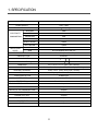
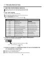
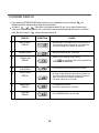
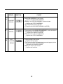
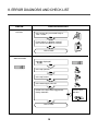
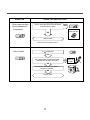
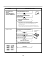
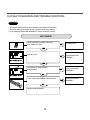
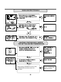
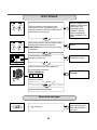
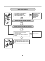
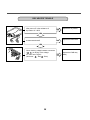
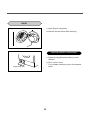
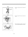
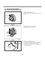
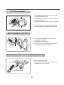
Website:http://www.LGEservice.com [For U.S.A]
www.lg.ca [For CANADA]
E-mail:http://www.LGEservice.com/techsup.html
WASHING MACHINE
SERVICE MANUAL
CAUTION
READ THIS MANUAL CAREFULLY TO DIAGNOSE
TROUBLECORRECTLY BEFORE OFFERING SERVICE.
MODEL : WD-3274RHD / WD-3276RHD
CONTENTS
1. SPECIFICATION............................................................................................................................3
2. FEATURES & TECHNICAL EXPLANATION ................................................................................ 4
3. PARTS IDENTIFICATION ............................................................................................................ 6
4. INSTALLATION ............................................................................................................................. 7
5. OPERATION ................................................................................................................................10
6. WIRING DIAGRAM / PROGRAM CHART ...................................................................................12
7. TROUBLESHOOTING.................................................................................................................13
7-1.BEFORE PERFORMING SERVICE ....................................................................................13
7-2.QC TEST MODE..................................................................................................................13
7-3.HOW TO KNOW THE WATER LEVEL FREQUENCY.........................................................13
7-4.ERROR DISPLAY ................................................................................................................14
8. ERROR DIAGNOSIS AND CHECK LIST ....................................................................................16
8-1. DIAGNOSIS AND ANSWER FOR ABNORMAL OPERATION ...........................................16
8-2. FAULT DIAGNOSIS AND TROUBLESHOOTING ..............................................................19
9. DISASSEMBLY INSTRUCTIONS ...............................................................................................29
10. EXPLODED VIEW AND PARTS LIST .......................................................................................39
10-1. THE EXPLODED VIEW OF CABINET ASSEMBLY .........................................................39
10-2. THE EXPLODED VIEW OF CONTROL PANEL AND DISPENSER ASSEMBLY ............40
10-3. THE EXPLODED VIEW OF DRUM AND TUB ASSEMBLY .............................................41
10-4. THE EXPLODED VIEW OF DRYER ................................................................................42
APPENDIX (Replacement parts list) ...........................................................................................43
2
1. SPECIFICATION
ITEM
WD-3274RHD / WD-3276RHD
POWER SUPPLY
120V~, 60Hz
PRODUCT WEIGHT
156 1/2 lbs. (71 kg)
WASHING
140W
ELECTRICITY
SPIN
300W
CONSUMPTION
FAN MOTOR
25W
DRAIN MOTOR
40W
WASH HEATER
1000W
DRY HEATER
1200W
WASH
45rpm
SPIN
No spin/400/800/1000/1400 rpm
REVOLUTION
SPEED
OPERATION WATER PRESSURE
4.5 ~ 145 PSI (30 ~ 1000 KPa)
CONTROL TYPE
Electronic
WASH CAPACITY
152/5 lbs. 7.0 kg
DRY CAPACITY3.0kg
84/5 lbs. 4.0 kg
DIMENSION
235/8 x 235/8 x 331/2 in. (600 x 600 x 850mm)
WASH PROGRAM
Cotton, Perm. Press, Wool/Silk, Rinse+Spin, Sanitary
WASH/DRY PROGRAM
Cotton, Perm. Press, Rinse+Spin, Sanitary
OPTION
Dry only, Extra Rinse, Extra Wash
DOOR SWITCH TYPE
Bi-Metal type
WATER LEVEL
8 steps (by sensor)
RESERVATION
From 3 hours to 19 hours
SENSING OF THE LAUNDRY AMOUNT
Adapted
FUZZY LOGIC
Adapted
DISPLAY OF THE REMAINING TIME
Adapted
ERROR DIAGNOSIS
10 items
POWER AUTO OFF
Adapted
CHILD LOCK
Adapted
AUTO RESTART
Adapted
RAPID
Adapted
3
2. FEATURES & TECHNICAL EXPLANATION
2-1.FEATURES
Automatic process from washing to drying.
Automatic process from washing to drying can be
selected easily.
Washing capacity : 15 5/2 lbs.¡c7.0 kg¡d
Drying capacity : 8 4/5 lbs.¡c4.0 kg¡d
More economical by Intelligent Wash System
Intelligent Wash System detects the amount of load and
water temperature, and then determines the optimum water
level and washing time to minimize energy and water
consumption.
Direct Drive system
The advanced Brushless DC motor rotates the Drum directly
without belt and pulley.
SPIN
TIME DELAY
Child-Lock
The Child-Lock system has been developed to prevent
children from pressing any button to change the program
during operation.
Low noise speed control system
By sensing the amount of load and balance, automaticaly
distributes load evenly to minimize the spinning noise level.
Auto Restart
Although the washing machine is turned off by a power failure,
it restarts automatically where it stopped when power is
supplied again. And it will be the same if the machine
unplugged and is plugged in again.
4
2-2.DETERMINE WASHING TIME BY FUZZY LOGIC
To get the best washing performance optimal time is determined by sensing of water temperature,
selected washing temperature and laundry amount.
water
temperature
washing time
selected
washing
temperature
FUZZY
LOGIC
rinsing time
the best
washing
performance
spin rhythm, time
laundry
amount
SENSING
PROCESSING
DETERMINATION
EFFECT
2-3.WATER LEVEL CONTROL
This model adopts a pressure sensor which can sense the water level in the tub.
Water supply is stopped when the water level to the preset level, then the washing program proceeds.
Spinning does not proceed until the water in the tub reduces a certain level.
5
3. PARTS IDENTIFICATION
Power plug
If the supply cord is damaged,
it must be replaced by the
manufacturer or its service agents
or a similarly qualified person in
order to avoid a hazard.
Drawer
(For detergent and
fabric softener)
Control panel
Drain hose
Door
Drum
Lower cover
Adjustable feet
Drain pump filter
Lower cover cap
Drain plug
ACCESSORIES
Inlet hose(1 each)
Wrench
6
4. INSTALLATION
Before servicing ask trouble the customer, what the trouble is.
Check the adjustment (power supply is 120V~ remove the transit bolts....)
Check the troubles referring to the troubleshooting.
Decide service steps referring to disassembly instructions.
Then, service and repair.
After servicing, operate the appliance to see whether it works O K or NOT.
STANDARD INSTALLATION
The appliance should be installed as follows.
REMOVE THE TRANSIT
INSTALL THE APPLIANCE
ADJUST THE
BOLTS
ON FLAT AND FIRM SURFACE
HORIZONTAL
Remove the transit bolts
(3EA: ) with supplied spanner.
Turn the leveling feet to
set the appliance horizontally.
Keep the transit bolts and
spanner for future use.
Insert the 3 caps
provided into the hole
1
The appliance goes up by
rotating the feet clockwise.
2
The appliance come down by
rotating the feet counterclockwise.
7
HOW TO CONNECT INLET HOSE
Check that the rubber washer is inside of the
valve connector.
Connect the inlet hose firmly to prevent leak.
CONNECT DRAIN HOSE
Make sure that the hose is not twisted.
Avoid submerging the end of the hose.
The drain hose should be placed under 100cm from the floor.
CONNECT POWER PLUG
Avoid connecting several electric devices,
It may be the cause of a fire.
Connect the power plug to the wall outlet.
8
TEST OPERATION
Preparation for
washing.
Press the power button.
POWER
Connect the power plug to
the outlet.
Connect the inlet hose.
Check the water heating.
Press the button TEMP.
and the present temperature
will be displayed.
Check drain and spin
Turn off Spin and Temp after
pressing the Start/Pause button
and start the machine again.
Check drain and Spin.
Press the Start/Pause
button.
START/PAUSE
In case of Coloureds program.
Check automatic reverse
turn.
Check if the drum rotates
clockwise and
counterclockwise.
Power off and open the
door
Check the water supply.
Check if water is supplied
through the detergent
dispenser.
Water removal
POWER
Power off and then power on.
Check if the door can be
opened after 3 minutes.
9
If SVC is needed during check,
remove the remaining water by
pulling out the hose cap.
5. OPERATION
Option
Rinse hold
Extra Wash
• If the laundry is heavily soiled,
“Extra Wash” course is
effective.
• Extra Wash is available in
Sanitary, Cotton and
Perm. press.
If you desire to leave fabrics in the machine without spinning after rinse to
prevent them wrinkling, you may select rinse hold by pressing the spin
button.
If you want to drain and spin, when Rinse Hold function is proceed, Press
the Start/Pause button to cancel the Rinse Hold function and select spin
speed or program. Press the Start/Pause button again to start program.
If you want to drain only, select the no spin.
If lamp turns on, that function has been selected.
Extra Rinse
• This option can be used to
add a rinse for people with
sensitive skin. Selecting the
Extra Rinse button is also
recommended when washing
heavily soiled fabrics which
needs a lot of detergent, or
when the wash load contains
towelling fabrics that have a
greater tendency to retain
detergent.
WAS
AS
HOT/COLD
WARM/WARM
DRY ONLY
EXTRA RINSE
EXTRA WASH
Water temperature selector
RINS
1000
800
WARM/COLD
OPTION
1400
400
COLD/COLD
NO SPIN
TAB COLD/COLD
RINSE HOLD
TEMP.
SPIN
TIME LEFT
DRY
AUTO DRY
DOO
TIME DRY
STA
AR
TIME DELAY
Child - lock
Press the button to select water temperature.
The water temperature
[WARM/COLD WARM/WARM HOT/COLD
TAB COLD/COLD COLD/COLD] selected in Cotton
or Perm. Press.
[HOT/COLD] is selected for Sanitary only.
By pressing the button while operating the washer,
the present temperature is displayed.
10
SPIN
Child Lock system can be set and canceled by pressing
both [SPIN] and [TIME DELAY ] button simultaneously.
Once Child Lock is set, all button are inoperable.
Child Lock system can be set anytime even during
Power-off and operation.
It is automatically cancelled when an operational error
occur.
DRY
LED display
Wash & Wash/Dry program selector
It displays the remaining time (Hour : Minute ) to
finish.
In case of abnormal operation, error indications are
displayed.
(
9 programs can be set depending on the type of the
laundry.
By turning the program dial, Cotton Perm.Press
Wool/Silk Rinse+Spin ❉Rinse+Spin
❉Perm. Press ❉Cotton ❉Sanitary Sanitary
[❉:Wash/Dry]
(The opposite order is possible)
)
See troubleshooting guide.
Power button
WASH
WASH RINSE+SPIN
RINSE
WOOL/SILK
SPIN
PREM. PRESS
Press the button to turn power
on and off.
Press the button to cancel the
delay finish.
RINSE+SPIN
PREM. PRESS
COTTON
DRY
COTTON
DOOR LOCK
START/PAUSE
DRY
SANITARY
SANITARY
WASH/DRY
START/PAUSE
POWER
Start/Pause button
Use the button to start or
pause wash cycle.
The power turns off
automatically 4 minutes after
the pause button is pressed.
Time Delay
Press the button when delayed washing is needed.
When the button is pressed, [
] is displayed,
maximum delay of [
] hours can be set.
Each press advances time delay by the hour.
Use [POWER]button to cancel [TIME DELAY].
[TIME DELAY] means the time required from the
present to the completion of washing.
Dry Selector
• Dry programs can be selected by ressing the
[DRY] button.
• By pressing the button, [AUTO DRY
TIME DRY(30/60/150)] can be selected.
11
6. WIRING DIAGRAM / PROGRAM CHART
*( ) : Wash/Dry
PRGRAM CHART (KGD2-PJT)
Rinse
Cotton
Perm. Press
22
23
D•T
21
24
25
26 27 20
A
U
T
O
O
F
F
20
(min) 60 240 120 180 60 240 120 180 60 240 120 180 60 240 120 180 60 480 180 ”— 20
20
8
Normal
working
Time
About 1:22(4:31)
8
About 1:17(4:25)
About 1:37(4:46)
Sanitary
Wool/Silk
Rinse+Spin
DRY
20
spin
19
E
N
D
drain
18
W•S
17
rinse
16
drain
15
I•S
14
4
W•S
rinse
13
drain
12
I•S
11
W•S
10
rinse
9
drain
8
3
I•S
7
W•S
6
Spin
Rinse+
2
rinse
5
drain
4
I•S
3
TIME
(sec)120 (min) 60 240 120
washing
W•S
2
1
washing
drain
1
Normal
Main
I•S
W•S
C
O
U
R
S
E
washing
Pre
heating
CYCLE
S
T
E
P
* Water Supply : W•S / Intermittent Spin : I•S / Distangle : D•T
Washing
About 56
8
About 32
Spin
About 12
: Basic Cycle
*
: Optional Cycle
*
* Pre-Setting Time : Water Supply - 120 sec.
Drain
* Basic time is minute in washing chart
* The actual program time can be varied with the load amount.
- 60 sec.
12
7. TROUBLESHOOTING
7-1.BEFORE PERFORMING SERVICE
Be careful of electric shock or disconnecting the parts while trouble shooting.
Voltage of each terminal in 120V~ and DC while applying an electric current.
7-2.QC TEST MODE.
¤ÁPressing SPIN, and TEMP. button simultaneously.
¤ŁPower supply ON with pressing upper two button.Then buzzer sound twice.
¤ØPress the START/PAUSE button as follows.
Press the START/PAUSE button more 4 times until stop spinning
Pressing number of
START/PAUSE button
Checking Point
Display Status
None
All lamps turn on
1 time
Clockwise spin (right)
Drum rpm (About 40~52)
2 times
Low speed Spin
Drum rpm (About 70~90)
3 times
High speed Spin
Drum rpm (About 110~130)
4 times
Inlet valve for pre-wash operation
Water level frequency (25~65)
5 times
Inlet valve for main-wash operation
Water level frequency (25~65)
6 times
Inlet valve for dry operation
Water level frequency (25~65)
7 times
Counterclockwise spin (left)
Drum rpm (About 40~52)
8 times
Heater is in operation for 3 sec.
Water temperature
9 times
Draining pump operation
Water level frequency
10 times
Dry operation for 6 minutes
Auto off operation after 6 minutes
7-3.HOW TO KNOW THE WATER LEVEL FREQUENCY
Press the OPTION and TEMP. button simultaneously.
The digits means water level frequency (10-1
ex) 241 : Water level frequency = 241
=24.1
)
10-1
7-4.HOW TO KNOW TO TEMPERATURE OF EACH THERMISTOR
AT OPERATING CONDITION.
■ Thermistor in tub : Press the [WATER TEMP.] button.
■ Thermistor in dry duct : Press the [DRY] button.
■ Thermistor in condensing duct : Press the [SPIN] and [DRY] button simultaneously.
13
7-5.ERROR DISPLAY.
If you press the START/PAUSE button when an error is displayed. any error except
will
disappear and the machine will change into pause status.
In case of
if the error is not resolved within 20 sec., the in case of other errors,
if the error is not resolved within 4 min., power will be turned off automatically and the error code will
blink. But in the case of
, power will not be turned off.
ERROR
SYMPTOM
CAUSE
1
WATER INLET
ERROR
• Not reached to the water level (2 level) within 4
minutes after water supplied or not reached to
the preset water level within 25 minutes.
2
DRAIN ERROR
• Not fully drained within 5 minutes.
3
OVERFLOW
ERROR
4
• Water is over flowing (over 8 level).
¡ If
is displayed, drain pump operates to
drain water automatically.
SENSOR PRESSURE
S/W ERROR
• The sensor pressure switch is out of order.
DOOR OPEN
ERROR
• In case of operating the reservation function or
the other function with door opened. Close the
door, then the error display is resolved.
• The door switch is out of order.
6
IMBALANCE
ERROR
• The appliance is tilted.
• Laundry is gathered to one side.
7
HEATING
ERROR
5
• The THERMISTOR is out of order.
14
ERROR
8
CURRENT
ERROR
SYMPTOM
CAUSE
• MAIN PWB ASSEMBLY is out of order
Replace the MAIN PWB ASSEMBLY
• Winding in the STATOR ASSEMBLY is short-circuited.
Replace the STATOR ASSEMBLY
•
is dispplayed during a high spin
Replace the LEAD WIRE ASSEMBLY (MOTOR)
9
MOTOR
ERROR
• The connector in the LEAD WIRE ASSEMBLY is not connected to
the connnector of STATOR ASSEMBLY
Reconnect or repair the connector
• The hall sensor is out of order/defective.
Replace the STATOR ASSEMBLY
10
DRY
HEATOR
ERROR
• The Dry Heater is out of order
Replace the Dry Heater
• The Connector of the Dry Heater is not connected properly to the
connector in the Main PWB ASSEMBLY
Reconnect or repair the connector
• The Dry fan motor is out of order
Replace the fan Motor.
15
8. ERROR DIAGNOSIS AND CHECK LIST
SYMPTOM
No Power
GUIDE FOR SERVICE CALL
Is the power plug connected firmly to
120V~ outlet?
YES
Power failure? or Breaker opened?
Is the outlet contralled by a switch?
NO
Visit to check
Water inlet trouble
Is
displayed?
YES
Is the tap opened?
YES
Is the tap frozen?
NO
Is the water supply shut-off?
NO
Is filter in the inlet valve clogged with
foreign material?
NO
Visit to check
16
YES
Clean the filter of
inlet valve
GUIDE FOR SERVICE CALL
SYMPTOM
• Door does not open
• Error displayed on
the program
Did you press the START/PAUSE button
when the door is open?
YES
Close the door
NO
Visit to check
Check if the door switch is O.K.
• Drain Trouble
Is
displayed?
YES
Is the debris filter clogged with foreign
material such as pins, coins, etc?
NO
Is the drain hose frozen with water,
kinked, or crushed?
NO
Visit to check
17
YES
Clean up
the filter.
SYMPTOM
Suds overflow from the
appliance.
(In this condition, wash and
spin do not operate normally)
GUIDE FOR SERVICE CALL
Is low-sudsing detergent for the drum
washing machine used?
YES
Is the proper amount of detergent used
as recommended?
LOW-SUDSING
YES
Recommend to reduce the amount
of detergent.
This appliance has the automatic suds sensing function which
operates under much suds condition for good rinse and
preventing overflow.
When much suds are sensed, the suds removing function such
as drain, water input, pause will operate without rotating the drum.
No effect of softener
Is softener put in the correct compartment of
the drawer?
YES
Is the drawer closed during wash?
YES
Is the softener cap clogged?
YES
Explain how to use softener
Clean the compartment for softener
Visit to check
18
Compartment for
softener
8-2.FAULT DIAGNOSIS AND TROUBLE SHOOTING
CAUTION
1. Be careful of electric shock or disconnecting the parts while trouble shooting.
2. First of all, check the connection of each part terminal with wiring diagram.
3. If you replace the MAIN PWB ASSEMBLY, Put in the connectors correctly.
NO POWER
When measuring the voltage of the outlet,
is the voltage AC 120V?
NO
Check the fuse?
NO
Replace MAIN PWB
ASSEMBLY
YES
Reconnect the PWB
ASSEMBLY
YES
Reconnect the PWB
ASSEMBLY
YES
Is the led (1) on?
(1)
<PWB ASSEMBLY (MAIN)>
YES
(2)
<PWB ASSEMBLY (MAIN)>
Is connector (2) disconnected or
disassembled?
NO
Is wire of the PWB ASSEMBLY disconnected?
NO
Replace PWB ASSEMBLY
19
NO WATER SUPPLY
Is water supply shut-off?
NO
NO
Open the tap.
When you press both RINSE button and SPIN
button simultaneously, is the water level frequency
below 240?
YES
Check the AIR CHAMBER
and the tube clogged
with impurity.
Is the inlet valve filter clogged with impurity?
YES
Clean the filter.
NO
Replace the INLET VALVE
ASSEMBLY.
NO
Replace the MAIN PWB
ASSEMBLY
Is the tap opened?
YES
NO
NO
Is resistance between each terminal of INLET
VALVE ASSEMBLY is 2~8kΩ?
YES
Check the voltage of the inlet valve connector
120V~.
(Refer to 7-2 QC TEST MODE)
DETERGENT DOES NOT FLOW IN
Is water supplied?
NO
Refer to
NO WATER SUPPLY
NO
Check the wiring on the
dispenser.
YES
Are replaceptacles correctly connected to the
terminals of the INLET VALVE ASSEMBLY?
Wiring diagram
SOFTENER
MAIN LIQUID
WASH BLEACH
YES
Put the detergent in the
correct position
Is detergent put in the correct compartment of
the drawer?
NO
LIQUID BLEACH
MAIN WASH
YES
MAX
: Detergent
Is the detergent caked or hardened?
20
YES
Clean the drawer.
SOFTENER DOES NOT FLOW IN
Is water supplied?
YES
MAX
Wiring diagram
Are receptacles correctly connected to the terminals
of the INLET VALVE ASSEMBLY?
NO
Refer to
NO WATER SUPPLY
NO
Check the wiring on the
dispenser.
NO
Put it in the correct
compartment.
YES
Clean the Cap and
Drawer.
YES
Fix the bolt tightly.
YES
Replace the STATOR
ASSEMBLY or ROTOR
ASSEMBLY.
YES
Is softener put in the correct compartment of the
drawer?
YES
Is the softener cap clogged?
ABNORMAL SOUND
Is the motor bolt loosened?
NO
Is there friction noise from the motor?
21
HEATING WITHOUT WATER
OPTION
SPIN
When pressing OPTION and SPIN at the same time
after draining, is the water level frequency 248 ~ 262 or
more?
When pressing SPIN, DRY buttons at the same time
while wash, is the water level frequency between
230 - 243 ?
NO
Replace the
S.PRESSURE SWITCH
ASSEMBLY
YES
Replace the MAIN PWB
ASSEMBLY
YES
Repair the DRAIN HOSE
ASSEMBLY.
YES
Remove foreign material.
YES
Reconnect or repair the
connector
YES
Repair the DRAIN PUMP
ASSEMBLY.
NO
Repair the MAIN PWB
ASSEMBLY.
YES
Checking voltage between two pins as press the
POWER button is the voltage 120V~?
AC 120V
DRAIN MALFUNCTIONING
Is the drain hose twisted or frozen?
NO
Is the impeller of the drain pump clogged?
NO
Is the connector disconnected, disassembled?
NO
Is the coil of the drain pump cut-off?
(resistance of coil is 80~150Ω)
(2)
(1)
NO
When checking voltage between connectors
( , )on spinning, is the voltage 120V~
as the figure?
PWB ASSEMBLY (Main)
22
WASH HEATER TROUBLE
When checking the voltage between
connector during whites washing. is the
voltage 120V?
NO
Replace the MAIN PWB
ASSY
YES
Normal
NO
Replace the
HEATER ASSEMBLY
(1)
YES
AC 120V
YELLOW
RED
After power off,is the resistance of wire
(RED-YELLOW) connectors between
10 ~30 ?
1 2 3
NO
After power off and the heater terminal is
disconnected, is the resistance 10~30 ?
HEATING CONTINUOUSLY ABOVE
THE SETTING WATER TEMPERATURE
TEMP.
When pressing WATER TEMP. during, is the
displayed temperature is over 10ûC higher than the selected temperature?
NO
Check if inlet hose is
connected to a hot
faucet ; otherwise,
replace PWB
ASSEMBLY(Main)
YES
Is the resistance between Thermistor
Comectors 2.5k
~ 180k
?
NO
Replace Thermister
YES
When checking THERMISTOR on the tub is the
THERMISTOR loosened above 2mm from
the rubber?
23
YES
Push the THERMISTOR
tightly to the rubber.
SPIN TROUBLE
OPTION
SPIN
Check on the spinning, is the frequency of the
water level 248 or more. The frequency can be
checked by pressing the OPTION and SPIN buttons
at the same time on the program.
NO
YES
OPTION
SPIN
When pressing OPTION, SPIN and POWER buttons
at the same time after power off, press the
START/PAUSE button 1 times, is the drum spinning
at low speed?
Check the S.PRESSURE SWITCH
ASSEMBLY or HOSE (Pressure).
If the problem is on the
S.PRESSURE SWITCH
ASSEMBLY or the HOSE,
replace the S.PRESSURE
SWITCH ASSEMBLY or the
HOSE.
YES
Normal
YES
Correct the connector.
NO
Is it disconnected, or disassembled?
[Red:3pin (1), NA:4pin (2)]
(2)
NO
(1)
Check the motor connector, Is the resistance of
the terminal same as the figure?
MOTOR TERMINAL (1)
¥L
¥M
NO
¥N
Replace the STATOR
ASSEMBLY
Resistance of terminal:
(1)
¥L~¥M / ¥M~¥N / ¥N~¥L About 5Ω 15Ω
YES
Replace the MAIN PWB ASSEMBLY
Door does not open
Is
YES
Displayed?
24
Check switch Assembly,
Door lock connector and
Main PWB ASSEMBLY
(Blue, 3pin)
[dHE] ERROR DISPLAY
Dry duct
Is the resistance of 2 thermistors on
condensing duct and dry duct
2.5kΩ ~ 180kΩ (at 105°C ~ 0°C)
Condensing
duct
Thermistor
Condensing bellows
NO
YES
Replace the thermistor.
• 6322FR2046A :
Condensing Duct
• 6322FR2046B :
Dry Duct
CHECK FOR DRY HEATER TROUBLE
CHECK FOR DRY FAN MOTOR TROUBLE
Disassemble the cabinet cover and
condensing bellows.
Is there any foreign object in condensing
bellows.
NO
Disassemble the dry fan assy and dry duct
upper, and clean foreign object in duct and
fan.
25
YES
Clean the bellows
DRY HEATER TROUBLE
After power off, is the resistance of
dry heater 10 ~ 40Ω?
NO
Replace the dry heater.
YES
Is thermostat closed?
NO
Replace the thermostat.
YES
When checking voltage between connectors
( 1 , 2 ) on drying, is the voltage
NO
AC 120V as the figure?
(Wire color : 1 - Red, 2 - Blue)
26
Replace the PWB assy
(Main)
DRY FAN MOTOR TROUBLE
(2)
(1)
Is it disconnected, or disassembled?
¡[(1) - Nature , 3pin (2) - Red 6pin¡\
YES
Reconnect or
repair connector.
NO
(1)
(2)
(3)
When checking voltage between connectors
¡[(1)~ (2), (2) ~ (3)¡\ on drying, is the
NO
voltage DC 9~15V as the figure?
¡[Wire color : (1) - White, (2) - Blue
(3) - Black¡\
Replace the
PWB ASSEMBLY(Main)
YES
Check the motor connector, is the resistance
of terminal same as the figure?
Resistance of terminal : 1 - 3 : 2~5Ω
NO
2 - 3 : 2~5Ω
1 2 3
27
Replace the
DRY FAN ASSEMBLY.
LOT OF VAPOR IN DRAWER WHEN DRYING
Isn’t the water supply shut-off?
NO
Is tap opened?
NO
Open the tap.
YES
Isn’t the inlet valve filter clogged with impurity? YES
Clean the filter.
NO
Is resistance of the inlet valve terminal
between 2 to 8 kΩ?
YES
Check if the voltage of each terminal of Inlet
Valve is AC 120V.
(Refer to 7.TEST MODE)
28
NO
Replace the inlet valve.
(5220FR2075C)
NO
Replace PWB assy (Main)
9. DISASSEMBLY INSTRUCTIONS
ƒR Disassemble and repair the parts after pulling out power cord from the outlet.
CONTROL PANEL
PLATE ASSY (TOP)
¥LUnscrew the 2 screws on the top plate.
¥M The PLATE ASSEMBLY (Top) is pulled back
and then upward to arrow direction.
¥NThe cover (Inner) is disassembled.
¥L The PWB ASSEMBLY (Display) connectors
are disconnected.
Hook
¥M Pull out drawer, three screws are unscrewed.
¥N Press two upper hooks and pull the control
panel forward.
¥LThe PWB assembly (Display) is disconnected.
¥M When 1 screws are unscrewed on the PWB
insulator and the PWB assembly (Display) is
disassembled from the PWB insulator.
29
PWB ASSEMBLY (POWER)
¥LThe back cover is removed.
¥MTwo screws are unscrewed.
¥NDisconnect connector from the wiring.
¥OPull the PWB ASSEMBLY (Main) to arrow
direction.
DISPENSER ASSEMBLY
¥LThe PLATE ASSEMBLY (Top) and the cover
(lnner) are disassembled.
¥MPull the drawer to arrow direction.
¥NTwo screws are unscrewed.
DRAWER
¥LThe hose clamps (6EA) and the hose are
disassembled.
¥MThe ventilation bellows are disassembled on
the tub.
DISPENSER ASSEMBLY
30
INLET VALVE
¥LDisconnect the wiring connector.
¥M Remove the valve by two screws of the valve
holder.
2
1
ƒTWhen reconnecting the connector
3
VALVE ¥L(DRY)
YL/BK - BK
VALVE ¥M(LIQUID BLEACH)
GY/WH - BK
VALVE ¥N (NORMAL-WASH)
VALVE (HOT)
WH/BK - BK
BL/RD - BK
COVER LOWER
¥L Remove the lower cover to arrow direction
after one screw is unscrewed.
31
DOOR
¥LOpen the door completely.
¥MRemove the two screws from the hinge.
Removing method of remained water
¥LRotate the Cap(Remaining Hose) to arrow
direction.
¥MPull it out from hose.
¡ First, prepare a bucket to put in the remained
water.
Cap(Remaining Hose)
32
GASKET ASSEMBLY
¥LThe cabinet gasket clamp is released.
¥M Two screws are unscrewed from the cabinet
cover.
¥LOne screw is unscrewed from the lower cover.
¥M The lower cover is disassembled by pulling
out.
¥NThree screws are unscrewed from the cabinet.
Cap
(Remaining Hose)
¥LThe control panel is removed.
¥MScrew is unscrewed from the cabinet cover.
33
¥L Remove tub gasket clamp by loosening the
screw.
Tub Gasket
Clamp
¥L Remove dry gasket clamp by loosening the
screw.
Dry
Gasket
Clamp
¥L When reassembling the gasket, put the drain
hole of the gasket downward, then assemble.
Drain Hole
34
PULLEY, MOTOR, DAMPER
¥LRemove the back cover.
¥M After loosening the bolt, Rotor, pull out the
rotor.
Rotor
Bolt
(PULLEY)
¥LRemove the 6 bolt from the stator.
¥MDisconnect the 2 connectors.
HOW TO ASSEMBLE THE MOTOR
(MOTOR)
¥LRemove the bolts at the Tub.
Bolt
¥M The Hinge (Damper) at the base is pulled off
pressing on the snaps at the sharp end.
Hinge
(Damper)
¥N The hinge at the base is pulled off.
(To arrow direction)
Friction
Damper
(FRICTION DAMPER)
35
PUMP
¥LRemove pump outlet hose.
Pump Outlet Hose
¥MRemove tub pump bellows.
¥NRemove cap (Remaining Hose).
¥ODisconnect the wiring.
Screw
¥PThree screws are unscrewed from the cabinet.
¥QRemove the pump to arrow direction.
Cap
(Remaining Hose)
Tub Pump Bellows
HEATER
¥LLoosen the nut.
¥MRemove washing heater by pulling out.
Washing
Heater
Ring Terminal
Nut
CAUTION
When assembling the washing heater, insert
the heater to heater clip on the bottom of tub.
THERMISTOR
¥LPull it out by holding the thermistor bracket.
ƒT If holding the wire and pulling out it, it may be
broken.
Thermistor
Bracket
Thermistor bulb
36
DOOR HINGE ASSEMBLY
¥LTwo screws are unscrewed on the door and
the door is disassembled.
¥MThe cabinet cover clamp is removed and the
gasket is released.
¥NTwo screws are unscrewed on the door hinge.
¥OThe door hinge is disassembled by pushing
the door hinge arm inside the cabinet cover.
SWITCH ASSEMBLY, DOOR LOCK
¥LThe cabinet cover clamp is removed and
the gasket is released.
¥MTwo screws are unscrewed.
¥NThe door lock S/W is disconnected form the
wiring connector and the strap.
WHEN FOREIGN OBJECT STUCK BETWEEN DRUM AND TUB
¥LRemove washing heater.
¥MRemove the foreign object(wire,coin,etc) by
inserting long bar in the hole.
Hole
Washing Heater
37
DRY DUCT
¥LRemove 5 screws and dry fan assembly.
Dry fan
Assembly
Dry Duct Upper
¥MRemove 6 screws and dry duct upper.
¥LRemove 1 screw and dry heater.
Thermostat
Dry Heater
¥MRemove thermostat.
CONDENSING DUCT
¥LRemove 2 screws from cabinet.
¥LRemove clamp and condensing duct.
Condensing Duct
Clamp
Condensing
Bellows
38
10. EXPLODED VIEW AND PART LIST
10-1.THE PART LIST OF CABINET ASSEMBLY
:Non-service part
:Service part
A110
A150
A120
A102
A101
A104
A141
A103
A131
A100
A130
A430
A140
A440
A485
A-22
A450
A133
A410
A303
A310
A300
A200
A277
HOT(ORANGE)
COLD(BLUE)
A201
A275
A220
A276
39
10-2 THE EXPLODED VIEW OF CONTROL PANEL & DISPENSER ASSEMBLY
:Non-service part
:Service part
F170
F160
F300
F460
F461
F310
F430
F450
F220
F120
F110
F210
F130
40
10-3 THE EXPLODED VIEW OF DRUM & TUB ASSEMBLY
:Non-service part
:Service part
K140
K141
K110 K142 K411 K420
K123
K360
K122
K211
K130
K143
K131
K350
K121
K513
K125
F140
K115
K310
K511
K510
K610
K105
K611
K410
K320
K530
K343
K341
K344
K340
K531
K520
41
K540
10-4 THE EXPLODED VIEW OF DRYER
:Non-service part
:Service part
M120
M110
M100
M121
M210
M101
M220
M312
M310
M311
M230
42
AUG. 2002 PRINTED IN KOREA
P/No.:3828ER3013M