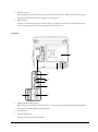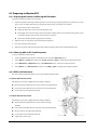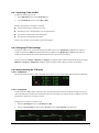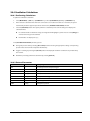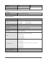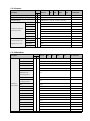
1
Passport 12/Passport 8 Patient Monitor Operator’s Manual © Copyright 2014 Shenzhen Mindray Bio-Medical Electronics Co., Ltd. All rights reserved. Release time: 2014-12 Revision: 1.0 WARNING Federal Law (USA) restricts this device to sale by or on the order of a physician. Intellectual Property Statement SHENZHEN MINDRAY BIO-MEDICAL ELECTRONICS CO., LTD. (hereinafter called Mindray) owns the intellectual property rights to this Mindray product and this manual. This manual may refer to information protected by copyrights or patents and does not convey any license under the patent rights of Mindray, nor the rights of others. Mindray intends to maintain the contents of this manual as confidential information. Disclosure of the information in this manual in any manner whatsoever without the written permission of Mindray is strictly forbidden. Release, amendment, reproduction, distribution, rental, adaption and translation of this manual in any manner whatsoever without the written permission of Mindray is strictly forbidden. , , and are the registered trademarks or trademarks owned by Mindray in China and other countries. All other trademarks that appear in this manual are used only for editorial purposes without the intention of improperly using them. They are the property of their respective owners. Passport 12/Passport 8 Operator’s Manual I Manufacturer’s Responsibility Contents of this manual are subject to changes without prior notice. All information contained in this manual is believed to be correct. Mindray is not liable for errors contained herein nor for incidental or consequential damages in connection with the furnishing, performance, or use of this manual. Mindray is responsible for the effects on safety, reliability and performance of this product, only if: all installation operations, expansions, changes, modifications and repairs of this product are conducted by Mindray authorized personnel; the electrical installation of the relevant room complies with the applicable national and local requirements; the product is used in accordance with the instructions for use. WARNING Only skilled/trained clinical professionals should operate this equipment. It is important for the hospital or organization that uses this equipment to perform a recommended service/maintenance plan. Neglect of this may result in machine breakdown or personal injury. Warranty Mindray warrants that components within its products will be free from defects in workmanship and materials for a period of one year from the date of purchase except that disposable or one-time use products are warranted to be free from defects in workmanship and materials up to a date one year from the date of purchase or the date of first use, whichever is sooner. This warranty does not cover consumable items such as, but not limited to, batteries, external cables, and sensors. Mindray shall not be liable for any incidental, special, or consequential loss, damage, or expense directly or indirectly arising from the use of its products. Liability under this warranty and the buyer’s exclusive remedy under this warranty is limited to servicing or replacing the affected products, at Mindray option, at the factory or at an authorized distributor, for any product which shall under normal use and service appear to Mindray to have been defective in material or workmanship. Recommended preventative maintenance, as prescribed in the service manual, is the responsibility of the user and is not covered by this warranty. No agent, employee, or representative of Mindray has any authority to bind Mindray to any affirmation, representation, or warranty concerning its products, and any affirmation, representation or warranty made by any agent, employee, or representative shall not be enforceable by buyer or user. THIS WARRANTY IS EXPRESSLY IN LIEU OF, AND MINDRAY EXPRESSLY DISCLAIMS, ANY OTHER EXPRESS OR IMPLIED WARRANTIES, INCLUDING ANY IMPLIED WARRANTY OF MERCHANTABILITY, NON-INFRINGEMENT, OR FITNESS FOR A PARTICULAR PURPOSE, AND OF ANY OTHER OBLIGATION ON THE PART OF MINDRAY. II Passport 12/Passport 8 Operator’s Manual Damage to any product or parts through misuse, neglect, accident, or by affixing any non-standard accessory attachments, or by any customer modification voids this warranty. Mindray makes no warranty whatsoever in regard to trade accessories, such being subject to the warranty of their respective manufacturers. A condition of this warranty is that the equipment or accessories which are claimed to be defective be returned when authorized, freight prepaid to Mindray DS USA, Inc., Mahwah, New Jersey 07430 or its authorized representative. Mindray shall not have any responsibility in the event of loss or damage in transit. Exemptions Mindray's obligation or liability under this warranty does not include any transportation or other charges or liability for direct, indirect or consequential damages or delay resulting from the improper use or application of the product or the use of parts or accessories not approved by Mindray or repairs by people other than Mindray authorized personnel. This warranty does not extent to Malfunction or damage caused by improper use or man-made failure. Malfunction or damage caused by unstable or out-of-range power input. Malfunction or damage caused by force majeure events, such as (i) flood, fire and earthquake or other similar elements of nature or acts of God; (ii) riots, war, civil disorders, rebellions, or revolutions in any country; or (iii) any other cause beyond the reasonable control of Mindray. Malfunction or damage caused by improper operation or repair by unqualified or unauthorized service people. Malfunction of the instrument or part whose serial number is not legible. Others not caused by instrument or part itself. Service Mindray maintains a network of service representatives and factory-trained distributors. Prior to requesting service, perform a complete operational check of the instrument to verify proper control settings. If operational problems continue to exist, In North America contact the Service Department at (800) 288-2121, ext: 8116 for Technical Support or (201) 995-8000 for assistance in determining the nearest field service location. Please include the instrument model number, the serial number, and a description of the problem with all requests for service. Any questions regarding the warranty should be directed to your local sales or service representative. NOTE Upon request, Mindray provides circuit diagrams, component part lists, descriptions, calibration instructions, or other information which assist the user’s appropriately qualified technical personnel to repair those parts of the equipment which are designated by Mindray DS USA, Inc. as repairable. Passport 12/Passport 8 Operator’s Manual III Company Contact Manufacturer: Shenzhen Mindray Bio-Medical Electronics Co., Ltd. Address: Mindray Building, Keji 12th Road South, Hi-tech industrial park, Nanshan, Shenzhen 518057,P.R.China IV Website: www.mindray.com E-mail Address: [email protected] Tel: +86 755 81888998 Fax: +86 755 26582680 Distributor: Mindray DS USA, Inc. Address: 800 MacArthur Boulevard, Mahwah, New Jersey, 07430 USA Tel: 1.800.288.2121, 1.201.995.8000 Website: www.mindray.com Passport 12/Passport 8 Operator’s Manual Preface Manual Purpose This manual contains the instructions necessary to operate the product safely and in accordance with its function and intended use. Observance of this manual is a prerequisite for proper product performance and correct operation and ensures patient and operator safety. This manual is based on the maximum configuration and therefore some contents may not apply to your product. If you have any questions, please contact Mindray. This manual is an integral part of the product. It should always be kept close to the equipment so that it can be conveniently referenced when needed. Intended Audience This manual is intended for clinical professionals who are expected to have a working knowledge of medical procedures, practices and terminology as required for monitoring of patients. Illustrations All illustrations in this manual serve as examples only. They may not necessarily reflect the setup or data displayed on your monitor. Manual Conventions Italic text is used to quote the referenced chapters or sections. [ ] is used to enclose screen text. → is used to indicate operational procedures. Passport 12/Passport 8 Operator’s Manual V FOR YOUR NOTES VI Passport 12/Passport 8 Operator’s Manual Contents 1 Safety ................................................................................................................................................................................. 1-1 1.1 Safety Information .......................................................................................................................................................................................... 1-1 1.1.1 Warnings .............................................................................................................................................................................................. 1-1 1.1.2 Cautions ............................................................................................................................................................................................... 1-2 1.1.3 Notes ..................................................................................................................................................................................................... 1-2 1.2 Equipment Symbols....................................................................................................................................................................................... 1-3 2 The Basics ........................................................................................................................................................................... 2-1 2.1 Intended Use .................................................................................................................................................................................................... 2-1 2.2 Applied Parts .................................................................................................................................................................................................... 2-1 2.3 Main Unit ........................................................................................................................................................................................................... 2-2 2.3.1 Front View ............................................................................................................................................................................................ 2-2 2.3.2 Side View .............................................................................................................................................................................................. 2-4 2.3.3 Rear View.............................................................................................................................................................................................. 2-6 2.4 Modules.............................................................................................................................................................................................................. 2-8 2.5 Display Screen .................................................................................................................................................................................................. 2-9 2.6 QuickKeys ........................................................................................................................................................................................................2-11 3 Basic Operations................................................................................................................................................................ 3-1 3.1 Installation ......................................................................................................................................................................................................... 3-1 3.1.1 Unpacking and Checking .............................................................................................................................................................. 3-1 3.1.2 Environmental Requirements ...................................................................................................................................................... 3-2 3.2 Getting Started ................................................................................................................................................................................................ 3-2 3.2.1 Connecting to Power Source ........................................................................................................................................................ 3-2 3.2.2 Turning Power On ............................................................................................................................................................................. 3-3 3.2.3 Starting Monitoring ......................................................................................................................................................................... 3-3 3.3 Turning Off the Monitor ............................................................................................................................................................................... 3-4 3.4 Using the Knob ................................................................................................................................................................................................ 3-4 3.5 Using Keys ......................................................................................................................................................................................................... 3-4 3.6 Using the Touchscreen.................................................................................................................................................................................. 3-5 3.7 Using the On-screen Keyboard .................................................................................................................................................................. 3-5 3.8 Using the Main Menu .................................................................................................................................................................................... 3-5 3.9 Setting the Screen .......................................................................................................................................................................................... 3-6 3.10 Displaying the Timer ................................................................................................................................................................................... 3-7 3.11 Changing General Settings ....................................................................................................................................................................... 3-7 3.11.1 Setting up a Monitor ..................................................................................................................................................................... 3-7 3.11.2 Changing Language ...................................................................................................................................................................... 3-7 3.11.3 Adjusting the Screen Brightness ............................................................................................................................................... 3-8 3.11.4 Showing/Hiding Help Text .......................................................................................................................................................... 3-8 3.11.5 Setting the Date and Time........................................................................................................................................................... 3-8 3.11.6 Adjusting Volume ........................................................................................................................................................................... 3-8 3.12 Setting Parameters ...................................................................................................................................................................................... 3-9 3.12.1 Switching the Parameters On/Off ............................................................................................................................................ 3-9 Passport 12/Passport 8 Operator’s Manual 1 3.12.2 Accessing the Parameters Menu .............................................................................................................................................. 3-9 3.13 Operating Modes ......................................................................................................................................................................................... 3-9 3.13.1 Monitoring Mode .........................................................................................................................................................................3-10 3.13.2 Night Mode ....................................................................................................................................................................................3-10 3.13.3 Privacy Mode .................................................................................................................................................................................3-10 3.13.4 Demo Mode ................................................................................................................................................................................... 3-11 3.13.5 Standby Mode ............................................................................................................................................................................... 3-11 4 Managing Patients ............................................................................................................................................................ 4-1 4.1 Admitting a Patient ........................................................................................................................................................................................ 4-1 4.2 Quick Admitting a Patient ........................................................................................................................................................................... 4-1 4.3 Querying and Obtaining Patient Information ..................................................................................................................................... 4-2 4.4 Associating Patient Information ................................................................................................................................................................ 4-2 4.5 Editing Patient Information ........................................................................................................................................................................ 4-2 4.6 Discharging a Patient .................................................................................................................................................................................... 4-3 4.7 Transferring Patient Data ............................................................................................................................................................................. 4-3 4.7.1 Transferring Data from the Monitor to a USB Drive ............................................................................................................. 4-3 4.7.2 Transferring Data from a USB Drive to the Monitor ............................................................................................................. 4-4 4.8 Connecting to a CMS .................................................................................................................................................................................... 4-4 5 Managing Configurations ................................................................................................................................................. 5-1 5.1 Introduction ..................................................................................................................................................................................................... 5-1 5.2 Entering the [Manage Configuration] Menu ........................................................................................................................................ 5-2 5.3 Changing Department ................................................................................................................................................................................. 5-2 5.4 Setting Default Configuration ................................................................................................................................................................... 5-3 5.5 Saving Current Settings ............................................................................................................................................................................... 5-3 5.6 Editing Configurations.................................................................................................................................................................................. 5-4 5.7 Deleting a Configuration ............................................................................................................................................................................. 5-5 5.8 Transferring a Configuration ...................................................................................................................................................................... 5-5 5.9 Loading a Configuration .............................................................................................................................................................................. 5-6 5.10 Restoring the Latest Configuration Automatically .......................................................................................................................... 5-6 5.11 Modifying Password .................................................................................................................................................................................... 5-6 6 User Screens ....................................................................................................................................................................... 6-1 6.1 Configuring Your Screens ............................................................................................................................................................................ 6-1 6.1.1 Changing the Waveform Line Size ............................................................................................................................................. 6-1 6.1.2 Changing Measurement Colors .................................................................................................................................................. 6-1 6.1.3 Changing Screen Layout ................................................................................................................................................................ 6-1 6.2 Viewing Minitrends ........................................................................................................................................................................................ 6-2 6.2.1 Having a Split-Screen View of Minitrends ............................................................................................................................... 6-2 6.2.2 Setting Minitrends ........................................................................................................................................................................... 6-2 6.3 Viewing OxyCRG ............................................................................................................................................................................................. 6-3 6.4 Viewing Other Patients ................................................................................................................................................................................. 6-4 6.4.1 Care Group .......................................................................................................................................................................................... 6-4 6.4.2 Viewing the Care Group Overview Bar ..................................................................................................................................... 6-4 6.4.3 Understanding the View Other Patient Window................................................................................................................... 6-5 2 Passport 12/Passport 8 Operator’s Manual 6.5 Understanding the Big Numerics Screen ............................................................................................................................................... 6-6 7 Alarms ................................................................................................................................................................................ 7-1 7.1 Alarm Categories ............................................................................................................................................................................................. 7-1 7.2 Alarm Levels ...................................................................................................................................................................................................... 7-2 7.3 Alarm Indicators .............................................................................................................................................................................................. 7-2 7.3.1 Alarm Lamp ......................................................................................................................................................................................... 7-2 7.3.2 Alarm Messages ................................................................................................................................................................................. 7-2 7.3.3 Flashing Numeric .............................................................................................................................................................................. 7-3 7.3.4 Audible Alarm Tones ........................................................................................................................................................................ 7-3 7.3.5 Alarm Status Symbols ...................................................................................................................................................................... 7-3 7.4 Alarm Tone Configuration ............................................................................................................................................................................ 7-4 7.4.1 Setting the Minimum Alarm Volume ......................................................................................................................................... 7-4 7.4.2 Changing the Alarm Volume......................................................................................................................................................... 7-4 7.4.3 Setting the Interval Between Alarm Sounds ........................................................................................................................... 7-4 7.4.4 Changing the Alarm Tone Pattern............................................................................................................................................... 7-5 7.4.5 Setting the Reminder Tones.......................................................................................................................................................... 7-5 7.5 Understanding the Alarm Setup Menu................................................................................................................................................... 7-6 7.5.1 Setting Alarm Properties for All Parameters ............................................................................................................................ 7-6 7.5.2 Adjusting Alarm Limits Automatically ....................................................................................................................................... 7-7 7.5.3 Setting Alarm Delay Time............................................................................................................................................................... 7-9 7.5.4 Setting SpO2 Technical Alarm Delay .........................................................................................................................................7-10 7.5.5 Setting Recording Length............................................................................................................................................................7-10 7.5.6 Entering CPB Mode (Cardiopulmonary Bypass Mode) .....................................................................................................7-10 7.6 Pausing Alarms...............................................................................................................................................................................................7-10 7.7 Switching Off All Alarms .............................................................................................................................................................................7-11 7.8 Resetting Alarms ...........................................................................................................................................................................................7-11 7.9 Latching Alarms .............................................................................................................................................................................................7-12 7.10 Testing Alarms..............................................................................................................................................................................................7-12 7.11 Using Care Group Alarms .........................................................................................................................................................................7-13 7.11.1 Care Group Auto Alarms .............................................................................................................................................................7-13 7.11.2 Setting Care Group Alert Tone .................................................................................................................................................7-13 7.11.3 Resetting Care Group Alarms ...................................................................................................................................................7-13 8 Monitoring ECG ................................................................................................................................................................. 8-1 8.1 Introduction ...................................................................................................................................................................................................... 8-1 8.2 Safety ...................................................................................................................................................................................................................8-1 8.3 Preparing to Monitor ECG ............................................................................................................................................................................ 8-2 8.3.1 Preparing the Patient and Placing the Electrodes ................................................................................................................ 8-2 8.3.2 Choosing AHA or IEC Lead Placement ....................................................................................................................................... 8-2 8.3.3 ECG Lead Placements ...................................................................................................................................................................... 8-2 8.3.4 Checking Paced Status.................................................................................................................................................................... 8-3 8.4 Understanding the ECG Display ................................................................................................................................................................ 8-4 8.5 Changing ECG Settings................................................................................................................................................................................. 8-5 8.5.1 Accessing ECG Menus...................................................................................................................................................................... 8-5 8.5.2 Setting Pacemaker Rate (For Mortara ECG algorithm only) .............................................................................................. 8-5 Passport 12/Passport 8 Operator’s Manual 3 8.5.3 Choosing the Alarm Source .......................................................................................................................................................... 8-5 8.5.4 Changing ECG Wave Settings....................................................................................................................................................... 8-5 8.5.5 Changing the ECG Filter Settings ............................................................................................................................................... 8-6 8.5.6 Setting Pacemaker Rate (For Mortara only) ............................................................................................................................ 8-6 8.5.7 Setting the ECG Lead Set ............................................................................................................................................................... 8-6 8.5.8 Choosing an ECG Display Screen ................................................................................................................................................ 8-6 8.5.9 Setting the Notch Filter .................................................................................................................................................................. 8-7 8.5.10 Changing the Pacer Reject Settings ........................................................................................................................................ 8-7 8.5.11 Enabling Smart Lead Off .............................................................................................................................................................. 8-7 8.5.12 Setting the Alarm Level for ECG Lead Off Alarms ............................................................................................................... 8-7 8.5.13 Adjusting QRS Volume ................................................................................................................................................................. 8-8 8.5.14 About the Defibrillator Synchronization ............................................................................................................................... 8-8 8.6 About ST Monitoring ..................................................................................................................................................................................... 8-8 8.6.1 Switching ST On and Off ................................................................................................................................................................ 8-9 8.6.2 Changing ST Filter Settings ........................................................................................................................................................... 8-9 8.6.3 Understanding the ST Display ..................................................................................................................................................... 8-9 8.6.4 Saving the Current ST Segment as Reference ...................................................................................................................... 8-10 8.6.5 Changing the Reference Segment ...........................................................................................................................................8-10 8.6.6 Deleting a Reference Segment ..................................................................................................................................................8-10 8.6.7 Recording the ST Segment .........................................................................................................................................................8-10 8.6.8 Changing the ST Alarm Limits ....................................................................................................................................................8-10 8.6.9 Setting the ST Alarm Delay Time ............................................................................................................................................... 8-11 8.6.10 Adjusting ST Measurement Points ......................................................................................................................................... 8-11 8.7 About Arrhythmia Monitoring .................................................................................................................................................................8-12 8.7.1 Understanding the Arrhythmia Events ................................................................................................................................... 8-12 8.7.2 Changing Arrhythmia Alarm Settings .....................................................................................................................................8-14 8.7.3 Changing Arrhythmia Threshold Settings ............................................................................................................................. 8-14 8.7.4 Setting the Extended Arrhythmia (For Mindray ECG Algorithm only, currently unavailable in the US and Canada) .........................................................................................................................................................................................................8-15 8.7.5 Reviewing Arrhythmia Events ....................................................................................................................................................8-15 8.8 ECG Relearning ..............................................................................................................................................................................................8-16 8.8.1 Initiating an ECG Relearning Manually ................................................................................................................................... 8-16 8.8.2 Automatic ECG Relearning ..........................................................................................................................................................8-16 8.9 Troubleshooting............................................................................................................................................................................................8-16 9 Monitoring Respiration (Resp) ......................................................................................................................................... 9-1 9.1 Introduction ..................................................................................................................................................................................................... 9-1 9.2 Safety Information ......................................................................................................................................................................................... 9-1 9.3 Understanding the Resp Display .............................................................................................................................................................. 9-1 9.4 Placing Resp Electrodes ............................................................................................................................................................................... 9-2 9.4.1 Optimizing Lead Placement for Resp ........................................................................................................................................ 9-2 9.4.2 Cardiac Overlay ................................................................................................................................................................................. 9-2 9.4.3 Abdominal Breathing ...................................................................................................................................................................... 9-2 9.4.4 Lateral Chest Expansion ................................................................................................................................................................. 9-3 9.5 Choosing the Respiration Lead ................................................................................................................................................................. 9-3 9.6 Changing the Apnea Alarm Delay ............................................................................................................................................................ 9-3 4 Passport 12/Passport 8 Operator’s Manual 9.7 Changing Resp Detection Mode ............................................................................................................................................................... 9-3 9.8 Changing Resp Wave Settings ................................................................................................................................................................... 9-4 9.9 Setting Respiration Rate Source ................................................................................................................................................................ 9-4 9.10 Setting Alarm Properties............................................................................................................................................................................ 9-4 10 Monitoring PR ............................................................................................................................................................... 10-1 10.1 Introduction .................................................................................................................................................................................................10-1 10.2 Setting the PR Source ...............................................................................................................................................................................10-1 10.3 Selecting the Active Alarm Source .......................................................................................................................................................10-2 10.4 QRS Tone........................................................................................................................................................................................................10-2 11 Monitoring SpO2 ............................................................................................................................................................ 11-1 11.1 Introduction..................................................................................................................................................................................................11-1 11.2 Safety...............................................................................................................................................................................................................11-2 11.3 Identifying SpO2 Modules........................................................................................................................................................................11-2 11.4 Applying the Sensor ..................................................................................................................................................................................11-2 11.5 Changing SpO2 Settings ...........................................................................................................................................................................11-3 11.5.1 Accessing SpO2 Menus ................................................................................................................................................................11-3 11.5.2 Adjusting the Desat Alarm .........................................................................................................................................................11-3 11.5.3 Setting SpO2 Sensitivity ..............................................................................................................................................................11-3 11.5.4 Changing Averaging Time .........................................................................................................................................................11-3 11.5.5 Monitoring SpO2 and NIBP Simultaneously ........................................................................................................................ 11-3 11.5.6 Sat-Seconds Alarm Management ...........................................................................................................................................11-4 11.5.7 Changing the Speed of the Pleth Wave ................................................................................................................................ 11-5 11.5.8 Zooming PI Value ..........................................................................................................................................................................11-5 11.5.9 Setting the Alarm Level for SpO2 Sensor Off Alarm .......................................................................................................... 11-5 11.5.10 Setting the SpO2 Tone Mode ..................................................................................................................................................11-5 11.6 Measurement Limitations........................................................................................................................................................................11-6 11.7 Masimo Information ..................................................................................................................................................................................11-6 11.8 Nellcor Information ....................................................................................................................................................................................11-7 11.9 Troubleshooting ..........................................................................................................................................................................................11-7 12 Monitoring NIBP ............................................................................................................................................................ 12-1 12.1 Introduction .................................................................................................................................................................................................12-1 12.2 Safety ..............................................................................................................................................................................................................12-2 12.3 Measurement Limitations .......................................................................................................................................................................12-2 12.4 Measurement Methods ............................................................................................................................................................................12-2 12.5 Setting Up the NIBP Measurement ......................................................................................................................................................12-3 12.5.1 Preparing the Patient ..................................................................................................................................................................12-3 12.5.2 Preparing to Measure NIBP .......................................................................................................................................................12-3 12.5.3 Starting and Stopping Measurements .................................................................................................................................12-4 12.5.4 Correcting the Measurement if Limb is not at Heart Level ...........................................................................................12-4 12.5.5 Enabling NIBP Auto Cycling and Setting the Interval......................................................................................................12-4 12.5.6 Starting a STAT Measurement ..................................................................................................................................................12-4 12.6 Understanding the NIBP Numerics ......................................................................................................................................................12-5 12.7 Changing NIBP Settings ...........................................................................................................................................................................12-5 Passport 12/Passport 8 Operator’s Manual 5 12.7.1 Setting the Initial Cuff Inflation Pressure ............................................................................................................................. 12-5 12.7.2 Setting NIBP Alarm Properties .................................................................................................................................................12-5 12.7.3 Displaying NIBP List.....................................................................................................................................................................12-6 12.7.4 Setting the Pressure Unit ..........................................................................................................................................................12-6 12.7.5 Switching On NIBP End Tone ...................................................................................................................................................12-6 12.8 Assisting Venous Puncture......................................................................................................................................................................12-6 13 Monitoring Temp ........................................................................................................................................................... 13-1 13.1 Introduction .................................................................................................................................................................................................13-1 13.2 Safety ..............................................................................................................................................................................................................13-1 13.3 Making a Temp Measurement ...............................................................................................................................................................13-1 13.4 Understanding the Temp Display ........................................................................................................................................................13-1 13.5 Setting the Temperature Unit ................................................................................................................................................................13-2 14 Monitoring IBP .............................................................................................................................................................. 14-1 14.1 Introduction .................................................................................................................................................................................................14-1 14.2 Safety ..............................................................................................................................................................................................................14-1 14.3 Zeroing the Transducer ............................................................................................................................................................................14-1 14.4 Setting Up the Pressure Measurement ..............................................................................................................................................14-2 14.5 Understanding the IBP Display .............................................................................................................................................................14-3 14.6 Changing IBP Settings ..............................................................................................................................................................................14-4 14.6.1 Changing a Pressure for Monitoring .....................................................................................................................................14-4 14.6.2 Setting Alarm Properties ...........................................................................................................................................................14-4 14.6.3 Changing Averaging Time ........................................................................................................................................................14-5 14.6.4 Setting Up the IBP Wave ............................................................................................................................................................14-5 14.6.5 Setting the Pressure Unit ..........................................................................................................................................................14-5 14.6.6 Enabling PPV Measurement and Setting PPV Source..................................................................................................... 14-5 14.7 Overlapping IBP Waveforms ..................................................................................................................................................................14-6 14.8 Measuring PAWP ........................................................................................................................................................................................14-7 14.8.1 Preparing to Measure PAWP..................................................................................................................................................... 14-7 14.8.2 Setting Up the PAWP Measurement ......................................................................................................................................14-8 14.8.3 Understanding the PAWP Setup Menu ................................................................................................................................ 14-8 14.9 Troubleshooting .........................................................................................................................................................................................14-9 15 Monitoring Cardiac Output .......................................................................................................................................... 15-1 15.1 Introduction .................................................................................................................................................................................................15-1 15.2 Understanding the C.O. Display ...........................................................................................................................................................15-1 15.3 Influencing Factors ....................................................................................................................................................................................15-2 15.4 Setting Up the C.O. Measurement .......................................................................................................................................................15-3 15.5 Measuring the Blood Temperature ......................................................................................................................................................15-6 15.6 Changing C.O. Settings ............................................................................................................................................................................15-6 15.6.1 Setting the Temperature Unit ..................................................................................................................................................15-6 15.6.2 Setting Alarm Properties ...........................................................................................................................................................15-6 16 Monitoring CO2 .............................................................................................................................................................. 16-1 16.1 Introduction .................................................................................................................................................................................................16-1 6 Passport 12/Passport 8 Operator’s Manual 16.2 CO2 Module...................................................................................................................................................................................................16-2 16.3 Preparing to Measure CO2 .......................................................................................................................................................................16-2 16.3.1 Making a Sidestream CO2 Measurement .............................................................................................................................16-3 16.3.2 Making a Microstream CO2 Measurement ..........................................................................................................................16-4 16.4 Changing CO2 Settings .............................................................................................................................................................................16-4 16.4.1 Accessing CO2 Menus ..................................................................................................................................................................16-4 16.4.2 Entering the Standby Mode .....................................................................................................................................................16-4 16.4.3 Setting the CO2 Unit ....................................................................................................................................................................16-5 16.4.4 Setting up Gas Compensations ...............................................................................................................................................16-5 16.4.5 Setting up Humidity Compensation .....................................................................................................................................16-5 16.4.6 Setting the Apnea Alarm Delay ...............................................................................................................................................16-6 16.4.7 Choosing a Time Interval for Peak-Picking ..........................................................................................................................16-6 16.4.8 Setting the Flow Rate ..................................................................................................................................................................16-6 16.4.9 Setting up the CO2 Wave............................................................................................................................................................16-7 16.5 Setting RR Source .......................................................................................................................................................................................16-7 16.6 Barometric Pressure Compensation ....................................................................................................................................................16-7 16.7 Measurement Limitations .......................................................................................................................................................................16-8 16.8 Leakage test .................................................................................................................................................................................................16-8 16.9 Troubleshooting the Sidestream CO2 Sampling System ..............................................................................................................16-8 16.10 Removing Exhaust Gases from the System ....................................................................................................................................16-9 16.11 Zeroing the Sensor ..................................................................................................................................................................................16-9 16.12 Calibrating the Sensor......................................................................................................................................................................... 16-10 16.13 Oridion Information ............................................................................................................................................................................. 16-10 17 Monitoring AG ............................................................................................................................................................... 17-1 17.1 Introduction .................................................................................................................................................................................................17-1 17.2 Understanding the AG Display ..............................................................................................................................................................17-2 17.3 MAC Values ...................................................................................................................................................................................................17-2 17.4 Preparing to Measure AG .........................................................................................................................................................................17-4 17.5 Changing AG Settings...............................................................................................................................................................................17-5 17.5.1 Setting Gas Unit ............................................................................................................................................................................17-5 17.5.2 Setting the Apnea Alarm Delay ...............................................................................................................................................17-5 17.5.3 Changing the Sample Flow Rate ............................................................................................................................................17-5 17.5.4 Setting up the O2 Compensation ...........................................................................................................................................17-5 17.5.5 Entering the Standby Mode .....................................................................................................................................................17-6 17.5.6 Setting up the AG Wave .............................................................................................................................................................17-6 17.5.7 Setting RR Source .........................................................................................................................................................................17-6 17.6 Changing the Anesthetic Agent ............................................................................................................................................................17-6 17.7 Measurement Limitations .......................................................................................................................................................................17-7 17.8 Troubleshooting .........................................................................................................................................................................................17-7 17.8.1 When the Gas Inlet is Blocked..................................................................................................................................................17-7 17.8.2 When an Internal Occlusion Occurs.......................................................................................................................................17-7 17.8.3 When an Internal Occlusion Occurs.......................................................................................................................................17-7 17.9 Removing Exhaust Gases from the System ......................................................................................................................................17-8 18 Freezing Waveforms...................................................................................................................................................... 18-1 Passport 12/Passport 8 Operator’s Manual 7 18.1 Freezing Waveforms ..................................................................................................................................................................................18-1 18.2 Viewing Frozen Waveforms ....................................................................................................................................................................18-1 18.3 Unfreezing Waveforms .............................................................................................................................................................................18-2 18.4 Recording Frozen Waveforms ................................................................................................................................................................18-2 19 Review ............................................................................................................................................................................ 19-1 19.1 Accessing Respective Review Windows .............................................................................................................................................19-1 19.2 Reviewing Graphic Trends ......................................................................................................................................................................19-1 19.3 Reviewing Tabular Trends .......................................................................................................................................................................19-2 19.4 Reviewing Events .......................................................................................................................................................................................19-3 19.4.1 Marking Events .............................................................................................................................................................................19-3 19.4.2 Reviewing Events .........................................................................................................................................................................19-4 19.5 Reviewing Waveforms ..............................................................................................................................................................................19-6 20 Calculations ................................................................................................................................................................... 20-1 20.1 Introduction .................................................................................................................................................................................................20-1 20.2 Dose Calculations ......................................................................................................................................................................................20-2 20.2.1 Performing Calculations ............................................................................................................................................................20-2 20.2.2 Selecting the Proper Drug Unit...............................................................................................................................................20-2 20.2.3 Titration Table ................................................................................................................................................................................20-3 20.2.4 Drug Calculation Formulas .......................................................................................................................................................20-3 20.3 Oxygenation Calculations .......................................................................................................................................................................20-3 20.3.1 Performing Calculations ............................................................................................................................................................20-3 20.3.2 Entered Parameters .....................................................................................................................................................................20-4 20.3.3 Calculated Parameters and Formulas ................................................................................................................................... 20-4 20.4 Ventilation Calculations ...........................................................................................................................................................................20-5 20.4.1 Performing Calculations ............................................................................................................................................................20-5 20.4.2 Entered Parameters .....................................................................................................................................................................20-5 20.4.3 Calculated Parameters and Formulas ................................................................................................................................... 20-6 20.5 Hemodynamic Calculations ...................................................................................................................................................................20-6 20.5.1 Performing Calculations ............................................................................................................................................................20-6 20.5.2 Entered Parameters .....................................................................................................................................................................20-7 20.5.3 Calculated Parameters and Formulas ................................................................................................................................... 20-7 20.6 Renal Calculations......................................................................................................................................................................................20-8 20.6.1 Performing Calculations ............................................................................................................................................................20-8 20.6.2 Entered Parameters .....................................................................................................................................................................20-8 20.6.3 Calculated Parameters and Formulas ................................................................................................................................... 20-9 20.7 Understanding the Review Window ...................................................................................................................................................20-9 21 Recording ....................................................................................................................................................................... 21-1 21.1 Using a Recorder ........................................................................................................................................................................................21-1 21.2 Overview of Recording Types ................................................................................................................................................................21-1 21.3 Starting and Stopping Recordings ......................................................................................................................................................21-2 21.4 Setting up the Recorder ..........................................................................................................................................................................21-2 21.4.1 Accessing the Record Setup Menu ........................................................................................................................................21-2 21.4.2 Selecting Waveforms for Recording ......................................................................................................................................21-2 8 Passport 12/Passport 8 Operator’s Manual 21.4.3 Setting the Realtime Recording Length...............................................................................................................................21-3 21.4.4 Setting the Interval between Timed Recordings ..............................................................................................................21-3 21.4.5 Changing the Recording Speed ..............................................................................................................................................21-3 21.4.6 Clearing Recording Tasks ...........................................................................................................................................................21-3 21.5 Loading Paper..............................................................................................................................................................................................21-3 21.6 Removing Paper Jam ................................................................................................................................................................................21-4 21.7 Cleaning the Recorder Printhead .........................................................................................................................................................21-4 22 Printing .......................................................................................................................................................................... 22-1 22.1 Printer .............................................................................................................................................................................................................22-1 22.2 Connecting a printer .................................................................................................................................................................................22-1 22.3 Setting Up the Printer ...............................................................................................................................................................................22-2 22.4 Starting Report Printouts ........................................................................................................................................................................22-2 22.5 Stopping Report Printouts ......................................................................................................................................................................22-3 22.6 Setting Up Reports ....................................................................................................................................................................................22-3 22.6.1 Setting Up ECG Reports .............................................................................................................................................................22-3 22.6.2 Setting Up Tabular Trends Reports ........................................................................................................................................22-3 22.6.3 Setting Up Graphic Trends Reports .......................................................................................................................................22-4 22.6.4 Setting Up Realtime Reports ....................................................................................................................................................22-4 22.7 End Case Reports ........................................................................................................................................................................................22-4 22.8 Printer Statuses ...........................................................................................................................................................................................22-4 22.8.1 Printer Out of Paper .....................................................................................................................................................................22-4 22.8.2 Printer Status Messages .............................................................................................................................................................22-4 23 Other Functions............................................................................................................................................................. 23-1 23.1 Analog Output .............................................................................................................................................................................................23-1 23.2 Exporting the Log ......................................................................................................................................................................................23-1 23.3 Transferring Data ........................................................................................................................................................................................23-1 23.3.1 Data Export System .....................................................................................................................................................................23-1 23.3.2 Transferring Data by Different Means ...................................................................................................................................23-2 23.4 Nurse Call ......................................................................................................................................................................................................23-2 23.5 Network Connection .................................................................................................................................................................................23-3 23.5.1 Setting the Network Type..........................................................................................................................................................23-3 23.5.2 Setting up the Wireless Network ............................................................................................................................................23-4 23.6 Setting the CMS ..........................................................................................................................................................................................23-4 23.6.1 Selecting a CMS ............................................................................................................................................................................23-5 23.6.2 Clearing the Selected CMS at Startup...................................................................................................................................23-5 23.7 Setting the Multicast Parameters .........................................................................................................................................................23-5 24 Batteries ......................................................................................................................................................................... 24-1 24.1 Overview .......................................................................................................................................................................................................24-1 24.2 Charging a Battery .....................................................................................................................................................................................24-1 24.3 Replacing a Battery ....................................................................................................................................................................................24-2 24.4 Battery Guidelines ......................................................................................................................................................................................24-2 24.5 Battery Maintenance .................................................................................................................................................................................24-3 24.6 Battery Recycling ........................................................................................................................................................................................24-4 Passport 12/Passport 8 Operator’s Manual 9 25 Care and Cleaning ......................................................................................................................................................... 25-1 25.1 General Points .............................................................................................................................................................................................25-1 25.2 Cleaning ........................................................................................................................................................................................................25-2 25.3 Disinfecting ..................................................................................................................................................................................................25-2 25.4 Sterilization ..................................................................................................................................................................................................25-2 26 User Maintenance ......................................................................................................................................................... 26-1 26.1 General Inspection ....................................................................................................................................................................................26-1 26.2 Maintenance and Testing Schedule ....................................................................................................................................................26-2 26.3 Checking Monitor and Module Information ....................................................................................................................................26-3 26.4 ECG Verification ..........................................................................................................................................................................................26-3 26.5 NIBP Leakage Test ......................................................................................................................................................................................26-3 26.6 CO2 Leakage Test ........................................................................................................................................................................................26-4 26.7 AG Tests ..........................................................................................................................................................................................................26-5 26.7.1 AG Leakage Test ............................................................................................................................................................................26-5 26.8 Calibrating the Touchscreen ..................................................................................................................................................................26-5 26.9 Entering/Exiting Demo Mode ...............................................................................................................................................................26-5 27 Accessories ..................................................................................................................................................................... 27-1 27.1 ECG Accessories ..........................................................................................................................................................................................27-1 27.2 SpO2 Accessories ........................................................................................................................................................................................27-2 27.3 NIBP Accessories .........................................................................................................................................................................................27-3 27.4 Temp Accessories .......................................................................................................................................................................................27-4 27.5 IBP/ICP Accessories ....................................................................................................................................................................................27-4 27.6 C.O. Accessories ..........................................................................................................................................................................................27-5 27.7 CO2 Accessories ...........................................................................................................................................................................................27-5 27.8 AG Accessories (for Passport 12 only) .................................................................................................................................................27-6 27.9 Others.............................................................................................................................................................................................................27-6 A Product Specifications ...................................................................................................................................................... A-1 A.1 Monitor Safety Specifications ....................................................................................................................................................................A-1 A.2 Power Supply Specifications ......................................................................................................................................................................A-2 A.3 Physical Specifications .................................................................................................................................................................................A-2 A.4 Hardware Specifications ..............................................................................................................................................................................A-3 A.5 Data Storage ....................................................................................................................................................................................................A-4 A.6 Wireless Network ............................................................................................................................................................................................A-5 A.7 Measurement Specifications .....................................................................................................................................................................A-5 B EMC and Radio Regulatory Compliance .......................................................................................................................... B-1 B.1 EMC...................................................................................................................................................................................................................... B-1 B.2 Radio Regulatory Compliance ................................................................................................................................................................... B-5 C Default Configurations ..................................................................................................................................................... C-1 C.1 Parameters Configuration ........................................................................................................................................................................... C-1 C.2 Routine Configuration ................................................................................................................................................................................C-12 C.3 User Maintenance Items ............................................................................................................................................................................C-15 10 Passport 12/Passport 8 Operator’s Manual D Alarm Messages ............................................................................................................................................................... D-1 D.1 Physiological Alarm Messages .................................................................................................................................................................. D-1 D.2 Technical Alarm Messages.......................................................................................................................................................................... D-2 E Symbols and Abbreviations.............................................................................................................................................. E-1 E.1 Symbols .............................................................................................................................................................................................................. E-1 E.2 Abbreviations ................................................................................................................................................................................................... E-2 Passport 12/Passport 8 Operator’s Manual 11 12 Passport 12/Passport 8 Operator’s Manual 1 Safety 1.1 Safety Information WARNING Indicates a potential hazard or unsafe practice that, if not avoided, could result in death or serious injury. CAUTION Indicates a potential hazard or unsafe practice that, if not avoided, could result in minor personal injury or product/property damage. NOTE Provides application tips or other useful information to ensure that you get the most from your product. 1.1.1 Warnings WARNINGS Before putting the system into operation, the operator must verify that the equipment, connecting cables and accessories are in correct working order and operating condition. To avoid risk of electric shock, this equipment must only be connected to a supply mains with protective earth. If a properly grounded power outlet is not available, operate the monitor on battery power. The equipment is not intended to be used within the Magnetic Resonance (MR) environment. To avoid an explosion hazard, do not use the equipment in the presence of oxygen-rich atmospheres, flammable anesthetics, or other flammable agents (such as gasoline). Before connecting the equipment to the power line, check that the voltage and frequency ratings of the power line are the same as those indicated on the equipment’s label or in this manual. Do not open the equipment housings. All servicing or future upgrades must be carried out by Mindray trained and authorized personnel. Do not come into contact with patients during defibrillation. Otherwise serious injury or death could result. Do not rely exclusively on the audible alarm system for patient monitoring. Adjustment of alarm volume to a low level or off may result in a hazard to the patient. Remember that alarm settings should be customized according to different patient situations and always keeping the patient under close surveillance is the most reliable way for safe patient monitoring. The physiological data and alarm messages displayed on the equipment should be reviewed by a clinician before being used for diagnostic interpretation and treatment. Passport 12/Passport 8 Operator’s Manual 1-1 WARNINGS To avoid inadvertent disconnection, route all cables in a way to prevent a stumbling hazard. Wrap and secure excess cabling to reduce risk of entanglement by patients or personnel. Do not touch the equipment’s metal parts or connectors when in contact with the patient; otherwise patient injury may result. Never mix patient electrode types or brands. Dissimilar metals or other incompatibilities may cause considerable baseline drift and may increase trace recovery time after defibrillation. To reduce the hazard of burns during high-frequency surgical procedure, ensure that the monitor’s cables and transducers never come into contact with the electro-surgery unit (ESU). The neutral electrode of the electro-surgery unit (ESU) shall properly contact the patient. Otherwise, burns may result. Magnetic and electrical fields are capable of interfering with the proper performance of the equipment. For this reason make sure that all external devices operated in the vicinity of the equipment comply with the relevant EMC requirements. Mobile phone, X-ray equipment or MRI devices are a possible source of interference as they may emit higher levels of electromagnetic radiation. 1.1.2 Cautions CAUTIONS Only use parts and accessories specified in this manual. Always install or carry the equipment properly to avoid damage caused by drop, impact, strong vibration or other mechanical force. Dry the equipment immediately in case of rain or water spray. Ensure that the patient monitor is supplied with continuous electric power during work. Sudden power failure may lead to data loss. This equipment is intended for single patient use. Store and use the equipment in specified environmental condition. The monitor and accessories may not meet the performance specification due to aging, stored or used outside the specified temperature and humidity range. 1.1.3 Notes NOTES Put the equipment in a location where you can easily view and operate the equipment. During normal use, the operator is expected to face the front of the equipment. The equipment uses a mains plug as a means of isolation to the mains power supply. Do not position the equipment in a place difficult to operate the mains plug. Keep this manual in the vicinity of the equipment so that it can be conveniently referenced when needed. The software was developed in compliance with IEC60601-1-4. The possibility of hazards arising from software errors is minimized. 1-2 Passport 12/Passport 8 Operator’s Manual NOTES This manual describes all features and options. Your equipment may not have all of them. At the end of its service life, the equipment, as well as its accessories, must be disposed of in compliance with the guidelines regulating the disposal of such products. If you have any questions concerning disposal of the equipment, please contact Mindray. When disposing of the packaging material, be sure to observe the applicable waste control regulations and keep it out of children’s reach. 1.2 Equipment Symbols Some symbols may not appear on your equipment. Caution Power ON/OFF (for a part of the equipment) Battery indicator Alternating current VGA output Equipotentiality Graphical record USB connector Network connector Zero key Input/Output Check sensor Calibrate key Measure/standby Inserted direction Gas outlet Serial number DATE OF MANUAFACTURE Catalog number Electrostatic sensitive devices DEFIBRILLATION-PROOF TYPE CF APPLIED PART DEFIBRILLATION-PROOF TYPE BF APPLIED PART Passport 12/Passport 8 Operator’s Manual 1-3 The presence of this label indicates the machine was certified by ETL with the statement: Conforms to AAMI Std ES 60601-1, IEC Std 60601-1-6, IEC Std 60601-1-8, IEC Std 60601-2-25, IEC Std 60601-2-26, IEC Std 60601-2-27, IEC Std 60601-2-34, IEC Std 60601-2-49, IEC Std 80601-2-30, ISO Std 80601-2-55, ISO Std 80601-2-56, ISO Std 80601-2-61 Certified to CSA Std C22.2 NO. 60601-1, NO. 60601-6, NO. 60601-1-8, NO. 60601-2-25, NO. 60601-2-26,NO. 60601-2-27, NO. 60601-2-34, NO. 60601-2-49, NO. 80601-2-30, NO. 80601-2-55, NO. 80601-2-56, NO. 80601-2-61 1-4 Passport 12/Passport 8 Operator’s Manual 2 The Basics 2.1 Intended Use The Passport Series Patient Monitors, including Passport 8 and Passport 12, are intended to be used for monitoring, displaying, reviewing, storing and alarming of multiple physiological parameters including ECG (3-lead, or 5-lead selectable), arrhythmia detection and ST Segment analysis, heart rate (HR), respiration (Resp), temperature (Temp), pulse oxygen saturation (SpO2), pulse rate (PR), non-invasive blood pressure (NIBP), invasive blood pressure (IBP), cardiac output (C.O.), carbon dioxide (CO2), and anesthetic gas (AG). All the parameters can be applied to single adult, pediatric or neonatal patients with the exception of the following: C.O. monitoring is restricted to adult patients only; PAWP monitoring is not intended for neonatal patients; The Mortara ECG Algorithm arrhythmia detection and ST Segment analysis is intended for adult and pediatric patients. The Mindray ECG Algorithm arrhythmia detection (currently unavailable in the US and Canada) is intended for adult and pediatric patients, and the Mindray ECG Algorithm ST Segment analysis (currently unavailable in the US and Canada) is intended for adult patients only. Arrhythmia detection, ST Segment analysis and AG monitoring are available for Passport 12 Patient Monitors only. The monitors are to be used in healthcare facilities by clinical physicians or appropriate medical staff under the direction of physicians. 2.2 Applied Parts The applied parts of the Passport 8/12 patient monitors are: ECG electrodes and leadwires, SpO2 sensor NIBP cuff Temp probes IBP transducer C.O. sensor CO2 sampling line/nasal sampling cannula, and water trap AG sampling line, water trap, and airway adapter Passport 12/Passport 8 Operator’s Manual 2-1 2.3 Main Unit 2.3.1 Front View 1 2 3 5 4 6 1. 7 8 9 10 11 12 Alarm lamp When a physiological alarm or technical alarm occurs, this lamp flashes as defined below. 2-2 High level alarms: the lamp quickly flashes red. Medium level alarms: the lamp slowly flashes yellow. Low level alarms: the lamp lights yellow without flashing. 2. Display Screen 3. AC power LED Passport 12/Passport 8 Operator’s Manual 4. Power On/Off Switch Pressing this switch turns the monitor on. When the monitor is on, pressing and holding this switch turns the monitor off. An indicator is built into this switch. It turns on when the monitor is on and turns off when the monitor is off. 5. Battery LED On: when the battery is installed and the AC source is connected. Off: when no battery is installed or the installed battery is malfunctioning, or no AC source is connected when the monitor is powered off. Flashing: when the monitor operates on battery power. 6. Alarm Reset: Press to reset the alarms. 7. Alarm Pause: Press to pause or restore alarms. 8. Freeze: Press to freeze or unfreeze waveforms. 9. Record: Press to start or stop recordings. 10. NIBP: Press to start or stop NIBP measurements. 11. Menu: If no menu is currently displayed on the screen, pressing it enters the main menu. If a menu is currently displayed on the screen, pressing it closes that menu. 12. Knob Rotate the knob clockwise or counter-clockwise to move the cursor. Press the knob to select one item, such as accessing a menu or confirming the selection. Passport 12/Passport 8 Operator’s Manual 2-3 2.3.2 Side View Passport 12 1 1 4 3 2 7 5 8 6 9 10 2-4 1. Handle 2. Battery compartment 3. Recorder 4. Parameter module slot 5. Temp probe 1 connector 6. Temp probe 2 connector 7. IBP cable connector 8. SpO2 cable connector 9. ECG cable connector 10. NIBP cuff connector Passport 12/Passport 8 Operator’s Manual Passport 8 1 1 4 3 2 7 5 8 6 9 1. Handle 2. Battery compartment 3. Recorder 4. Parameter module slot 5. Temp probe 1 connector 6. Temp probe 2 connector 7. SpO2 cable connector for 8. ECG cable connector 9. NIBP cuff connector Passport 12/Passport 8 Operator’s Manual 2-5 2.3.3 Rear View Passport 12 3 1 2 4 5 1. AC Power Input 2. Equipotential Grounding Terminal 6 7 When using the monitor together with other devices, connect their equipotential grounding terminals together to eliminate the potential differences between them. 3. Parameter Module Slot Used for connecting the parameter modules. 4. USB Connectors Connects a USB drive for data or configuration transfer. 5. Multifunctional Connector: Outputs defibrillator synchronization signals, nurse call signals and analogy output signals. 2-6 Passport 12/Passport 8 Operator’s Manual 6. Network Connector A standard RJ45 connector which connects the monitor to the central station (CMS) or other monitor for remote viewing. It also connects the monitor to a PC for a system upgrade. 7. VGA Connector Connects a secondary display, which extends the display capability of your monitor. The contents displayed on the secondary display screen matches what displays on the monitor screen. Passport 8 3 1 2 5 6 7 4 1. 8 Equipotential Grounding Terminal When using the monitor together with other devices, connect their equipotential grounding terminals together to eliminate the potential differences between them. 2. AC Power Input 3. Parameter Module Slot Used for connecting the parameter modules. Passport 12/Passport 8 Operator’s Manual 2-7 4. Multifunctional Connector Outputs defibrillator synchronization signals, nurse call signals and analogy output signals. 5. Reserved for future use 6. USB Connectors Connects a USB disk for data or configuration transfer. 7. Network Connector A standard RJ45 connector which connects the monitor to CMS or other monitor for remote view. It also connects the monitor to PC for system upgrade. 8. VGA Connector Connects a secondary display, which extends the display capability of your monitor. The contents displayed on the secondary display screen accords with those displayed on the monitor screen. 2.4 Modules 1 2 3 4 5 6 1. IBP module: contains IBP cable connector 2. Sidestream CO2 module: contains CO2 watertrap connector, and CO2 gas outlet. 3. IBP+C.O. module: contains IBP cable connector and C.O. cable connector. 4. IBP+C.O. + sidestream CO2 module: contains IBP cable connector, C.O. cable connector, CO2 watertrap connector, and CO2 gas outlet. 5. IBP+C.O. + microstream CO2 module: contains IBP cable connector, C.O. cable connector, CO2 sampling line connector, and CO2 gas outlet. 6. IBP+C.O.+AG module (with O2): contains IBP cable connector, C.O. cable connector, AG watertrap slot, and AG gas outlet. This module is for Passport 12 only. NOTE The above modules with IBP connectors support two invasive blood pressures through an IBP extended cable (PN: 040-001029-00). 2-8 Passport 12/Passport 8 Operator’s Manual 2.5 Display Screen This patient monitor adopts a high-resolution LED screen to display patient parameters and waveforms. A typical display screen is shown below. 1 2 3 4 5 6 7 8 1. 9 Patient Information Area This area shows date, time, and the patient information such as department, bed number, patient name and patient category. indicates that no patient is admitted or the patient information is incomplete. If no patient is admitted, selecting this area enters the [Patient Setup] menu. For admitted patients, selecting this area enters the [Patient Demographics] menu. 2. Alarm Symbols indicates alarms are paused. indicates alarms are reset. indicates alarm sounds are turned off. indicates the system is in alarm off status. Passport 12/Passport 8 Operator’s Manual 2-9 3. Technical Alarm Area This area shows technical alarm messages and prompt messages. When multiple messages occur, the messages scroll. Select this area and the technical alarm list displays. 4. Physiological Alarm Area This area shows physiological alarm messages. When multiple alarms occur, the messages scroll. Select this area and the physiological alarm list displays. 5. Waveform Area This area shows measurement waveforms. The waveform name displays at the upper left corner of the waveform. Select this area and the corresponding measurement setup menu displays. 6. Parameter Area A This area shows measurement parameters. Each monitored parameter has a parameter window and the parameter name displays at the upper left corner. The corresponding waveform of each parameter displays in the same row in the waveform area. Select this area and the corresponding measurement setup menu displays. 7. Parameter Area B For the digital parameters displayed in this area, their corresponding waveforms are not displayed. 8. Prompt Message Area This area shows the prompt messages, network status icons, and battery status icons, etc. For details about battery status symbols, refer to chapter 24 Batteries. 9. indicates the monitor is successfully connected to a wired network. indicates the monitor has failed to connect to a wired network. indicates the wireless function (optional) is working. indicates the wireless function (optional) is not working. indicates a USB drive is inserted. QuickKeys Area This area contains QuickKeys that provide quick access to functions. 2-10 Passport 12/Passport 8 Operator’s Manual 2.6 QuickKeys A QuickKey is a configurable graphical key, located at the bottom of the main screen. They give you fast access to functions. Their availability, and the order in which they appear on your screen, depend on your monitor configuration. The following QuickKeys are available: Display more QuickKeys Hide the QuickKeys [Main Menu] QuickKey Enter the [Main Menu] [Standby] QuickKey Enter Standby mode [Alarm Setup] QuickKey Change alarm settings [Review] QuickKey Review the patient’s data [NIBP Measure] QuickKey Enter the [NIBP Measurement] menu [Stop All] QuickKey Stop all NIBP Measurements [Zero IBP] QuickKey Zero IBP [Realtime Print] QuickKey Start the realtime print [Print Setup] QuickKey Print Setup [Alarm Reset] QuickKey Reset the alarms [Alarm Pause] QuickKey Pause or restore alarms [Screens] Change screen [Patient Setup] QuickKey Enter the [Patient Setup] menu [Manual Event] QuickKey Trigger a manual event [Minitrends] QuickKey Have a split-screen view of minitrends [Volume Setup] QuickKey Enter the [Volume Setup] menu Passport 12/Passport 8 Operator’s Manual 2-11 [Load Config.] QuickKey Default configurations [Start C.O.] QuickKey Start cardiac output procedure [Calculations] QuickKey Perform calculations [Others] QuickKey Have a split-screen view of another patient’s conditions [OxyCRG] QuickKey Have a split-screen view of OxyCRG trends [7-Lead ECG] QuickKey Enter the full-screen 7-lead ECG screen [Parameters] QuickKey Enter the [Parameters] menu [NIBP STAT] QuickKey Start NIBP STAT measurement [Unit Setup] QuickKey Enter the [Unit Setup] menu [PAWP] QuickKey Enter the PAWP measurement screen [CPB Mode] QuickKey Enter the CPB mode [Privacy Mode] QuickKey Enter the Privacy mode [Night Mode] QuickKey Enter the Night mode You can configure up to four QuickKeys on the screen. To select your desired QuickKeys: 2-12 1. Select [Main Menu]→[Maintenance >>]→[Manage Configuration >>]→enter the required password→[Ok]. 2. In the [Manage Configuration] menu, select [Edit Config.>>]. 3. In the pop-up menu, select the desired configuration and then select [Edit]. 4. In the pop-up menu, select [Screen Setup >>]. 5. Select the [Select QuickKeys] tab, and then configure your desired QuickKeys and the order of them. Passport 12/Passport 8 Operator’s Manual 3 Basic Operations 3.1 Installation WARNING Connect only approved devices to this equipment. Devices connected to the equipment must meet the requirements of the applicable IEC standards (e.g. IEC 60950 safety standards for information technology equipment and IEC 60601-1 safety standards for medical electrical equipment). The system configuration must meet the requirements of the IEC 60601-1 medical electrical systems standard. Any personnel who connect devices to the equipment’s signal input/output port is responsible for providing evidence that the safety certification of the devices has been performed in accordance to the IEC 60601-1. If you have any questions, please contact Mindray. If it is not evident from the equipment specifications whether a particular combination with other devices is hazardous, for example, due to summation of leakage currents, please consult the manufacturers or else an expert in the field, to ensure the necessary safety of patients and all devices concerned will not be impaired by the proposed combination. CAUTION The equipment should be installed by authorized Mindray personnel. NOTE The software equipment copyright is solely owned by Mindray. No organization or individual shall resort to modifying, copying, or exchanging it or to any other infringement on it in any form or by any means without due permission. 3.1.1 Unpacking and Checking Before unpacking, examine the packing case carefully for signs of damage. If any damage is detected, contact the carrier or Mindray. If the packing case is intact, open the package and remove the equipment and accessories carefully. Check all materials against the packing list and check for any mechanical damage. Contact Mindray in case of any problem. CAUTION When disposing of the packaging material, be sure to observe the applicable waste control regulations and keep it out of children’s reach. Before use, please verify whether the packages are intact, especially the packages of single use accessories. In case of any damage, do not apply it to patients. Passport 12/Passport 8 Operator’s Manual 3-1 NOTE Save the packing case and packaging material as they can be used if the equipment must be reshipped. 3.1.2 Environmental Requirements The equipment operating environment must meet the requirements specified in this manual. The equipment operating environment should be reasonably free from noises, vibration, dust, corrosive, flammable and explosive substances. To maintain good ventilation, the equipment should be at least 2 inches (5 cm) away from surrounding objects. When the equipment is moved from one place to another, condensation may occur as a result of temperature or humidity difference. In this case, never start the system before the condensation disappears. CAUTION Make sure that the equipment operating environment meets the specific requirements. Otherwise unexpected consequences, e.g. damage to the equipment, could result. Put the equipment in a location where you can easily see the screen, access the operating controls, and disconnect the equipment from AC power. 3.2 Getting Started 3.2.1 Connecting to Power Source Using AC Power Source To use the AC power source, connect one end of the power cord with the AC power input on the equipment’s back panel and the other end with a wall AC mains outlet. WARNING Always use the accompanying power cord with the monitor. Use the battery if the integrity of the protective earth conductor or the protective earthing system in the installation is in doubt. Using a Battery This monitor can be equipped with rechargeable lithium-ion battery. If a battery is installed, the monitor system automatically switches to the battery for power if AC power is interrupted. NOTE When a battery has been stored for a long time, or the battery is depleted, recharge the battery at once. Otherwise, the low battery may not be sufficient to power the monitor if the AC power is unavailable. 3-2 Passport 12/Passport 8 Operator’s Manual Refer to Chapter 24 Batteries for detail. Connecting Accessories Insert the connector of accessory cables necessary for the measurements to be performed by your monitor to the corresponding connector on the monitor. For details about the parameter connectors, refer to 2.3.2 Side View 3.2.2 Turning Power On Once the monitor is installed, before beginning measurements: 1. Check the monitor and plug-in modules for any mechanical damage, and make sure that all external cables, plug-ins and accessories are properly connected. 2. Check the power supply specification is met if mains power is used. Only use a power outlet that is properly grounded. 3. Plug the power cord into the AC power source. If you run the monitor on battery power, ensure that the battery is sufficiently charged. 4. Press the power on/off switch on the monitor’s front panel. The monitor will perform alarm system self-test during start-up. After pressing the power on/off button, the system shows a “Loading…” screen, sounds a beep and the alarm lamp simultaneously turns yellow, then red, and then turns off, followed by the start-up screen being shown. Then the start-up screen disappears. The alarm system self-test succeeds. The monitor enters the normal monitoring screen. NOTE Carefully check if the system performs the self-test as described above. Contact your service personnel or Mindray if the self-test is abnormal. WARNING Do not use the monitor on a patient if you suspect it is not working properly, or if it is mechanically damaged. Contact your service personnel or Mindray. 3.2.3 Starting Monitoring 1. Decide which measurements you want to take. 2. Connect the required modules, patient cables and sensors. 3. Make sure that the patient cables and sensors are correctly connected. 4. Make sure that the patient settings, such as [Patient Cat.], [Paced], etc, are appropriate for your patient. 5. Refer to the appropriate measurement section for details of how to perform the measurements you require. Passport 12/Passport 8 Operator’s Manual 3-3 3.3 Turning Off the Monitor Before turning off the monitor,: 1. Ensure that the monitoring of the patient has been completed. . 2. Disconnect the cables and sensors from the patient. 3. Make sure to save or clear the patient monitoring data as required. 4. Press and hold the power on/off switch for more than 2seconds to turn off the monitor. “Shutting down…” is displayed on the screen and then the monitor shuts down. CAUTION Press and hold the power on/off switch for 10 seconds to forcibly shut down the monitor if it could not be shut down normally. This may cause loss of patient data. The monitor restores the latest configuration if it restarts within 60 seconds after a power failure. The monitor restores the default configuration, rather than the latest configuration, if it restarts 120 seconds after a power failure. The monitor may load either the latest configuration or the default configuration if it restarts from 60-120 seconds after a power failure. Power failure may cause data corruption on the SD card. It is recommended to turn off the monitor according to the normal procedures. Do not directly unplug the power cord, unless a charged battery is installed, or remove the battery before shutting down the monitor. NOTE To completely disconnect the power supply, unplug the power cord. 3.4 Using the Knob Using the knob on the front panel of the monitor can do the following operations: Rotate the knob clockwise or counterclockwise to move the cursor. Press the knob to select one item, such as accessing a menu or confirming the selection. 3.5 Using Keys The monitor has three types of keys: Softkey: A softkey is a graphic key on the screen, giving you fast access to certain menus or functions. The monitor has two types of softkeys: Parameter keys: Each parameter area can be seen as a softkey. You can enter a parameter setup menu by selecting its corresponding parameter or waveform area. QuickKeys: QuickKeys are configurable graphical keys, located at the bottom of the main screen. For details, refer to the section 2.6 QuickKeys. Hardkeys: A hardkey is a physical key on a monitoring device, such as the [Main Menu] hardkey on the monitor’s front panel. 3-4 Passport 12/Passport 8 Operator’s Manual Pop-up Keys: Pop-up keys are task-related keys that appear automatically on the monitor screen when needed. For example, the Confirm pop-up key appears only when you need to confirm a change. 3.6 Using the Touchscreen Select screen items by pressing them directly on the monitor’s screen. You can enable or disable touchscreen operation by pressing and holding the [Main Menu] QuickKey for 3 seconds. A padlock symbol displays if touchscreen operation is disabled. 3.7 Using the On-screen Keyboard The on-screen keyboard enables you to enter information. Use the key to delete the previously entered character. Use the key to toggle between uppercase and lowercase letters. Select Select Select to confirm what you have entered and close the on-screen keyboard. to access the symbol keyboard. to exit the symbol keyboard. 3.8 Using the Main Menu To enter the [Main Menu], select the [Main Menu] on-screen QuickKey or the [Menu] hardkey on the monitor’s front panel. Most of monitor operations and settings can be performed through this [Main Menu]. 1 4 2 3 Other menus are similar to the [Main Menu] and contain the following parts: 1. Heading: displays the title for the current menu. 2. Main body: displays options, buttons, prompt messages, etc. The menu buttons with “>>’’ open a secondary window to reveal more options or information. Passport 12/Passport 8 Operator’s Manual 3-5 3. 4. Online help area: displays help information for the highlighted menu item. : select to exit the current menu. If changes are made in the menu, they take effect after selecting this button. 3.9 Setting the Screen You can enter the [Screen Setup] window as shown below by selecting [Main Menu] → [Screen Setup] → [Screen Layout >>]. In this window, you can arrange the positions of the parameters and waveforms. Unselected parameters or waveforms will not display. Area A Area C Area B The ECG parameter and the first ECG waveform always display in the first row. The configurable areas can be classified as Area A, Area B, and Area C. In Area A, you can choose to display the parameter windows and their waveforms (if one exists). Each parameter and the associated waveform are displayed in the same row. In Area B, you can choose to display the parameter windows. But if all parameters in area C are set to [Off], both the parameter and waveform selected in the first row of area B will be displayed. In Area C, you can choose to display the timer and any parameters without associated waveforms. The screen automatically adjusts to ensure the best view based on your screen setup. If no corresponding parameter or waveform displays after the module is inserted, perform the following inspections: Check the connection between the module and lead, cable, sensor, or external device. Enter the [Screen Setup] window for the desired display configuration by selecting [Main Menu] → [Screen Setup] → [Screen Layout >>]. Check that the parameter is turned on in [Parameters Switch] window. CAUTION Unallocated parameters in the [Screen Setup] window will not display. However, the monitor still sounds alarms for these parameters. 3-6 Passport 12/Passport 8 Operator’s Manual 3.10 Displaying the Timer To display the timer in the main screen: 1. Select [Main Menu]→[Screen Setup>>]→[Screen Layout >>] to access the [Screens] window. 2. Select [Screen Setup] tab. 3. In Area C, select [Timer] from the drop-down list of the desired parameter area. Refer to section 3.9 Setting the Screen. 4. Select Select [Start] or [Pause] to start or pause timing. Select [Clear] to clear current timing result. Select [Setup] to access the [Timer Setup] window, in which you can set the [Direction] to [Up] or [Down]. If you to exit the window. The main screen will display the timer. select [Down], you should set: [Run Time(h:min:s)]: The available time range is 0 to 100 hours, and the default time is 5 minutes. [Reminder Vol]: During the last 10 seconds of the countdown, the system issues reminder tone. The available volume range is 0 to 10. 0 means off, and 10 the maximum volume. 3.11 Changing General Settings This chapter covers only general settings such as language, brightness, date and time, etc. Refer to measurement and other settings in their respective sections. 3.11.1 Setting up a Monitor To install a monitor or change its location: 1. Select [Main Menu]→[Maintenance >>]→[User Maintenance >>]→enter the required password. 2. In the [User Maintenance] menu, set [Monitor Name], [Department] and [Bed No.], or edit their settings. 3.11.2 Changing Language To change the language: 1. Select [Main Menu]→[Maintenance >>]→[User Maintenance >>]→enter the required password. 2. In the [User Maintenance] menu, select [Language] and then select the desired language. 3. Restart the monitor. Passport 12/Passport 8 Operator’s Manual 3-7 NOTE The changed language is applied only after the monitor is restarted. 3.11.3 Adjusting the Screen Brightness To adjust the screen brightness: 1. Select the [Main Menu]→[Screen Setup >>]→[Brightness]. 2. Select the appropriate setting for the screen brightness. 10 is the brightest, and 1 is the dimmest. If the monitor operates on battery power, setting a dimmer screen brightness will prolong the battery operating time. When the monitor enters Standby mode, the screen automatically changes to the dimmest setting. 3.11.4 Showing/Hiding Help Text The monitor provides online help information. The user can display or hide the help text as needed. 1. Select [Main Menu]→[Screen Setup >>]. 2. Select [Help] and select either [On] or [Off]. 3.11.5 Setting the Date and Time To set the date and time: 1. Select [Main Menu] →[Maintenance >>]→[System Time >>]. 2. Set the date and time. 3. Select [Date Format] and select either [yyyy-mm-dd], [mm-dd-yyyy] or [dd-mm-yyyy]. 4. Select [Time Format] and select either [24h] or [12h]. If your monitor is connected to a central station (CMS), the date and time are automatically synchronized to that CMS. In that case, you cannot change the date and time settings on your monitor. CAUTION Changing date and time affects the storage of trends and events and may cause data loss. Save or record any needed data prior to changing the date and time. 3.11.6 Adjusting Volume Alarm Volume To adjust the alarm volume: 1. Select the [Volume Setup] QuickKey, or [Main Menu]→[Alarm Setup >>]→ [Others]. 2. Select [Alm Volume] and then select the appropriate volume: X-10, in which X is the minimum volume, depending on the set minimum alarm volume (refer to the chapter Alarm), and 10 is the maximum volume. 3-8 Passport 12/Passport 8 Operator’s Manual Key Volume When you press the navigation knob, the touchscreen, or the hardkeys on the panel, the monitor prompts you by making a sound of the key volume you have set. To adjust the key volume: 1. Select the [Volume Setup] QuickKey, or [Main Menu]→[Screen Setup >>]. 2. Select [Key Volume] and then select the appropriate volume. 0 means off, and 10 is the maximum volume. QRS Volume The QRS tone is derived from either the HR or PR, depending on which is currently selected as the alarm source in [ECG Setup] or [SpO2 Setup]. When monitoring SpO2, there is a variable pitch tone which changes as the patient’s saturation level changes. The tone pitch rises as the saturation level increases and falls as the saturation level decreases. The tone volume is user adjustable. To adjust the QRS volume 1. Select the [Volume Setup] QuickKey, or the ECG parameter window→[Others >>], or the SpO2 parameter window. 2. Select [QRS Volume] or [Beat Vol] and then select the appropriate volume. 0 means off, and 10 is the maximum volume. 3.12 Setting Parameters 3.12.1 Switching the Parameters On/Off To switch the parameters on or off, select [Main Menu]→[Screen Setup >>]→[Screen Layout >>]→[Parameters Switch]. When a parameter is switched off, its corresponding parameter module stops working, and its parameter value and waveform are not shown on the monitor display. NOTE ECG is always selected, and you can not switch it off. 3.12.2 Accessing the Parameters Menu Select [Parameters >>] from the [Main Menu] or select corresponding parameter area or waveform area to access a parameter setup menu. 3.13 Operating Modes Your monitor has different operating modes. Some are password protected. This section lists the major operating modes. Passport 12/Passport 8 Operator’s Manual 3-9 3.13.1 Monitoring Mode This is the normal, everyday working mode that you use for monitoring patients. Your monitor automatically enters the Monitoring mode after being turned on. 3.13.2 Night Mode To avoid disturbing the patient, Night mode may be used. To activate the Night mode: 1. Select the [Night Mode] QuickKey or [Main Menu]→[Screen Setup >>]→[Night Mode >>]. 2. In the pop-up menu, set the desired brightness, alarm volume, QRS volume, key volume, NIBP end tone, or whether to stop NIBP measurements or not. When [Stop NIBP] is selected, all the NIBP measurements terminate after entering the Night mode. 3. Select the [Enter Night Mode] button. To cancel the Night mode: 1. Select the [Night Mode] QuickKey or [Main Menu]→[Screen Setup >>]→[Night Mode >>]. 2. Select [Ok] in the pop-up. CAUTION Before entering Night mode, confirm the brightness settings, alarm volume, QRS volume, and key volume. Consider the potential risk when the setting value is low. 3.13.3 Privacy Mode Privacy mode is only available when an admitted patient at a monitor is also monitored by the CMS. To activate the Privacy mode, select [Main Menu]→[Screen Setup >>]→[Privacy Mode]. The monitor does the following after activating Privacy mode: The screen turns blank and the message [Under monitoring. Press any key to exit the privacy mode.] displays. Monitoring and data storing continue but patient data is only visible at the CMS. Alarms can still be triggered. But all audible alarms are suppressed and the alarm light is deactivated at the monitor. All system sounds are suppressed, including heart beat tone, pulse tone, all prompt tones, etc. To cancel the Privacy mode, press any key. The monitor exits the Privacy mode automatically in any of the following situations: The monitor disconnects from the CMS. The alarm [Battery Too Low] or [System will shut down soon. Please replace the batteries or use the external power.] is presented. 3-10 Passport 12/Passport 8 Operator’s Manual The touchscreen is locked automatically in the Privacy mode. WARNING During Privacy Mode, all audible alarms are suppressed and the alarm light is deactivated at the monitor. Alarms sound only at the CMS. 3.13.4 Demo Mode Demo mode is password protected, and it is used for demonstration purposes only. To enter Demo mode: 1. Select [Main Menu]→[Maintenance >>]. 2. Select [Demo >>] →enter the required password and then select [Ok]. To exit Demo mode: 1. Select [Main Menu]→[Maintenance >>]. 2. Select [Exit Demo]→[Ok]. WARNING The Demo mode is for demonstration purposes only. To avoid the potential risk of the simulated data being mistaken for the monitored patient’s data, do not enter the Demo Mode while monitoring a patient. Otherwise, improper patient monitoring and delayed treatment could occur. 3.13.5 Standby Mode In Standby mode, you can temporarily stop patient monitoring without turning off the monitor. To enter the Standby mode, select the [Standby] QuickKey Passport 12/Passport 8 Operator’s Manual . 3-11 FOR YOUR NOTES 3-12 Passport 12/Passport 8 Operator’s Manual 4 Managing Patients 4.1 Admitting a Patient The monitor displays physiological data and stores it in trends as soon as a patient is connected. This allows you to monitor a patient that is not admitted yet. However, it is recommended that you admit a patient so that you can clearly identify them on recordings, reports and networking devices. To admit a patient: 1. Select the [Patient Setup] QuickKey, or [Main Menu]→[Patient Setup >>]. 2. Select [Discharge Patient] to clear any previous patient data. If you do not erase data from the previous patient, the new patient’s data is combined with the previous patient’s data. The monitor makes no distinction between the old and the new patient data. 3. 4. If [Discharge Patient] button appears dimmed, directly select [Admit Patient] and then select: [Yes] to apply the data saved in the monitor to the new patient, or [No] to clear the data saved in the monitor. In the [Patient Demographics] menu, enter the demographic details, of which: [Patient Cat.] allows the user to select patient size (Neo, Ped, Adu) which will determine the way your monitor processes and calculates some measurements, and what safety and alarm limits are applied for your patient. [Paced] determines whether to show pace pulse marks on the ECG waveform. When the [Paced] is set to [No], pace pulse marks are not shown in the ECG waveform. 5. Select [Ok]. WARNING The [Patient Cat.] and [Paced] fields always contain a value, regardless of whether the patient is fully admitted or not. If you do not specify settings for these fields, the monitor uses the default settings from the current configuration, which might not be correct for your patient. For paced patients, you must set [Paced] to [Yes]. If it is incorrectly set to [No], the monitor could mistake a pace pulse for a QRS and fail to alarm when the ECG signal is too weak. For non-paced patients, you must set [Paced] to [No]. 4.2 Quick Admitting a Patient Use [Quick Admit] only if you do not have the time or information to fully admit a patient. Complete the rest of the patient demographic details later. Otherwise, the symbol always displays in the patient information area. 1. Select the [Patient Setup] QuickKey, or [Main Menu]→[Patient Setup >>]. 2. Select [Quick Admit]. If a patient has been admitted, select [Ok] to discharge the current patient. If no patient is admitted, you can choose either: Passport 12/Passport 8 Operator’s Manual 4-1 3. [Yes] to apply the data in your monitor to the new patient, or [No] to clear any previous patient data. Enter the Patient Category and Paced Status for the new patient, and then select [Ok]. 4.3 Querying and Obtaining Patient Information The monitor can obtain patient information from Hospital Information System (hereafter called HIS) through the eGateway. To query or obtain patient information from the HIS: 1. Select [Main Menu]→[Maintenance >>]→[User Maintenance >>]→enter the required password→[Network Setup >>]→[Gateway Comm Setup >>], and set [IP Address] and [Port]. Set [ADT Query] to [On]. Then select [Ok] 2. Select the patient information area to enter the [Patient Demographics] menu. 3. Select [Obtain Patient Info. >>] to enter the [Obtain Patient Information] menu. 4. Input a query condition and then select [Query]. The monitor displays the requested patient information. 5. Select a patient and then click [Import] to update the corresponding patient information. 6. Select to exit the [Obtain Patient Information] menu. NOTE The option [Obtain Patient Information] is available in the [Patient Setup] menu only when [ADT Query] is set to [On]. When obtaining patient information from the HIS, only patient information is updated on the monitor. The patient’s physiological data is not changed and the patient is not discharged. 4.4 Associating Patient Information After associating patient information with the HIS, the monitor automatically updates the patient information if the corresponding HIS information changes. The monitor can associate the patient’s MRN (Medical Record Number), first name, last name, date of birth, and gender with the HIS. NOTE A keyword takes effect only when being defined in the eGateway. Refer to eGateway Integration Manager Installation Guide (P/N: 046-002447-00) for details. The monitor displays corresponding patient information only when all the keywords have been entered. 4.5 Editing Patient Information To edit the patient information after a patient has been admitted, when the patient information is incomplete, or when you want to change the patient information: 4-2 Passport 12/Passport 8 Operator’s Manual 1. Select the [Patient Setup] QuickKey, or [Main Menu]→[Patient Setup >>]. 2. Select [Patient Demographics] and then make the required changes. 3. Select [Ok]. 4.6 Discharging a Patient To discharge a patient: 1. Select the [Patient Setup] QuickKey, or [Main Menu]→[Patient Setup >>]. 2. Select [Discharge Patient]. In the pop-up menu, you can either: Select [Ok] to discharge the current patient, or Select [Standby] then [Ok]. The monitor enters the Standby mode after discharging the current patient, or Select [Cancel] to exit without discharging the patient. NOTE Discharging a patient clears all history data stored in the monitor. 4.7 Transferring Patient Data You can transfer patient data between monitors with a USB drive without re-entering the patient demographic information. Transferring of patient data enables you to review the patient’s condition history. The patient data that can be transferred includes: patient demographics, trend data, alarm events and parameter alarm limits. From the [User Maintenance] menu, select [Others >>]. In the pop-up menu, you can set [Transferred Data Length]. The default is [4 h]. You can also set [Data Transfer Method]. The default is [Off]. WARNING Do not discharge a patient before the patient is successfully transferred. After a patient is successfully transferred, check if the patient settings (especially patient category, paced status and alarm limits settings, etc) on the monitor are appropriate for this patient. NOTE The system automatically enables the HR alarm and lethal arrhythmia alarm after transferring the patient data. 4.7.1 Transferring Data from the Monitor to a USB Drive To transfer data from the monitor to a USB drive: 1. Connect a USB drive into the monitor’s USB port. Select [Main Menu]→[Patient Setup >>]. 2. Select [Transfer to Storage Medium]. In the pop-up menu, you can: Select [Ok] to transfer the patient data, or Passport 12/Passport 8 Operator’s Manual 4-3 3. Select [Cancel] to exit the menu. Wait until the following message appears: [Transfer to storage medium successful. Please remove the USB drive.]. 4. Remove the USB drive from monitor. 4.7.2 Transferring Data from a USB Drive to the Monitor To transfer data from a USB drive to the monitor: 1. Connect the USB drive to the destination monitor. 2. Select [Main Menu]→[Maintenance >>]→[User Maintenance >>]→enter the required password → [Others >>] → [Data Transfer Method] →[USB Drive]. Then: 3. Select [Transfer] to transfer the patient data to the monitor, or Select [Cancel Transfer] to cancel the transfer operation. Select [Unload USB Drive] to unload the USB drive without transferring the patient data. After you select [Transfer], in the pop-up menu you can select the patient data contents that need to be transferred. [Patient Demographics] must be selected. After [Ok] is selected, the monitor compares the patient information stored in both the storage medium and monitor and manages the patient data based on the following. Different The monitor erases all the current patient data, transfers the patient data from the Patient: storage medium, and loads the configuration according to the patient category. Same Patient: In the pop-up dialog box, you can: Select [Yes] to merge the patient data in the monitor and storage medium. Select [No] to erase all the current patient data in the monitor and transfer the patient data from the storage medium. 4. Wait until the message [Transfer from storage medium successful.] appears before removing the USB drive. CAUTION The USB drive you use may be write-protected. In this case, make sure the USB drive is in read/write mode. Do not remove the storage medium during data transfer process. Otherwise, data files may be damaged. The normal monitoring function will be affected during data export. Do notperform any monitoring activity during data export. 4.8 Connecting to a CMS If your monitor is connected to a CMS: All patient information, measurement data and settings on the monitor can be transferred to the CMS. All patient information, measurement data and settings can be displayed simultaneously on the monitor and CMS. For some functions such as editing patient information, admitting a patient, discharging a patient, starting/stopping NIBP measurements, etc., bi-directional control can be achieved between your monitor and the CMS. For details, refer to the CMS’s instructions for use. 4-4 Passport 12/Passport 8 Operator’s Manual 5 Managing Configurations 5.1 Introduction When performing continuous patient monitoring, the clinical professional often needs to adjust the monitor’s settings according to the patient’s condition. The collection of all these settings is called a configuration. Allowing you to configure the monitor more efficiently, the monitor provides different sets of configurations to accommodate the varying patient categories and departments. You can change the settings from a default configuration and then save it as a user configuration. The default configurations provided for your monitor are department-oriented. You can choose either from: General OR ICU NICU CCU Each department has three different sets of configurations: one for each patient category [Neo], [Ped], and [Adu]. NOTE The configuration management function is password protected. The configuration management tasks must be performed by clinical professionals. The system configuration items can be classified as: Parameter configuration items These items relate to parameters, e.g., waveform gain, alarm switch, alarm limits. Conventional configuration items These items define how the monitor works, e.g., screen layout, record, print and alarm settings. User maintenance items These items relate to user maintenance settings, e.g., unit setup, time format and data format. For the important configuration items and their default values and user maintenance items, see appendix C Default Configurations. Passport 12/Passport 8 Operator’s Manual 5-1 5.2 Entering the [Manage Configuration] Menu To access the [Manage Configuraion] menu: 1. Press the [Menu] hardkey on the monitor’s front panel to enter the [Main Menu]. 2. Select [Maintenance >>]→[Manage Configuration >>]. Enter the required password and then select [Ok]. 5.3 Changing Department If the current department configuration is not the one you want to view, you can select [Change Department >>] in the [Manage Configuration] menu and then choose the one you want for viewing as shown below. NOTE 5-2 Changing the department will delete all current user configurations. Passport 12/Passport 8 Operator’s Manual 5.4 Setting Default Configuration The monitor will load the pre-set default configuration in the following cases: The monitor restarts after being switched off for more than 120 seconds. A patient is admitted. A patient is discharged. Patient data is cleared. Patient category is changed. To set the default configuration: 1. Select [Select Default Config. >>] in the [Manage Configuration] menu. 2. In the [Select Default Config.] menu, select [Load the Latest Config.] or [Load Specified Config.]. When you select [Load Specified Config.], the restored configuration is subject to the patient category (adult, pediatric or neonate). This configuration can be either factory configuration or a saved user configuration. As an example, select [Default Adu Config.] and then select [Defaults] or user configuration(s). When you select [Load the Latest Config], the latest configuration when the monitor is started or a patient is admitted is loaded. NOTE To identify which configuration is restored when the monitor starts, enter the main screen to check the prompt information at the lower part of the screen (displayed for about 10 seconds). 5.5 Saving Current Settings Current settings can be saved as a user configuration. Up to 5 user configurations can be saved. To save current settings: 1. Select [Save Current Settings As >>] in the [Manage Configuration] menu. 2. In the pop-up dialog box, enter the configuration name and then select [Ok]. The current settings are saved as a user configuration with the name you entered. Passport 12/Passport 8 Operator’s Manual 5-3 5.6 Editing Configurations To edit a configuration: 1. Select [Edit Config. >>] in the [Manage Configuration] menu. The following menu appears. 2. The pop-up menu shows the existing monitor configurations. Selecting [Config. on USB drive >>] will show the existing configurations on the USB drive. Select the desired configuration and then select the [Edit] button. The following menu appears. 3. Select [Alarm Setup >>], [Screen Setup >>] or [Parameters >>] to enter the corresponding menu in which settings can be changed. The changed alarm setup items will be marked in red. 4. You can select [Save] or [Save as] to save the changed configuration. Select [Save] to overwrite the original configuration. Select [Save as] to save the changed configuration as another file with another name. 5-4 Passport 12/Passport 8 Operator’s Manual 5.7 Deleting a Configuration To delete a configuration: 1. Select [Delete Config. >>] in the [Manage Configuration] menu. 2. The pop-up menu shows the existing monitor’s user configurations. Selecting [Config. on USB drive >>] will show the existing user configurations on the USB drive. Select the user configurations you want to delete and then select [Delete]. 3. Select [Yes] in the pop-up. 5.8 Transferring a Configuration When installing several monitors with identical user configurations it is not necessary to set each unit separately. Use a USB drive to transfer the configuration from monitor to monitor. To export the current monitor’s configuration: 1. Connect the USB drive to the monitor’s USB port. 2. Select [Export Config. >>] in the [Manage Configuration] menu. In the [Export Config.] menu, select the configurations and [User Maintenance Settings] to export. Then select the [Export] button. A status message will report completion of the transfer. To import the configuration from the USB drive to the monitor: 1. Connect the USB drive to the monitor’s USB port. 2. Select [Import Config. >>] in the [Manage Configuration] menu. 3. In the [Import Config.] menu, select the configurations and [User Maintenance Settings] to import. Then select the [Import] button. A status message will report completion of the transfer. Passport 12/Passport 8 Operator’s Manual 5-5 5.9 Loading a Configuration You may make changes to some settings during operation. However, these changes or the pre-selected configuration may not be appropriate for the newly admitted patient. Therefore, the monitor allows you to load a desired configuration to ensure that all the settings are appropriate for your patient. To load a configuration, 1. Select [Load Configuration >>] from the [Main Menu]. The pop-up menu shows the existing configurations on the monitor. 2. Selecting [Config. on USB drive >>] to show the existing configurations on the USB drive. 3. Select a desired configuration. 4. Select [View] to see the configuration details. In the pop-up menu, you can select [Alarm Setup >>], [Screen Setup >>] or [Parameter >>] to view the corresponding contents. The alarm setup items which are different than those currently used are marked in red. 5. Select [Load]. 5.10 Restoring the Latest Configuration Automatically During operation, you may make changes to some settings. However, these changes may not be saved as a user configuration. To prevent the changes from being lost in case of a sudden power failure, the monitor stores the configuration in real time. The saved configuration is the latest configuration. The monitor restores the latest configuration if it restarts within 60 seconds after the power failure. And it will restore the default configuration rather than the latest configuration if it restarts 120 seconds after the power failure. The monitor loads either the latest configuration or the default configuration if it restarts from 60-120 seconds after the power failure. 5.11 Modifying Password To modify the password for accessing the [Manage Configuration] menu: 5-6 1. Select [Modify Password >>] in the [Manage Configuration] menu. 2. Input a new password in the pop-up menu. 3. Select [Ok]. Passport 12/Passport 8 Operator’s Manual 6 User Screens 6.1 Configuring Your Screens You can configure your monitor’s screens by setting: Waveform line size The color in which each measurement’s numerics and waveforms are displayed The parameter to monitor. Changing some settings may be hazardous. Therefore, those settings are password-protected and can be modified by authorized personnel only. Once a change is made, notify those who use the monitor. 6.1.1 Changing the Waveform Line Size To change the waveform line size: 1. Select [Main Menu]→[Maintenance >>]→[User Maintenance >>]→enter the required password. 2. Select [Others >>]. 3. Select [Wave Line] and select [Thick], [Med] or [Thin]. 6.1.2 Changing Measurement Colors To change the measurement colors: 1. Select [Main Menu]→[Screen Setup >>]→[Measurement Color Setup >>]. 2. Select the color box next to your desired parameter and then select a color from the pop-up menu. 6.1.3 Changing Screen Layout Select the [Screens] QuickKey, or [Main Menu]→[Screen Setup >>]→[Screen Layout >>] to enter the [Screens] menu. You can choose the desired screen type in the [Choose Screen] window. You can select the parameters and waveforms you want to view in the [Screen Setup] window. For details, please refer to the section 3.9 Setting the Screen. You can select the parameters you want to view on the big numerics screen in the [Big Numerics Screen Setup] window. You can switch the connected parameter modules on or off in the [Parameters Switch] window. If a parameter module is switched off, parameter values and waveforms will not display on the screen. Passport 12/Passport 8 Operator’s Manual 6-1 6.2 Viewing Minitrends 6.2.1 Having a Split-Screen View of Minitrends You can split the normal screen so that the left hand side continuously shows graphic minitrends beside waveforms as shown in the figure below. To have a split-screen view of minitrends: Select the [Minitrends] QuickKey, or Select the [Screens] QuickKey → [Choose Screen]→ [Minitrends Screen]→ , or Select [Main Menu] → [Screen Setup >>] →[ Screen Layout >>] → [Choose Screen]→ [Minitrends Screen]→ . Minitrends View The split-screen view provides minitrends for multiple parameters. In each field, the label and scale are respectively displayed at the top and left. The time is displayed at the bottom of the minitrends view as shown below. Time 6.2.2 Setting Minitrends Select the minitrends area. From the pop-up [Minitrend Setup] menu: 6-2 Select the parameters to be displayed, or Select [Minitrend Length] and then select the appropriate setting. Passport 12/Passport 8 Operator’s Manual 6.3 Viewing OxyCRG To have a split screen view of oxyCRG: Select the [OxyCRG] QuickKey; Select the [Screens] QuickKey→[Choose Screen]→ [OxyCRG Screen]→ ; or, Select [Main Menu]→[Screen Setup >>]→[Screen Layout >>]→[Choose Screen]→ [OxyCRG Screen]→ 1 2 3 4 5 . 6 The split-screen view covers the lower part of the waveform area and shows HR trend, SpO2 trend, RR trend, and a compressed waveform (Resp or CO2 waveform). At the bottom, there are controls: 1. Event You can enter the [Review] menu by selecting the [Event] button. 2. Trend length list box In the trend length list box, you can select [1 min], [2 min], [4 min], or [8 min]. 3. Setup Select the [Setup] button to enter the [Setup] menu, in which you can select the parameters for display, the time length to be saved before and after an event, and the scale of the graphic trends and waveform. The trend area can display two parameter trends, e.g. HR trend and RR trend, simultaneously. 4. Auto Scale Select the [Auto Scale] button, and the system automatically adjusts the scaling. 5. Print Select [Print] to print the real-time OxyCRG to a printer. 6. Record Select [Record] to print the currently displayed OxyCRG trends to the recorder. Passport 12/Passport 8 Operator’s Manual 6-3 6.4 Viewing Other Patients 6.4.1 Care Group You can select up to 10 monitors (including telemetry) connected to the sameCMS into a care group. This lets you: View information on the monitor screen from another bed in the same Care Group. Be notified of physiological and technical alarm conditions at the other beds in the same Care Group. To have a Care Group: 1. Open the [View Other Patient] window by: Selecting [Others] QuickKey, or Selecting [Screens] QuickKey → [Choose Screen]→View [ Others Screen] → , or Selecting [Main Menu] → [Screen Setup >>] →[ Screen Layout >>] → [Choose Screen]→[ View Others Screen] → . 2. Select [Setup] in the [View Other Patient] window. 3. Select the desired monitors from the [Connected Monitor List], and then select the button. The selected monitors constitute a Care Group. NOTES Monitors using software version prior to 05.17.00 cannot view or be viewed by monitors of software version 05.17.00 or later. 6.4.2 Viewing the Care Group Overview Bar The Care Group overview bar is located at the bottom of the [View Other Patient] window. In the overview bar, the department and bed label for any Care Group beds are displayed. For telemetry, # is displayed before the department label. The color in which a Care Group bed appears matches its status: Red: indicates the bed is having high-level physiological alarms or the telemetry is in alarm, such as nurse call or event. Yellow: indicates the bed is having medium-level or low-level physiological alarms, or medium-level technical alarms. Blue: indicates the bed is having low-level technical alarms. Light grey: indicates the bed fails to be networked. Dark grey: indicates the bed is in the Standby mode. You can view a Care Group bed’s alarms by selecting it from the Care Group, and you can select the [View This Patient] button to view the bed in the [View Other Patient] window. For more details about Care Group alarms, refer to the chapter 24 Batteries. 6-4 Passport 12/Passport 8 Operator’s Manual 6.4.3 Understanding the View Other Patient Window When you first open the [View Other Patient] window, the monitor automatically selects a device from the network to display in the [View Other Patient] window. 4 1 5 2 3 The [View Other Patient] window covers the lower part of the waveform area and consists of: 1. Information Area: shows the patient information (including department, bed number, patient name, etc.), network status symbol. 2. View Area: shows physiological waveforms and parameters. You can switch a waveform area to a parameter area by selecting your desired waveform area and then selecting [Switch to Parameter Area], or switch a parameter area to a waveform area by selecting your desired parameter area and then selecting [Switch to Waveform Area]. 3. Care Group Overview Bar. See section 6.4.2 Viewing the Care Group Overview Bar for information. 4. Message Area: shows physiological, technical and prompt messages from the currently viewed monitor. It also shows the alarm given by the device such as nurse call or event. By selecting this area, you can enter the [Alarm Information List] to view all physiological, technical and prompt messages coming from the currently viewed patient. 5. [Alarm Reset] button: resets alarms from the currently viewed bed. Refer to section 7.8 Resetting Alarms. When the [Reset Other Bed’s Alarms] is disabled, no button will appear here. Additionally, you can change a waveform or parameter for viewing: To change a waveform for viewing, select the waveform segment where you want a new waveform to appear and then select the waveform you want from the pop-up menu. To change a parameter for viewing, select the parameter window where you want a new parameter to appear and then select the parameter you want from the pop-up menu. Passport 12/Passport 8 Operator’s Manual 6-5 WARNING The data presented in the [View Other Patient] window has a delay. Do not rely on this window for realtime data. The icon indicates network disconnection. You cannot view other monitors when this icon is displayed. 6.5 Understanding the Big Numerics Screen To enter the big numerics screen: 1. Select the [Screens] QuickKey, or [Main Menu]→[Screen Setup >>]→[Screen Layout >>]. 2. Select [Big Numerics]→ . You can select your desired parameters to display in this screen: select the [Screens] QuickKey→[Big Numerics Screen Setup] and then select the parameters you want to view. For parameters having a waveform, the waveform will also be displayed. 6-6 Passport 12/Passport 8 Operator’s Manual 7 Alarms Alarms, triggered by an abnormal vital sign or technical issue with the monitor, as visually and audibly indicated to the user. WARNING A potential hazard can exist if different alarm presets are used for the same or similar equipment in any single area, e.g. an intensive care unit or cardiac operating room. If your monitor is connected to a CMS, alarms can be controlled remotely. Remote suspension, inhibition, and reset of monitor alarms via the CMS may cause a potential hazard. For details, refer to the CMS’s operator’s manual. For troubleshooting specific alarms, see appendix D Alarm Messages. 7.1 Alarm Categories The monitor’s alarms can be classified into two categories: physiological alarms and technical alarms. 1. Physiological alarms Physiological alarms, also called patient status alarms, are triggered by a monitored parameter value that violates set alarm limits or an abnormal patient condition. Physiological alarm messages are displayed in the physiological alarm area. 2. Technical alarms Technical alarms, also called system status alarms, are triggered by a device malfunction or a patient data distortion due to improper operation or mechanical problems. Technical alarm messages are displayed in the technical alarm area. Apart from the physiological and technical alarm messages, the monitor will show some messages telling the system status or patient status. Messages of this kind are included in the prompt message category and usually displayed in the prompt information area. Some prompt messages that indicate the arrhythmia events are displayed in the physiological alarm area. For some measurements, their related prompt messages are displayed in their respective parameter windows. Passport 12/Passport 8 Operator’s Manual 7-1 7.2 Alarm Levels The monitor’s alarms can be classified into three severity categories: high level, medium level and low level. High level Physiological alarms Technical alarms Indicate that the patient is in a life Indicate a severe device malfunction or an improper operation threatening situation, such as Asystole, which could make it possible that the monitor cannot detect Vfib/Vtac and so forth, and emergency critical patient status and thus threaten the patient’s life. treatment is required. Medium Indicate that the patient’s vital signs Indicate a device malfunction or an improper operation, which level appear abnormal and immediate may not threaten the patient’s life, but may compromise the treatment is required. monitoring of vital physiological parameters. Indicate that the patient’s vital signs Indicate a device malfunction or an improper operation which Low level appear abnormal and immediate may compromise a certain monitoring function, but will not treatment may be required. threaten the patient’s life. 7.3 Alarm Indicators When an alarm occurs, the monitor will indicate it to the user through visual or audible alarm indications. Alarm lamp Alarm message Flashing numerics Audible alarm tones 7.3.1 Alarm Lamp If a technical alarm or physiological alarm occurs, the alarm lamp will flash. The color and flashing frequency match the alarm level as follows: High level alarms: the lamp quickly flashes red. Medium level alarms: the lamp slowly flashes yellow. Low level alarms: the lamp lights yellow without flashing. 7.3.2 Alarm Messages When an alarm occurs, an alarm message will appear in the technical or physiological alarm area. For physiological alarms, the asterisk symbols (*) before the alarm message match the alarm level as follows: High level alarms: *** Medium level alarms: ** Low level alarms: * Additionally, the alarm message uses different background color to match the alarm level: High level alarms: red Medium level alarms: yellow Low level alarms: yellow You can view the alarm messages by selecting the physiological or technical alarm area. 7-2 Passport 12/Passport 8 Operator’s Manual 7.3.3 Flashing Numeric If an alarm triggered by an alarm limit violation occurs, the numeric of the measurement in alarm will flash every second, and the corresponding alarm limit will also flash at the same frequency indicating the high or low alarm limit is violated. 7.3.4 Audible Alarm Tones The alarm tone is distinct from heart beat tone, keystroke tone and pulse tone in frequency. This monitor has three alarm tones and patterns: ISO, Mode 1 and Mode 2. For each pattern, the alarm tones identify the alarm levels as follows: ISO pattern: High level alarms: triple+double+triple+double beep Medium level alarms: triple beep Low level alarms: single beep Mode 1: High level alarms: high-pitched single beep Medium level alarms: double beep Low level alarms: low-pitched single beep Mode 2: High level alarms: high-pitched triple beep Medium level alarms: double beep Low level alarms: low-pitched single beep NOTE When multiple alarms of different levels occur simultaneously, the monitor will select the highest level alarm, light the alarm lamp and give alarm sounds accordingly, while all the alarm messages are displayed circularly on the screen. Some physiological alarms, such as Asystole, are exclusive. They have identical alarm tones and alarm lights with normal high level physiological alarms, but their alarm messages are displayed exclusively. That is, when an exclusive physiological alarm and a normal high level physiological alarm are triggered simultaneously, only exclusive physiological alarm messages will be displayed. 7.3.5 Alarm Status Symbols Apart from the aforementioned alarm indicators, the monitor still uses the following symbols telling the alarm status: indicates alarms are paused. indicates alarm is reset. indicates the alarm sound is turned off. indicates individual measurement alarms are turned off or the system is in alarm off status. Passport 12/Passport 8 Operator’s Manual 7-3 7.4 Alarm Tone Configuration 7.4.1 Setting the Minimum Alarm Volume To set the minimum alarm volume: 1. Select [Main Menu]→[Maintenance >>]→[User Maintenance >>]→enter the required password. 2. Select [Alarm Setup >>] to enter the [Alarm Setup] menu. 3. Select [Minimum Alarm Volume] and then select a value between 0 and 10. The minimum alarm volume refers to the minimum value you can set for the alarm volume, which is not affected by user or factory default configurations. The minimum alarm volume setting remains unchanged when the monitor shuts down and restarts. 7.4.2 Changing the Alarm Volume To change the alarm volume: 1. Select the [Volume Setup] QuickKey or the [Alarm Setup] QuickKey→[Others], or [Main Menu]→[Alarm Setup >>]→[Others]. 2. Select the appropriate volume from [Alm Volume]: X to 10, in which X is the minimum volume, depending on the set minimum alarm volume, and 10 the maximum volume. 3. Select [High Alarm Volume] to set the high priority alarm volume as [Alm Volume+0], [Alm Volume+1] or [Alm Volume+2]. 4. Select [Reminder Vol] to set the volume of the reminder tone as [High], [Med] or [Low]. When alarm volume is set to 0, the alarm sound is turned off and a symbol appears in the alarm symbols area of the screen. 7.4.3 Setting the Interval Between Alarm Sounds You cannot change the interval between alarm tones if you choose mode 1 or 2 as your desired alarm tone pattern. For these two patterns, the interval between alarm tones identifies the alarm levels as follows: Mode 1: Interval between high level alarm tones: continuously Interval between medium level alarm tones: 5s Interval between low level alarm tones: 20 s Mode 2: Interval between high level alarm tones: 1s Interval between medium level alarm tones: 5s Interval between low level alarm tones: 20 s If you choose the ISO pattern, you can change the interval between alarm tones. To change the interval between alarm tones: 1. Select [Main Menu]→[Maintenance >>]→[User Maintenance >>]→enter the required password. 2. Select [Alarm Setup >>] to enter the [Alarm Setup] menu. 3. Select [High Alarm Interval (s)], [Med Alarm Interval (s)] and [Low Alarm Interval (s)] in order and then select the appropriate settings. 7-4 Passport 12/Passport 8 Operator’s Manual WARNING When the alarm sound is switched off, the monitor will give no audible alarm tones even if a new alarm occurs. Therefore the user should be very careful about whether to switch off the alarm sound or not. Do not rely exclusively on the audible alarm system for monitoring. Adjustment of alarm volume to a low level may result in a hazard to the patient. Always keep the patient under close surveillance. 7.4.4 Changing the Alarm Tone Pattern To change the alarm tone pattern: 1. Select [Main Menu]→[Maintenance >>]→[User Maintenance >>]→enter the required password. 2. Select [Alarm Setup >>] to enter the [Alarm Setup] menu. 3. Select [Alarm Sound] and then select [ISO], [Mode 1] or [Mode 2]. NOTE User or factory default configurations have no impact on the alarm tone pattern setup. The alarm tone pattern remains unchanged after the monitor restarts. 7.4.5 Setting the Reminder Tones When the alarm volume is set to zero, or the alarm tone is silenced or turned off, the monitor issues a periodic reminder tone. To set the reminder tones: 1. Select [Main Menu]→[Maintenance >>]→[User Maintenance >>]→enter the required password. 2. Select [Alarm Setup >>] to enter the [Alarm Setup] menu. To switch the reminder tones on or off, select [Reminder Tones] and and then select [On] or [Off]. To set the interval between reminder tones, select [Reminder Interval] and then select [1min], [2min] or [3min]. In addition, you can set the volume of alarm reminder tones. To set the volume of alarm reminder tones, select [Main Menu]→[Alarm Setup >>]→[Others] or the [Alarm Setup] QuickKey→[Others]. Then, select [Reminder Vol] and then select [High], [Medium] or [Low]. Passport 12/Passport 8 Operator’s Manual 7-5 7.5 Understanding the Alarm Setup Menu Select the [Alarm Setup] QuickKey or [Main Menu]→[Alarm Setup >>] to enter the [Alarm Setup], where you can: Set alarm properties for all parameters. Change ST alarm settings. Change arrhythmia alarm settings. Set the threshold for some arrhythmia alarms. Change other settings. NOTE The On/Off column is only visible when used with a CMS. This column is not visible with Panorama CMS. Refer to the chapter 8 Monitoring ECG for how to change ST alarm settings, how to change arrhythmia alarm settings and how to set the threshold for some arrhythmia alarms. 7.5.1 Setting Alarm Properties for All Parameters In the [Main Menu], select [Alarm Setup >>]→[Parameters]. You can review and set alarm limits, alarm switches, alarm level and alarm recordings for all parameters. When a measurement alarm occurs, automatic recording of all the measurement numerics and related waveforms is possible when the measurement’s [On/Off] and [Record] are set on. 7-6 Passport 12/Passport 8 Operator’s Manual WARNING Make sure that the alarm limit settings are appropriate for your patient before monitoring. Setting alarm limits to extreme values may cause the alarm system to become ineffective. For example, high oxygen levels may predispose a premature infant to retrolental fibroplasia. If this is a consideration, do NOT set the high alarm limit to 100%, which is equivalent to switching the alarm off. When monitoring patients that are not continuously attended by a clinical operator, properly configure the alarm system and adjust alarm settings as per the patient's condition. 7.5.2 Adjusting Alarm Limits Automatically The monitor can automatically adjust alarm limits according to the measured vital signs. When auto limits are selected, the monitor calculates safe auto limits based on the latest measured values. To get accurate auto alarm limits, you need to collect a set of measured vital signs as a baseline. Then, in the [Main Menu], select [Alarm Setup >>]→[Parameters]→[Auto Limits] →[Ok]. The monitor will create new alarm limits based on the measured values. Before applying these automatically created alarm limits, confirm if they are appropriate for your patient in the [Alarm Setup Menu]. If not, you can adjust them manually. These alarm limits will remain unchanged until you select auto limits again or adjust them manually. The monitor calculates the auto limits based on the following guidelines: Low alarm limit Module Parameter Adult/ pediatric (HR × 0.8) or 40 ECG HR/PR Neonate (HR – 30) or 90 High alarm limit Adult/ pediatric (HR × 1.25) or 240 (HR + 40) or 200 greater) smaller) (RR × 0.5) or 6 rpm (RR – 10) or 30 rpm (RR × 1.5) or 30 SpO2 RR SpO2 NIBP-S NIBP NIBP-D NIBP-M range Adult/pediatric: 35 to bpm (whichever is bpm (whichever is bpm (whichever is bpm (whichever is 240 greater) Resp Neonate Auto alarm limits smaller) Neonate: 55 to 225 (RR + 25) or 85 rpm Adult/pediatric: 6 to (whichever is (whichever is rpm (whichever is (whichever is 55 greater) greater) smaller) smaller) Neonate: 10 to 90 Same as the Same as the Same as the Same as the default Same as the default alarm limit default alarm limit default alarm limit alarm limit (SYS × 0.68 + 10) mmHg (Dia × 0.68 + 6) mmHg (Mean × 0.68 + 8) mmHg (SYS – 15) or 45 mmHg (whichever is greater) (Dia – 15) or 20 mmHg (whichever is greater) (Mean – 15) or 35 mmHg (whichever is greater) Passport 12/Passport 8 Operator’s Manual (SYS × 0.86 + 38) mmHg (Dia × 0.86 + 32) mmHg (Mean × 0.86 + 35) mmHg (SYS + 15) or 105 measurement range Adult: 45 to 270 mmHg (whichever Pediatric: 45 to 185 is smaller) Neonate: 35 to 115 (Dia + 15) or 80 Adult: 25 to 225 mmHg (whichever Pediatric: 25 to 150 is smaller) Neonate: 20 to 90 (Mean + 15) or 95 Adult: 30 to 245 mmHg (whichever Pediatric: 30 to 180 is smaller) Neonate: 25 to 105 7-7 Low alarm limit Module Parameter Adult/ pediatric Temp Ao/ (T1 + 0.5)°C 1 to 49°C T2 (T2 – 0.5)°C (T2 – 0.5) °C (T2 + 0.5)°C (T2 + 0.5)°C 1 to 49°C Same as the Same as the Same as the Same as the default Same as the IBP-S default alarm limit default alarm limit default alarm limit alarm limit (SYS × 0.68+10) mmHg IBP-D (Dia × 0.68 + 6) mmHg P1-P4 PA range (T1 + 0.5)°C LV/ pressure) Neonate (T1 – 0.5) °C BAP/ (Arterial pediatric Auto alarm limits (T1 – 0.5)°C UAP/ FAP/ Adult/ T1 TD IBP: ART/ Neonate High alarm limit IBP-M (Mean × 0.68 + 8) mmHg (SYS – 15) or 45 mmHg (whichever is greater) (Dia – 15) or 20 mmHg (whichever is greater) (Mean – 15) or 35 mmHg (whichever is greater) (SYS × 0.86 + 38) mmHg (Dia × 0.86 + 32) mmHg (Mean × 0.86 + 35) mmHg (SYS + 15) or 105 measurement range Adult: 45 to 270 mmHg (whichever Pediatric: 45 to 185 is smaller) Neonate: 35 to 115 (Dia + 15) or 80 Adult: 25 to 225 mmHg (whichever Pediatric: 25 to 150 is smaller) Neonate: 20 to 90 (Mean + 15) or 95 Adult: 30 to 245 mmHg (whichever Pediatric: 30 to 180 is smaller) IBP-S SYS × 0.75 SYS × 0.75 SYS × 1.25 SYS × 1.25 IBP-D Dia × 0.75 Dia × 0.75 Dia × 1.25 Dia × 1.25 IBP-M Mean × 0.75 Mean × 0.75 Mean × 1.25 Mean × 1.25 IBP-M Mean × 0.75 Mean × 0.75 Mean × 1.25 Mean × 1.25 0 to 32 mmHg: 0 to 32 mmHg: 0 to 32 mmHg: 0 to 32 mmHg: Neonate: 25 to 105 3 to 120 mmHg IBP: CVP/ ICP/ LAP/ RAP/ 3 to 40mmHg UVP/ P1-P4 (Venous pressure) remains the same remains the same remains the same remains the same EtCO2 CO2 32 to 35 mmHg: 32 to 35 mmHg: 32 to 35 mmHg: 32 to 35 mmHg: 29 mmHg 29 mmHg 41 mmHg 41 mmHg 35 to 45 mmHg: 35 to 45 mmHg: 35 to 45 mmHg: 35 to 45 mmHg: (etCO2-6) mmHg (etCO2-6) mmHg (etCO2+6) mmHg (etCO2+6) mmHg 45 to 48 mmHg: 45 to 48 mmHg: 45 to 48 mmHg: 45 to 48 mmHg: 39 mmHg 39 mmHg 51 mmHg 51 mmHg > 48 mmHg: > 48 mmHg: > 48 mmHg: > 48 mmHg: Same as the measurement range remains the same remains the same remains the same remains the same FiCO2 awRR Same as the default Same as the N/A awRR × 0.5 or 6 (awRR – 10) or 30 awRR × 1.5 or 30 (awRR + 25) or 85 default alarm limit alarm limit measurement range Adult/pediatric: 6 to rpm (whichever is rpm (whichever is rpm (whichever is rpm (whichever is 55 greater) 7-8 Same as the N/A greater) smaller) smaller) Neonate:10 to 90 Passport 12/Passport 8 Operator’s Manual Low alarm limit Module Parameter Adult/ pediatric EtCO2 (AG) FiCO2 (AG) AG C.O. Adult/ pediatric Neonate Auto alarm limits range Same as CO2 module awRR × 0.5 or 6 awRR Neonate High alarm limit awRR – 10 or 30 awRR × 1.5 or 30 awRR + 25 or 85 Adult/pediatric: 6 to rpm (whichever is rpm (whichever is rpm (whichever is rpm (whichever is 55 greater) greater) smaller) smaller) FiAA/ Same as the Same as the Same as the Same as the default Same as the EtAA default alarm limit default alarm limit default alarm limit alarm limit FiO2/ Same as the EtCO2 default alarm limit default alarm limit default alarm limit alarm limit FiN2O/ Same as the EtN2O default alarm limit default alarm limit default alarm limit alarm limit BT Adult: (BT – 1)°C Same as the Same as the N/A Same as the Same as the Adult: (BT – 1)°C Neonate: 10 to 90 measurement range Same as the default Same as the measurement range Same as the default Same as the N/A measurement range Same as the measurement range 7.5.3 Setting Alarm Delay Time You can set the alarm delay time for alarms of continuously measured parameters. If the alarm condition is resolved within the delay time, the monitor will not sound the alarm. To set the alarm delay time: 1. Select [Main Menu]→[Maintenance >>]→[User Maintenance >>]. Enter the required password and then select [Ok]. 2. Select [Alarm Setup >>]→[Alarm Delay]. Alarm delay is not applied to the following physiological alarms: Apnea ST alarms Arrhythmia alarms ECG Weak Signal Resp Artifact SpO2 Desat No Pulse Nellcor SpO2 over alarm limits FiO2 Shortage Measurements of noncontinuous parameters over alarm limits HR over alarm limits Anesthetic Mixture's MAC > 3 You can set [Apnea Delay] and [ST Alarm Delay] separately. Passport 12/Passport 8 Operator’s Manual 7-9 7.5.4 Setting SpO2 Technical Alarm Delay You can set the [Tech. Alarm Delay] in the [Others] tab of the [Alarm Setup] menu. The options are [Off], [5 s], [10 s] and [15 s]. The delay is effective to the following technical alarms: SpO2 Sensor Off, SpO2 Too Much Light, SpO2 Low Signal and SpO2 Interference. 7.5.5 Setting Recording Length You can change the length of the recorded waveforms. In the [Others] window of the [Alarm Setup] menu, select [Recording Length] and then select [8 s], [16 s] or [32 s]: [8 s]: 4 seconds respectively before and after the alarm or manual event trigger moment. [16 s]: 8 seconds respectively before and after the alarm or manual event trigger moment. [32 s]: 16 seconds respectively before and after the alarm or manual event trigger moment. 7.5.6 Entering CPB Mode (Cardiopulmonary Bypass Mode) When performing CPB, you can put the monitor in CPB mode in order to reduce unnecessary alarms. The CPB mode is activated only if you set the department to [OR]. To set the department to [OR]: 1. Press the [Menu] hardkey on the monitor’s front panel to enter [Main Menu]. 2. Select [Maintenance >>]→[Manage Configuration >>]. Enter the required password and then select [Ok]. 3. Select [Change Department >>]→[OR]. In the CPB mode, all the physiological alarms, technical alarms and prompt alarms are switched off. In the CPB mode, [CPB Mode] is displayed in the physiological alarm area with a red background color. To enter CPB mode: 1. Select the [CPB Mode] Quickkey or select [Enter CPB Mode] in the [Others] window of the [Alarm Setup] menu. 2. Then select [Ok] in the pop-up dialog box. 7.6 Pausing Alarms If you want to temporarily prevent alarms from sounding, you can pause alarms by pressing the [Alarm Pause] hardkey on the monitor’s front panel. When alarms are paused: No alarm lamps flash and no alarms are sounded. No numerics or alarm limits flash. No alarm messages are shown. The remaining pause time is displayed in the physiological alarm area. The alarms paused symbol is displayed in the sound symbol area. If the time interval of the monitor’s last shutdown from this start-up is greater than 2 minutes, the monitor enters into the alarm paused status as soon as it is turned on. The alarm pause time is fixed to be 2 minutes. When the alarm pause time expires, the alarm paused status is automatically cancelled and the alarm tone will sound. You can also cancel the alarm paused status by pressing the [Alarm Pause] hardkey. 7-10 Passport 12/Passport 8 Operator’s Manual You can set the alarm pause time to [1 min], [2 min], [3 min], [5 min], [10 min], [15 min], or [Permanent]. The default alarm pause time is 2 minutes. 1. Select [Main Menu]→[Maintenance >>]→[User Maintenance >>]→enter the required password. 2. Select [Alarm Setup >>]→[Alarm Pause Time] and then select the appropriate setting from the pop-up list. 7.7 Switching Off All Alarms If [Alarm Pause Time] is set to [Permanent], the monitor enters into the alarm off status after the [Alarm Pause] hardkey is pressed. During the alarm off status: For physiological alarms, no alarm lamps flash and no alarms are sounded. For physiological alarms, no numerics or alarm limits flash. No physiological alarm messages are shown. [Alarm Off] is displayed in the physiological alarm area with a red background. For technical alarms, no alarms are sounded. The alarm off symbol is displayed in the alarm symbol area. You can cancel the alarm off status by pressing the [Alarm Pause] hardkey. WARNING Pausing or switching off alarms may result in a hazard to the patient. 7.8 Resetting Alarms By selecting the QuickKey, you can reset the alarm system to acknowledge the on-going alarms and enable the alarm system to respond to a subsequent alarm condition. For physiological alarms, except the NIBP-related alarms, when the alarm system is reset: The alarm sound is silenced. A √ appears before the alarm message, indicating that the alarm is acknowledged. The icon The parameter numeric and alarm limits still flash. appears in the alarm symbol area. The indication of alarm lamp for the physiological alarm depends on the alarm light setting. When [Alarm Light on Alarm Reset] is set to [On], the alarm lamp remains flashing. When [Alarm Light on Alarm Reset] is set to [Off], the alarm lamp stops flashing. To set [Alarm Light on Alarm Reset]: 1. Select [Main Menu]→[Maintenance >>]→[User Maintenance >>]→enter the required password. 2. Select [Alarm Setup >>] to enter the [Alarm Setup] menu. Passport 12/Passport 8 Operator’s Manual 7-11 3. Select [Alarm Light on Alarm Reset], and then select [On] or [Off]. The default setting for [Alarm Light on Alarm Reset] is [On]. Technical alarms give different alarm indicators when the alarm system is reset: For some technical alarms, including the NIBP-related alarms, a √ appears before the alarm message and appears in the alarm symbol area, indicating that the alarm is acknowledged. The indication of the alarm lamp depends on the alarm light setting. Some technical alarms are changed to the prompt messages. Some technical alarms are cleared. The monitor gives no alarm indications. For details about the indications of technical alarms when the alarm system is reset, refer to appendix D.2 Technical Alarm Messages. 7.9 Latching Alarms The alarm latching setting for your monitor defines how the alarm indicators behave when you do not acknowledge them. When alarms are set to non-latching, their alarm indications end when the alarm condition ends. If you switch alarm latching on, all visual and audible alarm indications last until you acknowledge the alarms, except that the measurement numeric and violated alarm limit stop flashing as soon as the initial alarm condition goes away. To set alarms to latching or non-latching: 1. Select [Main Menu]→[Maintenance >>]→[User Maintenance >>]→enter the required password. 2. Select [Alarm Setup >>]. 3. Select [Latching Alarms] and then select [High only], [Hi&Med], [All] or [Off]. If you select [High only], only high priority alarms are latched; If you select [Hi&Med], both high priority alarms and medium priority alarms are latched; If you select [All], all alarms are latched; If you select [Off], the alarm latching is turned off. NOTE Changing of alarm priority may affect the latching status of corresponding alarms. Determine if you need to reset the latching status for the specific alarm after changing its alarm priority. When the alarm system is reset, the latched physiological alarms are cleared. 7.10 Testing Alarms When the monitor starts up, a self-test is performed. In this case the alarm lamp is lit in yellow and red respectively, and the system gives a beep. This indicates that the visible and audible alarm indicators are functioning correctly. For further testing of individual measurement alarms, perform the measurement on yourself (for example, SpO2 or CO2) or use a simulator. Then adjust alarm limits and check that appropriate alarm behavior is observed. 7-12 Passport 12/Passport 8 Operator’s Manual 7.11 Using Care Group Alarms 7.11.1 Care Group Auto Alarms When a Care Group is set up on your monitor, a flashing symbol will appear beside the QuickKeys area if any monitor in your Care Group, which is not currently viewed by your monitor, is alarming. The alarm symbol is shown as below. When a monitor in the Care Group is disconnected, the flashing symbol is shown as below. The department and bed label of the alarming monitor appear on the symbol. You can enter the View Other Patient window by pressing this symbol. 7.11.2 Setting Care Group Alert Tone When a monitor in the Care Group issues an alarm, your monitor prompts you by sounding an alert tone. To set the alert tone: 1. In the [Main Menu], select [Screen Setup >>]→[Screen Layout >>]→[Choose Screen]. 2. In the [Choose Screen] window, select [View Others Screen]. 3. In the view other patient window, select [Setup>>], and set [Alert Tone] to [Repeat], [Once] or [Off]. 7.11.3 Resetting Care Group Alarms You can reset the alarm of the currently viewed bed in the View Other Patient window. This function can be set in the [Alarm Setup] menu from the [User Maintenance] menu only. When [Reset Other Bed’s Alarms] is set to [On] in [Maintenance]→[User Maintenance]→[Alarm Setup], the [Alarm Reset] button appears on the [View Other Patient] window. You can reset the alarm system for the selected monitor by pressing the button. Refer to section 7.8 Resetting Alarms for details. When [Reset Other Bed’s Alarms] is set to [Off], there is no button appearing on the [View Other Patient] window. Passport 12/Passport 8 Operator’s Manual 7-13 FOR YOUR NOTES 7-14 Passport 12/Passport 8 Operator’s Manual 8 Monitoring ECG 8.1 Introduction The electrocardiogram (ECG) measures the electrical activity of the heart and displays it on the monitor as a waveform and a numeric. This section also tells you about ST monitoring and arrhythmia monitoring. ECG monitoring provides two algorithms: Mortara algorithm Mindray algorithm (currently unavailable in the US and Canada) The monitor incorporating Mortara algorithm is labelled with the Mortara logo. 8.2 Safety WARNING Use only ECG electrodes and cables specified by the manufacturer. Make sure the conductive parts of electrodes and associated connectors for applied parts, including the neutral electrode, should not contact any other conductive parts including earth. Periodically inspect the electrode application site to ensure skin quality. If the skin quality changes, replace the electrodes or change the application site. Use defibrillation-proof ECG cables during defibrillation. Do not touch the patient, or table, or instruments during defibrillation. The neutral electrode of the HF surgical unit shall properly contact the patient. Otherwise, burns may result. The equipment is not intended for direct cardiac application. CAUTION Interference from a non-grounded instrument near the patient and electrosurgery interference can cause problems with the waveform. NOTE After defibrillation, the screen display recovers within 10 seconds if the correct electrodes are used and applied in accordance with the manufacturer’s instructions for use. Passport 12/Passport 8 Operator’s Manual 8-1 8.3 Preparing to Monitor ECG 8.3.1 Preparing the Patient and Placing the Electrodes To prepare the patient and place the electrodes: 1. Prepare the patient’s skin. Proper skin preparation is necessary for good signal quality at the electrode site, as the skin is a poor conductor of electricity. To properly prepare the skin, choose flat areas and then: Shave hair from skin at chosen sites. Gently rub skin surface at sites to remove dead skin cells. Thoroughly cleanse the site with a mild soap and water solution. We do not recommend using ether or pure alcohol, because this dries the skin and increases the resistance. Dry the skin completely before applying the electrodes. 2. Attach the clips or snaps to the electrodes before placing them. 3. Place the electrodes on the patient. 4. Attach the electrode cable to the patient cable and then plug the patient cable into the ECG connector. 8.3.2 Choosing AHA or IEC Lead Placement To choose AHA or IEC lead placement: 1. Select the ECG parameter window or waveform area to enter the [ECG Setup] menu. 2. Select [Others]→[Lead Set] and then select [3-lead], [5-lead], or [Auto] according to the applied electrodes. 3. Select [Main Menu]→[Maintenance >>]→[User Maintenance >>]→enter the required password. 4. Select [Others >>]→[ECG Standard] and then select [AHA] or [IEC] according to the hospital standard. 8.3.3 ECG Lead Placements The electrode placement illustrations in this chapter adopt the AHA standard. 3-Leadwire Electrode Placement Following is an electrode configuration when using 3 leadwires: RA placement: directly below the clavicle and near the right shoulder. LA placement: directly below the clavicle and near the left shoulder. LL placement: on the left lower abdomen. 5-Leadwire Electrode Placement Following is an electrode configuration when using 5 leadwires: RA placement: directly below the clavicle and near the right shoulder. 8-2 LA placement: directly below the clavicle and near the left shoulder. RL placement: on the right lower abdomen. LL placement: on the left lower abdomen. V placement: on the chest. Passport 12/Passport 8 Operator’s Manual The chest (V) electrode can be placed on one of the following positions: V1 placement: on the fourth intercostal space at the right sternal border. V2 placement: on the fourth intercostal space at the left sternal border. V3 placement: midway between the V2 and V4 electrode positions. V4 placement: on the fifth intercostal space at the left midclavicular line. V5 placement: on the left anterior axillary line, horizontal with the V4 electrode position. V6 placement: on the left midaxillary line, horizontal with the V4 electrode position. V3R-V6R placement: on the right side of the chest in positions corresponding to those on the left. VE placement: over the xiphoid process. V7 placement: on posterior chest at the left posterior axillary line in the fifth intercostal space. V7R placement: on posterior chest at the right posterior axillary line in the fifth intercostal space. Lead Placement for Surgical Patients The surgical site should be taken into consideration when placing electrodes on a surgical patient. e.g. for open-chest surgery, the chest electrodes can be placed on the lateral chest or back. To reduce artifacts and interference from electrosurgical units, you can place the limb electrodes close to the shoulders and lower abdomen and the chest electrodes on the left side of the mid-chest. Do not place the electrodes on the upper arm. Otherwise, the ECG waveform will be very small. WARNING When using electrosurgical units (ESU), patient leads should be placed in a position that is equal distance from the Electrosurgery electrotome and the grounding plate to avoid burns to the patient. Never entangle the ESU cable and the ECG cable together. When using electrosurgical units (ESU), never place ECG electrodes near to the grounding plate of the ESU, as this can cause a lot of interference on the ECG signal. 8.3.4 Checking Paced Status It is important to set the paced status correctly when you start monitoring ECG. The paced symbol is displayed in the ECG waveform area when the [Paced] status is set to [Yes]. The pace pulse markers “|” are shown on the ECG wave when the patient has a paced signal. If [Paced] is set to [No] or the patient’s paced status is not selected, the symbol will be shown in the ECG waveform area. To change the paced status, you can select either: the patient information area, or [Main Menu] →[ Patient Setup] →[ Patient Demographics], or, the ECG parameter window or waveform area→[ Others >>], and then, select [Paced] from the pop-up menu and then select [Yes] or [No]. Passport 12/Passport 8 Operator’s Manual 8-3 If you do not set the paced status, the monitor issues a prompt tone when pace pulse is detected. At the same time, the paced symbol flashes and the message [Please confirm the pace of patient] appears in the ECG waveform area. Then, please check and set the paced status of the patient. WARNING For paced patients, you must set [Paced] to [Yes]. If it is incorrectly set to [No], the monitor could mistake a pace pulse for a QRS and fail to alarm when the ECG signal is too weak. Do not rely entirely on rate meter alarms when monitoring patients with pacemakers. Always keep these patients under close surveillance. For non-paced patients, you must set [Paced] to [No]. The auto pacer recognition function is not applicable to pediatric and neonatal patients. False low heart rate indicators or false Asystole calls may result with certain pacemakers because of pacemaker artifact such as electrical overshoot of the pacemaker overlapping the true QRS complexes. 8.4 Understanding the ECG Display Your display may be configured to look slightly different. 1 2 1. Lead label of the displayed wave 2. ECG gain 3. ECG filter label 4. Notch filter status 3 4 Besides, when a paced signal has been detected, the pace pulse marks “|” are shown on the ECG wave if the [Paced] has been set to [Yes]. 3 1 2 8-4 1. Current heart rate alarm limits 2. Current heart rate 3. Heart beat symbol Passport 12/Passport 8 Operator’s Manual 8.5 Changing ECG Settings 8.5.1 Accessing ECG Menus By selecting the ECG parameter window or waveform area, you can access the [ECG Setup] menu. 8.5.2 Setting Pacemaker Rate (For Mortara ECG algorithm only) Some pacemaker pulses can be difficult to reject. When this happens, the pulses are counted as a QRS complex and could result in an incorrect HR and failure to detect some arrhythmias. You can set [Pacemaker Rate] to the pacemaker’s rate in the [ECG Setup] menu. In this way, the monitor can calculate HR and detect arrhythmias more accurately. When [Paced] is set to [No], the pacemaker rate cannot be set. 8.5.3 Choosing the Alarm Source In most cases the HR and PR numerics are identical. In order to avoid simultaneous alarms on HR and PR, the monitor uses either HR or PR as its active alarm source. To change the alarm source, select [Alm Source] in the [ECG Setup] menu and then select either: [HR]: if you want the HR to be the alarm source for HR/PR. [PR]: if you want the PR to be the alarm source for HR/PR. [Auto]: If the [Alm Source] is set to [Auto], the monitor will use the heart rate from the ECG measurements as the alarm source whenever a valid heart rate is available. If the heart rate becomes unavailable, for example the ECG module is turned off or becomes disconnected, the monitor will automatically switch to PR as the alarm source. 8.5.4 Changing ECG Wave Settings In the [ECG Setup] menu: You can select [ECG], [ECG1], or [ECG2] to select a lead to view. The waveform of selected lead should have the following characteristics: The QRS should be either completely above or below the baseline and it should not be biphasic. The QRS should be tall and narrow. The P-waves and T-waves should be less than 0.2mV. If the wave is too small or clipped, you can change its size by selecting an appropriate [Gain] setting. If you select [Auto] from [Gain], the monitor will automatically adjust the size of the ECG waves. In normal screen, only the selected ECG wave’s size is adjusted. In other screens, all ECG waves’ size is adjusted simultaneously. You can change the wave sweep speed by selecting [Sweep] and then selecting the appropriate setting. Passport 12/Passport 8 Operator’s Manual 8-5 8.5.5 Changing the ECG Filter Settings The ECG filter setting defines how ECG waves are smoothed. To change the filter setting, select [Filter] from [ECG Setup] and then select the appropriate setting. [Monitor]: Use under normal measurement conditions. [Diagnostic]: Use when diagnostic quality is required. The unfiltered ECG wave is displayed so that changes such as R-wave notching or discrete elevation or depression of the ST segment are visible. [Surgery]: Use when the signal is distorted by high frequency or low frequency interference. High frequency interference usually results in large amplitude spikes making the ECG signal look irregular. Low frequency interference usually leads to wandering or rough baseline. In the operating room, the surgery filter reduces artifacts and interference from electrosurgical units. Under normal measurement conditions, selecting [Surgery] may suppress the QRS complexes too much and then interfere with ECG analysis. [ST]: Use when ST monitoring is applied. CAUTION The [Diagnostic] filter is recommended when monitoring a patient in an environment with slight interference only. 8.5.6 Setting Pacemaker Rate (For Mortara only) Some pacemaker pulses can be difficult to reject. When this happens, the pulses are counted as a QRS complex and could result in an incorrect HR and failure to detect some arrhythmias. You can set [Pacemaker Rate] to the pacemaker’s rate in the [ECG Setup] menu. In this way, the monitor can calculate HR and detect arrhythmias more accurately. When [Paced] is set to [No], the pacemaker rate cannot be set. 8.5.7 Setting the ECG Lead Set You can set the [Lead Set] by selecting [ECG Setup]→[Others>>]. You can set the [Lead Set] as [Auto] if the auto lead detection function is available. 8.5.8 Choosing an ECG Display Screen When monitoring with a 5-lead set, you can select the [Screens] Quickkey. In the [Choose Screen] window, choose the screen type as: [Normal Screen]: The ECG waveform area shows 2 ECG waveforms. [ECG 7-Lead Full-Screen]: The whole waveform area shows 7 ECG waveforms only. [ECG 7-Lead Half-Screen]: The upper half part of the whole waveform area displays 7 ECG waveforms. When the screen type is set to [Normal Screen], cascaded ECG waveforms can be displayed. To cascade ECG waveforms: 8-6 1. Select the [Screens] Quickkey→[Screen Setup]. 2. Select [ECG1 Casc.] in the second row. A cascaded waveform is displayed in two waveform positions. Passport 12/Passport 8 Operator’s Manual 8.5.9 Setting the Notch Filter The notch filter removes the line frequency interference. Only when [Filter] is set to [Diagnostic], the [Notch Filter] is adjustable. To set the notch filter: 1. Select the ECG parameter window or waveform area to enter its setup menu. Then select [Others >>]. 2. Set [Notch Filter] to: [Strong]: when waveform interference is strong (such as spikes). [Weak]: when waveform interference is weak. [Off]: to turn the notch filter off. Set notch frequency according to the electric power frequency of your country. To set notch filter frequency: 1. When [Notch Filter] is turned on, select [Main Menu]→[Maintenance >>]→[User Maintenance >>]→enter the required password. 2. Select [Others >>]→[Notch Freq.] and then select [50Hz] or [60Hz] according to the power line frequency. 8.5.10 Changing the Pacer Reject Settings Select [ECG Setup]→[Others>>]→[Pacer Reject], and then select [On] or [Off]. When [Paced] is set to [Yes]: When [Pacer Reject] is switched on, the pace pulses are not counted as extra QRS complexes. The pace pulse marks “|” are shown on the ECG wave when pace pulses are detected. When [Paced] is set to [No], the pace markers are not shown on the ECG wave, and the options of [Pacer Reject] are invalid. 8.5.11 Enabling Smart Lead Off When the smart lead off function is set on and there is a “lead off” in the lead that has an ECG waveform in filter mode and notch status, if another lead is available, this available lead automatically becomes that lead. The system will re-calculate HR and analyze and detect arrhythmia. When the “lead off” condition is corrected, the leads are automatically switched back. To switch on/off the smart lead off function, select [Others >>] from the [ECG Setup] menu; select [Smart Lead Off] and then select [On] or [Off] from the pop-up menu. 8.5.12 Setting the Alarm Level for ECG Lead Off Alarms Select [Alarm Setup >>] from the [User Maintenance] menu. You can set [ECGLeadOff Lev.] from the pop-up menu. Passport 12/Passport 8 Operator’s Manual 8-7 8.5.13 Adjusting QRS Volume QRS sounds are produced based on the alarm source. To adjust the QRS volume, select [Others >>] from the [ECG Setup] menu; select [QRS Volume] from the pop-up menu and select the appropriate setting. When a valid SpO2 measured value is available, the system adjusts the pitch tone of QRS sound based on the SpO2 value. 8.5.14 About the Defibrillator Synchronization A defibrillator synchronization pulse (100 ms, +5V) is outputted through the Multifunctional connector every time the monitor detects an R-wave. To use the defibrillator synchronization function: 1. Connect the monitor and the defibrillator with a synchronization cable. 2. Set [Filter] to [Diagnostic] on the monitor. WARNING Improper use of a defibrillator may cause injury to the patient. The user should determine whether to perform defibrillation or not according to the patient’s condition. After defibrillation is finished, select the filter mode as required. 8.6 About ST Monitoring ST segment analysis is not intended for neonatal patients. ST segment analysis calculates ST segment elevations and depressions for individual leads and then displays them as numerics in the ST1 and ST2 areas. A positive value indicates ST segment elevation; a negative value indicates ST segment depression. Measurement unit of the ST segment: mV or mm. You can set the unit in the [Unit Setup] menu from the [User Maintenance] menu. Measurement range of the ST segment: -2.0 mV to +2.0 mV. NOTE The ST algorithm has been tested for accuracy of the ST segment data. The significance of the ST segment changes need to be determined by a clinician. 8-8 Passport 12/Passport 8 Operator’s Manual 8.6.1 Switching ST On and Off To switch ST monitoring on or off: 1. In the [ECG Setup] menu, select [ST Analysis >>]. 2. Select [ST Analysis] and then select [On] or [Off]. Reliable ST monitoring can hardly be ensured if: You are unable to get a lead that is not noisy. Arrhythmias such as atrial fib/flutter cause irregular baseline. The patient is continuously ventricularly paced. The patient has left bundle branch block. In these cases, you may consider switching ST monitoring off. 8.6.2 Changing ST Filter Settings ST-segment analysis can be carried out only when the filter mode is set to [Diagnostic] or [ST]. When ST-segment analysis is switched on, [Filter] will automatically switch to [ST] if it is not [Diagnostic] or [ST]. When ST-segment analysis is switched off, the filter mode automatically switches to previous manual setting. However, if you switch [Filter] to [Monitor] or [Surgery], ST-segment analysis will turn off automatically. If you change [Monitor] or [Surgery] to [Diagnostic] or [ST], ST-segment analysis remains off, you can turn it on manually. 8.6.3 Understanding the ST Display 8.6.3.1 ST Numerics This example shows ST numerics with 5-lead ECG. Your monitor screen may look slightly different from the illustration. 8.6.3.2 ST Segment ST segment shows a QRS complex segment for each measured ST lead. The current ST segment is drawn in the same color as the ECG wave, usually green, superimposed over the stored reference segment, drawn in a different color. The information is updated once every ten seconds. To display the ST segment on normal screen: 1. Enter the [ST Analysis] menu. Set [ST Analysis] to [On]. 2. Enter the [Screen Setup] window from the [Screens] menu. Set [ST Segment] to be displayed. Passport 12/Passport 8 Operator’s Manual 8-9 Select the ST parameter window or ST segment area to enter the [ST Analysis] menu. 8.6.4 Saving the Current ST Segment as Reference Select [Save Ref.] in the [ST Analysis] menu to save the current segment as a reference. Up to 20 reference segment groups can be saved. NOTE If the memory is full and you do not delete a group before saving a new one, the earliest saved group is deleted automatically. 8.6.5 Changing the Reference Segment Select the and arrow keys beside the [Change Ref.] to switch between different reference segment groups. 8.6.6 Deleting a Reference Segment To delete the current ST reference segment, select [Delete Ref.] in the [ST Analysis] menu and then select [Ok] in the pop-up. 8.6.7 Recording the ST Segment To record the current ST segment and reference segment, select [Record] in the [ST Analysis] menu. 8.6.8 Changing the ST Alarm Limits High and low ST alarm limits can be set individually for each ECG lead. Alarm limits can also be set separately for single-lead and multi-lead ST monitoring. You can select [ST Alarm Setup >>] from [ST Analysis] menu and then change ST alarm settings for each lead. 8-10 Passport 12/Passport 8 Operator’s Manual 8.6.9 Setting the ST Alarm Delay Time To set the ST alarm delay time, 1. Select [Main Menu]→[Maintenance >>]→[User Maintenance >>]. Enter the required password and then select [OK]. 2. Select [Alarm Setup >>]→[ST Alarm Delay]. 8.6.10 Adjusting ST Measurement Points As shown in the figure below, the ST measured for each beat complex is the vertical difference between two measurement points with the R-wave peak as the baseline for the measurement. R-wave peak J Point P point T Q point ISO electric point Difference=ST value ST measurement point The ISO and ST points need to be adjusted when you start monitoring and if the patient’s heart rate or ECG morphology changes significantly. Exceptional QRS complexes are not considered for ST-segment analysis. WARNING Always make sure that the ST measurement points are appropriate for your patient. To adjust the ST measurement points: 1. In the [ST Analysis] menu, select [Adjust ST Point >>]. In the [Adjust ST Point] window, three vertical lines represent the ISO, J and ST point positions respectively. 2. Use the arrows and besides the [View Leads] button to select an ECG lead with obvious J point and R wave. 3. Sdjust the position of [ISO], [J] or [ST Point]: The ISO-point (isoelectric) position is given relative to the R-wave peak. Position the ISO-point in the middle of the flattest part of the baseline (between the P and Q waves). The J-point position is given relative to the R-wave peak and helps locating the ST-point. Position the J-point at the end of the QRS complex and the beginning of the ST segment. The ST-point is positioned a fixed distance from the J-point. Move the J-point to position the ST-point at the midpoint of the ST segment. Position the ST-point relative to the J-point at either [J+60/80ms], [J+40ms], [J+60ms] or [J+80ms]. When [J+60/80ms] is selected, the ST-point will be positioned 80 ms (heart rate 120 bpm or less) or 60 ms (heart rate more than 120 bpm) from the J-point. Passport 12/Passport 8 Operator’s Manual 8-11 NOTE Only Mindray ECG algorithm (currently unavailable in the US and Canada) has the function of automatic J point detection. 8.7 About Arrhythmia Monitoring Arrhythmia analysis provides information about your patient’s condition, including heart rate, PVC rate, rhythm and ectopics. WARNING Arrhythmia analysis program is intended to detect ventricular arrhythmias. It is not designed to detect atrial or supraventricular arrhythmias. It may incorrectly identify the presence or absence of an arrhythmia. Therefore, a physician must analyze the arrhythmia information with other clinical findings. The arrhythmia detection is not intended for neonatal patients. Heart-rate reading may be affected by cardiac arrhythmias. Do not rely entirely on rate meter alarms when monitoring patients with arrhythmia. Always keep these patients under close surveillance. 8.7.1 Understanding the Arrhythmia Events Mortara ECG algorithm Arrhythmia Message Description Category Asystole No QRS complex detected within the set time threshold (in absence of Lethal ventricular fibrillation or chaotic signals). arrhythmia Vfib Ventricular fibrillation occurs and persists for 6 seconds. Vtac Ventricular HR is greater or equal to the preset threshold and the number of consecutive PVCs is greater than the preset threshold. PVCs PVCs/min exceeds high limit Nonlethal PNP No pace pulse detected for (60*1000/pace rate +90) milliseconds following a QRS arrhythmia complex or a pacer pulse (for paced patients only). PNC No QRS complex detected for 300 milliseconds following a pace pulse (for paced patients only). Multif. PVC More than 2 PVCs of different forms occur in the predefined search window (3-31). Couplet Paired PVCs are detected. VT > 2 Ventricular HR is greater than or equal to the preset threshold and the number of PVCs is greater than or equal to 3 but less than the preset threshold. Vent. Rhythm Ventricular HR is less than the preset threshold and the number of PVCs is greater than or equal to 3. Bigeminy A dominant rhythm of N, V,N, V, N, V. Trigeminy A dominant rhythm of N, N, V,N, N, V, N, N, V. R on T R on T is detected. Irr. Rhythm Consistently irregular rhythm 8-12 Passport 12/Passport 8 Operator’s Manual Missed Beats No beat detected for 1.75x average R-R interval for HR <120, or No beat for 1 second with HR >120 (for non-paced patients only), or No beat detected for more than the set pause threshold. Brady The HR is less than the set bradycardia low limit. Tachy The HR is greater than the set tachycardia high limit. Mindray ECG algorithm (currently unavailable in the US and Canada) Arrhythmia message Asystole Vfib/Vtac Vtac Vent. Brady Description No QRS detected within the set time threshold in absence of ventricular fibrillation or chaotic signal. A fibrillatory wave for 6 consecutive seconds. A dominant rhythm of adjacent Vs and a HR > the V-Tac HR limit. The consecutive PVCs ≥ Vtac PVCs limit, and the HR ≥ the Vtac rate limit. The consecutive PVCs ≥ the Vbrd threshold and the ventricular HR < the Vbrd The heart rate is equal to or greater than the extreme tachycardia limit. Extreme Brady The heart rate is equal to or less than the extreme bradycardia limit. PVCs PVCs/min exceeds high limit Pacer not capture arrhythmia No pace pulse detected for 1.75 x average R-to-R intervals following a QRS complex (for paced patients only). No QRS complex detected for 300 milliseconds following a pace pulse (for paced patients only). PVC One PVC detected in normal heartbeats. Couplet Paired PVCs detected in normal heartbeats. VT > 2 More than 2 consecutive PVCs within the last minute. Bigeminy A dominant rhythm of N, V, N, V, N, V. Trigeminy A dominant rhythm of N, N, V,N, N, V, N, N, V. R on T R on T detected in normal heartbeats. No beat detected for 1.75 x average R-R interval for HR <120, or No beat for 1 Missed Beats Lethal Rate threshold. Extreme Tachy Pacer not paced Category second with HR > 120 (for non-paced patients only), or No beat detected for Nonlethal arrhythmia more than the set pause threshold. Brady The average heart rate is equal to or less than the bradycardia limit. Tachy The average heart rate is equal to or greater than the tachycardia limit. Vent. Rhythm Multif. PVC Nonsus. Vtac The consecutive PVCs ≥ the Vbrd PVCs limit, and the HR ≥ Vbrd Rate limit but < the Vtac Rate limit. Multiform PVCs detected in Multif. PVC's Window (which is adjustable). The consecutive PVCs < the Vtac PVCs limit but > 2, and HR ≥ the Vtac Rate limit. Pause No QRS detected within the set time threshold of pause. Irr. Rhythm Consistently irregular rhythm. Passport 12/Passport 8 Operator’s Manual 8-13 8.7.2 Changing Arrhythmia Alarm Settings To change arrhythmia alarm settings, select the ECG parameter area or waveform area →[ECG Setup]→ [Arrh. Analysis >>]. In the pop-up menu, you can set the [Alm Lev] to [High], [Med], [Low] or [Message], or switch on lethal arrhythmia analysis alarms only or switch on/off all arrhythmia analysis alarms. In the [Alarm Setup] menu from the [User Maintenance] menu, you can enable/disable turning off lethal arrhythmia analysis alarms. WARNING If you switch off all arrhythmia analysis alarms, the monitor cannot give any arrhythmia analysis alarm. Always keep the patient under close surveillance. The priority of lethal arrhythmia alarms is always high. It is unchangeable. 8.7.3 Changing Arrhythmia Threshold Settings Select the ECG parameter window or waveform area→[Arrh. Analysis >>]→[Arrh. Threshold], and you can then change threshold settings for some arrhythmia alarms. When an arrhythmia violates its threshold, an alarm will be triggered. The asystole delay time relates to ECG relearning. When HR is less than 30 bpm, it is recommended to set the asystole delay time to 10 seconds. Mortara ECG algorithm Arrh. event Range Default Step Unit PVCs High 1 to 100 10 1 /min Asys. Delay 2 to 10 5 1 s Vtac Rate 100 to 200 130 5 bpm Vtac PVC 3 to 12 6 1 beats Multif. PVC 3 to 31 15 1 beats Adult: 100 to 300 Adult: 100 Pediatric: 160 to 300 Pediatric: 160 5 bpm Adult: 15 to 60 Adult: 60 Pediatric: 15 to 80 Pediatric: 80 5 bpm Tachy High Brady Low Mindray ECG algorithm (currently unavailable in the US and Canada) Arrh. event Range Default Step Unit PVCs High 1 to 100 10 1 /min Asys. Delay 3 to 10 5 1 s Tachy High 60 to 300 5 bpm Brady Low 15 to 120 5 bpm Extreme Tachy 120 to 300 5 bpm Extreme Brady 15 to 60 5 bpm 8-14 Adult: 120 Pediatric: 160 Adult: 50 Pediatric: 75 Adult: 160 Pediatric: 180 Adult: 35 Pediatric: 50 Passport 12/Passport 8 Operator’s Manual Arrh. event Range Default Step Unit Multif. PVC's Window 3 to 31 15 1 /min Vtac Rate 100 to 200 Adult, pediatric: 130 5 bpm Vtac PVCs 3 to 99 6 1 /min Pause Time 1.5, 2.0,2.5 2 / s Vbrd PVCs 3 to 99 5 1 /min Vbrd Rate 15 to 60 40 5 bpm 8.7.4 Setting the Extended Arrhythmia (For Mindray ECG Algorithm only, currently unavailable in the US and Canada) The following arrhythmia events are defined as extended arrhythmia: Extreme Tachy Extreme Brady Vent. Brady Nonsus. Vtac Multif. PVC Irr. Rhythm Pause You can select [Main Menu]→[Maintenance >>]→[User Maintenance >>]→enter the required password→select [Alarm Setup >>], and set [Extended Arrh.] to [Enable] or [Disable]. When [Extended Arrh.] is set to [Disable], the monitor does not analysis the extended arrhythmia events and corresponding alarms are not given. CAUTION Set [Extended Arrh.] to [Disable] when the monitor is connected to the CMS of version prior to 06.01.00. Failure to do so may cause the CMS to fail to display extended arrhythmia related alarms normally when extended arrhythmia occurs. 8.7.5 Reviewing Arrhythmia Events Please refer to section 19.4 Reviewing Events. Passport 12/Passport 8 Operator’s Manual 8-15 8.8 ECG Relearning 8.8.1 Initiating an ECG Relearning Manually During ECG monitoring, you may need to initiate an ECG relearning when the patient’s ECG template changes dramatically. A change in the ECG template could result in: Incorrect arrhythmia alarms Loss of ST measurement, and/or Inaccurate heart rate ECG relearning allows the monitor to learn the new ECG template to correct arrhythmia alarms and HR value, and restore ST measurements. To initiate relearning manually, select the ECG parameter window or waveform area → [Relearn]. When the monitor is learning, the message [ECG Learning] is displayed in the technical alarm area. WARNING Initiate ECG relearning only during periods of normal rhythm and when the ECG signal is relatively noise-free. If ECG learning takes place during ventricular rhythm, the ectopics may be incorrectly learned as the normal QRS complex. This may result in missed detection of subsequent events of V-Tach and V-Fib. 8.8.2 Automatic ECG Relearning ECG relearning is initiated automatically whenever: The ECG lead or lead label is changed. The ECG lead is re-connected. A new patient is admitted. After the ECG calibration is completed, and [Stop Calibrating ECG] is selected. A switch happens between the options of screen type during 5 ECG monitoring. The paced status of the patient is changed. 8.9 Troubleshooting This section lists the problems that might occur. If you encounter the problems when using the equipment or accessories, check the table below before requesting for services. If the problem persists, contact your service personnel. CAUTION Never try to disassemble the equipment or supplied accessories. There are no internal user-serviceable parts. Symptoms Possible Cause Correction Action Noisy ECG traces Loose or dry electrodes Apply fresh and moist electrodes. 8-16 Passport 12/Passport 8 Operator’s Manual Symptoms Excessive Electro-surgical Possible Cause Correction Action Defective electrode wires Replace wires if necessary. Patient cable or leads are routed too Move the patient cable or leads away from the close to other electrical devices electrical device. Wrong ECG cable used Use ESU-proof ECG cables. For details, refer to section 27.1 ECG Accessories. Interference Muscle Noise Inadequate skin preparation prior to Repeat skin preparation as described in section application of electrode, tremors, 8.3.1 Preparing the Patient and Placing the tense subject, and/or poor electrode Electrodes and re-place the electrodes. placement Apply fresh, moist electrodes. Avoid muscular areas. Intermittent Signal Connections not tight and/or properly Check that the cables are properly connected. secured Electrodes dry or loose Repeat skin preparation as described in section 8.3.1 Preparing the Patient and Placing the Electrodes and apply fresh and moist electrodes. Excessive alarms: heart rate, Cable or lead wires damaged Change cable and lead wires. Electrodes dry Repeat skin preparation as described in section 8.3.1 Preparing the Patient and Placing the lead fault Electrodes and apply fresh, moist electrodes. Low Amplitude ECG Signal Excessive patient movement or Reposition the electrodes. muscle tremor Replace fresh and moist electrodes if necessary. Gain set too low Set the gain as required. For details, refer to section 8.5.4 Changing ECG Wave Settings. Electrodes dry / old Apply fresh and moist electrodes. Skin improperly prepared Repeat skin preparation as described in section 8.3.1 Preparing the Patient and Placing the Electrodes. This could be the patient’s normal QRS Verify with another well-functioning monitor. complex No ECG Waveform Electrode could be positioned over a Move ECG patches away from the bone or muscle bone or muscle mass mass. Gain set too low Set the gain as required. For details, refer to section 8.5.4 Changing ECG Wave Settings. Base Line Wander Lead wires and patient cable not fully Check that the leadwires and patient cables are or properly inserted properly connected. Cable or lead wires damaged Change cable and lead wires. Patient moving excessively Secure leadwires and cable to patient. Electrodes dry or loose Repeat skin preparation as described in section 8.3.1 Preparing the Patient and Placing the Electrodes and apply fresh and moist electrodes. ECG Filter set to ST or Diagnostic Set ECG Filter to “Monitor” mode. mode Passport 12/Passport 8 Operator’s Manual 8-17 FOR YOUR NOTES . 8-18 Passport 12/Passport 8 Operator’s Manual 9 Monitoring Respiration (Resp) 9.1 Introduction Impedance respiration is measured across the thorax. When the patient is breathing or ventilated, the volume of air changes in the lungs, resulting in impedance changes between the electrodes. Respiration rate (RR) is calculated from these impedance changes, and a respiration waveform appears on the monitor screen. 9.2 Safety Information WARNING When monitoring the patient’s respiration, do not use ESU-proof ECG cables. If you do not set the detection level for the respiration correctly in manual detection mode, it may not be possible for the monitor to detect apnea. If you set the detection level too low, the monitor is more likely to detect cardiac activity, and to falsely interpret cardiac activity as respiratory activity in the case of apnea. The respiration measurement does not recognize the cause of apneas. It only indicates an alarm if no breath is detected when a pre-configured time has elapsed since the last detected breath. Therefore, it cannot be used for diagnostic purpose. If operating under conditions according to the EMC Standard EN 60601-1-2 (Radiated Immunity 3V/m), field strengths above 1V/m may cause erroneous measurements at various frequencies. Therefore it is recommended to avoid the use of electrically radiating equipment in close proximity to the respiration measurement unit. 9.3 Understanding the Resp Display 1 1. Gain 2. Resp lead label 3. Respiration rate 4. RR source 2 3 4 By selecting the waveform area or parameter area, you can enter the [Resp Setup] menu. NOTE Respiration monitoring is not for use on the patients who are very active, as this will cause false alarms. Passport 12/Passport 8 Operator’s Manual 9-1 9.4 Placing Resp Electrodes As the skin is a poor conductor of electricity, preparing the skin is necessary for a good respiration signal. You can refer to the ECG section for how to prepare the skin. For details, refer to section 8.3.1 Preparing the Patient and Placing the Electrodes. As the respiration measurement adopts the standard ECG electrode placement, you can use different ECG cables (3-lead, or 5-lead). Since the respiration signal is measured between two ECG electrodes, if a standard ECG electrode placement is applied, the two electrodes should be RA and LA of ECG Lead I, or RA and LL of ECG Lead II. NOTE To optimize the respiration waveform, place the RA and LA electrodes horizontally when monitoring respiration with ECG Lead I; place the RA and LL electrodes diagonally when monitoring respiration with ECG Lead II. Lead I Lead II 9.4.1 Optimizing Lead Placement for Resp If you want to measure Resp and you are already measuring ECG, you may need to optimize the placement of the two electrodes between which Resp will be measured. Repositioning ECG electrodes from standard positions results in changes in the ECG waveform and may influence ST and arrhythmia interpretation. 9.4.2 Cardiac Overlay Cardiac activity that affects the Resp waveform is called cardiac overlay. It happens when the Resp electrodes pick up impedance changes caused by the rhythmic blood flow. Correct electrodes placement can help to reduce cardiac overlay: avoid the liver area and the ventricles of the heart in the line between the respiratory electrodes. This is particularly important for neonates. 9.4.3 Abdominal Breathing Some patients with restricted movement breathe mainly abdominally. In these cases, you may need to place the left leg electrode on the left abdomen at the point of maximum abdominal expansion to optimise the respiratory wave. 9-2 Passport 12/Passport 8 Operator’s Manual 9.4.4 Lateral Chest Expansion In clinical applications, some patients (especially neonates) expand their chests laterally, causing a negative intrathoracic pressure. In these cases, it is better to place the two respiration electrodes in the right midaxillary and the left lateral chest areas at the patient’s maximum point of the breathing movement to optimise the respiratory waveform. 9.5 Choosing the Respiration Lead In the [Resp Setup] menu, set [Resp Lead] to [I], [II] or [Auto]. 9.6 Changing the Apnea Alarm Delay The apnea alarm is a high-level alarm used to detect apneas. You can set the apnea alarm delay time after which the monitor alarms if the patient stops breathing. In the [Resp Setup] menu, select [Apnea Delay] and then select the appropriate setting. The [Apnea Delay] of Resp, CO2, and AG module keeps consistent with each other. 9.7 Changing Resp Detection Mode In the [Resp Setup] menu, select [Detection Mode] and then select [Auto] or [Manual]. In auto detection mode, the monitor adjusts the detection level automatically, depending on the wave height and the presence of cardiac artifact. Note that in auto detection mode, the detection level (a dotted line) is not displayed on the waveform. Use auto detection mode for situations where: The respiration rate is not close to the heart rate. Breathing is spontaneous, with or without continuous positive airway pressure (CPAP). Patients are ventilated, except patients with intermittent mandatory ventilation (IMV). In manual detection mode, you adjust the dotted detection level line to the desired level by selecting [Upper Line] or [Lower Line] and then selecting or beside them. Once set, the detection level will not adapt automatically to different respiration depths. It is important to remember that if the depth of breathing changes, you may need to change the detection level. Use manual detection mode for situations where: The respiration rate and the heart rate are close. Patients have intermittent mandatory ventilation. Respiration is weak. Try repositioning the electrodes to improve the signal. In Auto Detection Mode, if you are monitoring Resp and ECG is switched off, the monitor cannot compare the ECG and Resp rates to detect cardiac overlay. The respiration detection level is automatically set higher to prevent the detection of cardiac overlay as respiration. Passport 12/Passport 8 Operator’s Manual 9-3 In Manual Detection Mode, cardiac overlay can in certain situations trigger the respiration counter. This may lead to a false indication of a high respiration or an undetected apnea condition. If you suspect that cardiac overlay is being registered as breathing activity, raise the detection level above the zone of cardiac overlay. If the Resp wave is so small that raising the detection level is not possible, you may need to optimize the electrode placement as described in section 9.4.4 Lateral Chest Expansion. 9.8 Changing Resp Wave Settings WARNING When monitoring in manual detection mode, make sure to check the respiration detection level after you have increased or decreased the size of the respiration wave. In the [Resp Setup] menu, you can: Select [Gain] and then select an appropriate setting. The bigger the gain is, the larger the wave amplitude is. Select [Sweep] and then select an appropriate setting. The faster the wave sweeps, the wider the wave is. 9.9 Setting Respiration Rate Source To set RR source: 1. Enter the [Resp Setup] menu. 2. Select [RR Source] and then select a source or [Auto] from the dropdown list. The dropdown list displays the currently available RR source. When you select [Auto], the system will automatically select the RR source according to the priority. When the current RR source does not have valid measurement, the system will automatically switch the [RR Source] to [Auto]. RR source switches back to impedance respiration if you press the [Alarm Reset] key during an apnea alarm. The priority of RR source is (from high to low): CO2 measurement, and impedance respiration measurement. The [RR Source] settings of Resp, CO2, and AG module are linked. The RR source options and description are shown in the table below. Option Description Auto RR source is automatically selected according to the priority. CO2 RR source is from CO2 measurement. ECG RR source is from impedance respiration measurement. 9.10 Setting Alarm Properties Select [Alarm Setup >>] from the [Resp Setup] menu. In the pop-up menu, you can set alarm properties for this parameter. 9-4 Passport 12/Passport 8 Operator’s Manual 10 Monitoring PR 10.1 Introduction The pulse numeric counts the arterial pulsations that result from the mechanical activity of the heart. You can display a pulse from any measured SpO2 or any arterial pressure (see chapter 14 Monitoring IBP). The displayed pulse numeric is color-coded to match its source. 1 2 1. PR: detected beats per minute. 2. PR Source NOTE A functional tester or SpO2 simulator can be used to determine pulse rate accuracy. 10.2 Setting the PR Source The current pulse source is displayed in the PR parameter area. The pulse rate chosen as pulse source: is monitored as system pulse and generates alarms when you select PR as the active alarm source; is stored in the monitor’s database and reviewed in the graphic/tabular trends; in trend graphs, as the PR curve is in the same color with the PR source , it is unlikely to distinguish the PR source; is sent via the network to the CMS, if available. To set which pulse rate as PR source: 1. Enter the [SpO2 Setup] menu. 2. Select [PR Source] and then select a label or [Auto] from the pop-up menu. The pop-up menu displays the currently available PR sources from top to bottom by priority. When you select [Auto], the system will automatically select the first option as the PR source from the pop-up menu. When the current PR source is unavailable, the system will automatically switch [PR Source] to [Auto]. When you select [IBP], the system will automatically select the first pressure label as the PR source from the pop-up menu. Passport 12/Passport 8 Operator’s Manual 10-1 10.3 Selecting the Active Alarm Source In most cases the HR and pulse numerics are identical. In order to avoid simultaneous alarms on HR and PR, the monitor uses either HR or PR as its active alarm source. To change the alarm source, select [Alm Source] in the [ECG Setup] or [SpO2 Setup] menu and then select either: [HR]: The monitor will use the HR as the alarm source for HR/pulse. [PR]: The monitor will use the PR as the alarm source for HR/pulse. [Auto]: If the [Alm Source] is set to [Auto], the monitor will use the heart rate from the ECG measurement as the alarm source whenever the ECG measurement is switched on and a valid heart rate is available. If the heart rate becomes unavailable, for example if leads becomes disconnected, and a pulse source is switch on and available, the monitor will automatically switch to Pulse as the alarm source. When the Leads Off condition is corrected, the monitor will automatically switch back to the heart rate as the alarm source. 10.4 QRS Tone When PR is used as the alarm source, the PR source will be used as a source for the QRS tone. You can change the QRS volume by adjusting [Beat Vol] in the [SpO2 Setup] menu. When a valid SpO2 value exists, the system will adjust the pitch tone of QRS volume according to the SpO2 value. 10-2 Passport 12/Passport 8 Operator’s Manual 11 Monitoring SpO 2 11.1 Introduction SpO2 monitoring is a non-invasive technique used to measure the amount of oxygenated haemoglobin and pulse rate by measuring the absorption of selected wavelengths of light. The light generated in the probe passes through the tissue and is converted into electrical signals by the photodetector in the probe. The SpO2 module processes the electrical signal and displays a waveform and digital values for SpO2 and pulse rate. This device is calibrated to display functional oxygen saturation. It provides the following measurements: 1 2 3 4 1. Pleth waveform (Pleth): visual indication of patient’s pulse. The waveform is not normalized. 2. Oxygen saturation of arterial blood (SpO2): percentage of oxygenated hemoglobin in relation to the sum of 5 oxyhemoglobin and deoxyhemoglobin. 3. Perfusion index (PI): gives the numerical value for the pulsatile portion of the measured signal caused by arterial pulsation. PI is an indicator of the pulsatile strength. You can also use it to assess the quality of SpO2 measurement. Above 1 is optimal Between 0.3 and 1 is acceptable Below 0.3 indicates low perfusion;. When PI is below 0.3, a question mark (?) is displayed to the right of the SpO2 value, indicating that the SpO2 value may be inaccurate. R eposition the SpO2 sensor or find a better site. If low perfusion persists, choose another method to measure oxygen saturation if possible. PI is available for Masimo SpO2 module. For Masimo SpO2 module, PI value can be displayed under the PR value in larger characters if [PI Zoom] is enabled. 4. Perfusion indicator: the pulsatile portion of the measured signal caused by arterial pulsation. 5. Pulse rate (derived from the pleth wave): detected pulsations per minute. NOTE A functional tester or SpO2 simulator cannot be used to assess the accuracy of a SpO2 module or a SpO2 sensor. Passport 12/Passport 8 Operator’s Manual 11-1 11.2 Safety WARNING Use only SpO2 sensors specified in this manual. Follow the SpO2 sensor’s instructions for use and adhere to all warnings and cautions. When a trend toward patient deoxygenation is indicated, blood samples should be analyzed by a laboratory co-oximeter to completely understand the patient’s condition. The equipment is not intended for use in an MRI environment. Prolonged continuous monitoring may increase the risk of undesirable changes in skin characteristics, such as irritation, reddening, blistering or burns. Inspect the sensor site every two hours and move the sensor if the skin quality changes. Change the application site every four hours. For neonates, or patients with poor peripheral blood circulation or sensitive skin, inspect the sensor site more frequently. 11.3 Identifying SpO2 Modules To identify which SpO2 module is incorporated into your monitor, see the color of the SpO2 connector and the company logo located at the monitor. The color of the cable connector matches the company as shown below: Masimo SpO2 module: a purple connector with a logo of Masimo SET. Nellcor SpO2 module: a grey connector with a logo of Nellcor. The connectors for these three SpO2 sensors are mutually exclusive. 11.4 Applying the Sensor To apply the sensor: 1. Select an appropriate sensor according to the module type, patient category and weight. 2. Remove colored nail polish from the application site. 3. Apply the sensor to the patient. 4. Select an appropriate adapter cable according to the connector type and plug this cable into the SpO2 connector. 5. Connect the sensor cable to the adapter cable. WARNING If the sensor is too tight because the application site is too large or becomes too large due to edema, excessive pressure for prolonged periods may result in venous congestion distal from the application site, leading to interstitial edema and tissue ischemia. 11-2 Passport 12/Passport 8 Operator’s Manual 11.5 Changing SpO2 Settings 11.5.1 Accessing SpO2 Menus By selecting the SpO2 parameter window or waveform area, you can access the [SpO2 Setup] menu. 11.5.2 Adjusting the Desat Alarm The desat alarm is a high level alarm notifying you of potentially life threatening drops in oxygen saturation. Select [Alarm Setup >>] from the [SpO2 Setup] menu. From the pop-up menu, you can set low alarm limit, alarm switch, and alarm recording for [Desat]. When the SpO2 value is below the desat alarm limit and desat alarm switch is set on, the message [SpO2 Desat] is displayed. 11.5.3 Setting SpO2 Sensitivity For Masimo SpO2 module, you can set [Sensitivity] to [Normal] or [Maximum] in the [SpO2 Setup] menu. When the [Sensitivity] is set to [Maximum], the monitor is more sensitive to minor signals. When monitoring critically ill patients whose pulsations are very weak, it is strongly recommended that the sensitivity is set to [Maximum]. When monitoring neonatal or non-critically ill patients who tend to move a lot, noise or invalid signals may be caused. In this case, it is recommended that the sensitivity is set to [Normal] so that the interference caused by motion can be filtered and therefore the measurement stability can be ensured. 11.5.4 Changing Averaging Time The SpO2 value displayed on the monitor screen is the average of data collected within a specific time. The shorter the averaging time is, the quicker the monitor responds to changes in the patient’s oxygen saturation level. Contrarily, the longer the averaging time is, the slower the monitor responds to changes in the patient’s oxygen saturation level, but the measurement accuracy will be improved. For critically ill patients, selecting shorter averaging time will help understanding the patient’s state. To set the averaging time for Masimo SpO2 module: ,1. Select [Averaging] in the [SpO2 Setup] menu. 2. Then select [2-4 s], [4-6 s], [8 s], [10 s], [12 s], [14 s] or [16 s]. 11.5.5 Monitoring SpO2 and NIBP Simultaneously When monitoring SpO2 and NIBP on the same limb simultaneously, you can switch [NIBP Simul] on in the [SpO2 Setup] menu to lock the SpO2 alarm status until the NIBP measurement ends. If you switch [NIBP Simul] off, low perfusion caused by NIBP measurement may lead to inaccurate SpO2 readings and therefore cause false physiological alarms. Passport 12/Passport 8 Operator’s Manual 11-3 11.5.6 Sat-Seconds Alarm Management With traditional alarm management, high and low alarm limits are set for monitoring oxygen saturation. During monitoring, as soon as an alarm limit is violated, an audible alarm immediately sounds. When the patient % SpO2 fluctuates near an alarm limit, the alarm sounds each time the limit is violated. Such frequent alarms can be distracting. Nellcor’s Sat-Seconds alarm management technique is used to reduce these nuisance alarms. The Sat-Seconds feature is available with the Nellcor SpO2 module to decrease the likelihood of false alarms caused by motion artifacts. To set the Sat-Seconds limit, select [Sat-Seconds] in the [SpO2 Setup] menu and then select the appropriate setting. With Sat-Seconds alarm management, high and low alarm limits are set in the same way as traditional alarm management. A Sat-Seconds limit is also set. The Sat-Seconds limit controls the amount of time that SpO2 saturation may be outside the set limits before an alarm sounds. The method of calculation is as follows: the number of percentage points that the SpO2 saturation falls outside the alarm limit is multiplied by the number of seconds that it remains outside the limit. This can be stated as the equation: Sat-Seconds= Points × Seconds Only when the Sat-Seconds limit is reached, the monitor gives a Sat-Seconds alarm. For example, the figure below demonstrates the alarm response time with a Sat-Seconds limit set at 50 and a low SpO2 limit set at 90%. In this example, the patient % SpO2 drops to 88% (2 points) and remains there for 2 seconds. Then it drops to 86% (4 points) for 3 seconds, and then to 84% (6 points) for 6 seconds. The resulting Sat-Seconds are: % SpO2 Seconds Sat-Seconds 2× 2= 4 4× 3= 12 6× 6= 36 Total Sat-Seconds= 52 After approximately 10.9 seconds, a Sat-Second alarm would sound, because the limit of 50 Sat-Seconds would have been exceeded. SpO2 Seconds 11-4 Passport 12/Passport 8 Operator’s Manual Saturation levels may fluctuate rather than remaining steady for a period of several seconds. Often, the patient % SpO2 may fluctuate above and below an alarm limit, re-entering the non-alarm range several times. During such fluctuation, the monitor integrates the number of %SpO2 points, both positive and negative, until either the Sat-Seconds limit is reached, or the patient %SpO2 re-enters the non-alarm range and remains there. NOTE The “SpO2 Too Low” or “SpO2 Too High” alarm is presented in the case that SpO2 value violates the alarm limits for 3 times within one minute even if the setting of Sat-Seconds is not reached. 11.5.7 Changing the Speed of the Pleth Wave In the [SpO2 Setup] menu, select [Sweep] and then select the appropriate setting. The faster the waveform sweeps, the wider the waveform is. 11.5.8 Zooming PI Value For Masimo SpO2 module, you can display PI value in larger characters for better view. To zoom in the display of PI value, set [PI Zoom] to [Yes] from the [SpO2 Setup] menu. 11.5.9 Setting the Alarm Level for SpO2 Sensor Off Alarm Select [Alarm Setup >>] from the [User Maintenance] menu. You can set the [SpO2SensorOff Lev.] in the pop-up menu. 11.5.10 Setting the SpO2 Tone Mode Select [Others >>] from the [User Maintenance] menu. In the pop-up menu, you can set [SpO2 Tone] as [Mode 1] or [Mode 2]. WARNING The same SpO2 tone mode shall be used for the same monitors in a single area. Passport 12/Passport 8 Operator’s Manual 11-5 11.6 Measurement Limitations If you doubt the SpO2 measurement, check the patient’s vital signs first. Then check the monitor and SpO2 sensor. The following factors may influence the accuracy of measurement: Ambient light Physical movement (patient and imposed motion) Diagnostic testing Low perfusion Electromagnetic interference, such as MRI environment Electrosurgical units Dysfunctional haemoglobin, such as carboxyhemoglobin (COHb)and methemoglobin (MetHb) Presence of certain dyes, such as methylene and indigo carmine Inappropriate positioning of the SpO2 sensor, or use of incorrect SpO2 sensor. Drop of arterial blood flow to immeaurable level caused by shock, anemia, low temperature or vasoconstrictor. 11.7 Masimo Information Masimo Patents This device is covered under one or more the following U.S.A. patents: 5,758,644, 6,011,986, 6,699,194, 7,215,986, 7,254,433, 7,530,955 and other applicable patents listed at: www.masimo.com/patents.htm. No Implied License Possession or purchase of this device does not convey any express or implied license to use the device with unauthorized sensors or cables which would, alone, or in combination with this device, fall within the scope of one or more of the patents relating to this device. 11-6 Passport 12/Passport 8 Operator’s Manual 11.8 Nellcor Information Nellcor Patents This device may be covered by one or more of the following US patents and foreign equivalents: 5,485,847, 5,676,141, 5,743,263, 6,035,223, 6,226,539, 6,411,833, 6,463,310, 6,591,123, 6,708,049, 7,016,715, 7,039,538, 7,120,479, 7,120,480, 7,142,142, 7,162,288, 7,190,985, 7,194,293, 7,209,774, 7,212,847, 7,400,919. No Implied License Possession or purchase of this device does not convey any express or implied license to use the device with unauthorized replacement parts which would, alone, or in combination with this device, fall within the scope of one or more of the patents relating to this device. 11.9 Troubleshooting This section lists the problems that might occur. If you encounter the problems when using the equipment or accessories, check the table below before requesting for services. If the problem persists, contact your service personnel. NOTE Never try to disassemble the equipment or supplied accessories. There are no internal user-serviceable parts. Symptoms Possible Cause Dashes “- -” display in place of Measurement is invalid. numerics. Do not see SpO2 parameter Correction Action Check that the sensor is properly applied. Change the application site if necessary. Parameter not configured to display. Switch the SpO2 monitoring function on as described in section 3.12.1 Switching the tiles in display. Parameters On/Off. Unable to obtain SpO2 reading Patient has poor perfusion Switch limbs/notify physician Sensor not on patient Check if the “SPO2 Sensor Off” alarm is reported. If so, reapply the sensor. If not, contact the service personnel. Cables loose/not connected Check if the sensor and cable are properly connected. Ambient light Check if the “SpO2 Too Much Light” alarm is reported. If so, move the sensor to a place with lower level of ambient light or cover the sensor to minimize the ambient light. Passport 12/Passport 8 Operator’s Manual 11-7 Symptoms Possible Cause Correction Action No SpO2 waveform Waveform not selected to display Switch the SpO2 monitoring function on as described in 3.12.1 Switching the Parameters On/Off. Cable or sensor not plugged in Check that the cable is properly connected and sensor securely applied. Low amplitude SpO2 signal SpO2 sensor on same limb as cuff Check that the sensor is properly applied. Change the application site if necessary. Patient has poor perfusion 11-8 Change the application site. Passport 12/Passport 8 Operator’s Manual 12 Monitoring NIBP 12.1 Introduction The patient monitor uses the oscillometric method for measuring the non-invasive blood pressure (NIBP). This measurement can be used for adults, pediatrics and neonates. Automatic non-invasive blood pressure monitoring uses the oscillometric method of measurement. To understand how this method works, we’ll compare it to the auscultative method. With auscultation, the clinician listens to the blood pressure and determines the systolic and diastolic pressures. The mean pressure can then be calculated with reference to these pressures as long as the arterial pressure curve is normal. Since the monitor cannot hear the blood pressure, it measures cuff pressure oscillation amplitudes. Oscillations are caused by blood pressure pulses against the cuff. The oscillation with the greatest amplitude is the mean pressure. This is the most accurate parameter measured by the oscillometric method. Once the mean pressure is determined, the systolic and diastolic pressures are calculated with reference to the mean. Simply stated, auscultation measures systolic and diastolic pressures and the mean pressure is calculated. The oscillometric method measures the mean pressure and determines the systolic and diastolic pressures. As specified by IEC 80601-2-30, NIBP measurement can be performed during electro-surgery and discharge of defibrillator. NIBP diagnostic significance must be decided by the doctor who performs the measurement. NOTE Blood pressure measurements determined with this device are equivalent to those obtained by a trained observer using the cuff/stethoscope auscultatory method or an intra-arterial blood pressure measurement device, within the limits prescribed by the American National Standard, Manual, electronic, or automated sphygmomanometers. Passport 12/Passport 8 Operator’s Manual 12-1 12.2 Safety WARNING Be sure to select the correct patient category setting for your patient before measurement. Do not apply the higher adult settings for pediatric or neonatal patients. Otherwise it may present a safety hazard. Do not measure NIBP on patients with sickle-cell disease or on the limb where skin damage has occurred or is expected. Use clinical judgment to determine whether to perform frequent unattended blood pressure measurements on patients with severe blood clotting disorders because of the risk of hematoma in the limb fitted with the cuff. Do not use the NIBP cuff on a limb with an intravenous infusion or arterial catheter in place. This could cause tissue damage around the catheter when the infusion is slowed or blocked during cuff inflation. NIBP reading can be affected by the measurement site, the position of the PATIENT, exercise, or the patient's physiologic condition. If you doubt the NIBP measurements, determine the patient’s vital signs by alternative means and then verify that the monitor is working correctly. Do not apply cuff on the arm on the side of a mastectomy. 12.3 Measurement Limitations Measurements are impossible with heart rate extremes of less than 40bpm or greater than 240bpm, or if the patient is on a heart-lung machine. The measurement may be inaccurate or impossible: If a regular arterial pressure pulse is hard to detect With excessive and continuous patient movement such as shivering or convulsions With cardiac arrhythmias Rapid blood pressure changes Severe shock or hypothermia that reduces blood flow to the peripheries Obesity, where a thick layer of fat surrounding a limb dampens the oscillations coming from the artery 12.4 Measurement Methods There are three methods of measuring NIBP: 12-2 Manual: measurement on demand. Auto: continually repeated measurements at set intervals. STAT: continually rapid series of measurements over a five minute period, then return to the previous mode. Passport 12/Passport 8 Operator’s Manual 12.5 Setting Up the NIBP Measurement 12.5.1 Preparing the Patient In normal use, perform NIBP measurement on a patient who is in the following position: Comfortably seated; Legs uncrossed; Feet flat on the floor; Back and arm supported; and, Middle of the cuff at the level of the right atrium of the heart. NOTE It is recommended that the patient relax as much as possible before performing measurement and that the patient do not talk during measurement. It is recommended that 5 min should elapse before the first reading is taken. The operator shall not touch cuff and tubing during NIBP measurement. 12.5.2 Preparing to Measure NIBP To prepare for the NIBP measurement: 1. Power on the monitor. 2. Verify that the patient category is correct. If not, select the [Patient Setup] QuickKey → [Patient Demographics] → [Patient Cat.] and set the patient category to [Adu], [Ped] or [Neo]. 3. Plug the air tubing into the NIBP connector on the patient monitor. 4. Select a correct sized cuff and then apply it as follows: Determine the patient’s limb circumference. Select an appropriate cuff by referring to the limb circumference marked on the cuff. The width of the cuff should be 40% (50% for neonates) of the limb circumference, or 2/3 of the upper arm’s length. The inflatable part of the cuff should be long enough to encircle at least 50% to 80% of the limb. Apply the cuff to the patient’s upper arm or leg and make sure the Φ marking on the cuff matches the artery location. Do not wrap the cuff too tightly around the limb. It may cause discoloration, and ischemia of the extremities. Make sure that the cuff edge falls within the marked range. If it does not, use a larger or smaller cuff that will fit better. 5. Connect the cuff to the air tubing. Avoid compression or restriction of pressure tubes. Air must pass unrestricted through the tubing. WARNING Continuous CUFF pressure due to connection tubing kinking may cause blood flow interference and resulting harmful injury to the patient. Passport 12/Passport 8 Operator’s Manual 12-3 NOTE Equipment use is restricted to one patient at a time. 12.5.3 Starting and Stopping Measurements Select the [NIBP Measure] QuickKey and you can start the desired measurement from the popup menu. You can select [Stop All] QuickKey to stop all NIBP measurements. You can also start and stop measurements by using the [NIBP] hardkey on the monitor’s front panel. 12.5.4 Correcting the Measurement if Limb is not at Heart Level The cuff should be applied to a limb at the same level as the patient’s heart. If the limb is not at the heart level, to the displayed value: Add 0.75 mmHg (0.10 kPa) for each centimetre higher, or Deduct 0.75 mmHg (0.10 kPa) for each centimeter lower. 12.5.5 Enabling NIBP Auto Cycling and Setting the Interval To enable the NIBP auto cycling and set the interval: 1. Select the NIBP parameter window to enter the [NIBP Setup] menu. 2. Select [Interval] and then select a desired time interval. Selecting [Manual] switches to manual mode. 3. Start a measurement manually. The monitor will then automatically repeat NIBP measurements at the set time interval. 12.5.6 Starting a STAT Measurement To start a STAT measurement: 1. Select the NIBP parameter window to enter the [NIBP Setup] menu. 2. Select [NIBP STAT]. The STAT mode initiates 5 minutes of continuous, sequential, automatic NIBP measurements. WARNING Continuous non-invasive blood pressure measurements may cause purpura, ischemia and neuropathy in the limb with the cuff. Inspect the application site regularly to ensure skin quality and inspect the cuffed limb for normal color, warmth and sensitivity. If any abnormity occurs, move the cuff to another site or stop the blood pressure measurements immediately. 12-4 Passport 12/Passport 8 Operator’s Manual 12.6 Understanding the NIBP Numerics The NIBP display shows numerics only as below. Your display may be configured to look slightly different. 3 1 2 4 5 6 7 8 1. Time of last measurement 2. Time remaining to next measurement 3. Measurement mode 4. Unit of pressure: mmHg or kPa 5. Prompt message area: shows NIBP-related prompt messages 6. Systolic pressure 7. Diastolic pressure 8. Mean pressure obtained after the measurement and cuff pressure obtained during the measurement If the NIBP measurement exceeds the measurement range, “---” will be displayed. 12.7 Changing NIBP Settings By selecting the NIBP parameter window, you can enter the [NIBP Setup] menu. 12.7.1 Setting the Initial Cuff Inflation Pressure You can set the initial cuff inflation pressure manually. In the [NIBP Setup] menu, select [Initial Pressure] and then select the appropriate setting. NOTE For known hypertensive patients, you need to set initial cuff pressure to a higher value to reduce the measurement time. 12.7.2 Setting NIBP Alarm Properties Select [Alarm Setup >>] from the [NIBP Setup] menu. You can set the alarm properties for this parameter in the popup menu. Passport 12/Passport 8 Operator’s Manual 12-5 12.7.3 Displaying NIBP List Select [Screens] QuickKey→[Screen Setup]. You can set [NIBP List] to be displayed on the screen, where the most recent NIBP measurements display. Then, multiple sets of most recent NIBP measurements will be displayed. And the displayed PR is derived from NIBP. You can not display NIBP list in some screens such as the big numerics screen. 12.7.4 Setting the Pressure Unit Select [Unit Setup >>] from the [User Maintenance] menu. In the popup menu, select [Press. Unit] and then select [mmHg] or [kPa]. 12.7.5 Switching On NIBP End Tone The monitor can issue a reminder tone at the completion of NIBP measurement. The NIBP End Tone is off by default. You can switch it on by accessing the [NIBP Setup] menu. 12.8 Assisting Venous Puncture You can use the NIBP cuff to cause sub-diastolic pressure to block the venous blood vessel and therefore help venous puncture. 1. Select [VeniPuncture >>] from the [NIBP Setup] menu. In the popup menu, verify that the [Cuff Press.] value is appropriate. Change it if necessary. 2. Select [VeniPuncture]. 3. Puncture vein and draw blood sample. 4. Select the [NIBP] hardkey on the monitor’s front panel, or the [Stop All] QuickKey to deflate the cuff. The cuff deflates automatically after a set time if you do not deflate it. During measurement, the NIBP display shows the inflation pressure of the cuff and the remaining time in venous puncture mode. 12-6 Passport 12/Passport 8 Operator’s Manual 13 Monitoring Temp 13.1 Introduction The equipment is used to monitor skin temperature and core temperature. You can simultaneously monitor two temperature sites using the monitor. 13.2 Safety WARNING Verify that the probe detection program works correctly before monitoring. Remove the temperature probe cable from the T1 or T2 connector, and the monitor can display the message [T1 Sensor Off] or [T2 Sensor Off] and give alarm tones correctly. 13.3 Making a Temp Measurement The equipment is intended for monitoring skin temperature and core temperature. 1. Select an appropriate probe for your patient according to patient type and measuring site. 2. If you are using a disposable probe, connect the probe to the temperature cable. 3 Plug the probe or temperature cable to the temperature connector. 4. Attach the probe to the patient correctly. 5. Check that the alarm settings are appropriate for this patient. 13.4 Understanding the Temp Display The temperature monitoring is displayed on the monitor as three numerics: T1, T2 and TD. By selecting this area, you can enter the [Alarm Setup] menu. Passport 12/Passport 8 Operator’s Manual 13-1 13.5 Setting the Temperature Unit Select [Unit Setup >>] from the [User Maintenance] menu. In the pop-up menu, select [Temp Unit] and then select [ºC] or [ºF]. 13-2 Passport 12/Passport 8 Operator’s Manual 14 Monitoring IBP 14.1 Introduction The Passport 12 monitor can monitor up to 4 invasive blood pressures and Passport 8 monitors can monitor up to 2 invasive blood pressures (using an external module). The monitor can display the systolic, diastolic and mean pressures and a waveform for each pressure. 14.2 Safety WARNING Use only pressure transducers specified in this manual. Never reuse disposable pressure transducers. Make sure that the applied parts never contact other conductive parts. To reduce the hazard of burns during high-frequency surgical procedure, ensure that the monitor’s cables and transducers never come into contact with the high-frequency surgical units. When using accessories, their operating temperature should be taken into consideration. For details, refer to instructions for use of accessories. The neutral electrode of the electro-surgery unit (ESU) shall properly contact the patient. Otherwise, burns may result. 14.3 Zeroing the Transducer To avoid inaccurate pressure readings, the monitor requires a valid zero. Zero the transducer in accordance with your hospital policy (at least once per day). Zero whenever: A new transducer or adapter cable is used. You reconnect the transducer cable to the monitor. The monitor restarts. You doubt the readings. Passport 12/Passport 8 Operator’s Manual 14-1 To zero the transducer: 1. Turn off the stopcock to the patient. Pressure transducer 3-way stopcock Pressure adapter cable Monitor 2. Vent the transducer to the atmospheric pressure by turning on the stopcock to the air. 3. In the setup menu for the pressure (e.g. Art), select [Art Zero >>]→[Zero]. During zero calibration, the [Zero] button appears dimmed. It recovers after the zero calibration is completed. To zero all IBP channels, select [Zero IBP] hotkey, and then select [Zero All Channels] in the pop-up menu. 4. After the zero calibration is completed, close the stopcock to the air and open the stopcock to the patient. NOTE Your hospital policy may recommend that the ICP transducer is zeroed less frequently than other transducers. 14.4 Setting Up the Pressure Measurement To set up the pressure measurement: 1. Plug the pressure cable into the IBP connector. 2. Prepare the flush solution. 3. Flush the system to exhaust all air from the tubing. Ensure that the transducer and stopcocks are free of air bubbles. WARNING If air bubbles appear in the tubing system, flush the system with the infusion solution again. Air bubble may lead to wrong pressure reading. 14-2 4. Connect the pressure line to the patient catheter. 5. Position the transducer so that it is level with the heart, approximately at the level of the midaxillary line. Passport 12/Passport 8 Operator’s Manual 6. Select the appropriate label. 7. Zero the transducer. After a successful zeroing, turn off the stopcock to the air and turn on the stopcock to the patient. Heparinized fluid bag Pressure transducer Valve Stopcock Flushing set Adapter cable for using disposable transducers Pressure line Monitor WARNING If measuring intracranial pressure (ICP) with a sitting patient, level the transducer with the top of the patient’s ear. Incorrect leveling may give incorrect values. 14.5 Understanding the IBP Display The IBP measurement is displayed on the monitor as a waveform and numeric pressures. The figure below shows the waveform and numerics for the Art pressure. For different pressures, this display may be slightly different. 1 1. Waveform 2. Pressure unit 3. Systolic pressure 4. Diastolic pressure 5. Mean pressure 2 3 4 5 For some pressures, the parameter window may show the mean pressure only. For different pressures, their defaults unit may be different. If the Art and ICP pressures are measured simultaneously, the ICP parameter area will display numeric CPP, which is obtained by subtracting ICP from the Art mean. Passport 12/Passport 8 Operator’s Manual 14-3 14.6 Changing IBP Settings 14.6.1 Changing a Pressure for Monitoring To change a pressure for monitoring: 1. Select the pressure you want to change to enter its setup menu. In the menu, there is a figure showing the current IBP measurement connector. 2. Select [Label] and then select your desired label from the list. Labels already used cannot be selected. Label Description Label Description PA Pulmonary artery pressure CVP Central venous pressure Ao Aortic pressure LAP Left atrial pressure UAP Umbilical arterial pressure RAP Right atrial pressure BAP Brachial arterial pressure ICP Intracranial pressure FAP Femoral arterial pressure UVP Umbilical venous pressure Art Arterial blood pressure LV Left ventricular pressure P1 to P4 Non-specific pressure label NOTE When two pressures are detected having the same label, the monitor changes one pressure label to a currently unused one. 14.6.2 Setting Alarm Properties Select [Alarm Setup >>] from the parameter setup menu. You can set alarm properties for this parameter in the pop-up menu. 14-4 Passport 12/Passport 8 Operator’s Manual 14.6.3 Changing Averaging Time The IBP value displayed on the monitor screen is the average of data collected within a specific time. The shorter the averaging time is, the quicker the monitor responds to changes in the patient’s blood pressure. Contrarily, the longer the averaging time is, the slower the monitor responds to changes in the patient’s blood pressure, but the measurement accuracy will be improved. For critically ill patients, selecting shorter averaging time will help understanding the patient’s state. To set the averaging time, in the parameter setup menu, select [Sensitivity] and then select [High], [Med] or [Low], the corresponding averaging time is about 1 s, 8 s and 12 s respectively. 14.6.4 Setting Up the IBP Wave In the setup menu for the pressure, you can: Select [Sweep] and then select the appropriate setting. The faster the wave sweeps, the wider the wave is. Select [Scale] and then select the appropriate setting. If [Auto] is selected, the size of the pressure’s waveform will be adjusted automatically. Select [Filter] and then select the desired option. 14.6.5 Setting the Pressure Unit Select [Unit Setup >>] from the [User Maintenance] menu. In the pop-up menu, select [Press. Unit] and then select [mmHg] or [kPa]. Select [CVP Unit] and then select [mmHg], [cmH2O] or [kPa]. 14.6.6 Enabling PPV Measurement and Setting PPV Source PPV indicates pulse pressure variation. To enable PPV measurement, set [PPV Measurement] to [On]. You can select PPV source by enabling the PPV measurement. WARNING This monitor can calculate PPV from beat-to-beat values of any arterial pulsatile pressure. The circumstances under which the calculation of a PPV value is clinically meaningful, appropriate and reliable must be determined by a physician. The clinical value of the derived PPV information must be determined by a physician. According to recent scientific literature, the clinical relevance of PPV information is restricted to sedated patients receiving controlled mechanical ventilation and mainly free from cardiac arrhythmia. PPV calculation may lead to inaccurate values in the following situations: at respiration rates below 8 rpm during ventilation with tidal volumes lower than 8 ml/kg for patients with acute right ventricular dysfunction (“cor pulmonale”). The PPV measurement has been validated only for adult patients. Passport 12/Passport 8 Operator’s Manual 14-5 14.7 Overlapping IBP Waveforms The IBP waveforms can be displayed together. To combine IBP waveforms, 1. Select [Main Menu]→[Screen Setup>>]→[Screen Layout>>] to access the [Screens] window. 2. Select the [Screen Setup] tab. 3. In Area A, select [IBP Overlap] from the drop-down list, and then select the IBP waves to be overlapped on the left side of the same line. Area A 4. Select to save the setting and exit the window. The main screen will display the overlapped IBP waves. Selecting the overlapped IBP waveforms on the main screen opens the [Overlapping Waveform Setup] menu, where you can: Set [Left Scale] and [Right Scale] and then set the scales for the overlapped waveforms. The left scale is for Art, LV, Ao, FAP, BAP, UAP, and the arterial waveforms of P1~P4; the right scale is for CVP, ICP, LAP, RAP, UVP, and the venous waveforms of P1~P4. Set [CVP Scale] individually if the CVP waveform is combined and CVP unit is different from IBP unit. Set [PA Scale] individually if PA waveform is combined. Set [Gridlines] to [On] or [Off] to show gridlines or not in the overlapped waveform area. Select [Sweep] and then set the sweep speed for the overlapped waveforms. Select [Filter] and then set the filter for the overlapped waveforms. You can also change above settings from corresponding IBP setup menu. Note The CVP scale changes simultaneously with right scale. The unit of CVP scale is consistent with CVP parameter unit. 14-6 Passport 12/Passport 8 Operator’s Manual 14.8 Measuring PAWP Pulmonary Artery Wedge Pressure (PAWP) values, used to assess cardiac function, are affected by fluid status, myocardial contractility, and valve and pulmonary circulation integrity. Obtain the measurement by introducing a balloon-tipped pulmonary artery flotation catheter into the pulmonary artery. When the catheter is in one of the smaller pulmonary arteries, the inflated balloon occludes the artery allowing the monitor to record changes in the intrathoracic pressures that occur throughout the respiration cycle. The pulmonary wedge pressure is the left ventricular end diastolic pressure when the airway pressure and valve function are normal. The most accurate PAWP values are obtained at the end of the respiration cycle when the intrathoracic pressure is fairly constant and the artifact caused by respiration is minimal. WARNING PAWP monitoring is not intended for neonatal patients. 14.8.1 Preparing to Measure PAWP To prepare for the PAWP measurement: 1. Prepare the same accessories as in the C.O. measurement. Connect the parts such as catheter, syringe, etc. following the C.O. measurement steps and use the balloon inflation port. Refer to section 15.4 Setting Up the C.O. Measurement for more information. 2. Connect the PAWP cable into the IBP connector on the monitor. Since PAWP is measured on PA, selecting [PA] as the IBP label is recommended. 3. Select the PA parameter window or waveform area to enter its setup menu. Then, select [PAWP] to enter the PAWP measurement window. You can also enter the PAWP measurement window from the P1-P4 parameter window. NOTE After entering the PAWP measurement window, the monitor will turn off the PA alarm automatically. Passport 12/Passport 8 Operator’s Manual 14-7 14.8.2 Setting Up the PAWP Measurement To setup the PAWP measurement: 1. Wedge the flotation catheter into the pulmonary artery. Then inflate the balloon and pay attention to the PA waveform changes on the screen. 2. After obtaining a stable PAWP waveform, press the [Freeze] key to freeze the waveform and deflate the balloon. 3. You can adjust the PAWP scale to an appropriate position by adjusting or beside the [Adjust] button. Press the [Confirm] key to save one PAWP measurement. 4. If you need to start a new measurement, select [Next Measure]. WARNING Prolonged inflation can cause pulmonary hemorrhage, infarction or both. Inflate the balloon for the minimum time necessary to get an accurate measurement. If the PAWP is greater than the PA (systolic), deflate the balloon and report the incident in accordance with hospital policy. Because the pulmonary artery could be accidentally ruptured, and the PAWP value derived will not reflect the patient’s hemodynamic state, but will merely reflect the pressure in the catheter or balloon. 14.8.3 Understanding the PAWP Setup Menu Select [Setup] to enter the [PAWP Setup] menu. In this menu, you can: 14-8 Select an ECG lead wave as the first reference wave. Select a respiration wave as the second reference wave. Select a sweep speed for the displayed waveform. Change the size of the PA waveform by adjusting the scale height. Passport 12/Passport 8 Operator’s Manual 14.9 Troubleshooting This section lists the problems that might occur. If you encounter the problems when using the equipment or accessories, check the table below before requesting for services. If the problem persists, contact your service personnel. CAUTION Never try to disassemble the equipment or supplied accessories. There are no internal user-serviceable parts. Symptoms Possible Cause Correction Action Damped invasive Air bubbles in tubing Eliminate air from tubing as described in section 14.4 Setting Up the Pressure Measurement. waveform Kinked catheter Change the position of catheter. Blood in tubing Pressurize the solution bag to 300 mmHg. For details, refer to the instructions for use of the solution bag. IBP not displayed/no IBP Improper setup Check display setup in monitor setup. waveform Cable not plugged in Check that the cables are properly connected. Transducer not connected. Check that the transducer is properly connected. Stopcock turned improperly. Check that the stopcock is turned to the correct position. Transducer not zeroed Check and zero the transducer as described in section 14.3 Zeroing the Transducer. Dashes “- -” display in place The measured result is invalid or out of of numerics. range. Change to a pulsatile label. IBP might be set to non-pulsatile labels like CVP, LA, RA, and ICP. Abnormally high or low Transducer too High or too Low. readings Adjust the position of the transducer and make sure that it is level with the heart, approximately at the level of the midaxillary line. Zero the transducer as described in 14.3 Zeroing the Transducer. Unable to Zero Stopcock not open to atmosphere. Check the transducer and make sure the stopcock is turned to the air. PAWP button disabled One IBP channel must be labeled PA Label an IBP channel as PA. (Also Label an IBP channel as P1/P2/P3/P4, it will automatically change to PA) Passport 12/Passport 8 Operator’s Manual 14-9 FOR YOUR NOTES 14-10 Passport 12/Passport 8 Operator’s Manual 15 Monitoring Cardiac Output 15.1 Introduction The cardiac output (C.O.) measurement invasively measures cardiac output and other hemodynamic parameters using the right heart (atria) thermodilution method. A cold solution of known volume and temperature is injected into the right atrium through the proximal port of a pulmonary artery (PA) catheter. The cold solution mixes with the blood in the right ventricle and the change in blood temperature is measured with a thermistor at the distal end of the catheter in the pulmonary artery. The temperature change is displayed as a curve in the C.O. split screen, and the monitor calculates the C.O. value from this curve. The C.O. value is inversely proportional to the area under the curve. As cardiac output varies continuously, a series of measurements must be carried out to achieve a reliable C.O. average value. Always use the average of multiple thermodilution measurements for therapy decisions. The monitor is capable of storing 6 measurements. WARNING C.O. monitoring is restricted to adult patients only. 15.2 Understanding the C.O. Display The C.O. measurement is displayed on the monitor as numeric C.O., C.I. and TB in the C.O. parameter window as shown below. To enter the [C.O. Setup] menu, select the C.O. parameter window. 2 1 3 4 1. Cardiac output 2. Time at which the C.O. average is calculated 3. Cardiac index 4. Blood temperature Passport 12/Passport 8 Operator’s Manual 15-1 15.3 Influencing Factors The factors that affect cardiac output are: temperature of injectate solution, volume of injectate solution, patient’s baseline blood temperature, patient’s inspiratory/expiratory cycle, placement of catheter with relation to proximity of lung field, the catheter itself, the patient rhythm and hemodynamic status, and any other rapid IV solutions which are infused while the C.O. measurement is being performed. Followings are some technical suggestions to obtain accurate C.O.: 15-2 Injectate solution must be cooler than the patient’s blood. Inject solution rapidly and smoothly. Inject at end of expiration. Passport 12/Passport 8 Operator’s Manual 15.4 Setting Up the C.O. Measurement WARNING Use only accessories specified in this manual. Make sure that the accessories never come into contact with conductive parts. To set up the C.O. measurement: 1. Connect the C.O. cable to the C.O. connector on the monitor. 2. Interconnect the C.O. module, catheter and syringe as shown below. Make sure that: The module is securely inserted. The PA catheter is in place in the patient. The C.O. cable is properly connected to the module. Injectate C.O. module C.O. cable Syringe PA catheter Stopcock Hole In-line probe Balloon inflation port Ice water NOTE The above picture illustrates when using a TI sensor (PN 6000-10-02079). The connection may be different if other TI sensors are used. 3. Select the C.O. parameter window to enter the [C.O. Setup] menu. Check if the height and weight are appropriate for your patient. Change if necessary. Passport 12/Passport 8 Operator’s Manual 15-3 4. In the [C.O. Setup] menu: Check that the correct computation constant is entered. Refer to the Instruction for Use of pulmonary artery catheter to determine the [Comp. Const] according to the entered injectate volume and temperature. To change the computation constant, select [Comp. Const] and then enter the correct value. When a new catheter is used, the computation constant should be adjusted in accordance with the manufacturer’s instructions for use. Set the [Auto TI] to [Manual] or [Auto]. If you select [Auto], the system automatically detects the injectate temperature, and the [Manual TI(°C)] is disabled. If you select [Manual], you need to enter the injectate temperature at [Manual TI(°C)] manually. Set the [Measuring Mode] to [Manual] or [Auto]. In [Auto] mode, the monitor automatically takes C.O. measurement after establishing a baseline blood temperature. In [Manual] mode, you need to click the [Start] button in the C.O. measurements window when the monitor is ready for new C.O. measurement. 5. Select [Enter C.O. Screen] to enter the C.O. measurements window. A F B C E D A. Currently measured numeric B. Currently measured C.O. curve C. Prompt message area D. Buttons E. Averaged values F. Measurement windows 6. Proceed as follows. In [Manual] measure mode, select the [Start] button and then inject the solution quickly when you see the message [Ready for new set of measurement]. As shown in the figure above, during the measurement, the currently measured thermodilution curve is displayed. At the end of the measurement, the thermodilution curve is transferred to one of the 6 measurement windows and the monitor prompts you to wait for a certain period of time before starting a new measurement. 15-4 Passport 12/Passport 8 Operator’s Manual In [Auto] measure mode, the monitor consecutively takes C.O. measurements automatically without the need for pressing the [Start] button between two measurements. A new thermodilution measurement is possible as soon as the message [Inject now!] is displayed on the screen. The monitor automatically detects further thermodilution measurements. 7. Consecutively take 3 to 5 single measurements as instructed by Step 6. A maximum of 6 measurements can be stored. If you perform more than six measurements without rejecting any, the oldest will automatically be deleted when a seventh curve is stored. Select from the 6 measurement curves and the system will automatically calculate and display the averaged C.O. and C.I. values. Then select the [Accept Average] button to accept and store the averaged values. When injecting, the stopcock to the PA catheter is open and the stopcock to the injectate solution is closed. After the measurement is completed, turn off the stopcock to the PA catheter and turn on the stopcock to the injectate solution, and then draw the injectate solution into the injectate syringe. In the buttons area, you can: Select [Start] to start a C.O. measurement. Select [Stop] to stop the current measurement. Select [Cancel] during a measurement to cancel the measurement. Selecting it after a measurement deletes the measured results. Select [Record] to print out the curves selected for average calculation, numerics and averaged values by the recorder. Select [Setup >>] to access the [C.O. Setup] menu. Select [Calc >>]→[Hemodynamic >>] to access the [Hemodynamic Calculation] menu. The system can automatically adjust the X-axis scale range to 30 s or 60 s and Y-axis scale range to 0.5°C, 1.0°C, or 2.0°C. CAUTION Starting a measurement without blood temperature being stable may cause measuring failure. NOTE During a cardiac output measurement, blood temperature alarms are inactive. Please refer to the Instructions for Use of the pulmonary artery catheter to determine the [Comp. Const] and the volume of injectate. Passport 12/Passport 8 Operator’s Manual 15-5 15.5 Measuring the Blood Temperature As shown below, the blood temperature is measured with a temperature sensor at the distal end of the catheter in the pulmonary artery. During C.O. measurements, blood temperature alarms are suppressed to avoid false alarms. They will automatically recover as soon as the C.O. measurements are completed. Pulmonary artery PA catheter Right atrium Balloon Sensor Right ventricle 15.6 Changing C.O. Settings 15.6.1 Setting the Temperature Unit Select [Unit Setup >>] from the [User Maintenance] menu. In the pop-up menu, select [Temp Unit] and then select [°C] or [°F]. 15.6.2 Setting Alarm Properties Select [Alarm Setup >>] from the [C.O. Setup] menu. You can set alarm properties for this parameter in the pop-up menu. 15-6 Passport 12/Passport 8 Operator’s Manual 16 Monitoring CO 2 16.1 Introduction CO2 monitoring is a continuous, non-invasive technique for determining the concentration of CO2 in the patient’s airway by measuring the absorption of infrared (IR) light of specific wavelengths. CO2 has its own absorption characteristic and the amount of light passing the gas probe depends on the concentration of the measured CO2. When a specific band of IR light passes through respiratory gas samples, some of IR light will be absorbed by the CO2 molecules. The amount of IR light transmitted after it has been passed through the respiratory gas sample is measured with a photodetector. From the amount of IR light measured, the concentration of CO2 is calculated. Sidestream/Microstream measurement samples expired patient gas at a constant sample flow from the patient’s airway and analyzes it with a CO2 sensor built into the CO2 module. The sidestream and microstream CO2 measurement can be used, with specified accessories, with intubated and non-intubated adult, pediatric, and neonatal patients. With intubated patients, a sample of the respiratory gas is drawn from the patient's breathing circuit through an airway adapter and a gas sampling line. With non-intubated patients, the gas sample is drawn through a nasal cannula. The measurement provides: 1. A CO2 waveform. 2. End tidal CO2 value (EtCO2): the CO2 value measured at the end of the expiration phase. 3. Fraction of inspired CO2 (FiCO2): the smallest CO2 value measured during inspiration. 4. Airway respiration rate (awRR): the number of breaths per minute, calculated from the CO2 waveform. Passport 12/Passport 8 Operator’s Manual 16-1 16.2 CO2 Module This monitor uses an external module to perform CO2 monitoring. 2 2 1 3 1. CO2 watertrap seat 2. Gas outlet 3. Connector for sampling line 16.3 Preparing to Measure CO2 WARNING Check that the alarm limit settings are appropriate before taking measurement. Eliminate the exhausted gas before performing the measurement. NOTE 16-2 Perform the measurement in a well-ventilated environment. Passport 12/Passport 8 Operator’s Manual 16.3.1 Making a Sidestream CO2 Measurement To make a sidestream CO2 measurement: 1. Attach the watertrap to the module and then connect the CO2 components as shown below. Watertrap fixer Sampling line Watertrap 2. The CO2 module needs time to warm up to reach operating temperature. The message [CO2 Sensor Warmup] is displayed during warm-up. 3. After warm-up is finished, you can perform CO2 measurements. CAUTION The watertrap collects water drops condensed in the sampling line and therefore prevents them from entering the module. To avoid blocking the airway, empty the watertrap container whenever half full. Dispose of accumulated fluids in accordance with hospital policy or your local regulations. The watertrap has a filter preventing bacterium, water and secretions from entering the module. After long-term use, dust or other substances may compromise the performance of the filter or even block the airway. In this case, replace the watertrap. It is recommended that you replace the watertrap once a month, or when the watertrap is found leaky, damaged or contaminated. Do not apply adult watertrap to the neonate patient. Otherwise, patient injury could result. NOTE To extend the life of the watertrap and module, disconnect the watertrap and set the CO2 module operating mode to the Standby mode when CO2 monitoring is not required. Passport 12/Passport 8 Operator’s Manual 16-3 16.3.2 Making a Microstream CO2 Measurement Connect the sampling line to the module and then connect the CO2 components as shown below. After warm-up is finished, you can perform CO2 measurements. Connector for sampling line Sampling line 16.4 Changing CO2 Settings 16.4.1 Accessing CO2 Menus By selecting the CO2 parameter window, you can access the [CO2 Setup] menu. 16.4.2 Entering the Standby Mode The Standby mode of the CO2 module relates to the Standby mode of the monitor as follows: If the monitor enters the Standby mode, the CO2 module will also enter the Standby mode. If the monitor exits the Standby mode, the CO2 module will also exit the Standby mode. If the CO2 module enters or exits the Standby mode, it will not affect the monitor. To enter or exit the Standby mode manually: 1. Select [Operating Mode] in the [CO2 Setup] menu 2. Select [Standby] or [Measure]. When you set the sidestream CO2 module to the Standby mode, the CO2 gas sample intake pump automatically sets the sample flow rate to zero. When exiting the Standby mode, the CO2 module continues to work at the previously set sample flow rate. For the sidestream CO2 module, you can set a delay time after which, the CO2 module will enter the Standby mode if no breath is detected. 16-4 Passport 12/Passport 8 Operator’s Manual For the microstream CO2 module, you can also set a period of time after which the CO2 module enters the Standby mode if no breath is detected, or since the CO2 module was powered on, or since the CO2 module was switched to the measuring mode, or the automatic Standby time is re-set. To set the Standby time: 1. Select the CO2 parameter window to access the [CO2 Setup] menu: 2. Select [Auto Standby] and then select the appropriate setting. 16.4.3 Setting the CO2 Unit To set the CO2 unit: 1. Select [Main Menu]→[Maintenance >>]→[User Maintenance]→enter the required password →[Unit Setup >>]. 2. In the Unit Setup menu, select [CO2 Unit] and then select [mmHg], [%] or [kPa]. 16.4.4 Setting up Gas Compensations WARNING Make sure to use the appropriate compensations. Inappropriate compensations may cause inaccurate measurement values and result in misdiagnosis. For the sidestream CO2 module: 1. Select the CO2 parameter window to access the [CO2 Setup]. 2. According to the actual condition, set the concentration required for the following compensations: [O2 Compen] [N2O Compen] [Des Compen] For the microstream CO2 module, gas compensations are not required. 16.4.5 Setting up Humidity Compensation Sidestream and microstream CO2 modules are configured to compensate CO2 readings for either Body Temperature and Pressure, Saturated Gas (BTPS), to account for humidity in the patient’s breath, or Ambient Temperature and Pressure, Dry Gas (ATPD). 1. ATPD: Pco2 (mmHg) = CO2 (vol%) × Pamb /100 2. BTPS: PCO2 (mmHg) = CO 2 (vol%) × (Pamb / 47)/100 Where, PCO2 = partial pressure, vol% = CO2 concentration, Pamb = ambient pressure, and unit is mmHg. Passport 12/Passport 8 Operator’s Manual 16-5 For the sidestream and microstream CO2 module, you can set the humidity compensation on or off according to the actual condition. To set the humidity compensation: 1. Select the CO2 parameter window to access the [CO2 Setup] menu, and then select [BTPS Compen]. 2. Select either [On] for BTPS or [Off] for ATPD, depending on which compensation applies. 16.4.6 Setting the Apnea Alarm Delay To set the apnea alarm delay: 1. Select the CO2 parameter window to access the [CO2 Setup] menu. 2. Select [Apnea Delay] and then select the appropriate setting. The monitor will alarm if the patient has stopped breathing for longer than the selected apnea time. The setting of [Apnea Delay] takes effect simultaneously to the Resp, CO2, and AG modules. WARNING The respiration measurement does not recognize the cause of apneas. It only indicates an alarm if no breath is detected when a pre-adjusted time has elapsed since the last detected breath. Therefore, it cannot be used for diagnostic purpose. 16.4.7 Choosing a Time Interval for Peak-Picking For microstream modules, you can select a time interval for picking the highest CO2 as the EtCO2 and the lowest as the FiCO2. To set the time interval: 1. Select the CO2 parameter window to access the [CO2 Setup] menu. 2. Select [Max Hold] 3. Select [Single Breath], [10 s], [20 s] or [30 s] [Single Breath]: EtCO2 and FiCO2 are calculated for every breath. [10 s], [20 s] or [30 s]: EtCO2 and FiCO2 are calculated using 10, 20 or 30 seconds of data. 16.4.8 Setting the Flow Rate For the sidestream CO2 module, you can change the sampling rate of respiratory gas in the patient’s airway by setting the flow rate. To set the flow rate: 16-6 1. Select the CO2 parameter window to access the [CO2 Setup] menu. 2. Select an appropriate setting from [Flow Rate]. Passport 12/Passport 8 Operator’s Manual WARNING Please consider the patient’s actual bearing capability and select the appropriate flow rate when setting the flow rate. 16.4.9 Setting up the CO2 Wave Select the CO2 parameter window to access the [CO2 Setup] menu, in which you can: Select [Wave Type] and then select [Draw] or [Fill]: [Draw]: The CO2 wave is displayed as a curved line. [Fill]: The CO2 wave is displayed as a filled area. Select [Sweep], and then select the appropriate setting. The faster the wave sweeps, the wider the wave is. Change the size of the CO2 waveform by adjusting the wave [Scale]. 16.5 Setting RR Source To set RR source: 1. Select the CO2 parameter window to access the [CO2 Setup] menu. 2. Select [RR Source] and then select a source or [Auto] from the dropdown list. The [RR Source] setting takes effect simultaneously to the Resp, CO2, and AG modules. For details, please refer to section 9.9 Setting Respiration Rate Source. 16.6 Barometric Pressure Compensation Both sidestream and microstream CO2 modules have the function of automatic barometric pressure compensation (the system automatically measures the barometric pressure which the monitor is exposed to). Passport 12/Passport 8 Operator’s Manual 16-7 16.7 Measurement Limitations Some adverse effects can influence the CO2 performance. CAUTION The following factors may influence the accuracy of measurement: Leaks or internal venting of sampled gas Mechanical shock Cyclic pressure up to 10 kPa (100 cmH2O) Other sources of interference, if any Measurement accuracy may be affected by the breath rate and I/E ratio as follow: etCO2 is within specification for breath rate ≤ 60 bpm and I/E ratio ≤ 1:1; etCO2 is within specification for breath rate ≤ 30 bpm and I/E ratio ≤ 2:1. Measurement accuracy is unspecified for breath rate larger than 60 bpm. 16.8 Leakage test When the sidestream CO2 module needs maintenance, the monitor displays the message in the CO2 waveform window: [Need maintenance. Enter CO2 setup menu.] Then: 1. Select [Main Menu]→[Maintenance >>]→[User Maintenance >>]→enter the required password→[Maintain CO2 >>]. 2. Perform leakage test according to the prompt messages on the menu. 16.9 Troubleshooting the Sidestream CO2 Sampling System When the sampling system of the sidestream CO2 module does not work correctly, check to see if the sampling line is kinked. If the sampling line is not kinked, remove it from the watertrap. If the monitor gives a message indicating the sampling system still does not work correctly, it indicates that the watertrap is blocked and should be replaced with a new one. Otherwise, the sampling line is blocked and should be replaced with a new one. 16-8 Passport 12/Passport 8 Operator’s Manual 16.10 Removing Exhaust Gases from the System WARNING Anesthetics: When using the Sidestream or Microstream CO2 measurement on patients who are receiving or have recently received anesthetics, connect the outlet to a scavenging system, or to the anesthesia machine/ventilator, to avoid exposing medical staff to anesthetics. To remove the sample gas to a scavenging system, connect an exhaust tube to the gas outlet connector of the module. 16.11 Zeroing the Sensor Zero calibration eliminates the effect of baseline drift during CO2 measurement exerted on the readings and therefore maintains the accuracy of the CO2 measurements. For sidestream and microstream CO2 modules, a zero calibration is carried out automatically when necessary. You can also start a manual zero calibration if necessary. To manually start a zero calibration: 1. Select [Main Menu]→[Maintenance >>]→[User Maintenance >>]→enter the required password→[Maintain CO2 >>]. 2. Select [Calibrate CO2 >>]→[Start Zero Cal.]. Disconnecting the patient airway is not required when performing a zero calibration. Passport 12/Passport 8 Operator’s Manual 16-9 16.12 Calibrating the Sensor For sidestream or microstream CO2 modules, a calibration should be performed once every year or when the readings go far beyond the range. Oridion Information 16.13 Oridion Information This trademark is registered in Israel, Japan, German and America. Oridion Patents The capnography component of this product is covered by one or more of the following US patents: 6,428,483; 6,997,880; 6,437,316; 7,488,229; 7,726,954 and their foreign equivalents. Additional patent applications pending. No Implied License Possession or purchase of this device does not convey any express or implied license to use the device with unauthorized CO2 sampling consumables which would, alone, or in combination with this device, fall within the scope of one or more of the patents relating to this device and/or CO2 sampling consumable. 16-10 Passport 12/Passport 8 Operator’s Manual 17 Monitoring AG 17.1 Introduction The anaesthetic gas (AG) module measures the patient’s anesthetic and respiratory gases by connecting to the airway of intubated patients or collecting the gases with specified accessories. It also incorporates the features of the O2 module and BIS module. The AG measurement is applicable for adult, pediatric and neonatal patients. AG monitoring is for Passport 12 patient monitors only. The AG module determines the concentration of certain gases using the infrared (IR) light absorption measurement. The gases that can be measured by the AG module absorb IR light. Each gas has its own absorption characteristic. The gas is transported into a sample cell, and an optical IR filter selects a specific band of IR light to pass through the gas. For multiple gas measurements, there are multiple IR filters. The higher the concentration of gas in a given volume the more IR light is absorbed. This means that higher concentration of IR absorbing gas cause a lower transmission of IR light. The amount of IR light transmitted after it has been passed through an IR absorbing gas is measured. From the amount of IR light measured, the concentration of gas present can be calculated. Oxygen does not absorb IR light as other breathing gases and is therefore measured relying on its paramagnetic properties. Inside the O2 sensor are two nitrogen-filled glass spheres mounted on a strong rare metal taut-band suspension. This assembly is suspended in a symmetrical non-uniform magnetic field. In the presence of paramagnetic oxygen, the glass spheres are pushed further away from the strongest part of the magnetic field. The strength of the torque acting on the suspension is proportional to the oxygen concentration. From the strength of the torque, the concentration of oxygen is calculated. AG module can identify two anesthetic gases in a mixture automatically and distinguish between them according to their contributions to the MAC value for display as the primary and secondary anesthetic agents. NOTE The AG module is configured with automatic barometric pressure compensation function. Perform the measurement in a well-ventilated environment. Passport 12/Passport 8 Operator’s Manual 17-1 17.2 Understanding the AG Display The AG module can send waves and numerics for all measured anesthetic gases for display on the monitor, including: CO2, O2, N2O and AA waves awRR: airway respiratory rate MAC: minimum alveolar concentration End tidal (Et) and fraction of inspired (Fi) numerics for CO2, O2, N2O and AA Where AA represents Des (desflurane), Iso (isoflurane), Enf (enflurane), Sev (sevoflurane), or Hal (halothane). The AA waveform area displays the primary anesthetic gas’s waveform. When O2 module does not exist, no O2 waveform will be displayed. When O2 module exists, the O2 waveform will be displayed only when the O2 waveform is currently switched on. WARNING To avoid explosion hazard, do not use flammable anesthetic agent such as ether and cyclopropane for this equipment. 17.3 MAC Values Minimum alveolar concentration (MAC) is the minimum concentration of the agent in the alveoli. It is a basic index to indicate the depth of anesthesia. The standard ISO 21647 defines MAC as this: alveolar concentration of an inhaled anesthetic agent that, in the absence of other anesthetic agents and at equilibrium, prevents 50% of patients from moving in response to a standard surgical stimulus. Minimum alveolar concentration (MAC) values are listed below: Agent Des Iso Enf Sev Hal N2O 1 MAC 6%* 1.15% 1.7% 2.1% 0.77% 105%** * The data is taken from a 25-year-old patient. ** indicates 1 MAC nitrous oxide can only be reached in hyperbaric chamber. 17-2 Passport 12/Passport 8 Operator’s Manual NOTE The MAC values shown in the table above are those published by the U.S. Food and Drug Administration for a healthy 40-year-old adult male patient. In actual applications, the MAC value may be affected by age, weight and other factors. The formula to calculate the MAC value is as follows: N −1 MAC = ∑ i =0 EtAgent i AgentVol age i Where N is the number of all agents (including N2O) that the AG module can measure, EtAgenti is the concentration of each agent, and AgentVolagei is the concentration of each agent at 1 MAC with age correction. The formula for calculating age correction of 1 MAC is: MAC age = MAC 40 × 10 ( −0.00269×( age − 40 )) For example, the Des concentration at 1 MAC of a 60-year old patient is 6% × 10 ( −0.00269×( 60− 40 )) = 6% × 0.88 . The AG module measures there are 4% of Des, 0.5% of Hal and 50% of N2O in the patient’s end-tidal gas: MAC = 0 .5 % 50% 4 .0 % + + = 2.04 6% × 0.88 0.77% × 0.88 105% × 0.88 NOTE The formula above is only suitable for patients who are older than one year. If the patient is less than one year, the system uses one year to do age correction. Passport 12/Passport 8 Operator’s Manual 17-3 17.4 Preparing to Measure AG 1. Select an appropriate watertrap according to patient category and attach it to the module. 2. Connect the gas sample line to the watertrap connector. 3. Connect the other end of the gas sampling line to the patient via the airway adapter. 4. Connect the gas outlet to a scavenging system using an exhaust tube. AG module Airway adapter Exhaust tube Gas sample line Connect to the patient 5. Insert the AG module to the monitor and the monitor will prompt [AG Startup]. Then the AG module starts to warmup and at the same time the monitor prompts [AG Warmup]. After 45 seconds, the AG module enters the iso accuracy mode. After 10 minutes, the module enters the full accuracy mode. WARNING Make sure that the connections are tight. Any leak in the system can result in erroneous readings due to ambient air mixing with patient gases. Do not apply adult watertrap to the neonate patient. Otherwise, patient injury could result. Using high-frequency electrosurgical units may increase the risk of skin burn. In this case, do not use antistatic or conductive respiratory tubing. Check that the alarm limit settings are appropriate before taking measurement. CAUTION Position the airway adapter so that the part connecting to the gas sample line is pointing upwards. This prevents condensed water from passing into the gas sample line and causing an occlusion. The watertrap collects water drops condensed in the sampling line and therefore prevents them from entering the module. To avoid blocking the airway, empty the watertrap container whenever half full. Dispose of accumulated fluids in accordance with the hospital policy or your local regulations. The watertrap has a filter preventing bacterium, water and secretions from entering the module. After long-term use, dust or other substances may compromise the performance of the filter or even block the airway. In this case, replace the watertrap. Replacing the watertrap once a month is recommended. 17-4 Passport 12/Passport 8 Operator’s Manual 17.5 Changing AG Settings 17.5.1 Setting Gas Unit For N2O and AA, the unit of the measured gas is fixed to %. To set the gas unit: 1. Select [Main Menu]→[Maintenance >>]→[User Maintenance] →enter the required password→[Unit Setup >>]. 2. In the Unit Setup menu, you can select [CO2 Unit] or [O2 Unit] and then select [mmHg], [%] or [kPa]. 17.5.2 Setting the Apnea Alarm Delay To set the apnea alarm delay: 1. Select the AG parameter area to access the [AG Setup] menu. 2. Select [Apnea Delay] and select the appropriate setting. The monitor alarms if the patient has stopped breathing for longer than the preset apnea time. The [Apnea Delay] setting takes effect simultaneously to the Resp, CO2, and AG modules. WARNING The respiration measurement does not recognize the cause of apneas. It only indicates an alarm if no breath is detected when a pre-adjusted time has elapsed since the last detected breath. Therefore, it cannot be used for diagnostic purposes. 17.5.3 Changing the Sample Flow Rate In the setup menu for any gas, select [Flow Rate] and then choose either: [High]: 200 ml/min for adult and pediatric patients, and 120 ml/min for neonatal patients. [Med]: 150 ml/min for adult and pediatric patients, and 90 ml/min for neonatal patients. [Low]: 120 ml/min for adult and pediatric patients, and 70 ml/min for neonatal patients. 17.5.4 Setting up the O2 Compensation If the AG module does not incorporate the O2 module, you need to manually select [O2 Compen] and then select [Off] or an appropriate setting according to the amount of O2 in the ventilation gas mixture. When the amount of O2 is less than 30%, switch the compensation off. If the AG module incorporates the O2 module, the system directly uses the O2 concentration detected by the O2 module to make compensation. At this time, the [O2 Compen] in the setup menu for any gas is fixed to [Off]. WARNING Make sure to use the appropriate compensations. Inappropriate compensations may cause inaccurate measurement values and result in misdiagnosis. Passport 12/Passport 8 Operator’s Manual 17-5 17.5.5 Entering the Standby Mode For the AG module, the default operating mode is measure. When you set the AG module to the Standby mode, the AG gas sample intake pump automatically sets the sample flow rate to zero. When exiting the Standby mode, the AG module continues to work at preset sample flow rate with no need to warm up again. After nearly 1 minute, the module enters the full accuracy mode. The AG module Standby mode relates to the Standby mode of the monitor as follows: If the monitor enters the Standby mode, the AG module also enters the Standby mode. If the monitor exits the Standby mode, the AG module also exits the Standby mode. If the AG module enters or exits the Standby mode, it does not affect the monitor. To enter or exit the Standby mode manually, in the agent’s setup menu, select [Operating Mode] and then select [Standby] or [Measure]. You can also set a period of time after which the AG module enters the Standby mode automatically if no breath is detected since the last detected breath. To set the Standby time, in the agent’s setup menu, select [Auto Standby (min)] and then select the appropriate setting. 17.5.6 Setting up the AG Wave Select the AG parameter area to access the [AG Setup] menu, in which you can: Select [CO2 Wave Type] and then select [Draw] or [Fill]: [Draw]: The CO2 wave is displayed as a curved line. [Fill]: The CO2 wave is displayed as a filled area. Select [Sweep] and then select the appropriate setting. The faster the wave sweeps, the wider the wave is. Change the size of the waveform by adjusting the scale. 17.5.7 Setting RR Source To set RR source: 1. Select the AG parameter area to access the [AG Setup] menu. 2. Select [RR Source] and then select a source or [Auto] from the dropdown list. The [RR Source] setting takes effect simultaneously to the Resp, CO2, and AG modules. For details, please refer to the section 9.9 Setting Respiration Rate Source. 17.6 Changing the Anesthetic Agent When the anesthetic agent used on the patient is changed, the AG module detects the mixed anesthetic gas during the transition of two anesthetic agents. The time required for completing the replacement of anesthetic agent depends on anesthesia type (low flow or high flow) and the characteristics of anesthetic agents (pharmacokinetics). During the transition of two anesthetic agents, the monitor gives no prompt messages and the MAC value displayed may be inaccurate. The AG module can identify two anesthetic agents automatically. When the proportion of the primary and secondary anesthetic agents in the mixture changes, the AG module can distinguish between them according to their contributions to the MAC value. Then the primary and secondary anesthetic agents will be exchanged for display. 17-6 Passport 12/Passport 8 Operator’s Manual 17.7 Measurement Limitations The following factors may influence the measurement accuracy: Leaks or internal venting of sampled gas Mechanical shock Cyclic pressure up to 10 kPa (100 cmH2O) Other sources of interference, if any 17.8 Troubleshooting 17.8.1 When the Gas Inlet is Blocked If the gas inlet (including watertrap, sampling line and airway adapter) is occluded by condensed water, the message [AG Airway Occluded] appears. To remove the occlusion: Check the airway adapter for an occlusion and replace if necessary. Check the sampling line for an occlusion or kinking and replace if necessary. Check the watertrap for a build up of water. Empty the watertrap. If the problem persists, replace the watertrap. 17.8.2 When an Internal Occlusion Occurs Condensed water may enter the module and cause contamination and/or internal occlusions. In this case, the message [AG Airway Occluded] displays. To remove the occlusion: Check the airway adapter for an occlusion and replace if necessary. Check the sampling line for an occlusion or kinking and replace if necessary. Check the watertrap for a build up of water. Empty the watertrap. If the problem persists, replace the watertrap. 17.8.3 When an Internal Occlusion Occurs Condensed water may enter the module and cause contamination and/or internal occlusions. In this case, the message [AG Airway Occluded] displays. To remove the occlusion: Check for any occlusion in the gas inlet and/or outlet system. If the problem persists, internal occlusions may exist. Contact your service personnel. Passport 12/Passport 8 Operator’s Manual 17-7 17.9 Removing Exhaust Gases from the System WARNING Anesthetics: When using the AG measurement on patients who are receiving or have recently received anesthetics, connect the outlet to a scavenging system, or to the anesthesia machine/ventilator, to avoid exposing medical staff to anesthetics. To remove the sample gas to a scavenging system, connect an exhaust tube to the gas outlet connector of the module. 17-8 Passport 12/Passport 8 Operator’s Manual 18 Freezing Waveforms During patient monitoring, the freeze feature allows you to freeze the currently displayed waveforms on the screen so that you can have a close examination of the patient’s status. Besides, you can select any frozen waveform for recording. 18.1 Freezing Waveforms To freeze waveforms, select the [Freeze] hardkey on the monitor’s front panel. The system closes the displayed menu (if any), and opens the [Freeze] menu. All displayed waveforms are frozen, i.e. the waveforms stop being refreshed. NOTE The freeze feature exerts no effect on the split-screen view of minitrends, OxyCRG and other patients. 18.2 Viewing Frozen Waveforms To view the frozen waveforms, you can either: Select the [Scroll] button and then rotate the knob clockwise or counter-clockwise, or Directly select the or beside the [Scroll] button using the touchscreen. The frozen waveforms will scroll left or right accordingly. And meanwhile, at the lower right corner of the last waveform, there is an upward arrow. The freeze time displays below the arrow and the initial frozen time is [0 s]. With the waveforms scrolling, the freeze time changes at intervals of 1 second. This change will be applied for all waveforms on the screen. Passport 12/Passport 8 Operator’s Manual 18-1 18.3 Unfreezing Waveforms To unfreeze the frozen waveforms, you can either: Select the Select the [Freeze] hardkey on the monitor’s front panel, or Perform any other action that causes the screen to be readjusted or opens a menu, such as inserting or removing a button at the upper right corner of the [Freeze] menu, module, pressing the [Menu] hardkey, etc. 18.4 Recording Frozen Waveforms To record the frozen waveforms: 1. In the [Freeze] menu, select, in order, [Wave 1], [Wave 2] and [Wave 3] and then select your desired waveforms. 2. Select the [Record] button. The selected waveforms and all numerics at the frozen time are printed out by the recorder. 18-2 Passport 12/Passport 8 Operator’s Manual 19 Review 19.1 Accessing Respective Review Windows 1. Select the [Review] QuickKey, or [Main Menu]→[Review >>]. 2. Select [Graphic Trends], [Tabular Trends], [Events], or [Full Disclosure] to access their respective review windows. 19.2 Reviewing Graphic Trends In the [Review] menu, select [Graphic Trends] to access the following window. 1 2 3 4 5 1. Event mark area 2. Time axis 4. Parameter area 5. Cursor 3. Graphic trends area Events are marked with colors in the event mark area. Red represents high level alarm event. Yellow represents medium/low level alarm event. Green represents manual event. In this review window: Select [Trend Group] and you can select a trend group for viewing in the popup menu. If [Custom 1] or [Custom 2] is selected, you can further select [Define Trend Group]. Then you can select the parameters for viewing in the popup menu. Select [Zoom] to set the time length of the review window. Select [Waves] to set the number of waves displayed in one page. Passport 12/Passport 8 Operator’s Manual 19-1 To browse the graphic trends, you can either: Select or beside [Scroll] to move the cursor one step to the left or right to navigate through the graphic trends, or Select or to move the cursor one page to the left or right to navigate through the graphic trends. A time indicating your current position displays above the parameter area. Numeric measurement values corresponding to the cursor location change as the cursor is moved. The measurement value that triggered a high level alarm has a red background. The one that triggered a medium/low level alarm has a yellow background. Select Select the [Record] button to print the currently displayed graphic trends by the recorder. Select the [Print] button to set and print the graphic trends report by the printer. For how to set the graphic trends or beside [Event] to position the cursor to a different event time. report, refer to chapter 22 Printing. 19.3 Reviewing Tabular Trends In the [Review] menu, select [Tabular Trends] to access the following window. Events are marked with colors in window’s top area. Red represents high level alarm event. Yellow represents medium/low level alarm event. Green represents manual event. In this review window: Select [Trend Group] and you can select a trend group for viewing in the popup menu. If [Custom 1] or [Custom 2] is selected, you can further select [Define Trend Group]. Then you can select the parameters for viewing in the popup menu. 19-2 Select [Interval] to change the resolution of the trend data and then select the appropriate setting: Passport 12/Passport 8 Operator’s Manual [5 s] or [30 s]: select to view up to 4 hours of tabular trends at 5- or 30-second resolution. [1 min], [5 min], [10 min], [15 min], [30 min], [1 h], [2 h] or [3 h]: select to view up to 120 hours of tabular trends at your selected resolution. [NIBP]: select to view the tabular trends when NIBP measurements were acquired. To browse the tabular trends, you can either: Select Select or beside [Scroll] to drag the scrollbar left or right to navigate through the trend database, or or to scroll left or right to navigate through the trend database. The measurement value that triggered a high level alarm has a red background. The one that triggered a medium/low level alarm has a yellow background. Select Select the [Record] button to access the [Record Setup] menu and set the start and end time of the tabular trends or beside [Event] to position the cursor to a different event time. you want to record. This feature is not available when reviewing a patient’s history. By further selecting [Record], you can print the displayed tabular trends with the recorder. Select the [Print] button to set and print the tabular trends report with the printer. For how to configure the tabular trends report, refer to chapter 22 Printing. 19.4 Reviewing Events 19.4.1 Marking Events During monitoring, some events may affect the patient and change the displayed waveforms or numerics displayed on the monitor. To help analyze these waveforms or numeric changes, you can mark these events. Select [Main Menu]→[Mark Event >>]. In the popup menu, you can select the waves to store after triggering a manual event. You can select [Trigger Manual Event] from the [Mark Event] menu or the [Manual Event] QuickKey to trigger a manual event and store it at the same time. When you are reviewing graphic trends, tabular trends or full-disclosure waveforms, the manual event symbol is displayed at the time the event is triggered. Passport 12/Passport 8 Operator’s Manual 19-3 19.4.2 Reviewing Events The monitor saves the events in real time. You can review these events. In the [Review] menu, select [Events] to access the following window. You can review the parameter alarm events, arrhythmia alarm events and manual events. When an event occurs, the system stores all the measurement numerics at the event triggering time and related waveforms 4 seconds, 8 seconds, or 16 seconds before and after the event triggering time, as per the setting of recording length. NOTE Pausing or switching off alarms will not be recorded as events. The time of these operations will not be recorded in the system log. Earlier-recorded events might be overwritten by later ones if the events log reaches capacity. In this window: Select [Event] to view the desired events. Selecting [Level] to view the desired events according to the alarm priority . After selecting the desired event, you can select [Details] to access the following window. In this window, the waveform area displays the waveforms related to the event, and the parameter area displays the parameter values happened at the event trigger time. NOTE 19-4 A total loss of power has no impact on the saved events. Passport 12/Passport 8 Operator’s Manual 1 2 1. Waveform area 2. Parameter area In this window: You can select or to navigate through the waveforms. You can select or beside the [Event] button to switch between events. You can set the desired [Gain] for ECG waveform. You can set the desired [Sweep]. By selecting the [Record] button, you can print the displayed alarm events with the recorder. Select [Print] to print the displayed alarm event to the pre-connected laser printer. Select [Events List] to view the events list. Passport 12/Passport 8 Operator’s Manual 19-5 19.5 Reviewing Waveforms In the [Review] menu, select [Full Disclosure] to access the following window. In this review window: To review full-disclosure waveforms, you need to save waveforms first. Select [Save Waves >>] and then select the parameters whose waveforms you want to view. To save full-disclosure waveforms, your monitor must have a storage card. To view the waveforms, you can either: Select or beside the [Scroll] button to move the cursor one step left or right to navigate through the waveforms, or Select or to move the cursor one page left or right to navigate through the waveforms. A time indicating your current position is displayed at the top of the waveform area. Numeric measurement values corresponding to the cursor location are displayed in the parameter area, and change as the cursor is moved. You can change the ECG wave gain by selecting [Gain] and then selecting the appropriate setting. You can change the waveform sweep speed by selecting [Sweep] and then selecting the appropriate setting. By selecting the [Record] button, you can print out the first three waveforms and measurement numerics by the recorder. 19-6 By selecting or beside the [Event] button, you can position the cursor between events. Passport 12/Passport 8 Operator’s Manual 20 Calculations 20.1 Introduction The calculation feature is available with your monitor. The calculated values, which are not directly measured, are computed based on the values you provide. Your can perform the following calculations: Dose calculations Oxygenation calculations Ventilation calculations Hemodynamic calculations Renal calculations To perform a calculation, select [Main Menu] → [Calc >>], or the [Calculations] QuickKey and then select the calculation you want to perform. WARNING After the calculation is finished, verify the entered values are correct and the calculated values are appropriate. We assume no responsibility for any consequences caused by wrong entries and improper operations. NOTE The calculation feature is independent of other monitoring functions and can be therefore used for patients being monitored by other monitors. Any operation in a calculation window does not affect the patient monitoring by the local monitor. Passport 12/Passport 8 Operator’s Manual 20-1 20.2 Dose Calculations 20.2.1 Performing Calculations To perform a dose calculation: 1. Select [Main Menu]→[Calc >>]→[Dose >>], or select [Calculations] QuickKey→[Dose >>]. 2. Select [Patient Cat.] and [Drug Name] and then select the appropriate settings. The dose calculation program has a library of commonly used drugs, of which Drug A through Drug E are for those not specified in this library. 3. Drug A, B, C, D, E Isuprel Aminophylline Lidocaine Dobutamine Nipride Dopamine NItroglycerin Epinephrine Pitocin Heparin The system gives a set of default values when the above steps are finished. However, these values cannot be used as the calculated values. The user must enter values following the doctor’s instructions, and only then can the calculated values be used 4. Enter the patient’s weight. 5. Enter other values. 6. Verify if the calculated values are correct. 20.2.2 Selecting the Proper Drug Unit Each drug has its fixed unit or unit series. Among a unit series, one unit may change to another automatically depending on the entered value. The units for each drug are as follows: Drug A, B, C, Aminophylline, Dobutamine, Dopamine, Epinephrine, Isuprel, Lidocaine, Nipride and NItroglycerin use the unit series: g, mg and mcg. Drug D, Heparin and Pitocin use the unit series: Unit, KU (kilo units) and MU (million units). Drug E uses the unit: mEq (milli-equivalents). You must select the proper drug name (A, B, C, D or E) according to the units when you define a drug not listed in this library. NOTE 20-2 For neonate patients, [Drip Rate] and [Drop Size] are disabled. Passport 12/Passport 8 20.2.3 Titration Table To open the titration table, select [Titration Table >>] in the [Dose Calculation] window after the dose calculation is finished. In the titration table, when you change: [Reference] [Interval] [Dose Type] The titrated values change accordingly. You can also: Select Select [Record] to print the displayed titrated values by the recorder. or , or or beside the vertical scrollbar to view more values. 20.2.4 Drug Calculation Formulas Abbreviation Unit Formula Conc. g/ml, unit/ml or mEq/ml Amount / Volume Dose Dose/hr, Dose/kg/min Rate × Conc. Volume ml Rate × Duration Amount g, unit, mEq Rate × Duration Duration h Amount/Dose Drip Rate gtt/min INF Rate × Drop Size / 60 20.3 Oxygenation Calculations 20.3.1 Performing Calculations To perform an oxygenation calculation: 1. Select [Main Menu]→[Calc >>]→[Oxygenation >>], or select [Calculations] QuickKey→[Oxygenation >>]. 2. Enter values for calculation. 3. Select the [Calculate] button. The system performs a calculation per the current settings and displays the calculated values. If a calculated value is outside the range, its background will highlight in yellow. You can select [Range] to view its normal range in the unit field. Invalid values are displayed as [---]. Passport 12/Passport 8 Operator’s Manual 20-3 In the [Oxygenation Calculation] window, you can: Change the pressure unit, Hb unit and oxygen content unit by selecting [Press. Unit], [Hb Unit] and [OxyCont Unit] and then selecting the appropriate settings. The changes take effect automatically. Trigger a recording by selecting the [Record] button. The displayed oxygenation calculations are printed out by the recorder. Review the previously performed calculations by selecting [Review]. 20.3.2 Entered Parameters Abbreviation Unit Full spelling C.O. L/min cardiac output FiO2 % percentage fraction of inspired oxygen PaO2 mmHg partial pressure of oxygen in the arteries PaCO2 mmHg partial pressure of carbon dioxide in the arteries SaO2 % arterial oxygen saturation PvO2 mmHg partial pressure of oxygen in venous blood SvO2 % venous oxygen saturation Hb g/L hemoglobin CaO2 ml/L arterial oxygen content CvO2 ml/L venous oxygen content VO2 ml/min oxygen consumption RQ None respiratory quotient ATMP mmHg atmospheric pressure Height cm height Weight kg weight 20.3.3 Calculated Parameters and Formulas Abbreviation Unit Full spelling Formula BSA m body surface area Wt 0.425 × Ht 0.725 × 0.007184 VO2 calc ml/min oxygen consumption C(a-v)O2× C.O. C(a-v)O2 ml/L arteriovenous oxygen content difference CaO2 - CvO2 O2ER % oxygen extraction ratio 100×C(a-v)O2/ CaO2 DO2 ml/min oxygen transport C.O. × CaO2 PAO2 mmHg partial pressure of oxygen in the alveoli FiO2 / 100 × (ATMP-47)-PaCO2 ×[ FiO2 /100 AaDO2 mmHg alveolar-arterial oxygen difference PAO2 - PaO2 CcO2 ml/L capillary oxygen content Hb × 1.34 + 0.031 × PAO2 venous admixture 100× [1.34 × Hb × (1-SaO2 /100) + 0.031× Qs/Qt 2 + (1-FiO2 /100) / RQ ] % (PAO2 -PaO2)] / [1.34 × Hb × (1-SvO2 /100) + 0.031× (PAO2 - PvO2 )] C.O. calc 20-4 L/min calculated cardiac output VO2 / (CaO2 - CvO2 ) Passport 12/Passport 8 20.4 Ventilation Calculations 20.4.1 Performing Calculations To perform a ventilation calculation: 1. Select [Main Menu]→[Calc >>]→[Ventilation >>], or select [Calculations] QuickKey→[Ventilation >>]. 2. Enter values for calculation. If the monitor is connected to an anesthesia machine or a ventilator, the system automatically loads the supported parameter values to the [Ventilation Calculation] window. 3. Select the [Calculate] button. The system performs a calculation per the current settings and displays the calculated values. If a calculated value is outside the range, its background will highlight in yellow. You can select [Range] to view its normal range in the unit field. Invalid values are displayed as [---]. In the [Ventilation Calculation] window, you can: Change the pressure unit by selecting [Press. Unit] and then selecting the appropriate setting. Corresponding pressure values shall convert and update automatically. Trigger a recording by selecting the [Record] button. The displayed ventilation calculations are printed out by the recorder. Review the previously performed calculations by selecting [Review]. 20.4.2 Entered Parameters Abbreviation Unit Full spelling FiO2 % percentage fraction of inspired oxygen RR rpm respiration rate PeCO2 mmHg partial pressure of mixed expiratory CO2 PaCO2 mmHg partial pressure of carbon dioxide in the arteries PaO2 mmHg partial pressure of oxygen in the arteries TV ml tidal volume RQ None respiratory quotient ATMP mmHg atmospheric pressure Passport 12/Passport 8 Operator’s Manual 20-5 20.4.3 Calculated Parameters and Formulas Abbreviation Unit Full spelling Formula PAO2 mmHg partial pressure of oxygen in the alveoli AaDO2 mmHg alveolar-arterial oxygen difference PAO2 - PaO2 Pa/FiO2 mmHg oxygenation ratio 100 × PaO2 / FiO2 a/AO2 % arterial to alveolar oxygen ratio 100 × PaO2 / PAO2 MV L/min minute volume (TV × RR) / 1000 Vd ml volume of physiological dead space TV × (1 - PeCO2 / PaCO2) Vd/Vt % physiologic dead space in percent of tidal volume 100 × Vd/TV VA L/min alveolar volume (TV- Vd) × RR / 1000 (ATMP-47) × FiO2 /100 -PaCO2 × [FiO2 /100 + (1-FiO2 /100) / RQ ] 20.5 Hemodynamic Calculations 20.5.1 Performing Calculations To perform a hemodynamic calculation: 1. Select [Main Menu]→[Calc >>]→[Hemodynamic >>], or select [Calculations] QuickKey→[Hemodynamic >>]. 2. Enter values for calculation. For a monitored patient, [HR], [Art mean], [PA mean] and [CVP] are automatically taken from the currently measured values. If you have just performed C.O. measurements, [C.O.] is the average of multiple thermodilution measurements. [Height] and [Weight] are the patient’s height and weight you have entered. If the monitor does not provide these values, their fields are blank. 3. For an unmonitored patient, confirm the entered values. Select the [Calculate] button. The system performs a calculation per the current settings and displays the calculated values. If a calculated value is outside the range, its background will highlight in yellow. You can select [Range] to view its normal range in the unit field. Invalid values are displayed as [---]. In the [Hemodynamic Calculation] window, you can: Trigger a recording by selecting the [Record] button. The currently displayed hemodynamic calculations are printed out by the recorder. 20-6 Review the previously performed calculations by selecting [Review]. Passport 12/Passport 8 20.5.2 Entered Parameters Abbreviation Unit Full spelling C.O. L/min cardiac output HR bpm heart rate PAWP mmHg pulmonary artery wedge pressure Art Mean mmHg artery mean pressure PA Mean mmHg pulmonary artery mean pressure CVP mmHg central venous pressure EDV ml end-diastolic volume Height cm height Weight kg weight 20.5.3 Calculated Parameters and Formulas Abbreviation Unit Full spelling Formula BSA m2 body surface area Wt 0.425 × Ht 0.725 × 0.007184 C.I. L/min/m2 cardiac index C.O. / BSA SV ml stroke volume C.O. / HR × 1000 SI ml/m2 stroke index SV/ BSA SVR DS/cm systemic vascular resistance 79.96 × (AP MAP - CVP) / C.O. SVRI DS·m /cm systemic vascular resistance index SVR × BSA PVR DS/cm pulmonary vascular resistance 79.96 × (PAMAP - PAWP) / C.O. PVRI DS·m /cm pulmonary vascular resistance index PVR × BSA LCW kg·m left cardiac work 0.0136 × APMAP × C.O. LCWI kg·m/m left cardiac work index LCW / BSA LVSW g·m left ventricular stroke work 0.0136 × APMAP× SV LVSWI g·m/m left ventricular stroke work index LVSW / BSA RCW kg·m right cardiac work 0.0136 × PAMAP × C.O. RCWI kg·m/m right cardiac work index RCW / BSA RVSW g·m right ventricular stroke work 0.0136 × PAMAP × SV RVSWI g·m/m right ventricular stroke work index RVSW / BSA EF % ejection fraction 100 × SV / EDV 5 2 5 5 2 5 2 2 2 2 Passport 12/Passport 8 Operator’s Manual 20-7 20.6 Renal Calculations 20.6.1 Performing Calculations To perform a renal calculation: 1. Select [Main Menu]→[Calc >>]→[Renal >>], or select [Calculations] QuickKey→[Renal >>]. 2. Enter values for calculation. 3. Select the [Calculate] button. The system performs a calculation per the current settings and displays the calculated values. If a calculated value is outside the range, its background will highlight in yellow. You can select [Range] to view its normal range in the unit field. Invalid values are displayed as [---]. In the [Renal Calculation] window, you can: Trigger a recording by selecting the [Record] button. The displayed renal calculations are printed by the recorder. Review the previously performed calculations by selecting [Review]. 20.6.2 Entered Parameters Abbreviation Unit Full spelling URK mmol/L urine pstassium URNa mmol/L urinary sodium Urine ml/24h urine Posm mOsm/ kgH2O plasm osmolality Uosm mOsm/ kgH2O urine osmolality SerNa mmol/L serum sodium Cr µmol/L creatinine UCr µmol/L urine creatinine BUN mmol/L blood urea nitrogen Height cm height Weight kg weight 20-8 Passport 12/Passport 8 20.6.3 Calculated Parameters and Formulas Abbreviation Unit Full spelling Formula URNaEx mmol/24h urine sodium excretion Urine × URNa / 1000 URKEx mmol/24h urine potassium excretion Urine × URK / 1000 Na/K % sodium potassium ratio 100 × URNa / URK CNa ml/24h clearance of sodium URNa × Urine / SerNa Clcr ml/min creatinine clearance rate Ucr × Urine / Cr / (BSA / 1.73) / 1440 FENa % fractional excretion of sodium 100 × (URNa × Cr ) / (SerNa × Ucr) Cosm ml/min osmolar clearance Uosm × Urine / Posm / 1440 CH2O ml/h free water clearance Urine × (1-Uosm / Posm) / 24 U/P osm None urine to plasma osmolality ratio Uosm / Posm BUN/Cr None* blood urea nitrogen creatinine ratio 1000 × BUN / Cr U/Cr None urine-serum creatinine ratio Ucr / Cr *: BUN/Cr is a ratio under the unit of mol. 20.7 Understanding the Review Window With the review feature, you can review oxygenation, ventilation, hemodynamic and renal calculations. The review window for each calculation is similar. Take the hemodynamic calculations review window for example, you can access it by selecting [Review] in the [Hemodynamic Calculation] window. In this review window: You can select The values that exceed the range are displayed in a yellow background. The [Unit] field displays parameter units. , or to view more values. If some parameter values are outside of their normal ranges, you can view their normal range in the [Unit] field by selecting [Range]. You can review an individual calculation by selecting its corresponding column and then selecting [Original Calc]. You can record the currently displayed calculations or perform another calculation is this window. Passport 12/Passport 8 Operator’s Manual 20-9 FOR YOUR NOTES 20-10 Passport 12/Passport 8 21 Recording 21.1 Using a Recorder The thermal recorder prints patient information, measurement numeric and waveforms, etc. 1 2 4 3 5 1. Start/Stop key: press to start a recording or stop the current recording. 2. Indicator On: when the recorder works correctly. Off: when the monitor is switched off. Flashes: if an error occurred to the recorder, e.g., the recorder runs out of paper. 3. Paper outlet 4. Latch 5. Recorder door 21.2 Overview of Recording Types By the way recordings are triggered, the recordings can be classified into the following categories: Manually-triggered realtime recordings. Timed recordings. Alarm recordings triggered by an alarm limit violation or an arrhythmia event. Manually-triggered, task-related recordings. NOTE For details about alarm recording, refer to the chapter 7 Alarms. For details about task-related recordings, refer to respective sections of this manual. Passport 12/Passport 8 Operator’s Manual 21-1 21.3 Starting and Stopping Recordings To manually start a recording, you can either: Press the [Record] hardkey on the front of the monitor, Select the Select the [Record] button from the current menu or window. hardkey on the front of the recorder module, or Automatic recordings will be triggered in the following conditions: Timed recordings will start automatically at preset intervals. If both [Alarm] and [Alm Rec] for a measurement are set on, an alarm recording will be triggered automatically as alarms occur. To manually stop a recording, you can either: Press the [Record] or Select [Clear All Tasks] in the [Record Setup] menu. hardkey again, or Recordings stop automatically when: A recording is completed. The recorder runs out of paper. When the recorder has an alarm condition. When a recording is stopped, the following markers will be added: Automatically stopped recording: prints two columns of ‘*’ at the end of the report. Manually or abnormally stopped recording: prints one column of ‘*’ at the end of the report. 21.4 Setting up the Recorder 21.4.1 Accessing the Record Setup Menu By selecting [Main Menu]→[Record Setup >>], you can access the [Record Setup] menu. 21.4.2 Selecting Waveforms for Recording The recorder can record up to 3 waveforms at a time. You can select, in order, [Waveform 1], [Waveform 2] and [Waveform 3] in the [Record Setup] menu, and then select the waveforms you want. You can also turn off a waveform recording by selecting [Off]. These settings are intended for realtime and scheduled recordings. 21-2 Passport 12/Passport 8 Operator’s Manual 21.4.3 Setting the Realtime Recording Length After starting a realtime recording, the recording time depends on your monitor’s settings. In the [Record Setup] menu, select [Length] and then select [8 s] or [Continuous]. [8 s]: record 4-second waveforms respectively before and after current moment. [Continuous]: record the waveforms from the current moment until stopped manually. 21.4.4 Setting the Interval between Timed Recordings Timed recordings start automatically at preset intervals. Each recording lasts 8 seconds. To set the interval between timed recordings: in the [Record Setup] menu, select [Interval] and then select the appropriate setting. 21.4.5 Changing the Recording Speed In the [Record Setup] menu, select [Paper Speed] and then select [25 mm/s] or [50 mm/s]. This setting is for all recordings containing waveforms. 21.4.6 Clearing Recording Tasks In the [Record Setup] menu, select [Clear All Tasks]. All queued recording tasks are cleared and the current recording is stopped. 21.5 Loading Paper 1. Press the latch in the upper right corner of the recorder door to open it. 2. Insert a new roll into the compartment as shown below. 3. Close the recorder door. 4. Check if paper is loaded correctly and the paper end is feeding from the top. Paper roll Passport 12/Passport 8 Operator’s Manual 21-3 CAUTION Use only specified thermal paper. Otherwise, it may cause damage to the recorder’s printhead, the recorder may be unable to print, or poor print quality may result. Never pull the recorder paper with force when a recording is in process. Otherwise, it may cause damage to the recorder. Do not leave the recorder door open unless you are reloading paper or resolving an issue. 21.6 Removing Paper Jam If the recorder works incorrectly or produces unusual sounds, check if there is a paper jam first. If a paper jam is detected, follow this procedure to remove it: 1. Open the recorder door. 2. Take out the paper and tear off the draped part. 3. Reload the paper and close the recorder door. 21.7 Cleaning the Recorder Printhead If the recorder has been used for a long time, deposits of paper debris may collect on the printhead compromising the print quality and shortening the lifetime of the roller. Follow this procedure to clean the printhead: 1. Take measures against the static electricity such as Disposable Wrist Strap for the work. 2. Open the recorder door and take out the paper. 3. Gently wipe around the printhead using cotton swabs dampened with alcohol. 4. After the alcohol has completely dried, reload the paper and close the recorder door. CAUTION 21-4 Do not use anything that may destroy the thermal element. Do not add unnecessary force to the thermal head. Passport 12/Passport 8 Operator’s Manual 22 Printing 22.1 Printer The monitor can output patient reports via a connected printer. The monitor supports the following printer: HP LaserJet 1505n HP LaserJet P2035n HP LaserJet P4015n HP LaserJet Pro 400 M401n401dn HP LaserJet 600 M602 The reports specifications are: Paper: A4, Letter Resolution: 300 dpi For more details about the printer, see the document accompanying the printer. With product upgrades, the monitor may support more printers without prior notice will be given. If you have any questions or doubt about your printer, contact our company. 22.2 Connecting a printer To print the reports or the trend data of a patient, you can choose either: the local printer Connect the printer and the monitor directly with a network cable, and then start printing what you want. the CMS If your monitor is connected to a CMS, it is recommended to use the CMS for printing. Passport 12/Passport 8 Operator’s Manual 22-1 22.3 Setting Up the Printer To set the printer’s properties, select [Main Menu]→[Print Setup >>]→[Printer Setup >>]. In the [Printer Setup] menu, you can: Select a connected printer. Select [Printer] and then select a connected printer as the monitor’s printer. NOTE If [Panorama] is selected in [Factory Maintenance], the [Central Station] option appears in the [Printer] drop-down list automatically. Select the option, and then you can print real-time waveforms, graphic and tabular trends displaying on the screen of Panorama Central Station for the patient. Search for a printer. If your selected printer is not in the list or a new printer is added into the network, you can select the [Search Printer] to re-search for all printers in the network. Set up the paper. Select [Paper Size] and and select [A4] or [Letter]. 22.4 Starting Report Printouts Reports Contents Procedures ECG reports ECG waveforms and relevant Select [Main Menu]→[Print Setup >>]→[ECG Reports >>]→ parameter values [Print] Depends on the selected parameter Select [Main Menu]→[Print Setup >>]→[Tabular Trends group, resolution and time period Reports >>]→[Print], or select [Main Menu]→[Review >>]→ Tabular trends [Tabular Trends]→[Print]→[Print] Graphic trends Depends on the selected parameter Select [Main Menu]→[Print Setup >>]→[Graphic Trends group, resolution and time period Reports >>]→[Print], or select [Main Menu]→[Review >>]→ [Graphic Trends]→[Print]→[Print] Select [Print] in [Arrh. Events] Arrh. alarm ECG waveforms and relevant review parameter values Parameter alarm Depends on the selected alarms Select [Main Menu]→[Review >>]→[Alarms]→[Print] Depends on the selected waveforms Select [Main Menu]→[Print Setup >>]→[Realtime Reports >>] review Realtime waves →[Print] 22-2 Passport 12/Passport 8 Operator’s Manual 22.5 Stopping Report Printouts To stop report printouts, select [Main Menu]→[Print Setup >>]→[Stop All Reports]. 22.6 Setting Up Reports 22.6.1 Setting Up ECG Reports You can print ECG reports only from the full-screen or half-screen. To set up ECG reports, select [Main Menu]→[Print Setup >>]→[ECG Reports >>]. [Amplitude]: set the amplitude of the ECG waveforms. [Sweep]: set the wave print speed to 25 mm/s or 50 mm/s. [Auto Interval]: if [Auto Interval] is set to [On], the system will automatically adjust the space between waveforms to avoid overlapping. [Gridlines]: choose whether to show gridlines. 22.6.2 Setting Up Tabular Trends Reports To set up tabular trends reports, select [Main Menu]→[Print Setup >>]→[Tabular Trends Reports >>]. [Start time]: you can set a time period whose trend data will be printed out by setting [From] and [Back]. For example, if you set [From] as 2007-4-2 10:00:00 and [Back] as [2 h], the outputted data will be from 2014-4-2 08:00:00 to 2014-4-2 10:00:00. In addition, the [Back] can be set to either: [Auto]: if [Report Layout] is set to [Time Oriented], the report will be printed by time. If [Report Layout] is set to [Parameter Oriented], the report will be printed by parameter. [All]: if you select [All], all trend data will be printed out. In this case, there is no need to set [From]. [Interval]: choose the resolution of the tabular trends printed on the report. [Report Layout]: if you select [Time Oriented], the report will be printed by time. If you select [Parameter Oriented], the report will be printed by parameter. [Select Parameter >>]: from the pop-up menu, you can: [Currently Displayed Trended Parameters]: print the parameter trend data selected from the [Tabular Trends]. [Standard Parameter Group]: select the standard parameter group for printing. [Custom]: define a parameter group for printing from the parameters displayed in the lower part of the menu. Passport 12/Passport 8 Operator’s Manual 22-3 22.6.3 Setting Up Graphic Trends Reports To set up graphic trends reports, select [Main Menu]→[Print Setup >>]→[Graphic Trends Reports >>]. Setting up graphic trends reports is similar with tabular trends reports. Refer to section 22.6.2 Setting Up Tabular Trends Reports for details. 22.6.4 Setting Up Realtime Reports To set up realtime reports, select [Main Menu]→[Print Setup >>]→[Realtime Reports >>]. [Sweep]: set the wave print speed to 12.5 mm/s, 25 mm/s, 50 mm/s, or Auto. [Select Wave >>]: from the pop-up menu, you can: [Current]: print the currently displayed waves. [Select Wave]: select the desired waves for printing. 22.7 End Case Reports ECG reports, tabular trends reports, graphic trends reports, NIBP review reports and realtime reports can be set as end case reports. When you discharge a patient, the system will automatically print all contents that are set as end case reports. For example, to set the ECG report as an end case report: 1. Select [Main Menu]→[Print Setup >>]→[ECG Report >>]. 2. Select [End Case Report]→[Set as End Case Report] and then select [Ok] from the pop-up dialog box. 3. Set as described in section 22.6.1Setting Up ECG Reports. 22.8 Printer Statuses 22.8.1 Printer Out of Paper When the printer is out of paper, the printer will not print until the paper is replaced. If there are too many print jobs that are not printed, a printer error may occur. In this case, you need to install paper and then re-send the print request. Restart the printer if necessary. To avoid this, ensure that there is enough paper in the printer before sending a print request. 22.8.2 Printer Status Messages If the monitor prompts that selected printer is not available, check that the printer is switched on, correctly connected, and installed with paper. 22-4 Passport 12/Passport 8 Operator’s Manual 23 Other Functions 23.1 Analog Output The monitor provides analog output signals to accessory equipment via the multifunctional connector on the rear of the monitor. NOTE The analog output feature is seldom applied in clinical applications. You can contact your service personnel for more details. 23.2 Exporting the Log The monitor stores system status information, including failures, abnormity, and technical alarms, into the log. You can export the log to a USB disk. To export the log, 1. Connect a USB disk to the monitor’s USB connector. See section 2.3.3 Rear View for the proper location of the USB connector. 2. Select [Main Menu]→[Maintenance >>]→[User Maintenance >>]→enter the required password→[Others >>]. 3. Select [Export Log]. 23.3 Transferring Data You can transfer the patient data saved in the monitor to a PC via a crossover network cable or within a LAN for data management, review or print. 23.3.1 Data Export System You must install the data export system on the intended PC before performing the data transfer operation. Refer to the document accompanying the installation CD-ROM for installation instructions. The data transfer feature supports patient management, data review, data format conversion, print, etc. in addition to data transfer. Refer to the help file of the system software for more details. Passport 12/Passport 8 23-1 23.3.2 Transferring Data by Different Means NOTE Never enter the data transfer mode when the monitor is in normal operation or performs monitoring. You must re-start the monitor to exit the data transfer mode. Transfer data via a crossover network cable Before transferring data using a crossover network cable: 1. Connect one end of the crossover network cable to the monitor and the other end to the PC. 2. Set the IP address of the PC. This IP address must be in the same network segment with that of the monitor. 3. Make sure that the data export system is active on the PC. Then, follow this procedure to transfer data: 1. Select [Main Menu]→[Patient Data >>]→[Transfer Data]. 2. Select [Yes] from the popup message box. 3. Input the IP address already set on the PC. 4. Select [Start] to start transferring data. Transfer data within a LAN Before transferring data within a LAN: 1. Connect the monitor and the intended PC into the same LAN and acquire the PC’s IP address. 2. Make sure that the data export system is active on the PC. Follow the same procedure as via a crossover network cable to transfer data. 23.4 Nurse Call The monitor provides a nurse call connector to output nurse call signal when a user-defined alarm occurs. To obtain nurse call signal, use the nurse call cable (PN: 009-003116-00) we supply to connect the hospital nurse call system to the nurse call connector of the monitor and then follow this procedure: 1. Select [Main Menu]→[Maintenance >>]→[User Maintenance >>]→enter the required password. 2. Select [Others >>] to access the [Others] menu. 3. Select [Nurse Call Setup >>] to change the nurse call settings as follows: Select [Signal Type] and then select [Pulse] or [Continuous]. [Pulse]: the nurse call signal is a pulse signal and each pulse lasts one second. When multiple alarms occur simultaneously, only one pulse signal is outputted. If an alarm occurs but the previous one is not cleared, a new pulse signal will also be outputted. [Continuous]: the nurse call signal lasts until the alarm ends, i.e. the duration of a nurse call signal is equal to that of the alarm condition. 23-2 Passport 12/Passport 8 Select [Contact Type] and then select [Normally Open] or [Normally Closed]. [Normally Open]: select if your hospital’s nurse call relay contact is normally open. [Normally Closed]: select if your hospital’s nurse call relay contact is normally closed. Select [Alm Lev] and set the alarm level for nurse call-triggering alarms. Select [Alarm Cat.] and then select the category to which the nurse call-triggering alarms belong. Alarm conditions are indicated to nurses only when: The nurse call system is enabled, An alarm that meets your preset requirements occurs, and The monitor is not in the alarm paused or silence status. WARNING To obtain the nurse call signal, use the nurse call cable (PN: 009-003116-00) we supply. Otherwise the nurse call function will not work and the monitor may be damaged. Do not rely exclusively on the nurse call system for alarm notification. Remember that the most reliable alarm notification combines audible and visual alarm indications with the patient’s clinical condition. NOTE If no setting is selected from [Alm Lev] or [Alarm Cat.], no nurse call signal will be triggered whatever alarms occur. 23.5 Network Connection CAUTION Disconnecting from the network may result in loss of data, including parameter waveforms and measurements, alarm events, trends and patient data, or cause function failure. In case of network disconnection, check the patient and solve the network problem as soon as possible. 23.5.1 Setting the Network Type The monitor supports both wired and wireless network. To set the network type, you can select [Main Menu]→ [Maintenance>>]→[User Maintenance>>]→enter the required password→[Network Setup >>]. Passport 12/Passport 8 23-3 23.5.2 Setting up the Wireless Network A Mindray proprietary wireless network, installed by approved Mindray service personnel, is required to support wireless networking. This proprietary network will have the following capabilities: Support the 802.11g wireless protocol Have a channel bandwidth of 20 MHz Support WPA2-PSK security Provide a signal strength at the monitor of no less than -65 dBm NOTE Keep network authentication information (e.g, password) safe to protect the network from being accessed by unauthorized users. Authentication and encryption other than WPA2-PSK may expose sensitive data leak or malicious setting. The total throughput of all the wireless devices connected to the wireless network should be less than the effective transmitting capability of the wireless network. The throughput capacity of a single Passport 8 is 729 kbps and a single Passport 12 is 747 kbps. Do not connect non-medical devices to the wireless network. Where the monitor is located, the signal strength of other Wi-Fi devices on the same channel should be no greater than -85 dBm. Where the monitor is located, the signal strength of other Wi-Fi devices on adjacent channels should be no greater than -50 dBm. The recommended distance between the patient monitor and other non-Wi-Fi wireless devices, including wireless devices at the frequency of 2.4GHz (e.g. cellular mobile communication networks, microwave ovens, interphones, cordless phones and electro-surgical units) is no less than 20 cm. 23.6 Setting the CMS You can configure up to 30 CMSs for your monitor. To set the CMSs, 1 Select [Main Menu]→[Maintenance>>]→[User Maintenance>>]→enter the required password.→[Network Setup >>]→[Central Station Setup >>]. 2. 23-4 Set CMS names and corresponding IP addresses. Passport 12/Passport 8 23.6.1 Selecting a CMS If [Select CMS] is enabled, you can select the CMS for the current monitoring. To select the CMS, select the prompt message area at the bottom of the screen. Then the selected CMS name will display. If no CMS is selected, this area displays “???”. 23.6.2 Clearing the Selected CMS at Startup You can clear the selected CMS each time the monitor restarts after being powered off for more than 2 minutes. To clear the selected CMS: 1 Select [Main Menu]→[Maintenance>>]→[User Maintenance>>]→enter the required password→[Others >>]. 2. Set [Clear CMS IP at startup] to [On] The selected CMS will not be cleared when only one CMS is configured, or the monitor is restarted within 2 minutes. This function is switched off by default. 23.7 Setting the Multicast Parameters To set the Multicast parameters: 1 Select [Main Menu]→[Maintenance>>]→[User Maintenance>>]→enter the required password.→[Network Setup >>]→[Multicast Setup >>]. 2. Set [Multicast Addr] and [TTL]. 3. Select [Ok] to save the setting. Passport 12/Passport 8 23-5 FOR YOUR NOTES 23-6 Passport 12/Passport 8 24 Batteries 24.1 Overview This monitor is designed to operate from rechargeable Lithium-ion battery power when AC power is not available. If the AC power is interrupted during patient monitoring, the monitor automatically runs from the battery. The Passport 12 patient monitor is capable of storing up to two batteries. The Passport 8 patient monitor is capable of storing one battery. NOTE It is recommended to always install a fully charged battery in the monitor to ensure normal monitoring in case of accidental power failure. On-screen battery symbols indicate the battery status as follows: Indicates that the battery works correctly. The solid portion represents the current charge level of the battery in proportion to its maximum charge level. Indicates that the battery has low charge level and needs to be charged. Indicates that the battery is almost depleted and needs to be charged immediately. Otherwise, the monitor shuts down automatically. Indicates that no battery is installed. The capacity of the battery is limited. When the battery is low, the technical alarm area displays [Low Battery], the alarm lamp flashes, and monitor produces an alarm sound. If the battery is depleted, the battery symbol on the screen flashes, the technical alarm area displays [Battery Depleted], the alarm lamp flashes, and the monitor produces alarm sound. Connect the equipment to AC mains to run the equipment and charge the battery. Otherwise the equipment will shut down. 24.2 Charging a Battery The battery is charged whenever the monitor is connected to an AC power source regardless of whether or not the monitor is turned on. When the battery is charging, the AC power indicator and battery indicator are both on. If the monitor is powered on, the battery status symbol on the monitor screen displays when the charging is complete. Passport 12/Passport 8 24-1 24.3 Replacing a Battery When the Passport 12 patient monitor uses two battery packs, one battery pack can be easily exchanged while the monitor operates from the other. If the Passport 12 patient monitor uses one battery pack, you should insert a new battery pack before the old one depletes. When the Passport 8 patient monitor operates on battery power, make sure the monitor is powered off before replacing a battery. To replace a battery, follow this procedure: 1. Open the battery door. Pull here to open the battery door Passport 12 Passport 8 2. Push aside the latch fixing the battery to be replaced and remove the battery. 3. Insert a battery into the slot with its contact pointed inward. 4. Close the battery door. 24.4 Battery Guidelines Battery life expectancy depends on how frequent and how long it is used. For a properly maintained and stored lithium ion battery, its life expectancy is about 3 years. For more aggressive use models, life expectancy can be less. We recommend replacing lithium ion batteries after 500 full charge/discharge cycles or every 3 years from first use, whichever occurs first. To get the most out of the battery, observe the following guidelines: The battery performance test must be performed every six months, before monitor repairs, or whenever battery performance is suspect. Condition the batteries every 3 months, or when its run time becomes noticeably shorter. Take out the battery before the monitor is shipped or will not be used for more than two weeks. Remove the battery from the monitor if it is not being used regularly. (Leaving the battery in a monitor that is not in regular use will shorten the life of the battery). 24-2 Passport 12/Passport 8 The shelf life of a lithium Ion battery is about 6 months when the battery is stored with the battery power being 50% of the total power. In 6 months the battery power must be depleted before the Lithium Ion battery is fully charged. Then run the monitor on this fully charged battery .When its battery power becomes 50% of the total power, take out the battery from the monitor and store it. When storing batteries, make sure that the battery terminals do not come into contact with metallic objects. If batteries are stored for an extended period of time, they should be placed in a cool place with a partial charge of 40% to 60% capacity. Storing batteries at a high temperature for an extended period of time will significantly shorten the life expectancy of a battery. Do not store the battery at a temperature beyond -20 °C - 60 °C (-4°F - 140°F). CAUTION Keep the battery out of the reach of children. Use only specified batteries. Charge the batteries in this monitor. High ambient temperature shortens battery run time. Extremely high ambient temperature may activate battery overheat protection, resulting the monitor powering off. If the battery shows signs of damage or signs of leakage, replace it immediately. Do not use a faulty battery in the monitor. The Lithium-ion batteries have a service life of 3 years. Please replace your battery when it reaches the end of its service life. Failure to replace the battery may cause serious damage to your device from battery overheating. 24.5 Battery Maintenance Conditioning a Battery A battery should be conditioned before it is used for the first time. A battery conditioning cycle is one uninterrupted charge of the battery, followed by an uninterrupted battery discharge and charge. Batteries should be conditioned regularly to maintain their useful life. NOTE The battery charge level indicator does not indicate the capacity or operating time of the battery. It only indicates the current battery charge level. The actual battery capacity decreases over time with the use of the battery. For an old battery, its capacity and operating time may not fulfill battery specifications even the battery charge level indicates the battery is in full charge. Please replace the battery if its operating time is significantly lower than the specified time. Passport 12/Passport 8 24-3 To condition a battery, follow this procedure: 1. Disconnect the monitor from the patient and stop all monitoring or measuring. 2. Insert the battery in need of conditioning in the battery slot of the monitor. 3. Apply AC power to the monitor and allow the battery to charge uninterrupted for 10 hours. 4. Remove AC power and allow the monitor to run from the battery until it shuts off. 5. Apply AC power again to the monitor and allow the battery to charge uninterrupted for 10 hours. 6. This battery is now conditioned and the monitor can be returned to service. Checking a Battery The performance of a rechargeable battery will deteriorate over time. The battery performance test must be performed every six months, before monitor repairs, or whenever the battery performance is suspected. To check the performance of a battery, follow this procedure: 1. Disconnect the monitor from the patient and stop all monitoring or measuring. 2. Turn off the monitor. 3. Apply AC power to the monitor and allow the battery to charge uninterrupted for 4 hours. 4. Remove AC power and allow the monitor to run from the battery until it shuts off. 5. Record the battery operating time. The battery operating time directly reflects its performance. If the battery operating time is noticeably shorter than that stated in the specifications, contact your Mindray service personnel. NOTE The battery might be damaged or may have malfunctioned if it only operates for a short time after being fully charged. The operating time depends on the configuration and operation. For example, measuring NIBP more frequently will also shorten the operating time. Replace a battery that has visual signs of damage or no longer holds a charge. Remove the old battery from the monitor and recycle it according to local laws. 24.6 Battery Recycling Remove the old battery from the monitor and recycle it properly. Follow local laws for proper battery disposal. WARNING Do not disassemble batteries, dispose of them in fire, or cause them to short circuit. They may ignite, explode, leak or heat up, causing personal injury. 24-4 Passport 12/Passport 8 25 Care and Cleaning In this chapter we only describe cleaning and disinfection of the main unit. For the cleaning and disinfection of other reusable accessories, refer to instructions for use of corresponding accessories. WARNING Use only Mindray approved cleaners and disinfectants and methods listed in this chapter to clean or disinfect your equipment. Warranty does not cover damage caused by unapproved substances or methods. We make no claims regarding the efficacy of the listed chemicals or methods as a means for controlling infection. For the method to control infection, consult your hospital’s Infection Control Officer or Epidemiologist. CAUTION The responsible hospital or institution shall carry out all cleaning and disinfection procedures specified in this chapter. 25.1 General Points Keep your equipment and accessories clean. To avoid damage to the equipment, follow these guidelines: Always dilute cleaners and disinfectants according the manufacturer’s instructions or use lowest possible concentration. Do not immerse part of the equipment into liquid. Do not pour liquid onto the equipment or accessories. Do not allow liquid to enter the case. Never use abrasive materials (such as steel wool or silver polish), or erosive cleaners (such as acetone or acetone-based cleaners). WARNING Be sure to turn off the system and disconnect all power cables from the outlets before cleaning the equipment. CAUTION If you spill liquid on the equipment or accessories, contact Mindray or your service personnel. Passport 12/Passport 8 Operator’s Manual 25-1 NOTE To clean or disinfect reusable accessories, refer to the instructions delivered with the accessories. 25.2 Cleaning Your equipment should be cleaned on a regular basis. Before cleaning the equipment, consult your hospital’s regulations for cleaning the equipment. Recommended cleaning agents are: Sodium hypochlorite bleach (10%) Hydrogen peroxide (3%) Ethanol (70%) Isopropanol (70%) To clean your equipment, follow these rules: 1. Shut down the monitor and disconnect it from AC power. 2. Clean the display screen using a soft, clean cloth dampened with a cleaning agent. 3. Clean the exterior surface of the equipment using a soft cloth dampened with a cleaning agent. 4. Wipe off all the cleaning solution with a dry cloth after cleaning if necessary. 5. Dry your equipment in a ventilated, cool place. 25.3 Disinfecting Disinfect the monitor as required in your hospital’s servicing schedule. Cleaning equipment before disinfecting is recommended. The recommended disinfectants include: Isopropanol 70% Ethanol (70%) Perform® classic concentrate OXY (KHSO4 solution). CAUTION Never use EtO or formaldehyde for disinfection. 25.4 Sterilization Sterilization is not recommended for this equipment, related products, accessories, or supplies unless otherwise indicated in the Instructions for Use that accompany the products, accessories or supplies. 25-2 Passport 12/Passport 8 Operator’s Manual 26 User Maintenance CAUTION Failure on the part of the responsible individual hospital or institution using this equipment to implement a recommended maintenance schedule may cause undue equipment failure and possible health hazards. The safety checks or maintenance involving any disassembly of the equipment should be performed by professional servicing personnel. Otherwise, undue equipment failure and possible health hazards could result. No modification of this equipment is allowed. Do not open the equipment housings. All servicing and future upgrades must be carried out by the personnel trained and authorized by Mindray only. If you discover a problem with any of the equipment, contact your service personnel or Mindray. The service personnel must be properly qualified and thoroughly familiar with the operation of the equipment. 26.1 General Inspection A thorough inspection should be performed by qualified service personnel to ensure the reliability before first use, after your monitor has been used for 6 to 12 months, or whenever your monitor is repaired or updated. Follow these guidelines when inspecting the equipment: Make sure that the environment and power supply meet the specifications. Inspect the equipment and its accessories for mechanical damage. Inspect all power cords for damage, and make sure that their insulation is in good condition. Make sure that only specified accessories are applied. Inspect if the alarm system functions correctly. Make sure that the recorder functions correctly and the recorder paper meets the specifications. Make sure that the batteries meet the performance specifications. Make sure that the monitor is in good working condition. In case of any damage or abnormity, do not use the monitor. Contact the hospital’s biomedical engineers or your service personnel immediately. Passport 12/Passport 8 Operator’s Manual 26-1 26.2 Maintenance and Testing Schedule The following maintenance and tests, except for visual inspection, power on test, touchscreen calibration, battery check, ECG calibration, NIBP leakage, CO2 leakage, and AG leakage, should be carried out by the service personnel only. Ensure the monitor is safety and performance tested by qualified service personnel before initial installation, after repair or upgrade, or during regularly scheduled maintenance. Contact your service personnel if any maintenance is required. Make sure to clean and disinfect the equipment before any test and maintenance. CAUTION Changing the settings in [User Settings >>] and [Factory Maintenance >>] menus may cause data loss. Service personnel should acquaint themselves with the test tools and make sure that the test tools and cables are applicable. Check/Maintenance Item Recommended Frequency Performance Tests When first installed or reinstalled. Visual inspection ECG test Performance test 1. If the user suspects that the measurement is incorrect. Verificvation 2. Following any repairs or replacement of relevant module. 3. At least once every two years. Resp performance test SpO2 test NIBP test Pressure check Note: At least once a year is recommended for NIBP, CO2 and AG. Leakage test Temp test IBP test Performance test C.O. test CO2 tests and calibration Leakage test Pressure check Calibration Leakage test AG test Performance test Calibration Nurse call relay performance test If the user suspects that the analog output does not work well. Analog output performance test Electrical Safety Tests Electrical safety tests At least once every two years. Other Tests 1. When first installed or reinstalled. Power on test 2. Following any maintenance or the replacement of any main unit parts. 1. When the touchscreen appears abnormal. Touchscreen calibration 2. After the touchscreen is replaced. Recorder check Battery check Following any repair or replacement of the recorder. Functionality test Performance test 26-2 1. When first installed. 2. Whenever a battery is replaced. Once a year or if the battery run time reduced significantly. Passport 12/Passport 8 Operator’s Manual 26.3 Checking Monitor and Module Information To view the information about system start time, selftest, etc., select [Main Menu]→[Maintenance >>]→[Monitor Information >>]. You can print out the information for the convenience of troubleshooting. The information will not be saved during shut down. You can also view the information about the monitor configuration and system software version by selecting [Main Menu]→[Maintenance >>]→[Software Version >>]. 26.4 ECG Verification The ECG signal may be inaccurate due to hardware or software problems. As a result, the ECG wave amplitude becomes greater or smaller. In that case, you need to verify the ECG module. 1. Select the ECG parameter window or waveform area→[Filter]→[Diagnostic]. 2. Select [Main Menu]→[Maintenance >>]→[User Maintenance >>]→enter the required password→[Module Maintenance >>]→[Calibrate ECG]. A square wave appears on the screen and the message [ECG Calibrating] is displayed. 3. Compare the amplitude of the square wave with the wave scale. The difference should be within 5%. 4. After the calibration is completed, select [Stop Calibrating ECG] You can print the square wave and wave scale and then measure the difference between them if necessary. If the difference exceeds 5%, contact your service personnel. 26.5 NIBP Leakage Test The NIBP leakage test checks the integrity of the system and of the valve. It is required at least once a year or when you doubt the measured NIBP. If the test failed, corresponding prompt messages will be given. If no message is displayed, it means no leakage is detected. Tools required: An adult cuff An air tubing A correct sized cylinder Follow this procedure to perform the leakage test: 1. Set the patient category to [Adu]. 2. Connect the cuff to the NIBP connector on the monitor. 3. Wrap the cuff around the cylinder as shown below. Passport 12/Passport 8 Operator’s Manual 26-3 Monitor Connector for Cylinder Air tubing Cuff NIBP cuff 4. Select [Main Menu]→[Maintenance >>]→[User Maintenance >>]. Enter the required password and then select [Ok]. 5. Select [Module Maintenance >>]→[NIBP Leakage Test]. The NIBP display shows [Leakage Testing…]. After about 20 seconds, the monitor will automatically deflate. This means the test is completed. If the message [NIBP Pneumatic Leak] is displayed, it indicates that the NIBP airway may have leakages. Check the tubing and connections for leakages. If you ensure that the tubing and connections are all correct, perform a leakage test again. If the problem persists, contact your service personnel. NOTE The leakage test is intended for use to simply determine whether there are leakages in the NIBP airway. It is not the same as that specified in the EN 1060-3 standard. 26.6 CO2 Leakage Test For sidestream and microstream CO2 modules, leakage test is needed every year or when you suspect the measurement. Follow this procedure to perform the test: 1. Connect the CO2 module with the patient module. 2. Wait until CO2 warmup is finished and then use your hand or other objects to completely block the gas inlet of the module or watertrap. The sidestream and microstream CO2 modules will behave as follows: Sidestream: The alarm message [CO2 FilterLine Err] is displayed on the screen after certain time. Block the gas inlet for another 30 s. If the alarm message does not disappear, it indicates that the module does not leak. Microstream: The alarm message [CO2 Purging] is displayed on the screen after certain time. Block the gas inlet for another 30s. If alarm message [CO2 FilterLine Err] is shown, it indicates that the module does not leak. 26-4 Passport 12/Passport 8 Operator’s Manual 26.7 AG Tests 26.7.1 AG Leakage Test Follow this procedure to perform the test: 1. Plug the AG module into the module rack. 2. Wait until the AG module warmup is finished, and then use your hand or other objects to completely block the gas inlet of the AG module. An alarm message [AG Airway Occluded] will appear on the screen. 3. Block the gas inlet for 60 s. Select [Main menu]→[Maintenance >>]→[User Maintenance >>]→enter the required password→[Calibrate AG >>], and check that current flow rate is less than 10ml/min. If the flow rate is less than 10ml/min and the alarm message [AG Airway Occluded] does not disappear, it indicates that the module does not leak. If the alarm message does not appear, or the flow rate is greater than or equal to 10ml/min, it indicates that the module leaks. If the problem remains, contact your service personnel for help. 26.8 Calibrating the Touchscreen 1. 2. 3. Select [Main Menu]→[Maintenance >>]→ [Cal. Touchscreen]. will, in turn, appear at different positions of the screen. Select each as it appears on the screen. After the calibration is completed, the message [Screen Calibration Completed!] is displayed. Select [Ok] to confirm the completion of the calibration. 26.9 Entering/Exiting Demo Mode To enter the Demo mode: 1. Select [Main Menu]→[Maintenance >>]. 2. Select [Demo >>]. Enter the required password and then select [Ok]. To exit the Demo mode: 1. Select [Main Menu]→[Maintenance >>]. 2. Select [Exit Demo] and then select [Ok]. 3. The monitor exits the Demo mode. WARNING The Demo mode is for demonstration purpose only. To avoid the potential risk of the simulated data being mistaken for the monitored patient's data, do not enter the Demo mode while monitoring a patient. Otherwise, improper patient monitoring and delayed treatment could occur. Passport 12/Passport 8 Operator’s Manual 26-5 FOR YOUR NOTES 26-6 Passport 12/Passport 8 Operator’s Manual 27 Accessories The accessories listed in this chapter comply with the requirements of IEC 60601-1-2 when in use with the patient monitor. The accessory material that contacts the patients has undertaken the bio-compatibility test and is verified to be in compliance with ISO 10993-1. For details about the accessories, refer to the instructions for use provided with the accessory. WARNING Use accessories specified in this chapter. Using other accessories may cause damage to the patient monitor or not meet the claimed specifications. Single-use accessories are not designed to be reused. Reuse may cause a risk of contamination and affect the measurement accuracy. CAUTION Check the accessories and their packages for any sign of damage. Do not use them if any damage is detected. Use the accessories before the expiry date if their expiry date is indicated. The disposable accessories shall be disposed of according to hospital's regulations. 27.1 ECG Accessories ECG Electrodes Model Quantity Patient Category Part No. 31499224 10 pieces Adult 0010-10-12304 2258-3 3 pieces Neonate 900E-10-04880 12-Pin Separable Trunk Cables Leadwire Compatible with Type 3-leadwire AHA, IEC Defibrillation-proof 3-leadwire AHA, IEC ESU-proof 3-leadwire / Defibrillation-proof 3/5-leadwire AHA, IEC Defibrillation-proof 3/5-leadwire AHA, IEC ESU-proof 3/5-leadwire / Defibrillation-proof 3/5-leadwire / ESU-proof supported Passport 12/Passport 8 Operator’s Manual Patient Category Part No. 0010-30-42720 Infant, neonate 0010-30-42724 040-000754-00 Adult, pediatric Adult, pediatric 0010-30-42719 0010-30-42723 040-001416-00 009-003652-00 27-1 Cable Sets 3-Electrode Cable Sets Type Compatible with Clip AHA Snap AHA Model Patient Category Part No. Length Remark EL6303A Adult, pediatric 0010-30-42731 1m Long EL6305A Infant, neonate 0010-30-42896 1m Long EL6301B Adult, pediatric 0010-30-42734 1m Long EL6311B Infant, neonate 040-000146-00 1m Long, disposable 5-Electrode Cable Sets Type Clip Compatible with AHA Model Patient Part No. Length Remark / 0012-00-1514-01 0.457m / / 0012-00-1514-02 0.61m / / 0012-00-1514-03 1.016m Long EL6501A 0010-30-42727 0.6m / 0010-30-42729 1m to 1.4m Long 0012-00-1503-01 0.457m / / 0012-00-1503-02 0.61m / / 0012-00-1503-03 1.016m Long Category EL6503A / Snap AHA Adult, pediatric 1.4m for RL EL6501B 0010-30-42735 and LL; 1m Long for others 27.2 SpO2 Accessories Extension Cable Module type Remarks Part No. Masimo 8 pins, purple connector 115-020768-00 Nellcor 8 pins 0010-20-42712 SpO2 Sensors Masimo SpO2 Module Type Disposable Reusable 27-2 Model Patient Category Part No. LNCS NeoPt Pediatric, neonate 0600-00-0125 LNCS Neo Neonate 0600-00-0157 LNCS Inf Infant 0600-00-0158 LNCS Pdtx Pediatric 0600-00-0122 LNCS Adtx Adult 0600-00-0121 LNCS DCI Adult 0600-00-0126 LNCS DCIP Pediatric 0600-00-0127 Passport 12/Passport 8 Operator’s Manual Wavelength emitted by the sensors is between 600 nm and 1000 nm. The maximum photic output consumption of the sensor is less than 18 mW. The information about the wavelength range and maximum photic output consumption can be especially useful to clinicians (for example, when photodynamic therapy is performed). 27.3 NIBP Accessories Tubing Type Reusable Patient Category Part No. Adult, pediatric, infant 6200-30-09688 Neonate 6200-30-11560 Reusable Cuff Limb Circumference Bladder Width (cm) (cm) Large adult (long) 35.5 to 46 / 0683-15-0007-01 / Adult (long) 27.5 to 36.5 / 0683-15-0006-01 CM1201 Child 10 to 19 9.2 0683-15-0001-01 CM1202 Small adult 18 to 26 12.2 0683-15-0002-01 CM1203 Adult 24 to 35 15.1 0683-15-0003-01 CM1204 Large adult 33 to 47 18.3 0683-15-0004-01 CM1205 Thigh 46 to 66 22.5 0683-15-0005-01 Model Patient Category / Measurement Site Arm Thigh Part No. Single-Patient Cuff Model Patient Category Measurement Site CM1500A CM1500B CM1500C Neonate CM1500D Arm Limb Circumference Bladder Width (cm) (cm) 3.1 to 5.7 2.2 001B-30-70692 4.3 to 8.0 2.9 001B-30-70693 5.8 to 10.9 3.8 001B-30-70694 7.1 to 13.1 4.8 001B-30-70695 10 to 19 7.2 0683-14-0001-01 Part No. CM1501 Child CM1502 Small adult 18 to 26 9.8 0683-14-0002-01 CM1503 Adult 25 to 35 13.1 0683-14-0003-01 CM1504 Large adult 33 to 47 16.5 0683-14-0004-01 CM1505 Adult 46 to 66 20.5 0683-14-0005-01 / / Thigh Large adult (long) Adult (long) Passport 12/Passport 8 Operator’s Manual 35.5 to 46 0683-14-0007-01 27.5 to 36.5 0683-14-0006-01 27-3 27.4 Temp Accessories Temp Cable Type Model Remark Part No. Extension cable (reusable) MR420B Applicable to sensor MR411 and MR412 0011-30-37391 MR421 / 0010-30-43056 TEMP adapter cable (2-pin to audio) Temp Probes Type Model MR401B Reusable MR403B MR402B MR404B Disposable MR411 MR412 Patient Category Adult Pediatric, infant Adult, pediatric, infant Measurement Site Part No. Esophageal/Rectal 0011-30-37392 Skin 0011-30-37393 Esophageal/Rectal 0011-30-37394 Skin 0011-30-37395 Esophageal/Rectal 0011-30-37398 Skin 0011-30-37397 27.5 IBP/ICP Accessories Material Part No. IBP adapter cable 0010-30-43055 IBP extended cable with dual-receptacle 040-001029-00 BD IBP Cable, 12 pin 001C-30-70757 Edwards IBP Cable, 12 pin 0010-21-12179 Hospira IBP Cable, 12 pin 001C-30-70759 It is proved through tests that the following accessories are compatible with the patient monitor. Only the accessories proceeded by “*” are available from our company. If you want to purchase other accessories, contact respective manufacturers and make sure if these accessories are approved for sale in local. Manufacturer Accessories MX961Z14 Logical Cable, to be used in connection with the Adapter Cable (0010-20-42795) MX960 Reusable Transducer Kit Smith Medical MX261 Logical Clamp For Transducer Bracket (Medex) MX262 Logical Clamp For 2 Transducer Mount Plates MX960E6441 Logical Transducer Mounting Plate (More Logical Clamps are available from Medex. For detailed information, contact Medex.) IBP Reusable Cable (REF: 5203511), to be used in connection with the Adapter Cable (0010-20-42795) Braun Combitrans Monitoring Set (contact Braun for detailed information) Combitrans Attachment Plate Holder (REF:5215800) Combitrans Attachment Plate (contact Braun for detailed information) 27-4 Passport 12/Passport 8 Operator’s Manual Manufacturer Accessories *Truck cable (0010-21-43082) Memscap SP844 Physiological Pressure Transducer 844-26 Monitoring Line Set 84X-49 Mounting Bracket Reusable Blood Pressure Monitor Interface Cable (REF: 650-206) Deltran Disposable Pressure Transducer System Utah (More Deltran sensors are available from Utah. For detailed information, contact Utah.) Pole Mount Unit (ERF: 650-150) Deltran Three Slot Organizer, Attaches to I.V. Pole Mount (REF: 650-100) Deltran Four Slot Organizer, Attaches to I.V. Pole Mount (REF: 650-105) * IBP Truwave Reusable Cable (0010-21-12179) Pressure Monitoring Kit With Truwave Disposable Pressure Transducer. Edwards (More Truwave sensors are available from Edwards. For detailed information, contact Edwards.) DTSC IV Pole Clamp for Model DTH4 Backplate Holder DTH4 Disposable Holder for DPT 27.6 C.O. Accessories Model Material Part No. CO7702 12Pin C.O. cable. 0010-30-42743 SP4042 TI Sensor 6000-10-02079 SP5045 TI Sensor Housing 6000-10-02080 MX387 12CC Control Syringe W/1CC Stop W/Rotator 6000-10-02081 131HF7 Thermodilution catheter 6000-10-02183 9850A Cable kit with TI Sensor 0012-00-1519 27.7 CO2 Accessories Sidestream CO2 module Material Patient Category DRYLINE Watertrap Adult, pediatric DRYLINE Watertrap Neonate Sampling Line Adult 2.5m Adult, pediatric 9200-10-10533 Sampling Line, Neonate, 2.5m Neonate 9200-10-10555 Adult Nasal CO2 Sample Cannula Adult Pediatric Nasal CO2 Sample Cannula Pediatric M02A-10-25938 Infant Nasal CO2 Sample Cannula Neonate M02B-10-64509 DRYLINE Airway Adapter Adult, pediatric Passport 12/Passport 8 Operator’s Manual Remark Reusable Disposable Straight, disposable Part No. 9200-10-10530 9200-10-10574 M02A-10-25937 9000-10-07486 27-5 27.8 AG Accessories (for Passport 12 only) Material Watertrap Sampling line Airway adapter Patient Category Adult, pediatric Neonate Adult, pediatric Neonate Remark Part No. 9200-10-10530 Reusable 9200-10-10574 9200-10-10533 Disposable 9200-10-10555 Adult, pediatric, neonate Disposable, straight 9000-10-07486 Adult, pediatric, neonate Disposable, elbow 9000-10-07487 27.9 Others Material Part No. Lithium battery 022-000008-00 U.S. power cord DA8K-10-14452 DC power line to vehicle (for Passport 8 only) M03-010089-00 Grounding cable 1000-21-00122 Nurse call cable (≤60W, ≤2A, ≤36VDC, ≤25VAC) 009-003116-00 analog output cable 009-003117-00 Synchronization cable 009-003118-00 LCD display, 17" 0000-10-11284 023-000217-00 USB drive, 4G 023-000218-00 Recorder TR6F-30-67306 Thermal paper 0683-00-0505-01 Wall mount bracket for external display 0010-30-42956 Bedrail Hook subassembly (Passport 12) 115-012698-00 Bedrail Hook subassembly (Passport 8) 115-012697-00 Transition Plate Kit for rolling stand and wall mount 115-012695-00 Data output package (CD, Cable, User's Guide) 6800-30-51213 Rolling Stand with Quick Release (Passport 8) 045-000924-00 Transport stand for rolling stand (Passport 12) 115-002966-00 Quick Release for wall mount (Passport 8/Passport 12)/Quick release for Passport 12 rolling stand 045-000954-00 M series wall mount with Quick Release (Passport 8 and Passport 12) 045-000931-00 VHM wall mount (Passport 8 and Passport 12) 115-006911-00 27-6 Passport 12/Passport 8 Operator’s Manual A Product Specifications A.1 Monitor Safety Specifications A.1.1 Classifications The monitor is classified, according to IEC60601-1: Type of protection against electrical shock Degree of protection against electrical shock Mode of operation Degree of protection against harmful ingress of water Class I, equipment energized from an external and internal electrical power source. Type BF defibrillation proof for CO2 and AG monitoring. Type CF defibrillation proof for ECG, RESP, TEMP, SpO2, NIBP, IBP and C.O.. Continuous IPX1 (Protection against vertically falling water drops) A.1.2 Environmental Specifications CAUTION The equipment may not meet the performance specifications if stored or used outside the specified temperature and humidity ranges. Main unit Item Operating conditions Storage conditions Temperature (°C) 0 to 40 Relative humidity (noncondensing) 15% to 95% 10% to 95% Barometric (kPa) 57.0 to 107.4 16.0 to 107.4 Item Operating conditions Storage conditions Temperature (°C) 0 to 40 -20 to 60 Relative humidity (noncondensing) 15% to 95% 10% to 95% Barometric (kPa) 57.3 to 105.3 57.3 to 105.3 Item Operating conditions Storage conditions Temperature (°C) 5 to 40 -20 to 60 Relative humidity (noncondensing) 15% to 95% 10% to 95% Barometric (kPa) 57.3 to 105.3 57.3 to 105.3 Passport 8: -30 to 70 Passport 12: -20 to 60 Microstream CO2 module Sidestream CO2 module Passport 12/Passport 8 Operator’s Manual A-1 AG module Item Operating conditions Storage conditions Temperature (°C) 10 to 40 -20 to 60 Relative humidity (noncondensing) 15% to 95% 10% to 95% Barometric (kPa) 70 to 107.4 70 to 107.4 NOTE The environmental specifications of unspecified parameters are the same as those of the main unit of Passport 12. A.2 Power Supply Specifications AC power Line voltage 100 to 240 VAC (±10%) Current 1.3 to 0.5 A Frequency 50/60 Hz (±3Hz) Battery Battery Type Chargeable Lithium-Ion, 11.1DVC, 4.5 Ah ≥ 4 hours when powered by one new fully-charged battery (25°C, SpO2, ECG, disconnected from Temp cable, Auto NIBP measurements at intervals of 15 minutes) Passport 12 ≥ 8 hours when powered by two new fully-charged batteries (25°C, SpO2 sensor and ECG cable connected, Temp cable not connected, Auto NIBP measurements at an interval of 15 Run time minutes) ≥ 6 hours Passport 8 when powered by a new fully-charged battery (25°C, SpO2 sensor and ECG cable connected, Temp cable not connected, Auto NIBP measurements at an interval of 15 minutes Charge time Shutdown delay Less than 3 hours to 90%, and less than 4 hours to 100% when the monitor is off. Less than 8 hours to 90%, and less than 12 hours to 100% when the monitor is on. at least 20 min (after a low battery alarm first occurs) A.3 Physical Specifications Model Passport 12 Passport 8 A-2 Size (Width×Height×Thickness) 318mm×274mm×128mm (12.6 inch × 10.8 inch × 5.1 inch) 238mm×225mm×128mm (9.4 inch × 8.9 inch × 5.1 inch) Weight Remark ≤4.5 kg (10 pound) ≤3.5 kg (7.8 pound) Standard parameters, including touchscreen and recorder, and battery (2 batteries for Passport 12) Passport 12/Passport 8 Operator’s Manual A.4 Hardware Specifications A.4.1 Display Host display Screen Size (diagonal) Passport 12 12.1” Passport 8 8.4” Screen type Resolution color TFT LCD 800×600 pixels External display Screen type Medical-grade TFT LCD A.4.2 Recorder Method Thermal dot array Paper width 50 mm±1 mm Paper speed 25 mm/s or 50 mm/s with accuracy within ±5% Number of waveform channels Maximum 3 A.4.3 LEDs Alarm lamp 1 (two color coded: yellow and red) Power on LED 1 (green) AC power LED 1 (green) Battery LED 1 (green) A.4.4 Audio Indicator Speaker Give alarm tones (45 to 85 dB), key tones, QRS tones; support PITCH TONE and multi-level tone modulation; alarm tones comply with IEC60601-1-8. A.4.5 Monitor Interface Specifications Power 1 AC power input connector Wired network 1 RJ45 connector, 100 Base-TX, IEEE 802.3 USB 2 connectors, USB 2.0 Equipotential Grounding Terminal 1 Multifunctional connector 1 VGA connector 1 Passport 12/Passport 8 Operator’s Manual A-3 A.4.6 Outputs Analog Output Standard Meets the requirements of IEC60601-1 for short-circuit protection and leakage current ECG Analog Output Diagnostic mode: 0.05 to 150 Hz Bandwidth Monitor mode: 0.5 to 40 Hz (-3dB; reference frequency: 10Hz) Surgical mode: 1 to 20 Hz ST mode: 0.05 to 40 Hz QRS delay ≤ 25 ms (in diagnostic mode, and non-paced) Sensitivity 1V/mV ±5% Pace enhancement PACE rejection/enhancement Signal amplitude: Voh≥2.5V Pulse width: 10ms±5% Signal rising and falling time: ≤100µs IBP Analog Output (For Passport 12 only) Bandwidth (-3dB; reference frequency:1Hz) DC to 40 Hz Max transmission delay 30 ms Sensitivity 1 V/100 mmHg ±5% Nurse Call Signal Amplitude Rising and falling time High level: 3.5 to 5 V, providing a maximum of 10 mA output current; Low level: < 0.5 V, receiving a maximum of 5 mA input current. ≤1 ms Defib Sync Pulse Output impedance ≤100 Ω Max time delay 35 ms (R-wave peak to leading edge of pulse) Amplitude High level: 3.5 to 5 V, providing a maximum of 10 mA output current; Low level: < 0.5 V, receiving a maximum of 5 mA input current. Pulse width 100 ms ±10% Rising and falling time ≤1 ms Alarm output (Network connector) Alarm delay time from the monitor to The alarm delay time form the monitor to remote equipment is ≤2 seconds, remote equipment measured at the monitor’s signal output connector. A.5 Data Storage Trends: 120 hours, at 1 min resolution Trends Mid-length trends: 4 hours, at 5 s resolution Minitrends: 1 hour, at 1 s resolution Parameter alarms A-4 100 alarms and manual events and related parameter waveforms. The waveform recording length can be 8s, 16s, or 32s. Passport 12/Passport 8 Operator’s Manual Arrh. events NIBP measurements Full-disclosure waveforms 100 arrhythmia events and relate waveforms and parameters. The waveform recording length can be 8s, 16s, or 32s. 1000 sets 48 hours at maximum. The specific storage time depends on the waveforms stored and the number of stored waveforms. A.6 Wireless Network Standards IEEE 802.11b/g/n, support Wi-Fi IEEE 802.11n supports 2.4 GHz only Code error of wireless layer < 100 ppm Priority All communication data types shall have the same priority. Total delay of data transmission from the monitor to the CMS: ≤ 2s. Transmission delay Delay of configuration settings transmission from CMS to the monitor: ≤ 2s (measured from configuring on CMS to the settings take effect on the monitor). Roaming System capacity Dynamic networking stability Network switchover is automatically executed when the monitor moves from the coverage area of one AP to that of another AP. Number of the monitor supported by a single AP is ≤ 16. Each monitor can communicate with the CMS. The monitor meets its functional requirements when it moves at a rate of no more than 3.75 m/s within a 15 m non-blocking linear distance. When a network interruption occurs, the equipment shows a disconnection icon Network interruption alarm on the screen and presents the related alarms. When the network interruption is resolved, wireless connection recovers automatically. A.7 Measurement Specifications The adjustable range of alarm limits is the same with the measurement range of signals unless otherwise specified. A.7.1 ECG ECG Standards Lead set ECG standard Meet standards of EC11, EC13, EN60601-2-27/IEC60601-2-27 and IEC60601-2-25 3-lead: I, II, III 5-lead: I, II, III, aVR, aVL, aVF, V AHA, IEC 1.25 mm/mV (X0.125), 2.5 mm/mV (X0.25), 5 mm/mV (X0.5), 10 mm/mV (X1), 20 Display sensitivity mm/mV (X2), 40 mm/mV (X4) Accuracy: ±5% Sweep speed Bandwidth (-3dB) 6.25 mm/s, 12.5 mm/s, 25 mm/s, 50 mm/s, Accuracy: ±10% Diagnostic mode: 0.05 to 150 Hz Monitor mode: 0.5 to 40 Hz Surgical mode: 1 to 20 Hz Passport 12/Passport 8 Operator’s Manual A-5 Common mode rejection ratio ST mode: 0.05 to 40 Hz Diagnostic mode: >90 dB Monitor mode: >105 dB Surgical mode: >105 dB ST mode: >105 dB Notch 50/60 Hz Differential input impedance ≥5 MΩ Input signal range ±8 mV (peak-to-peak value) Accuracy of reappearing input signal Based on EC11 to determine system total error and frequency response. Electrode offset potential tolerance ±500 mV Lead-off detection current Input offset current Measuring electrode: <0.1 μA Drive electrode: <1 μA Measuring electrode: ≤0.1 μA Drive electrode: ≤1 μA Baseline recovery time <5 s (after defibrillation) Patient leakage current <10 uA Calibration signal 1mV (peak-to-peak value) Accuracy: ±5% Cut mode: 300 W ESU protection Coagulate mode: 100 W Recovery time: ≤10 s In compliance with the requirements in clause 4.2.9.14 of ANSI/AAMI EC 13:2002 Based on the test method in clause 5.2.9.14 of EC 13, use ECG lead wires which are ESU noise suppression in compliance with AAMI. Compared with ECG baseline, the noise of peak to peak value ≤2 mV. Pace Pulse Pace pulses meeting the following conditions are labelled with a PACE marker: Pace pulse markers Amplitude: ±2 to ±700 mV Width: 0.1 to 2 ms Rise time: 10 to 100 µs When tested in accordance with the ANSI/AAMI EC13: Sections 4.1.4.1 and 4.1.4.3, the heart rate meter rejects all pulses meeting the following conditions. Pace pulse rejection Pacer pulse detector rejection of fast ECG signals Amplitude: ±2 to ±700 mV Width: 0.1 to 2 ms Rise time: 10 to 100 µs 10V/s RTI when measured in accordance with ANSI/AAMI EC13 Section 4.1.4.3. HR Measurement range Neonate: 15 to 350 bpm Pediatric: 15 to 350 bpm Adult: 15 to 300 bpm Resolution 1 bpm Accuracy ±1 bpm or ±1%, whichever is greater. A-6 Passport 12/Passport 8 Operator’s Manual Sensitivity 200μV (lead II) In compliance with the requirements in Clause 4.1.2.1 d)of ANSI/AAMI EC13, the following method is used: HR averaging method Heart rate is computed by averaging the most recent 16 RR intervals, unless the HR by averaging the most recent 4 heart beats is less than or equal to 48. The HR value displayed on the monitor screen is updated every second. In compliance with the requirements in Clause 4.1.2.1 e) of ANSI/AAMI EC13, the heart rate after 20 seconds of stabilization is displayed as follows: Response to irregular rhythm Ventricular bigeminy (3a): 80±1 bpm Slow alternating ventricular bigeminy (3b): 60±1 bpm Rapid alternating ventricular bigeminy (3c): 120±1 bpm Bidirectional systoles (3d): 90±2 bpm Meets the requirements of ANSI/AAMI EC13: Section 4.1.2.1 f ). Response time to heart rate change From 80 to 120 bpm: less than 11 s From 80 to 40 bpm: less than 11 s Meets the requirements of ANSI/AAMI EC13: section 4.1.2.1 g). Waveform Time to alarm for tachycardia 4ah - range: < 11 s 4a - range: < 11 s 4ad - range: < 11 s Waveform 4bh - range: < 11 s 4b - range: < 11 s 4bd - range: < 11 s When the test is performed based on part 4.1.2.1 c) of ANSI/AAMI EC 13-2002, the Tall T-wave rejection capability heart rate meter will reject all 100 ms QRS complexes with less than 1.2 mV of amplitude, and T waves with T-wave interval of 180 ms and those with Q-T interval of 350 ms. Arrhythmia Analysis Classifications Asystole, Vfib, Vtac, Vent. Rhythm, Couplet, VT>2, Bigeminy, Trigeminy, R on T, Multif. PVC, Irr. Rhythm, Tachy, Brady, Missed Beats, PNP, PNC ST Segment Analysis Measurement range Accuracy -2.0 to 2.0 mV RTI -0.8 to 0.8 mV: ±0.02 mV or ±10%, whichever is greater. Beyond this range: Not specified. Refreshing rate per 16 heartbeats Resolution 0.01 mV Alarm limit Range HR High (low limit + 2) to 300 bpm HR Low 15 to (high limit – 2) bpm ST High (low limit +0.2) to 2.0 mV ST Low -2.0 to (high limit – 0.2) mV Passport 12/Passport 8 Operator’s Manual Step 1bpm 0.1mV A-7 Mindray algorithm (currently unavailable in the US and Canada) Only the differences from the Mortara algorithm are listed. HR In compliance with the requirements in Clause 4.1.2.1 d) of ANSI/AAMI EC13, the following method is used: If the last 3 consecutive RR intervals are greater than 1200 ms, the 4 most recent RR HR averaging method intervals are averaged to compute the HR. Otherwise, heart rate is computed by subtracting the maximum and minimum ones from the most recent 12 RR intervals and then averaging them. The HR value displayed on the monitor screen is updated every second. Asystole, VFib/VTac, Vtac, Vent. Brady, Extreme Tachy, Extreme Brady, PVC, Couplet, Arrhythmia Analysis Classifications Bigeminy, Trigeminy, R on T, VT>2, PVCs, Tachy, Brady, Missed Beats, Vent. Rhythm, PNP, PNC, Multif. PVC, Nonsus. Vtac, Pause, Irr. Rhythm ST Segment Analysis Refreshing rate 10 s A.7.2 Resp Technique Trans-thoracic impedance Lead Options are lead I and II. The default is lead II. Respiration excitation waveform <300 µA RMS, 62.8 kHz (±10%) Baseline impedance range 200 to 2500Ω (using an ECG cable with 1kΩ resistance) Bandwidth 0.2 to 2.5 Hz (-3 dB) Sweep speed 6.25 mm/s, 12.5 mm/s or 25 mm/s Accuracy: ±10% Respiration Rate Measurement range Resolution Accuracy Adult: 0 to 120 rpm Pediatric, neonate: 0 to 150 rpm 1 rpm 7 to 150 rpm: ±2 rpm or ±2%, whichever is greater 0 to 6 rpm: Not specified. Apnea alarm time 10 s, 15 s, 20 s, 25 s, 30 s, 35 s, 40 s Alarm limit Range (rpm) RR High RR Low A-8 Step (rpm) Adult, pediatric: (low limit + 2) to 100 Neonate: (low limit + 2) to 150 1 0 to (high limit – 2) Passport 12/Passport 8 Operator’s Manual A.7.3 SpO2 Alarm limit Range (%) SpO2 High (low limit + 2) to 100 SpO2 Low Desat Step (%) Masimo: Desat to (high limit – 2) Nellcor: Desat or20 (whichever is greater) to (high limit – 2) 1 0 to (high limit – 2) Masimo SpO2 Module Standards Meet standards of ISO9919 SpO2 measurement range 1 to 100% Resolution 1% 70 to 100%: ±2% (measured without motion in adult/pediatric mode) Accuracy 70 to 100%: ±3% (measured without motion in neonate mode) 70 to 100%: ±3% (measured with motion) 1% to 69%: Not specified. Refreshing rate 1s SpO2 averaging time 2-4 s, 4-6 s, 8 s, 10 s, 12 s, 14 s, 16 s Low perfusion conditions Pulse amplitude: >0.02% Light penetration: >5% Low perfusion SpO2 accuracy ±2% PI measurement range 0.02~20 % Nellcor SpO2 Module Standards Meet standards of ISO9919 Measurement range 0 to 100% Resolution 1% 70 to 100%: ±2% (adult/pediatric) Accuracy 70 to 100%: ±3% (neonate) 0% to 69%: Not specified. *: When the SpO2 sensor is applied for neonatal patients as indicated, the specified accuracy range is increased by ±1%, to compensate for the theoretical effect on oximeter measurements of fetal hemoglobin in neonatal blood. A.7.4 PR Alarm limit Range (bpm) PR High (low limit +2) to 300 PR Low 15 to (high limit-2) Step (bpm) 1 PR from Masimo SpO2 Module Measurement range 25 to 240 bpm Resolution 1 bpm Accuracy ±3 bpm (measured without motion) ±5 bpm (measured with motion) Passport 12/Passport 8 Operator’s Manual A-9 Refreshing rate 1s SPO2 averaging time 2-4 s, 4-6 s, 8 s, 10 s, 12 s, 14 s, 16 s Low perfusion conditions Low perfusion PR accuracy Pulse amplitude: >0.02% Light penetration: >5% ±3 bpm PR from Nellcor SpO2 Module Measurement range 20 to 300 bpm Resolution 1 bpm Accuracy Refreshing rate 20 to 250 bpm: ±3 bpm 251 to 300 bpm, not specified 1s PR from NIBP Module Measurement range 40 to 240 bpm Resolution 1 bpm Accuracy ±3bpm or ±3%, whichever is greater PR from IBP Module Measurement range 25 to 350 bpm Resolution 1 bpm Accuracy ±1 bpm or ±1%, whichever is greater Refreshing rate 1s A.7.5 NIBP Standards Meet standards of EN60601-2-30/IEC60601-2-30, EN1060-1, EN1060-3, SP10 and EN1060-4 Technique Oscillometry Mode of operation Manual, Auto and STAT Auto mode repetition intervals STAT mode cycle time Max measurement time 1 min, 2 min, 2.5 min, 3 min, 5 min, 10 min, 15 min, 20 min, 30 min, 1 h, 1.5 h, 2 h, 3 h, 4 h, 8 h 5 min Adult, pediatric: 180 s Neonate: 90 s Adult Pediatric Neonate Measurement ranges Systolic: 40 to 270 40 to 200 40 to 135 (mmHg) Diastolic: 10 to 210 10 to 150 10 to 100 Mean: 20 to 230 20 to 165 20 to 110 Accuracy Resolution A-10 Max mean error: ±5 mmHg Max standard deviation: 8 mmHg 1mmHg Passport 12/Passport 8 Operator’s Manual Initial cuff inflation pressure range (mmHg) Default initial cuff inflation pressure (mmHg) Software overpressure protection Hardware overpressure protection Alarm limit Adult: 80 to 280 Pediatric: 80 to 210 Neonate: 60 to 140 Adult: 160 Pediatric: 140 Neonate: 90 Adult: 297±3 mmHg Pediatric: 240±3 mmHg Neonate: 147±3 mmHg Adult: ≦330 mmHg Pediatric: ≦330 mmHg Neonate: ≦165 mmHg Range (mmHg) Step (mmHg) Adult: (low limit+5) to 270 Sys High Pediatric: (low limit+5) to 200 Neonate: (low limit+5) to 135 Sys Low 40 to (high limit-5) Adult: (low limit+5) to 230 Mean High Pediatric: (low limit+5) to 165 Neonate: (low limit+5) to 110 Mean Low 5 20 to (high limit-5) Adult: (low limit+5) to 210 Dia High Pediatric: (low limit+5) to 150 Neonate: (low limit+5) to 100 Dia Low 10 to (high limit-5) **Measurement accuracy verification: In adult and pediatric modes, the blood pressure measurements measured with this device are in compliance with the American National Standard for Electronic or Automated Sphymomanometers (ANSI/AAMI SP10-1992) in terms of mean error and stardard deviation by comparing with intra-arterial or auscultatory measurements (depending on the configuration) in a typical patient population. For auscultatory reference, the 5th Korotkoff sound was used to determine the diastolic pressure. In neonatal mode, the blood pressure measurements measured with this device are in compliance with the American National Standard for Electronic or Automated Sphymomanometers (ANSI/AAMI SP10-1992 and AAMI/ANSI SP10A-1996) in terms of mean error and stardard deviation by comparing with intra-arterial measurements (depending on the configuration) in a typical patient population. A.7.6 Temp Standards Meet standard of EN12470-4 Technique Thermal resistance Measurement range 0 to 50 °C (32 to 122 °F) Resolution 0.1 °C Accuracy ±0.1 °C without probe) Refreshing rate 1s Minimum time for accurate Body surface: <100 s measurement Body cavity: <80 s Passport 12/Passport 8 Operator’s Manual A-11 Alarm limit Range T1/T2 High (low limit +1) to 50°C T1/T2 Low 0.1 to (high limit -1) °C TD High 0.1 to 50°C Step 0.1 °C A.7.7 IBP Standards Meet standard of EN60601-2-34/IEC60601-2-34. Technique Direct invasive measurement IBP Measurement range -50 to 300 mmHg Resolution 1 mmHg Accuracy ±2% or ±1 mmHg, whichever is greater (without sensor) Refreshing rate 1s Pressure transducer Excitement voltage 5 VDC, ±2% Sensitivity 5 μV/V/mmHg Impedance range 300 to 3000Ω Alarm limit Range (mmHg) Step (mmHg) Sys High Mean High (low limit + 2) to 300 Dia High 1 Sys Low Mean Low -50 to (high limit – 2) Dia Low A.7.8 C.O. Measurement method Thermodilution method C.O.: 0.1 to 20 L/min TB: 23 to 43 °C TI: 0 to 27 °C C.O.: 0.1 L/min TB, TI: 0.1 °C C.O.: ±5% or ±0.1 L /min, whichever is greater TB, TI: ±0.1 °C (without sensor) Repeatability C.O.: ±2% or ±0.1 L/min, whichever is greater Alarm range TB: 23 to 43 °C Measurement range Resolution Accuracy A-12 Passport 12/Passport 8 Operator’s Manual Alarm limit Range TB High (low limit + 1) to 43°C TB Low 23 to (high limit - 1) °C Step 0.1 °C A.7.9 CO2 Measurement mode Sidestream, microstream, mainstream Technique Infrared absorption Sidestream CO2 Module Standard Meet standard of ISO 21647 CO2 Measurement range 0 to 99 mmHg Accuracy* 0 to 40 mmHg: ±2 mmHg 41 to 76 mmHg: ±5% of the reading 77 to 99 mmHg: ±10% of the reading Accuracy drift Meet the requirement for measurement accuracy within 6 hours Resolution 1 mmHg Sample flowrate Sample flowrate tolerance Warm-up time Adult: 70 ml/min, 100 ml/min, 120 ml/min, 150 ml/min Pediatric, neonate: 70 ml/min, 100 ml/min 15% or 15 ml/min, whichever is greater. Iso accuracy mode: ≤45s Full accuracy mode: ≤10 min Measured with a neonatal watertrap and a 2.5-meter neonatal sampling line, or an adult watertrap and a 2.5-meter adult sampling line: Rise time <400 ms @ 70 ml/min <330 ms @ 100 ml/min <300 ms @ 120 ml/min <240 ms @ 150 ml/min Measured with a neonatal watertrap and a 2.5-meter neonatal sampling line: <4 s @ 100 ml/min <4.5 s @ 70 ml/min Gas sampling delay time Measured with an adult watertrap and a 2.5-meter adult sampling line: <4.5 s @ 150 ml/min < 5 s @ 120 ml/min <5.5 s @ 100 ml/min <6.5 s @ 70 ml/min awRR measurement range 0 to 120 rpm awRR measurement precision ±2 rpm Apnea time 10 s, 15 s, 20 s, 25 s, 30 s, 35 s, 40 s Note: The response time is the sum of the rise time and the delay time. Passport 12/Passport 8 Operator’s Manual A-13 Effect of interference gases on CO2 measurements Gas Concentration (%) N2O ≤60 Hal ≤4 Sev ≤5 Iso ≤5 Enf ≤5 Des ≤15 Quantitive effect* ±1 mmHg ±2 mmHg *: means an extra error should be added in case of gas interference when CO2 measurements are performed between 0-40mmHg. Alarm limit Range EtCO2 High (low limit + 2) to 99 mmHg EtCO2 Low 1 to (high limit - 2)mmHg FiCO2 High 1 to 99 mmHg awRR High awRR Low Step 1 mmHg Adult, pediatric: (low limit + 2) to 100 rpm Neonate: (low limit + 2) to 150 rpm 1 rpm 0 to (high limit - 2) rpm Microstream CO2 Module Standard Meet standard of ISO 21647 CO2 Measurement range 0 to 99 mmHg Accuracy* Accuracy drift 0 to 38 mmHg: ±2 mmHg 39 to 99 mmHg: ±5% of the reading+0.08% of (the reading-38) Meet the requirement for measurement accuracy within 6 hours * This accuracy is applied to respiration rate no greater than 80 rpm. For respiration rate greater than 80 rpm and EtCO2 value greater than 18 mmHg, the accuracy is 4 mmHg or ±12% of the reading, whichever is greater. For respiration rate greater than 60 rpm, the above accuracy can be achieved by using the CapnoLine H Set for Infant/Neonatal. In the presence of interfering gases, the accuracy specification deteriorates by 4% of the above accuracy. Resolution 1 mmHg Sample flow rate 50−+7.5 15 Initialization time 30 s (typical) ml/min Measured with a FilterLine of standard length: 2.9 s (typical), Response time 4.5 s (Maximum) The response time is the sum of the rise time and the delay time Rise time: <190 ms (10% to 90%) Delay time: 2.7 s (typical) awRR measurement range awRR measurement accuracy A-14 0 to 150 rpm 0 to 70 rpm: ±1 rpm 71 to 120 rpm: ±2 rpm 121 to 150 rpm: ±3 rpm Passport 12/Passport 8 Operator’s Manual Apnea alarm time 10 s, 15 s, 20 s, 25 s, 30 s, 35 s, 40 s Alarm limit Range EtCO2 High (low limit + 2) to 99 mmHg EtCO2 Low 1 to (high limit – 2)mmHg FiCO2 High 1 to 99 mmHg awRR High awRR Low Step 1 mmHg Adult, pediatric: (low limit + 2) to 100 rpm Neonate: (low limit + 2) to 150 rpm 1 rpm 0 to (high limit – 2) rpm A.7.10 AG (For Passport 12 only) Standards Meet standard of ISO 21647 Technique Infrared absorption Warm-up time Sample flow rate Measurement range Resolution Iso accuracy mode: ≤ 45 s Full accuracy mode: ≤ 10 min Adult, pediatric: 120, 150, 200 ml/min Neonate: 70, 90, 120 ml/min Accuracy: ±10 ml/min or ±10%, whichever is greater CO2: 0 to 30% O2: 0 to 100% N2O: 0 to 100% Des: 0 to 30% Sev: 0 to 30% Enf: 0 to 30% Iso: 0 to 30% Hal: 0 to 30% awRR: 2 to 100 rpm CO2: 1 mmHg awRR: 1 rpm Gases Range (%REL) Accuracy (%ABS) 0 to 1 ±0.1 1 to 5 ±0.2 5 to 7 ±0.3 7 to 10 ±0.5 >10 Not specified 0 to 20 ±2 20 to 100 ±3 0 to 25 ±1 25 to 80 ±2 80 to 100 ±3 0 to 1 ±0.15 1 to 5 ±0.2 5 to 10 ±0.4 10 to 15 ±0.6 15 to 18 ±1 >18 Not specified CO2 N2O Full accuracy O2 Des Passport 12/Passport 8 Operator’s Manual A-15 Sev Enf, Iso, Hal awRR 0 to 1 ±0.15 1 to 5 ±0.2 5 to 8 ±0.4 >8 Not specified 0 to 1 ±0.15 1 to 5 ±0.2 >5 Not specified 2 to 60 rpm ±1 rpm >60 rpm Not specified Accuracy drift Meet the requirement for measurement accuracy within 6 hours Apnea alarm time 10 s, 15 s, 20 s, 25 s, 30 s, 35 s, 40 s Refreshing rate 1s Using the DRYLINE™ water trap and neonatal DRYLINE™ sampling line (2.5m): Response time 120 ml/min 90 ml/min 70 ml/min CO2 ≤4S s ≤ 4.5 s ≤5 s N2O ≤4.2 s ≤5 s ≤5.5 s O2 ≤4 s ≤5 s ≤6 s Hal, Iso, Sev, Enf ≤4.4 s ≤5.2 s ≤6 s Des ≤4.4 s ≤5 s ≤6 s Using the DRYLINE™ water trap and adult DRYLINE™ sampling line (2.5m) 200 ml/min 150 ml/min 120 ml/min CO2 ≤4.2 s ≤4.8 s ≤5.5 s N2O ≤4.3 s ≤5 s ≤5.8 s O2 ≤4 s ≤4.6 s ≤5.5 s Hal, Iso, Sev, Enf, Des ≤4.5 s ≤5.2 s ≤6 s Primary anesthetic agent In full accuracy mode: 0.15%, Anesthetic agent limit Second anesthetic agent: In full accuracy mode: 0.3% or 5% REL (10% in ISO accuracy mode) of primary agent if primary agent is greater than 10% Effect of interference gases on AG measurements Gas Concentration(%) CO2 Quantitive effect(%ABS)3) CO2 N2O Agent 1) O2 / / 0.1 0 0.2 N2O / 0.1 / 0.1 0.2 Agent 1) 2) / 0.1 0.1 0.1 1.0 Xenon <100% 0.1 0 0 / Helium <50% 0.1 0 0 / Ethanol <0.1% 0 0 0 / Acetone <1% 0.1 0.1 0 / Methane <1% 0.1 0.1 0 / Saturated Isopropanol vapour / 0.1 0 0 / O2 / 0.1 0.1 0.1 / 5) 4) 1) Agent represents one of Des, Iso, Enf, Sev, and Hal. A-16 Passport 12/Passport 8 Operator’s Manual 2) Multiple agent interference on CO2, N2O and O2 is typically the same as single agent interference. 3) For CO2, N2O and Agents, maximum interference from each gas at concentrations within specified accuracy ranges for each gas. The total interference of all gases is never larger than 5%REL. 4) Applicable to type A AG module, representing the interference effect of secondary anesthetic agents on primary anesthetic agent. 5) Measurement interference to type M AG module originates from the applied anesthetic agent that is configured manually. Alarm limit Range EtCO2 High (low limit + 2) to 99 mmHg EtCO2 Low 1to (high limit - 2)mmHg FiCO2 High 1 to 99 mmHg awRR High Step Adult, pediatric: (low limit + 2) to 100 rpm Neonate: (low limit + 2) to 150 rpm awRR Low 0 to (high limit - 2)rpm EtO2 High (low limit + 2) to 100 % EtO2 Low 18 to (high limit - 2)% FiO2 High (low limit + 2) to 100 % FiO2 Low 18 to (high limit - 2)% EtN2O High (low limit + 2) to 100 % EtN2O Low 0 to (high limit - 2)% FiN2O High (low limit + 2) to 100 % FiN2O Low 0 to (high limit - 2)% EtHal/Enf/Iso High (low limit + 0.2) to 5.0 % EtHal/Enf/Iso Low 0 to (high limit - 0.2)% FiHal/Enf/Iso High (low limit + 0.2) to 5.0 % FiHal/Enf/Iso Low 0 to (high limit - 0.2)% EtSev High (low limit + 0.2) to 8.0 % EtSev Low 0 to (high limit - 0.2)% FiSev High (low limit + 0.2) to 8.0 % FiSev Low 0 to (high limit - 0.2)% EtDes High (low limit + 0.2) to 18.0 % EtDes Low 0 to (high limit - 0.2)% FiDes High (low limit + 0.2) to 18.0 % FiDes Low 0 to (high limit - 0.2)% Passport 12/Passport 8 Operator’s Manual 1 mmHg 1 rpm 0.1% 1% 0.1% 0.1% 0.1% A-17 FOR YOUR NOTES A-18 Passport 12/Passport 8 Operator’s Manual B EMC and Radio Regulatory Compliance B.1 EMC The device meets the requirements of IEC 60601-1-2. Note Using accessories, transducers and cables other than those specified may result in increased electromagnetic emission or decreased electromagnetic immunity of the patient monitoring equipment. The device or its components should not be used adjacent to or stacked with other equipment. If adjacent or stacked use is necessary, the device or its components should be observed to verify normal operation in the configuration in which it will be used. The device needs special precautions regarding EMC and needs to be installed and put into service according to the EMC information provided below. Other devices may interfere with this monitor even though they meet the requirements of CISPR. When the inputted signal is below the minimum amplitude provided in technical specifications, erroneous measurements could result. Portable and mobile communication equipment may affect the performance of this monitor. Guidance and Declaration - Electromagnetic Emissions The device is intended for use in the electromagnetic environment specified below. The customer or the user of the device should assure that it is used in such an environment. Emission tests Compliance Electromagnetic environment - guidance Radio frequency (RF) emissions Group 1 The device uses RF energy only for its internal function. Therefore, its CISPR 11 RF emissions are very low and are not likely to cause any interference in nearby electronic equipment. RF emissions CISPR 11 Class A The device is suitable for use in all establishments other than Harmonic emissions Class A domestic and those directly connected to the public low-voltage power supply network that supplies buildings used IEC61000-3-2 Voltage Fluctuations/Flicker Complies for domestic purposes. Emissions IEC 61000-3-3 WARNING This equipment/system is intended for use by healthcare professionals only. This equipment/ system may cause radio interference or may disrupt the operation of nearby equipment. It may be necessary to take mitigation measures, such as re-orienting or relocating the [ME EQUIPMENT or ME SYSTEM] or shielding the location. Passport 12/Passport 8 Operator’s Manual B-1 Guidance and Declaration - Electromagnetic Immunity The device is intended for use in the electromagnetic environment specified below. The customer or the user of the device should assure that it is used in such an environment. Electromagnetic environment - Immunity test IEC60601 test level Compliance level Electrostatic discharge ±6 kV contact ±6 kV contact Floors should be wood, concrete or (ESD) IEC 61000-4-2 ±8 kV air ±8 kV air ceramic tile. If floors are covered guidance with synthetic material, the relative humidity should be at least 30%. Electrical fast ±2 kV for power supply lines ±2 kV for power supply lines Mains power quality should be that transient/burst IEC ±1 kV for input/output lines ±1 kV for input/output lines of a typical commercial or hospital environment. 61000-4-4 Surge IEC 61000-4-5 ±1 kV line(s) to line(s) ±1 kV line(s) to line(s) ±2 kV line(s) to earth ±2 kV line(s) to earth Voltage dips, short <5 % UT (>95 % dip in UT) for <5 % UT (>95 % dip in UT) for Mains power quality should be that interruptions and 0.5 cycle 0.5 cycle of a typical commercial or hospital power supply input 40 % UT (60 % dip in UT) for 5 40 % UT (60 % dip in UT) for 5 product requires continued lines IEC 61000-4-11 cycles cycles operation during power mains environment. If the user of our voltage variations on interruptions, it is recommended 70 % UT (30 % dip in UT) for 70 % UT (30 % dip in UT) for that our product be powered from 25 cycles 25 cycles an uninterruptible power supply or a battery. Power frequency <5 % UT (>95 % dip in UT) for <5 % UT (>95 % dip in UT) for 5s 5s 3 A/m 3 A/m Power frequency magnetic fields (50/60 HZ) magnetic should be at levels characteristic of field IEC 61000-4-8 a typical location in a typical commercial or hospital environment. Note: UT is the AC mains voltage prior to application of the test level. B-2 Passport 12/Passport 8 Operator’s Manual Guidance and Declaration - Electromagnetic Immunity The device is intended for use in the specified electromagnetic environment. The customer or the user of the device should assure that it is used in such an environment as described below. Immunity test IEC60601 test Compliance level level Conduced RF 3 Vrms 3Vrms IEC61000-4-6 150 kHz to 80 MHz Electromagnetic environment - guidance Portable and mobile RF communications equipment should be used no closer to any part of the system, including cables, than the recommended separation distance calculated from the equation appropriate for the frequency of the transmitter. Recommended separation distances: d = 1.2 P Radiated RF 3V/m IEC61000-4-3 80MHz to 2.5GHz 3V/m Recommended separation distances: 80 MHz~800 MHz d = 1.2 P 800MHz-2.5GHz d = 2 .3 P Where, P is the maximum output power rating of the transmitter in watts (W) according to the transmitter manufacturer and d is the recommended separation distance in meters (m).b Field strengths from fixed RF transmitters, as determined by an electromagnetic site survey a, should be less than the compliance level in each frequency range b. Interference may occur in the vicinity of equipment marked with the following symbol: Note 1: At 80 MHz to 800 MHz, the separation distance for the higher frequency range applies. Note 2: These guidelines may not apply in all situations. Electromagnetic propagation is affected by absorption and reflection from structures, objects and people. a Field strengths from fixed transmitters, such as base stations for radio (cellular/cordless) telephones and land mobile radios, amateur radio, AM and FM radio broadcast and TV broadcast cannot be predicted theoretically with accuracy. To assess the electromagnetic environment due to fixed RF transmitters, an electromagnetic site survey should be considered. If the measured field strength in the location in which the [ME EQUIPMENT or ME SYSTEM] is used exceeds the applicable RF compliance level above, the [ME EQUIPMENT or ME SYSTEM] should be observed to verify normal operation. If abnormal performance is observed, additional measures may be necessary, such as re-orienting or relocating the [ME EQUIPMENT or ME SYSTEM]. b Over the frequency range 150 kHz to 80 MHz, field strengths should be less than3 V/m. WARNING The monitor is configured with a wireless network connector to receive wireless signal. Other devices may interfere with this monitor even though they meet the requirements of CISPR. Passport 12/Passport 8 Operator’s Manual B-3 Recommended separation distances between portable and mobile RF communications equipment and the device The device is intended for use in an electromagnetic environment in which radiated RF disturbances are controlled. The customer or the user of the device can help prevent electromagnetic interference by maintaining a minimum distance between portable and mobile RF communications equipment (transmitters) and the device as recommended below, according to the maximum output power of the communications equipment. Rated maximum Separation distance in meters (m) according to frequency of the transmitter output power of 150 kHz - 80 MHz 80 MHz - 800 MHz 800 MHz - 2.5 GHz d = 1.2 P d = 1.2 P d = 2.3 P 0.01 0.12 0.12 0.23 0.1 0.38 0.38 0.73 1 1.20 1.20 2.30 10 3.80 3.80 7.30 100 12.00 12.00 23.00 transmitter(W) For transmitters rated at a maximum output power not listed above, the recommended separation distance d in metres (m) can be estimated using the equation applicable to the frequency of the transmitter, where P is the maximum output power rating of the transmitter in watts (W) according to the transmitter manufacturer. Note 1: At 80 MHz and 800 MHz, the separation distance for the higher frequency range applies. Note 2: These guidelines may not apply in all situations. Electromagnetic propagation is affected by absorption and reflection from structures, objects and people. B-4 Passport 12/Passport 8 Operator’s Manual B.2 Radio Regulatory Compliance This Wi-Fi device complies with Canadian ICES-001. Cet appareil ISM est conforme a la norme NMB-001 du Canada. The patient monitor including Wi-Fi module (US only) complies with part 15 of the FCC Rules. Operation is subject to the condition that this device does not cause harmful interference. Operation of this equipment requires the prior coordination with a frequency coordinator designated by the FCC for the Wireless Medical Telemetry Service. The patient monitor including Wi-Fi module - FCC and Industry Canada Radio Compliance: This device complies with Part 15 of the FCC Rules and RSS-210 of Industry Canada. Operation is subject to the following two conditions: (1) this device may not cause harmful interference, and (2) this device must accept any interference received, including interference that may cause undesired operation. Any changes or modifications to this equipment not expressly approved by Mindray may cause harmful radio frequency interference and void your authority to operate this equipment. The maximum antenna gain permitted complies with the e.i.r.p. limits as stated in RSS-210. The maximum antenna gain permitted complies with the e.i.r.p. limits specified for point-to-point operation, as stated in RSS-210. The radio device used in this product is in compliance with the essential requirements and other relevant provisions of Directive 1999/5/EC (Radio Equipment and Telecommunications Terminal Equipment Directive). CAUTION Keep a distance of at least 20cm away from the monitor when Wi-Fi function is in use. Passport 12/Passport 8 Operator’s Manual B-5 FOR YOUR NOTES B-6 Passport 12/Passport 8 Operator’s Manual C Default Configurations This chapter lists some of the most important factory default settings for each department in configuration management. You cannot change the factory default configuration itself. However, you can make changes to the settings from the factory default configuration and then save the changed configuration as a user configuration. The last column of the following tables is for your notes and review. Note: In this chapter, O.M means the monitor’s operating mode. Column C refers to the settings that can be changed in configuration management. Column M refers to the settings that can be changed in monitoring mode. C.1 Parameters Configuration C.1.1 ECG ECG Setup O.M Item Name C Lead Set M General * Auto Alm Source * * HR Alarm * * On Alm Lev * * Med Adu HR/PR High HR/PR Low Ped * * NICU CCU User Defaults 160 200 Adu 50 * * Neo 75 100 Sweep * * 25 mm/s Beat Vol * * 2 * No Paced Notch Filter * * Weak Gain * * X1 Filter * * Monitor ECG Display * * Normal * 60 Pacemaker Rate ICU 120 Neo Ped OR Passport 12/Passport 8 Operator’s Manual 1 Surgery Monitor Diagnostic C-1 ST Analysis Item Name O.M General C M ST Analysis * * Off Alarm * * Off Alm Lev * * Med ST-X High * * ST-X Low * * ISO OR ICU NICU CCU User Defaults On when ST Unit is mV: 0.20 when ST Unit is mm: 2.0 when ST Unit is mV: -0.20 when ST Unit is mm: -2.0 -80 ms J * ST * 48 ms J + 60 ms X represents I, II, III, aVR, aVL, aVF, V, V1, V2, V3, V4, V5 or V6. Arrh. Analysis Item Name Algorithm O.M C M * * General OR ICU NICU CCU User Defaults Arrhythmia Threshold Settings PVCs High Tachy * Brady * Asys. Delay Vtac Rate Vtac PVCs Multif. PVC’s Window Extreme Tachy Extreme Brady C-2 Mindray * * * * * * * * * * * * * * Adu, Ped: 10 Neo: N/A Adu: 120 Ped: 160 Neo: N/A Adu: 50 Ped: 75 Neo: N/A Adu, Ped: 5 Neo: N/A Adu, Ped: 130 Neo: N/A Adu, Ped: 6 Neo: N/A Adu, Ped: 15 Neo: N/A Adu: 160 Ped: 180 Neo: N/A Adu: 35 Ped: 50 Neo: N/A Passport 12/Passport 8 Operator’s Manual Item Name Algorithm O.M C M Vbrd Rate * * Vbrd PVCs * * Pause Time * * PVCs High * * Asys. Delay * * Vtac Rate * * Vtac PVCs * * * * Multif. PVC’s Mortara Window Tachy * Brady * * * General OR ICU Adu, Ped: 40 Neo: N/A Adu, Ped: 5 Neo: N/A Ad, Ped: 2 Neo: N/A Adu, Ped: 10 Neo: N/A Adu, Ped: 4 Neo: N/A Adu, Ped: 130 Neo: N/A Adu, Ped: 6 Neo: N/A Adu, Ped: 15 Neo: N/A Adu: 120 Ped: 160 Neo: N/A Adu: 50 Ped: 75 Neo: N/A NICU CCU User Defaults Arrhythmia Alarm Settings PVCs/min * * Off On R on T Alarm * * Off On Nonsus. Vtac Alarm * * Off On Vent. Rhythm Alarm * * Off On Bigeminy Alarm * * Off On * * Off On * * On * * On Vtac Alarm * * On Vent. Brady Alarm * * On * * On Alarm Trigeminy Alarm Asystole Alarm VFib/VTac Alarm Extreme Tachy Alarm Mindray Passport 12/Passport 8 Operator’s Manual C-3 Item Name Algorithm O.M General OR ICU NICU CCU C M * * On X Alarm * * Off Asystole Alm Lev * * High * * High Vtac Alm Lev * * High Vent. Brady Alm Lev * * High * * High * * High VT>2 Alm Lev * * Low Pause Alm Lev * * Low Couplet Alm Lev * * Prompt PVC Alm Lev * * Prompt Irr. Rhythm Alm Lev * * Prompt PNP Alm Lev * * Prompt PNC Alm Lev * * Prompt * * Prompt X Alm Lev * * Med X Alm Rec * * Off * * Off On R on T Alarm * * Off On Vent. Rhythm Alarm * * Off On Bigeminy Alarm * * Off On Trigeminy Alarm * * Off On Extreme Brady Alarm VFib/VTac Alm Lev Extreme Tachy Alm Lev Extreme Brady Alm Lev Missed Beats Alm Lev PVCs/min Alarm Asystole Alarm VFib Alarm On Mortara On VTac Alarm On X Alarm * * On Asystole Alm Lev * * High VFib Alm Lev * * High VTac Alm Lev * * High VT>2 Alm Lev * * Low C-4 User Defaults Passport 12/Passport 8 Operator’s Manual Item Name Algorithm O.M General C M Couplet Alm Lev * * Prompt PVC Alm Lev * * Prompt Irr. Rhythm Alm Lev * * Prompt PNP Alm Lev * * Prompt PNC Alm Lev * * Prompt * * Prompt X Alm Lev * * Med X Alm Rec * * Off Missed Beats Alm Lev OR ICU NICU CCU User Defaults X represents a certain arrhythmia event. Refer to the Specifications chapter for details. The X in “X Alm Lev” refers to all arrhythmia events except for those specially marked ones. Passport 12/Passport 8 Operator’s Manual C-5 C.1.2 RESP O.M Item Name General C M Alarm * * On Alm Lev * * Med Sweep * * 6.25 mm/s Lead * * II Gain * * X2 RR High * * RR Low * * Apnea Delay * * Detection Mode * * Auto * Auto RR Source OR ICU Adu, Ped: 30 Neo: 100 Adu, Ped: 8 Neo: 30 Adu, Ped: 20 Neo: 15 NICU CCU User Defaults C.1.3 PR O.M Item Name General C M Alarm * * On Alm Lev * * Med Adu HR/PR High Ped HR/PR Low * * NICU CCU User Defaults 160 200 Adu 50 * * Neo 75 100 PR Source * * SpO2 Beat Vol * * 2 C-6 ICU 120 Neo Ped OR 1 Passport 12/Passport 8 Operator’s Manual C.1.4 SpO2 O.M Item Name General OR C M Alarm * * On Alm Lev * * Med SpO2 High * * SpO2 Low * * 90 Desat Limit * * 80 Sweep * * 25 mm/s * Off NIBP Simul ICU NICU Adu, Ped: 100 Neo: 95 Sensivity (Masimo) * * Normal Averaging (Masimo) * * 8s Sat-Seconds (Nellcor) * * 0s CCU User Defaults C.1.5 Temp O.M Item Name General C M Alarm * * On Alm Lev * * Med T1/T2 High (ºC) * * 38.0 T1/T2 Low (ºC) * * 35.0 TD High (ºC) * * 2.0 OR ICU NICU CCU User Defaults C.1.6 NIBP O.M Item Name General C M Alarm * * On Alm Lev * * Med Interval * * 15 min * Off NIBP End Tone Cuff Press. (mmHg) Initial Pressure (mmHg) Adu Ped * * NICU CCU 5 min 15 min 30 min 15 min User Defaults 60 40 Adu 160 Neo ICU 80 Neo Ped OR * * 140 90 Passport 12/Passport 8 Operator’s Manual C-7 Alarm Limits NIBP-S High (mmHg) NIBP-S Low (mmHg) NIBP-M High (mmHg) NIBP-M Low (mmHg) NIBP-D High (mmHg) NIBP-D Low (mmHg) Adu Ped 160 * * 120 Neo 90 Adu 90 Ped * * 70 Neo 40 Adu 110 Ped * * 90 Neo 70 Adu 60 Ped * * 50 Neo 25 Adu 90 Ped * * 70 Neo 60 Adu 50 Ped * * Neo 40 20 C.1.7 IBP Item Name O.M C M General Alarm * * On Alm Lev * * Med P1 Measure * * All P2 Measure * * All P3 Measure * * Mean P4 Measure * * Mean Sensitivity * * Med Sweep * * 25 mm/s Filter * OR ICU NICU CCU User Defaults 12.5 Hz Art, Ao, UAP, BAP, FAP, LV, P1-P2 Arterial Pressure Alarm Limits IBP-S High (mmHg) Adu Ped (mmHg) IBP-M Low C-8 * * 120 Neo 90 Adu 90 IBP-S Low (mmHg) Ped IBP-M High 160 * * 70 Neo 55 Adu 110 Ped * * Neo Adu 90 70 * * 70 Passport 12/Passport 8 Operator’s Manual O.M C M Item Name (mmHg) IBP-D High (mmHg) IBP-D Low (mmHg) General Ped 50 Neo 35 Adu 90 Ped * * 60 Adu 50 * * ICU NICU CCU User Defaults 70 Neo Ped OR 40 Neo 20 Adu 35 PA Alarm Limits PA-S High (mmHg) Ped (mmHg) PA-M Low (mmHg) PA-D High (mmHg) * 60 Neo 60 Adu 10 PA-S Low (mmHg) Ped PA-M High * * * 24 Neo 24 Adu 20 Ped * * 26 Neo 26 Adu 0 Ped * * 12 Neo 12 Adu 16 Ped * * 4 Neo 4 Adu 0 PA-D Low (mmHg) Ped * * Neo -4 -4 CVP, LAP, RAP, ICP, UVP, P3-P4 Venous Pressure Alarm Limits IBP-M High (mmHg) IBP-M Low (mmHg) Adu Ped 10 * * 4 Neo 4 Adu 0 Ped * * Neo 0 0 Art, Ao, BAP, FAP, LV, P1-P2 Arterial Pressure Scale Scale (mmHg) * * 0-160 * * 0-30 * 0-20 PA Scale Scale (mmHg) CVP, LAP, RAP, ICP, UVP Scale Scale (mmHg) * UAP, P3-P4 Venous Pressure Scale Scale (mmHg) * * 0-80 Passport 12/Passport 8 Operator’s Manual C-9 C.1.8 C.O. O.M Item Name General C M Alarm * * On Alm Lev * * Med TB High (ºC) * * 39.0 TB Low (ºC) * * 36.0 Comp. Const * * 0.542 Auto TI * * Auto Manual TI (ºC) * * 2.0 Measuring mode * * Manual OR ICU NICU CCU User Defaults C.1.9 CO2 Item Name O.M General OR C M Alarm * * On Alm Lev * * Med Operating Mode * * Measure Sweep * * 6.25 mm/s Scale (mmHg) * * 50 Apnea Delay * * RR Source * Adu, Ped: 20 Neo: 15 ICU NICU CCU User Defaults Auto Sidestream CO2 Setup Flow Rate * * Adu:, 120 ml/min Ped: 100 ml/min Neo: 70 ml/min BTPS Compen * * Off N2O Compen * * 0 O2 Compen * * 21 Des Compen * * 0 50 21 Microstream CO2 Setup BTPS Compen * Off Max Hold * * 20 s Auto Standby (min) * * 0 Max Hold * * 10 s O2 Compen * * Off Balance Gas * * Room Air AG Compen * * 0 Mainstream CO2 Setup C-10 Passport 12/Passport 8 Operator’s Manual Alarm Limits EtCO2 High (mmHg) * * EtCO2 Low (mmHg) * * FiCO2 High (mmHg) * * RR High * * RR Low * * Adu, Ped: 50 Neo: 45 Adu, Ped: 25 Neo: 30 Adu, Ped, Neo: 4 Adu, Ped: 30 Neo: 100 Adu, Ped: 8 Neo: 30 C.1.10 AG Item Name O.M General C M Alarm * * On Alm Lev * * Med Sweep * * 6.25 mm/s O2 Compen * * Off Operating Mode * * Measure Flow Rate * * Auto Standby * * Off Apnea Time * * 20 s * Auto Draw RR Source OR ICU On Off Adu, Ped: 120 ml/min Neo: 70 ml/min NICU CCU User Defaults CO2 Setup Wave Type * * Scale * * EtCO2 High (mmHg) * * EtCO2 Low (mmHg) * * FiCO2 High (mmHg) * * RR High * * RR Low * * Agent * * AA N2O Scale * * 50 O2 Scale * * AA Scale * * 9.0 Hal/Enf/Iso Scale * * 2.5 when unit is mmHg: 50 when unit is % or KPa: 7.0 Adu, Ped: 50 Neo: 45 Adu, Ped: 25 Neo: 30 4 Adu, Ped: 30 Neo: 100 Adu, Ped: 8 Neo: 30 Gas Setup Passport 12/Passport 8 Operator’s Manual when unit is mmHg: 400 when unit is % 50 or KPa: C-11 Item Name O.M General C M Des Scale * * 9.0 Sev Scale * * 4.0 EtO2 High * * 88 EtO2 Low * * 18 FiO2 High * * FiO2 Low * * 18 EtN2O High * * 55 EtN2O Low * * 0 FiN2O High * * 53 FiN2O Low * * 0 EtHal/Enf/Iso High * * 3.0 EtHal/Enf/Iso Low * * 0.0 FiHal/Enf/Iso High * * 2.0 FiHal/Enf/Iso Low * * 0.0 EtSev High * * 6.0 EtSev Low * * 0.0 FiSev High * * 5.0 FiSev Low * * 0.0 EtDes High * * 8.0 EtDes Low * * 0.0 FiDes High * * 6.0 FiDes Low * * 0.0 OR Adu, Ped: 100 Neo: 90 ICU NICU CCU User Defaults CCU User Defaults C.2 Routine Configuration C.2.1 Alarm Item Name O.M General OR ICU * 2 1 2 * * Low Recording Length * * 16 s Apnea Delay * * Alarm Delay * * 6s ST Alarm Delay * * 30 s C M Alm Volume * Reminder Vol C-12 NICU Adu, Ped: 20 s Neo: 15 s Passport 12/Passport 8 Operator’s Manual C.2.2 Screens O.M Item Name General OR C M Choose Screen * * Normal Screen Display the ST segments on ECG screen * * Unselected Select QuickKeys * Select Wave Sequence for Normal Screen ECG1 2 ECG2 3 SpO2+PR * * Any IBP 6 CO2 7 Resp Parameter 1 ECG Parameter 2 Big Numerics Screen Parameter 3 * Parameter 4 CCU User Defaults Any IBP 5 Select Parameters for NICU NIBP Measure→Stop All→Review→Standby 1 4 ICU * SpO2+PR Resp NIBP C.2.3 Waveform O.M Item Name C M General ECG Green NIBP White SpO2 Cyan PR Cyan TEMP White OR ICU NICU CCU User Defaults Art/Ao/UAP/FAP /BAP/LV/P1~P4 Red (arterial pressure) PA Yellow CVP/ICP/P1~P4 Parameter/ Wave Colour Blue (venous pressure) LAP * Purple RAP Orange UVP Cyan CO2 Yellow RESP Yellow AA Yellow N2O Blue O2 Green Hal Red Enf Orange Iso Purple Des Cyan Passport 12/Passport 8 Operator’s Manual C-13 Sev Yellow C.O. White X represents a waveform label, such as ECG, RESP, CO2 and so forth. The ECG waveform cannot be set off. C.2.4 Review O.M Item Name Tabular Trends Graphic Trends General OR ICU * 30 min 5min 30 min * * Standard * * Standard * 2h * Save ECG1 by default. C M Interval * Trend Group Trend Group Minitrend Length Full Disclosure Save Waves * NICU CCU User Defaults C.2.5 Event O.M Item Name C M General OR ICU NICU CCU Waveform 1 * II Waveform 2 * I Pleth I Waveform 3 * Pleth Resp Pleth NICU CCU User Defaults C.2.6 Record O.M Item Name C M General Length * 8s Interval * Off Paper Speed * 25 mm/s * Off Alm Rec X OR ICU User Defaults X represents a parameter label. C-14 Passport 12/Passport 8 Operator’s Manual C.2.7 Print O.M Item Name C Paper Size M General OR ICU * A4 Amplitude * 10 mm/mV Sweep * 25 mm/s Auto Interval * Off Set as End Case Report * Unselected Back * Auto Spacing * Auto Tabular Trends Report Layout * Parameter Oriented Reports Currently Displayed Trended * Selected Standard Parameter Group * Unselected Custom * Unselected Set as End Case Report * Unselected Back * Auto Zoom * Auto Set as End Case Report * Unselected Sweep * Auto Select Wave * Current ECG Reports Parameters Graphic Trends Reports Realtime Report NICU CCU User Defaults C.2.8 Others O.M Item Name C General M Brightness * 5 Key Volume * 2 * On View Other Patient Auto Alarm OR ICU NICU CCU User Defaults NICU CCU User Defaults C.3 User Maintenance Items Item Name O.M C M General Changing Bed No. * Protected Atmospheric Pressure * 760 mmHg Height Unit * cm Weight Unit * kg ST Unit * mV Press. Unit * mmHg CVP Unit * cmH2O CO2 Unit * mmHg Passport 12/Passport 8 Operator’s Manual OR ICU C-15 O.M Item Name C M General O2 Unit * % Temp Unit * ℃ Network Type * LAN OR ICU 1 2 Latching Alarms * * No Alarm Pause Time * * 2 min Minimum Alarm Volume * * 2 Reminder Tone * Off Reminder Interval * 1 min ECGLeadOff Lev. * Low SpO2SensorOff Lev. * Low Alarm Tone Interval * Lethal Arrh. OFF * Disable Silence Other Bed * On Extended Arrh. * Enable Wave Line * Mediate ECG Standard * AHA Notch Freq. * 50 Hz Data Transfer Method * Module Transferred Data Length * 4h Data Transfer Strategy * Always Ask SpO2 Tone * Mode 1 Signal Type * Continuous Contact Type * Normally Closed Signal Type ** Continuous Contact Type * Normally Closed Nurse Call C-16 NICU High Level Alarm: 10 s Med/Low Level Alarm: 20 s Alm Lev * * High, Med, Low Alarm Cat. * * Phys., Tech. CCU User Defaults Passport 12/Passport 8 Operator’s Manual D Alarm Messages This chapter lists only the most important physiological and technical alarm messages. Some messages appearing on your monitor may not be included. In this chapter: The “I” column indicates how indications of technical alarms perform after the alarm system is reset: “A” means that some technical alarms are cleared; “B” indicates that some technical alarms are changed to the prompt messages; and “C” indicates that a “√” appears before the alarm message, appears in the alarm symbol area, and the indication of the alarm lamp depends on the alarm light setting. Refer to section 7.8 Resetting Alarms for details. The “Level” field indicates the alarm level: H means high, M means medium and L means low. “*” means the alarm level is user-adjustable. XX represents a measurement or parameter label, such as ECG, NIBP, HR, ST-I, PVCs, RR, SpO2, PR, etc. In the “Cause and Solution” column, corresponding solutions are given instructing you to troubleshoot problems. If the problem persists, contact your service personnel. D.1 Physiological Alarm Messages Measurement XX ECG Alarm messages L Cause and solution XX Too High M* XX value has risen above the high alarm limit or fallen below the low XX Too Low M* ECG Weak Signal H Asystole H VFib/VTac H Vtac H Vent. Brady H Extreme Tachy H Extreme Brady H Arrhythmia has occurred to the patient. Check the patient’s R on T M* condition and the ECG connections. VT>2 M* Couplet M* PVCs/min M* Bigeminy M* Trigeminy M* Passport 12/Passport 8 Operator’s Manual alarm limit. Check the patient’s condition and check if the patient category and alarm limit settings are correct. The ECG signal is too weak for the monitor to perform ECG analysis. Check the patient’s condition and the ECG connections. D-1 Measurement Alarm messages L Tachy M* Brady M* Missed Beats M* Irr. Rhythm M* Vent. Rhythm M* Multif. PVC M* Nonsus. Vtac M* Pause M* PNP M* PNC M* Cause and solution The pacer appears abnormal. Check the pacer. The respiration signal was too weak for the monitor to perform Resp Apnea H respiration analysis. Check the patient’s condition and the Resp connections. Resp Resp Artifact The patient’s heartbeat has interfered with his respiration. Check the H patient’s condition and the Resp connections. The SpO2 value has fallen below the desaturation alarm limit. Check SpO2 Desat H the patient’s condition and check if the alarm limit settings are correct. SpO2 The pulse signal was too weak for the monitor to perform pulse No Pulse H analysis. Check the patient’s condition, SpO2 sensor and measurement site. CO2 CO2 Apnea H AG Apnea H FiO2 Too Low H AG The patient stops breathing, or the respiration signal was too weak for the monitor to perform respiration analysis. Check the patient’s condition and the RM connections. Check the patient’s condition, the ventilated O2 content and the AG connections. D.2 Technical Alarm Messages Measurement XX D-2 Alarm message L I XX SelfTest Err H C XX Init Err H A XX Init Err N H A Cause and solution An error occurred to the XX module, or there is a problem with the communications between the module and the monitor. Re-plug the module and restart the monitor, or N is within 1 to 8 XX Comm Err H A XX Comm Stop H C XX Limit Err L C plug the module into another monitor. XX parameter limit is accidentally changed. Contact your service personnel. Passport 12/Passport 8 Operator’s Manual Measurement Alarm message L I XX Overrange L C ECG Lead Off L* B ECG YY Lead Off L* B Cause and solution The measured XX value is not within the specified range for XX measurement. Contact your service personnel. The electrode has become detached from the patient or Note: YY represents the leadwires, V (V1, the lead wire has become disconnected from the adapter V2, V3, V4, V5, V6,), LL, LA, RA, as per AHA cable. Check the connections of the electrodes and standard, or C (C1, C2, C3, C4, C5, C6), F, L leadwires. and R as per IEC standard. The ECG signal is noisy. Check for any possible sources of ECG Noisy L A signal noise around the cable and electrode, and check the patient for great motion. Artifacts are detected on the ECG analysis lead and as a result heart rate cannot be calculated and Asystole, Vfib and Vtac cannot be analyzed. Check the connections of ECG Artifact L A the electrodes and leadwires and check for any possible source of interference around the cable and electrode. ECG Check the patient’s condition and check the patient for great motion. High frequency signals are detected on the ECG analysis ECG High Freq. Noise L A lead. Check for any possible source of interference around the cable and electrode. Low frequency signals are detected on the ECG analysis ECG Low Freq. Noise L A lead. Check for any possible source of interference around the cable and electrode. The ECG amplitude didn’t reach the detected threshold. ECG Amplitude Too Small L C Check for any possible source of interference around the cable and electrode. ECG configuration is wrongly downloaded. Check the ECG Config. Err L C downloaded configuration and re-download the correct configuration. Resp Temp SpO2 Resp Disturbed L A The respiration circuit is disturbed. Restart the monitor. Temp Cal. Err H C A calibration failed. Restart the monitor. T1 Sensor Off L A The Temp sensor has become detached from the patient T2 Sensor Off L A or the module. Check the sensor connections. SpO2 Sensor Off L* B The SpO2 sensor has become detached from the patient SpO2 Sensor Fault L C or the module, or there is a fault with the SpO2 sensor, or SpO2 No Sensor L B SpO2 Unknown Sensor L C SpO2 Sensor Incompatible L C Passport 12/Passport 8 Operator’s Manual an unspecified SpO2 sensor has been used. Check the sensor application site and the sensor type, and make sure if the sensor is damaged. Reconnect the sensor or use a new sensor. D-3 Measurement Alarm message L I Cause and solution There is too much light on the SpO2 sensor. Move the SpO2 Too Much Light L C sensor to a place with lower level of ambient light or cover the sensor to minimize the ambient light. SpO2 Low Signal L C The SpO2 signal is too low or too weak. Check the SpO2 Weak Signal L C patient’s condition and change the sensor application SpO2 Weak Pulse L C site. If the error persists, replace the sensor. The SpO2 signal has been interfered. Check for any SpO2 Interference L C possible sources of signal noise around the sensor and check the patient for great motion. There is a problem with the SpO2 measurement board. SpO2 Board Fault L C Do not use the module and contact your service personnel. NIBP Loose Cuff L A The NIBP cuff is not properly connected, or there is a leak NIBP Air Leak L A in the airway. NIBP Pneumatic Leak L A Check the NIBP cuff and pump for leakages. NIBP Cuff Type Wrong L A The cuff type applied mismatches the patient category. Verify the patient category and replace the cuff. An error occurred to the air pressure. Verify that the NIBP Air Pressure Err L A monitor application site meets the environmental requirements and check if there is any source that affects the air pressure. The patient’s pulse is weak or the cuff is loose. Check the NIBP Weak Signal L A patient’s condition and change the cuff application site. If the error persists, replace the cuff. NIBP The NIBP signal is saturated due to excess motion or NIBP Signal Saturated L A NIBP Overrange L A NIBP Excessive Motion L A NIBP Cuff Overpress. L A NIBP Equip Err H A An error occurred during NIBP measurement and NIBP Timeout L A therefore the monitor cannot perform analysis correctly. NIBP Measure Failed L A NIBP Illegally Reset L A other sources. The measured NIBP value is not within the specified range. Check the patient’s condition and reduce the patient motion. The NIBP airway may be occluded. Check the airway and measure again. Check the patient’s condition and NIBP connections, or IBP D-4 YY Sensor Off YY Non-Pulsatile replace the cuff. An illegal reset occurred during NIBP measurement. Check if the airway is occluded. Check the sensor connection and reconnect the sensor. L A The catheter may be occluded. Please flush the catheter. Passport 12/Passport 8 Operator’s Manual Measurement Alarm message L I Cause and solution TB Sensor Off L A Check the sensor connection and reconnect the sensor. CO2 Sensor High Temp L C Check, stop using or replace the sensor. CO2 Sensor Low Temp L C Check, stop using or replace the sensor. YY represents an IBP label. C.O. The operating temperature of the CO2 module goes CO2 Temp Overrange L C beyond the specified range. After it restores within the specified range, the module will restart automatically. CO2 Airway High Press. L C CO2 Airway Low Press. L C CO2 High Barometric Press. L C An error occurred in the airway pressure. Check the patient connection and patient circuit, and then restart the monitor. Check the CO2 connections, make sure that the monitor application site meets the requirements, and check for CO2 Low Barometric Press. L C special sources that affect the ambient pressure. Restart the monitor. CO2 CO2 FilterLine Occluded L C CO2 No Watertrap L B CO2 Check Adapter L A CO2 FilterLine Err L C The airway or watertrap was occluded. Check the airway and remove the occlusion. Check the watertrap connections. There is a problem with the airway adapter. Check, clean or replace the adapter. Check if there is a leak in the CO2 sample line or the CO2 sample line has been occluded. Check the CO2 connections. After the sensor’s CO2 Zero Failed L A temperature becomes stabilized, perform a zero calibration again. AG CO2 System Err L A Re-plug the module or restart the monitor. CO2 Check Cal. L C Perform a calibration. CO2 Check Airway L C An error occurred to the airway. CO2 No Filterline L A Make sure that the filterline is connected. CO2 No Sensor L A Make sure that the sensor is connected. CO2 Main Board Err H C CO2 Checking Sensor L C CO2 Replace Scrubber&Pump L C CO2 15V Overrange H C CO2 Hardware Err H C AG No Watertrap L B AG Change Watertrap L A Wait until the change is completed. AG Watertrap Type Wrong L A Make sure that a correct watertrap has been used. O2 Accuracy Unspecified L A The measured value has exceeded the specified accuracy Passport 12/Passport 8 Operator’s Manual There is a problem with the CO2 module. Re-plug the module or restart the monitor. Check the connections of the watertrap and re-connect it. D-5 Measurement Alarm message L I Cause and solution N2O Accuracy Unspecified L A range. CO2 Accuracy Unspecified L A Enf Accuracy Unspecified L A Iso Accuracy Unspecified L A Sev Accuracy Unspecified L A Hal Accuracy Unspecified L A Des Accuracy Unspecified L A awRR Accuracy Unspecified L A AG Hardware Err H A AG Airway Occluded L A AG Zero Failed L A 12V Too High H C 12V Too Low H C 5V Too High H C There is a problem with the system power supply. Restart 5V Too Low H C the monitor. 3.3V Too High H C 3.3V Too Low H C Battery Too Low H C Power Remove the AG module. Stop using the module and contact your service personnel. Check the airway and remove the occlusion. Re-plug the module or restart the monitor, and then perform a zero calibration again. Connect the monitor to an AC power source and allow the batteries to charge. The two batteries have different charge capacity, or the batteries unspecified have been used, or there is a Different Battery Voltages M C problem with the batteries. Make sure that correct batteries are used and the batteries are not damaged, or replace the batteries. H C RT Clock Not Exist H C Recorder Init Err N L A Recorder SelfTest Err L A Recorder Comm Err L A Recorder S. Comm Err L A Recorder Unavailable L A Recorder Vlt High L C An error occurred to the system power supply. Restart Recorder Vlt Low L C the monitor. N is within 1 to 8. Recorder D-6 The power consumption of the equipment is too high. Battery Power Overload Power the monitor using an AC power source. Contact your service personnel. Restart the monitor. Stop the recording and restart the monitor. Passport 12/Passport 8 Operator’s Manual Measurement Alarm message L I Cause and solution The recorder has been working for too long time. Stop Recorder Head Hot L C the recording and resume the recording till the recorder’s printhead cools down. System Rec Paper Wrong Pos. L A System Watchdog Err H C System Software Err H C System CMOS Full H C System CMOS Err H C System FPGA Err H C System Err N H C Re-load the recorder paper. An error occurred to the system. Restart the monitor. N is within 2 to 12. Passport 12/Passport 8 Operator’s Manual D-7 FOR YOUR NOTES D-8 Passport 12/Passport 8 Operator’s Manual E Symbols and Abbreviations E.1 Symbols µA microampere µV microvolt µs Microsecond A ampere Ah ampere hour bpm beat per minute bps bit per second ºC centigrade cc cubic centimeter cm centimeter dB decibel DS dyne second ºF fahrenheit g gram GHz gigahertz GTT gutta h hour Hz hertz in inch kg kilogram kPa kilopascal L litre lb pound m meter mAh milliampere hour Mb mega byte mcg microgram mEq milli-equivalents mg milligram min minute ml milliliter mm millimeter mmHg millimeters of mercury cmH2O centimeters of water ms millisecond mV millivolt mW milliwatt MΩ megaohm nm nanometer Passport 12/Passport 8 Operator’s Manual E-1 rpm breath per minute s second V volt VA volt ampere Ω ohm W watt – minus, negative % percent / per; divide; or + plus = equal to < less than > greater than ≤ less than or equal to ≥ greater than or equal to ± plus or minus × multiply E.2 Abbreviations E-2 AaDO2 alveolar-arterial oxygen gradient AAMI Association for Advancement of Medical Instrumentation AC alternating current ACI acceleration index Adu adult AG anaesthesia gas AHA American Heart Association ANSI American National Standard Institute Ao aortic pressure Art arterial aVF left foot augmented lead aVL left arm augmented lead aVR right arm augmented lead awRR airway respiratory rate BAP brachial arterial pressure BIS bispectral index BP blood pressure BPSK binary phase shift keying BSA body surface area BT blood temperature BTPS body temperature and pressure, saturated C.I. cardiac index CCI Continuous Cardiac Index C.O. cardiac output Passport 12/Passport 8 Operator’s Manual CCO Continuous Cardiac Output CaO2 arterial oxygen content CCU cardiac (coronary) care unit CFI cardiac function index CIS Clinical Information System CISPR International Special Committee on Radio Interference CMOS complementary metal oxide semiconductor CMS central monitoring system CO2 carbon dioxide COHb carboxyhemoglobin CP cardiopulmonary CPI cardiac power index CPO Cardiac Power Output CVP central venous pressure DC direct current Des desflurane Dia diastolic DPI dot per inch dPmx left ventricular contractility DVI digital video interface DO2 oxygen delivery DO2I oxygen delivery index ECG electrocardiograph EDV end-diastolic volume EEC European Economic Community EEG electroencephalogram EMC electromagnetic compatibility EMG electromyography EMI electromagnetic interference Enf enflurane ESU electrosurgical unit Et end-tidal EtCO2 end-tidal carbon dioxide EtN2O end-tidal nitrous oxide EtO ethylene oxide EtO2 end-tidal oxygen EVLW extravascular lung water ELWI extravascular lung water index FAP femoral arterial pressure FCC Federal Communication Commission FDA Food and Drug Administration FEV1.0% first second forced expiratory volume ratio Fi fraction of inspired FiCO2 fraction of inspired carbon dioxide FiN2O fraction of inspired nitrous oxide FiO2 fraction of inspired oxygen Passport 12/Passport 8 Operator’s Manual E-3 E-4 FPGA field programmable gate array FV flow-volume GEDV global end diastolic volume GEDI global end diastolic volume index GEF global ejection fraction Hal halothane Hct haematocrit Hb hemoglobin Hb-CO carbon mono-oxide hemoglobin HbO2 oxyhemoglobin HIS hospital information system HR heart rate I:E inspiratory-expiratory ratio IBP invasive brood pressure ICG impedance cardiography ICP intracranial pressure ICT/B intracranial catheter tip pressure transducer ICU intensive care unit ID identification IEC International Electrotechnical Commission IEEE Institute of Electrical and Electronic Engineers Ins inspired minimum IP internet protocol Iso isoflurane IT injectate temperature ITBI Intrathoracic Blood Volume Index ITBV Intrathoracic Blood Volume LA left arm LAP left atrial pressure Lat lateral LCD liquid crystal display LCW left cardiac work LCWI left cardiac work index LED light emitting diode LL left leg LVD low voltage directive LVDS low voltage differential signal LVET left ventricular ejection time LVSW left ventricular stroke work LVSWI left ventricular stroke work index MAC minimum alveolar concentration Art mean mean arterial pressure MDD Medical Device Directive MetHb methemoglobin MRI magnetic resonance imaging MRN medical record number Passport 12/Passport 8 Operator’s Manual MVe expiratory minute volume MVi inspiratory minute volume N/A not applied N2 nitrogen N2O nitrous oxide Neo neonate NIBP noninvasive blood pressure O2 oxygen O2CI oxygen consumption index O2R oxygen extraction ratio OR operating room OxyCRG oxygen cardio-respirogram PA pulmonary artery pArt-D diastolic artery pressure pArt-M mean artery pressure pArt-S systolic artery pressure Paw airway pressure PAWP pulmonary artery wedge pressure PD photodetector Ped pediatric PEEP positive end expiratory pressure PEF peak expiratory flow PEP pre-ejection period PIF peak inspiratory flow PIP peak inspiratory pressure Pleth plethysmogram Pmean mean pressure Pplat plateau pressure PPV Pulse Pressure Variation PR pulse rate PVC premature ventricular contraction PVR pulmonary vascular resistance PVRI pulmonary vascular resistance index PVPI pulmonary vascular permeability index PPV pulse pressure variation pArt artery pressure pCVP central venous pressure R right RA right arm RAM random access memory RAP right atrial pressure Rec record, recording Resp respiration RHb reduced hemoglobin RL right leg RM respiratory mechanics Passport 12/Passport 8 Operator’s Manual E-5 E-6 RR respiration rate RSBI rapid shallow breathing index SaO2 arterial oxygen saturation SEF spectral edge frequency Sev sevoflurane SFM self-maintenance SI stroke index SMR satellite module rack SpO2 arterial oxygen saturation from pulse oximetry SQI signal quality index SR suppression ratio STR systolic time ratio SV stroke volume SVI Stroke Volume Index SVR systemic vascular resistance SVRI systemic vascular resistance index SVV stroke volume variation SvO2 mixed venous oxygen saturation ScvO2 central venous oxygen saturation Sync synchronization Sys systolic pressure Taxil axillary temperature TB Blood Temperature TD temperature difference Temp temperature TFC thoracic fluid content TFI thoracic fluid index TFT thin-film technology Toral oral temperature TP total power Trect rectal temperature TVe expiratory tidal volume TVi inspiratory tidal volume UAP umbilical arterial pressure UPS uninterruptible power supply USB universal serial bus UVP umbilical venous pressure VAC volts alternating current VEPT volume of electrically participating tissue VI velocity index VO2 oxygen consumption VO2I oxygen consumption index WLAN wireless local area network Passport 12/Passport 8 Operator’s Manual P/N: 046-004417-00 (1.0)