1
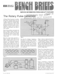
SERVICE INFORMATION FROM HEWLETT-PACKARD
1st Quarter 1988
Using Copper Tape to Fabricate RF
Breadboard Circuits
John Kristiansen
Hewlett-Packard
Introduction
Do you use insulated wire when
breadboarding your circuit boards?
Do you also use insulated wire for
high frequency circuits-for example,
above 50 MHz? At these higher frequencies your wire begins to look
like an inductor, and the whole circuit
may start to oscillate at the slightest
disturbance.
In this article I will describe another
method of breadboarding RF circuits
using adhesive-backed copper tape.
Some of the advantages of using
copper tape are:
The copper tape does not look like
an inductor at high frequencies
Circuit Layout
If it’s not already done, the first
step is to mark your schematic with
component reference designators,
connector pin numbers, test point
designations, etc., to identify all items
and components that will appear on
the layout (see Figure 1 for a simple
schematic). You can start the initial
layout by arranging a rough sketch
of the circuitry to determine the most
practical placement of components
and traces. The next step is to adapt
the sketch to a formal layout using a
grid and a component template that
will establish very accurate conductor
paths, component body outlines, board
outline and all other features. The
layout should be drawn as viewed
from the component side of the
printed circuit board. The actual size
board layout is based on a 0.100 grid
pattern; however, the preferred scale
for paper layout is 2:l.
The 2:l scale is easy to accomplish
using 0.200 grid graph paper (sometimes called “engineering notebook
paper), which is what I used for this
article. Mark your sheet of graph
paper with sequential numbers across
the top and down the side. As you
lay your circuit out on the graph
paper, each component lead (solder
point) assumes a cross-reference
number. These cross-reference numbers will be used for transferring the
layout from the paper to the breadboard so you know where to place
each component and the copper tape.
An example is shown in Figures 2
and 3.
A standard comDonent temdate is
one of the most useful pieces of
The circuit is more stable at high
frequencies-the tendency toward
oscillation is minimized.
The breadboard circuit is similar
in appearance to the final printed
circuit board
The circuit is easier to trace and
troubleshoot
It is easier to make circuit changes
on the board
Copper tape is useful in building
microwave stripline filters, bidirectional couplers, etc.
Figure 1. Sample circuit of inverting gain amplifier.
Pub. No. 5952-0131
WWW.HPARCHIVE.COM
@ Hewlett-Packard 1988
equipment you will use in designing
breadboards. It not only saves valuable time but also assures that standard component lead spacing and body
sizes are used. There are several
models and styles available, one of
which is shown in Figure 4.
If you don't use the template, the
amount of space the component takes
up is a matter of educated guesswork.
For example, if you are using a
predrilled breadboard (with the
standard 0.100 inch spacing), you can
lay a selection of components (with
the leads already bent) on the breadboard and note how many holes are
spanned. For example, a small precision resistor will span four or five
holes. Larger components naturally
span more holes. If you are using a
solid breadboard without predrilled
holes, you are almost forced into
using the template or using the graph
paper to determine the size of your
components.
__
-
-
--1--_
_
A
d
_
Figure 2. Initial graph paper layout of the PC board-component side
The next step is to take all the
component designators you have
noted on the circuit and record them
on a plain sheet of paper. Place
double-sided adhesive tape on the
back side of the paper under the
numbers and set the sheet aside. It
will be used later as the components
are placed on the breadboard.
In the next steps, you need a way to
transfer the cross-reference points
from the paper to the breadboard you
are using. The boards we use a t
Hewlett-Packard are predrilled in a
grid pattern on 0.100 inch centers
(see Figure 5). You can also buy this
type of breadboard at any good electronics store. Other common types of
breadboard available are solid epoxyfiberglass or phenolic material with
a sheet of copper ground plane bonded
to one side. The following procedure
will work equally well on both types
of board. The only difference is that
the solid board requires more work
in matching the reference points from
the graph paper layout to the board,
and in drilling the holes and undercutting the copper ground plane away
from the holes.
2 BENCH BRIEFS
'"7
I
&
3
V
S
b
7
6
?
10
I
la
fJ
IC
/t
/b
It
Ir
It
LO
d1
22
aa
29
or
a&
27
2I
-
_,.-
- - --__-
-r-l
p
-
I
ST
3s
- -Figure 3. Initial graph paper layout of the PC board-copper tape side. The 45" guide line
aids in finding cross reference numbers
WWW.HPARCHIVE.COM
1ST QUARTER
1
have access to smaller drills, I find
that #67 bits are the right size for
IC sockets, #65 for %-?4watt resistors
and diodes, and #60 to #55 for larger
leads. If possible, use a Dremel drill
press to be sure the holes are vertically aligned. This method is also
less likely t o break the brittle carbide
bits. The #60 drill will be a little big,
but it will do for most of the components, including the printed circuit
board sockets. Drill the holes with
the drill and then ream each hole
with an U8-inch drill to undercut the
copper away from the edge of the
hole t o keep the component lead from
shorting to the ground plane (see
Figure 7). Any holes that are meant
to be grounded can be left as is. You
can solder the lead directly to the
ground plane.
Marking Predrilled
Breadboards
Put a strip of tape across the top and
down the side of the board. Use any
type of tape that is easy to write on.
I use self-sticking typewriter correction tape that is commonly found in
the office supplies cabinet. Mark the
same sequential numbers on the
breadboard so it matches the graph
paper. See the example in Figure 6.
bits very quickly, so carbide bits are
usually used for production work.
Phenolic boards are much easier to
drill. If you are limited to a standard
drill bit index, with the smallest drill
being a #60 (0.040 inch), you want
to choose a size that will fit most of
the components you are using. If you
Circuit Board Layout
Figure 5. Typical PC board with holes
predrilled on 0.100 grid
Figure 6. Board layout showing
copper tape in place. Note mylar
insulator where copper tape crosses
At this point, if you were using the
wire method, you would begin loading
the components on the board and
wiring the connections. However,
with copper tape, you lay the tape
first then place the components.
Marking Undrilled
Breadboards
Use the 0.100 or 0.200 inch graph
paper and cut off small strips wide
enough on which to write your numbers and as long as each edge of the
board. Tape them to all four edges of
the board. If you are using 0.200 inch
paper, divide each square in half.
The graph paper will provide you
references in which to draw lines
across the board, allowing you to
transfer your graph paper layout to
the board.
When drilling the holes to mount the
components, you will find that the
epoxy-fiberglass board (commonly
called G-10) will dull ordinary drill
1ST QUARTER
WWW.HPARCHIVE.COM
BENCH BRIEFS 3
Cut off a piece of copper tape the
same length as the board with a pair
of scissors or X-ACTO knife. Next,
use the X-ACTO knife and a good
straight edge (I use a small metal
ruler) and score the tape lengthwise
in approximately 0.800 inch strips
(slightly smaller than the 0.100 grid
pattern), being careful not to cut
through the adhesive backing tape.
The narrow copper strips will easily
lift off the backing tape and lie
perfectly across the holes in the
breadboard.
Start at a convenient location on
your circuit and lay one end of the
tape over the cross-reference number
that matches your graph paper layout. Align the tape over the holes
following the same path as the signal
or Vcc line on the graph paper and
press into place on the circuit board.
Where one piece of copper tape crosses
another, use a small piece of mylar
tape as an insulator. See Figure 6.
Where the junction of two pieces of
copper tape (corners, power taps, continuations) need to make good electrical contact, always solder the
connection. Do not rely on t h e
adhesive.
Figure 7. Undercutting copper away
from hole
At each spot on the board where a
component lead is to be soldered,
poke a hole through the tape from
the tape side of the board using a
plastic-capped bulletin board pin. Insert the permanent components (such
as IC and transistor sockets) and
solder them in place where they poke
through the tape. For those components that you are going to handselect to fine-tune the circuit, use the
printed circuit board sockets listed in
Table 1.Enlarge the breadboard holes
slightly from both sides of the board
with the plastic-capped pin. If you
drilled the holes with a #60 drill, the
socket will probably fit without enlarging the hole. Insert a socket in
the hole (it is easier to insert the
socket if you use a small pair of
needle nose tweezers), and press it
home with the pin. The socket has a
closed end so it will not fill with
solder or flux when you solder it in
place. Components that require frequent replacing can now be easily
inserted and removed without soldering. As you are inserting the components, cut the matching component
designators from the recorded sheet
and paste them on the breadboard
next to the component. When you are
done, your breadboard looks very
similar to a printed circuit board
instead of the usual "rats nest" of
wires. The next issue of Bench Briefs
will contain detailed calculations and
instructions on how to use the copper
tape t o build a common stripline
filter.
0
"1
Table 1. List of References
Description
Roll of Adhesive-Backed
Copperfoil Tape 1" Wide
Roll of Adhesive-Backed
Copperfoil Tape 314" Wide
Roll of Clear Mylar Tape
With Yellow Adhesive
Roll of Clear Mylar Tape
With Clear Adhesive
HP P/N
3M Scotch
#1181
Permacel
# P-391
3M Scotch
#8428
3M Scotch
0460-0762
-
-
#850
Terminal Test Point
0.038 Square
0360-0535
Printed Circuit
Board Socket
0.038" OD
Socket Size
0.03
Bishop
Graphics
#3367
1251-1556
P.C Design Template I
2X (2:l) Scale
The Design & Drafting
of Printed Circuits
4 BENCH BRIEFS
-
John Kristiansen
John Kristiansen, a native of Denmark, joined Hewlett-Packard in 1984
and is working as a bench technician
at HP Labs in the thin film department for disc storage technology. John
enjoys 8mm sound film as a hobby, is
married, has two boys and lives in
Sunnyvale, California.
by Darryl
Lindsey
Pub. by
Bishop
Graphics
WWW.HPARCHIVE.COM
I
3
1ST QUARTER
q
Attention
HP 8671/72 and
8673 Synthesized
Signal Generator
Owners
This issue of Bench Briefs contains
new service notes that describe procedures for improving performance
and protection, and tips on troubleshooting the microwave signal path
of your generators.
Safety-Related
Service Notes
/1
Service notes from HP relating to
personal safety and possible equipment damage are of vital importance to our customers. To make you
more aware of these important
notes, they are printed on paper
with a red border, and the service
note number has a “-S’ suffix. In
order to make you immediately
aware of any potential safety problems, we are highlighting safetyrelated service notes here with a
brief description of each problem.
Also, in order to draw your attention to safety-related service notes
on the service note order form at the
back of Bench Briefiq, each appropriate number is highlighted by being
printed in color.
For example, the rectifier assembly
is a common unit in the HP 867U72
and 8673 series of generators. Several
service notes in this issue describe
troubleshooting procedures to test if
the diodes are shorted to the heat
sink through a damaged anodized
surface. If the surface is damaged,
instructions are provided for placing
a mica insulating washer between
t h e h e a t sink and each of t h e
rectifiers.
the HP 8673B/C/D/E series of generators that help determine whether a
fault is in the ALC circuitry or in the
microwave signal path. To aid in MW
path troubleshooting, the service note
provides signal levels at various test
points that reference back to the
main troubleshooting section in the
operating and service manual.
These service notes are free, just use
the order form at the rear of Bench
Briefs .
0
Detailed microwave signal path
troubleshooting tips are provided for
The HP 3562A operates within the
safety standard for leakage current
when operated within the stated line
frequencies of 48 to 66 Hz. Therefore,
make certain the instrument is operated only within these specified ac
line frequencies of 48 to 66 Hertz.
For more information, order safety
service note 3562A-09-S using the
Bench Briefs’ order form. The note
describes a kit (HP P/N 0356244405)
containing a label to attach to the
rear panel of the instrument.
/
H P 9571A Digital Test
Station
A potential shock hazard may exist
if the power line ground connection
to a protective earth terminal is
defeated. Product Safety Service Note
9571A-25A-S reemphasizes t h i s
warning and describes a label (HP
P/N 7121-4972) to be attached to the
input power module near the access
plate. Order this safety service note
from this issue of Bench Briefs.
/
H P 3562A Dynamic
Signal Analyzer
‘3
Product Safety Service Note
3562A-09-S describes a possible safety
hazard that may exist if the instrument is operated at a nominal line
frequency of 400 Hz and the protective
earth ground is defeated. In these
instances, the HP 3562A exceeds the
3.5 mA leakage current limit (by .7
mA) safety standard.
IST QUARTER
r
-
Model 3562A
WWW.HPARCHIVE.COM
BENCH BRIEFS 5
HP 85043A/B System
Cabinets
Some of the cabinets may have
improperly stripped wires that are
connected to the circuit breakers and
upplement to
terminal block. In these cases, the
fastening screw pushes through the
insulation making a poor contact
with the wire. There have been two
instances where these improperly
stripped wires have caused the circuit
breakers and wire insulation to fail
due to overheating.
HP 435B POWER METER
HP 3779C/D PRIMARY MULTIPLEX
ANALYZERS
435E-3. All serials. Preferred replacement for capacitors
A4C6 and A4C30.
HP 436A POWER METER
436A-12. All serials. Preferred replacement for capacitors A2C4 and A2C6.
HP 438A POWER METER
Need Any Service
Notes?
HP 3780A PATTERN GENERATOWERROR
DETECTOR
HP 1340A DISPLAY
3780A-33. Serials 2524UO3804-2524UO3933 inclusive.
Possible faulty capacitors A30C1 and A30C2 with
date code 8643L on A30 power supply assembly.
1340A-8. All serials. Modification to prevent high voltage
oscillator malfunction.
HP 1345A DIGITAL DISPLAY
HP 1349A/D DIGITAL DISPLAY
Here's the latest listing of service
:s. They recommend modifications
3ewlett-Packard instruments to
'ease reliability, improve performe, or extend their usefulness.
the form at the rear of Bench
charge, service
:s for several instruments.
?fs to order, free of
ou would like to purchase large
ntities of service notes covering
ride range of instruments, or if
desire a complete history of all
rice notes documenting all changes
our instruments, Hewlett-Packard
rs a microfiche library for a one
e charge. There is also a microfiche
scription service available that
omatically updates the library on
iarterly schedule.
: part numbers for the service
microfiche library and subscripI service are:
B
raryscription service-
5951-6511
5951-6517
itact your local HP Sales Office
0
ordering information.
ENCH BRIEFS
37790-36. All serials. Recommended power transistor
replacement on A29 power supply assembly.
3779D-41. All serials. Conversion of HP 3779D option
002 to HP 3779D option 001.
3779D-42. All serials. Recommended power transistor
replacement on A29 power supply assembly.
438A-6. All serials. Preferred replacement for capacitors
A4C13 and A4C15.
1345A-8. All serials. Modification to prevent high voltage
oscillator malfunction.
They're free!
For more information, please order
safety service note 85043B-01-Sfrom
this issue ofBench Briefs.
0
1349AfD-5. All serials. Modification to prevent high
voltage oscillator malfunction.
HP 1650A/1651A LOGIC ANALYZER
1650Af1651A-1.1650A serials: 2722A00535 and below;
1651A serials: 2723A00180 and below. 22OV fuse
change to Slo-610 type.
1650N1651A-3. 1650A serials 2722A00833 and below:
1651A serials 2723A00313 and below. Intensity
adjustment cable modification.
HP 3 2 3 W E SWITCHREST UNIT
3235NE-5. All serials. HP 3235A Firmware Revisions.
3235NE-6. 3235A serials 2725A00626 and below;
3235x serials 2725A00562 and below. Additional
RAM for HP 3235A processor.
HP 3488A SWITCH/CONTROL UNIT
3488A-11B. All serials. Clarification on correct line
fuses.
HP 3552A TRANSMISSION TEST SET
3552A-17. Serials 26151106653 and below. Preferred
replacement for 12V battery packs.
HP 3562A DYNAMIC SIGNAL ANALYZER
HP3562A49-S. Serial prefix 2738A and below. Leakage
current exceeds safety standard at line frequency
of 400 Hz.
HP 3746A SELECTIVE LEVEL
MEASURING SET
3746A-4A. All serials. Retrofit procedure for adding
option 012 tracking generator.
3746A-26. All serials. Preferred replacement for A32Q22
dual FET.
3746A-27. All serials. Preferred replacement for diodes
A5CR1-4, AlOCRI-4 and special option H40
A410CR1-4.
HP 3764A DIGITAL TRANSMISSION
ANALYZER
3764A-22A. Serials 2712U01594 and below. Preferred
replacement of A3 or A3 (option 001/005)
assembly.
WWW.HPARCHIVE.COM
HP 3781A/B PATTERN GENERATOR
3781A-5. Serials 2524UOO837-2704UOO886 inclusive.
Possible faulty capacitors A30C1 and A30C2 with
date code 8643L on A30 power supply assembly.
3781 6-1 1. Serials 2523U01091-2703U01170 inclusive.
Possible faulty capacitors A30C1 and A30C2 with
date code 8643L on A30 power supply assembly.
HP 3782A/B ERROR DETECTOR
3782A-7. Serials 2524UOO832-2524UOO876 inclusive.
Possible faulty capacitors A30C1 and A30C2 with
date code 8643L on A30 power supply assembly.
37828-12. Serials 26361101126-2703U1215 inclusive.
Possible faulty capacitors A30C1 and A30C2 with
date code 8643L on A30 power supply assembly.
HP 3785A/B JITTER GENERATOR
AND RECEIVER
3785A-21. Serials 2519UOO646-2519U00718 inclusive.
Possible faulty capacitors A30C1 and A30C2 with
date code 8643L on A30 power supply assembly.
37856-19. Serials 2518U00651-2518U00710 inclusive.
Possible faulty capacitors A30C1 and A30C2 with
date code 8643L on A30 power supply assembly.
HP 37878 DIGITAL DATA TEST SET
37876-2. Serials 2703U00206 and below. Elimination
of spurious pulses from D S I / l C Rx input (A5;
U520).
37876-3. All serials. Conversion of HP 37876 standard
to option 001 jitter measurement capability.
HP 4938A NETWORK CIRCUIT ACCESS
TEST SET
4938A-2A. Serials 2450A00702 and below. Modification
to correct a potential failure.
HP 4948A IN-SERVICE TRANSMISSION
MEASURING SET
4948A-2. A8/A11 schematic diagram correction.
4948A-3. All serials. Preferred replacement part number
for A7 tray retaining screw MP61.
4948A-5. All serials. Preferred replacement for display
module MP7.
HP 4952A PROTOCOL ANALYZER
4952A-2A. Serials 2725A and below, and 2739F and
below. Improved yoke assembly.
4952A-3A. Serials 2726A01194 and below, and serials
2635F20001 thru 2635F20454. Modification to fix
potential disc access problem (non LIF format. disc
out, disc error).
1ST QUARTER
c
HP 4954A PROTOCOL ANALYZER
fl
4954A-1. Serial number range listed in text of note.
Firmware revision 1.1 upgrade to correct critical
bugs and intermittent failures.
4954A-2. Serial number range listed in text of note.
Replacement of A5 U701 board enable driver.
HP 8160A PROGRAMMABLE
PULSE GENERATOR
8160A-14. Serials 2650G00746 to 2650600785 inclusive. Possible short of HP-IB REN line to ground
causes unit to stay remote operation when addressed
to listen.
HP 81808 DATA GENERATOR
81806-1A. Serials 2640G00100 to 2640G00148. Improved firmware revision.
HP 8481A POWER SENSOR
8481A-5. All serials. Curing intermittent operation.
HP 8559A SPECTRUM ANALYZER
8559A-31. Serial prefix 2819A and below. Redesigned
sweep generator board with improved +10 volt
reference power supply to provide improved
performance.
HP 8566A SPECTRUM ANALYZER
8566A-206. All serials. HP 8566AB retrofit kit instructions (formerly 8566A+01 K).
HP 85668 SPECTRUM ANALYZER
85666-11A. All serials. HP 8566AB retrofit kit (formerly
8566A+01K).
HP 8568A SPECTRUM ANALYZER
8568A-448. All serials. HP 8568AB retrofit kit instructions (formerly 8568A+01 K).
HP 85688 SPECTRUM ANALYZER
."7
85686-12A. All serials. HP 8568AB retrofit kit (formerly
8568A+01K).
HP 8590A SPECTRUM ANALYZER
8590A-2A. All serials. Option H50 CATV retrofit installation instructions.
8590A-5. All 75 Ohm input options (001). Instructions
to correct the HP 8590A 75 Ohm option 001 readout
from d6m to d6mV after replacing firmware ROMs.
859OA-6. All 75 Ohm input options (001). 50 Ohm
input. List of programs to correct or change the
CRT readout from dBm to dBmV or from dBmV to
dBm.
8590A-7. All serials. Display modifications to improve
performance.
HP 8642AIB SYNTHESIZED
SIGNAL GENERATOR
8642A-6/8642B-6. A14 module serial prefixes 2531A
and below. Modification to resolve low output power
in the Heterodyne band.
HP8642B-7. A19 module serial prefixes 2517A to
2640A inclusive. A1 9 doublerlattenuator module
replacement for maximum output level degradation.
HP 8662A SYNTHESIZED
SIGNAL GENERATOR
8662A-12C. Serial prefix 2429A and below. Modification
to improve low frequency loop performance and
eliminate intermittent status errors 03/04.
8662A-15. All serials. Instructions for replacing the
cooling fan.
HP 8663A SYNTHESIZED
SIGNAL GENERATOR
8663A-6C. Serial prefix 2424A and below. Modification
to improve low frequency loop performance and
eliminate intermittent status errors 03/04.
8663A-9. All serials. Instructions for replacing the
cooling fan.
HP 86718 SYNTHESIZED
SIGNAL GENERATOR
86716-2. Serial prefix 2703A and below. Add mica
insulators under diodes A3A12CR13 and
A3A12CR14.
86718-03, All serials. Preferred replacement for precision resistors.
1ST QUARTER
HP 8672A SYNTHESIZED
SIGNAL GENERATOR
HP MODEL 9571A
DIGITAL TEST STATION
8672A-19. Serial prefix 2703A and below. Add mica
insulators under diodes A3A12CR13 and
A3A12CR14.
8672A-20. All serials. Preferred replacement for precision resistors.
9571A-25A-S. All senals. Potential shock hazard if the
power line ground connection to a protective earth
terminal is defeated.
HP 86738 SYNTHESIZED
SIGNAL GENERATOR
86736-11. Serial prefix 2704A and below. Add mica
insulators under diodes A3A12CR13 and
A3A12CR14.
86738-12. All serials. Instructionsfor microwave signal
path troubleshooting.
86738-13. Serial prefix 2640A through 2735A inclusive.
Modifications to improve power supply reliability.
86738-14. All serials. Preferred replacement for precision resistors.
HP 8673C SYNTHESIZED
SIGNAL GENERATOR
8673C-12. Serial prefix 2703A and below. Add mica
insulators under diodes A3A12CR13 and
A3A12CR14.
86730-13. All serials. Instructionsfor microwave signal
path troubleshooting.
86730-14. Serial prefix 2640A through 2735A inclusive.
Modifications to improve power supply reliability.
8673C-15. All serials. Preferred replacement for precision resistors.
HP 867313 SYNTHESIZED
SIGNAL GENERATOR
8673D-13. Serial prefix 2703A and below. Add mica
insulators under diodes A3A12CR13 and
A3A12CR14.
8673D-14. All serials. Instructionsfor microwave signal
path troubleshooting.
8673D-15. Serial prefix 2640A through 2735 inclusive.
Modifications to improve power supply reliability.
8673D-16. All serials. Preferred replacement for precision resistors.
HP 8673E SYNTHESIZED
SIGNAL GENERATOR
8673E-5. Serial prefix 2704A and below. Add mica
insulators under diodes A3A12CR13 and
A3A12CR14.
8673E-6. All serials. Instructions for microwave signal
path troubleshooting.
8673E-07. Serial prefix 2640A through 2738A inclusive.
Modifications to improve power supply reliability.
8673E-08. All serials. Preferred replacement for precision resistors.
HP 37204N8 HP-I8 EXTENDER
37204A-02. Serials 25471103590 and below. Modification to correct power supply failure when both
port fault lamps stay on.
37204641, Serials 26261100450 and below. Modification to correct power supply failure when both
port fault lamps stay on.
HP 54110D DIGITIZING OSCILLOSCOPES
54110D-9. Serial prefixes 2710A and below. New
analog power supply offers family compatability.
54110D-10. Serial prefixes 2710A and below. New
primary power supply offers family compatability
and improves reliability.
HP 54111D DIGITIZING OSCILLOSCOPES
541 11D-3. Serial prefixes 2719A and below. New
primary power supply offers family compatability
and improves reliability.
HP 54112D DIGITIZING OSCILLOSCOPE
541 12D-1A. Serials 2735A00173 and below. Modification to prevent loss of resolution or excessive
noise on trace.
HP 54120T DIGITIZING OSCILLOSCOPES
54120T-6. All serials. How to obtain semi rigid "S'
and
semi rigid "U" cables used for test and adjustment.
HP 54201ND DIGITIZING OSCILLOSCOPES
54201ND-10. All serials. Locked high trace or rx) trace
may be result of input FET failure.
54201ND-11. Serial prefixes 2716A and below. Improved input FET protection available.
54201ND-12. All serials. Software calibration procedure
summary.
HP 70900A LOCAL OSCILLATOR
70900A-146. All serials. H a r d w a d f i r m w a r e
compatibility.
HP 85029A VERIFICATION KIT
85029A-1. All serials. Transferring data files from
replacement disc to the master disc.
HP 85043AIB SYSTEM CABINETS
850436-1-S. 85043A serials 2622A01352 and below,
and 850436 serials 2623A00172 and below. Elimination of a potential safety hazard in the circuit
breakers.
HP 8753A NETWORK ANALYZER
HP 85046AIB SPARAMETER TEST SET
8753A-1. All serials. Instructions for creating A9 EEPROM backup data.
8753A-618757A-5. 8753A serials 2625A and below,
2625J and below, 2713U and below, and 8757A
serials 2646A and below. Modification to prevent
dust accumulation on the CRT and glass filter.
8753A-7A. All serials. A3 source/A9 CPUiAl 1 phaselock
assembly compatibility matrix.
8753A-8. All serials. Firmware update/replacement kit
(HP P/N 08753-6OXXX).
8753A-9. All serials. Revision A.O1 performance test
software.
85046NB-1. 85046 serials 2542A01553 and below,
and 850466 serials 2542A00220 and below. Modification to make sure attentuator andlor RF switch
actuates.
HP 8757A SCALAR NETWORK ANALYZER
8757A-6. All serials. Modification to prevent intermittent
memory loss.
HP 8902A MEASURING RECEIVER
8902A-5.Serial prefixes 2741A and below. Modification
to resolve set reference error.
HP 850518 7 MM VERIFICATION KIT
850516-1. Serials 2705A00001 through 2705A00162
certifiedlrecertified before Oct. 1987. Exceptions:
2705A00137, 2705A00139, 2705A00146,
2705A00147, 2705A00150, 2705A00152,
12705A00154, 2705A00159, 2705A00160,
2705A00161. Modification to prevent possible
damage to the 50 Ohm airline (pari number
85051-60007) and 25 Ohm mismatch airline (part
number 85051-60008) when used with the HP
85050C 7 MM precision calibration kit).
HP 85629A TEST AND
ADJUSTMENT MODULE
85629A-1A. All serials. New ROM upgrade kit (HP
P/N 85629-60002)
HP 8970AIB NOISE FIGURE METER
HP 85685A RF PRESELECTOR
8970A-12. All serials. Preferred replacement for oscillator transistor A1 1Al Q1.
89706-2. All serials. Preferred replacement for oscillator
transistor A1 1A1 Q1.
85685A-13. Serial prefixes 2620A and below. Instructions for installing susceptibility improvement kit.
85685A-15. Serial prefixes 2620A and below. Instructions for installing residual improvement kit.
WWW.HPARCHIVE.COM
BENCH BRIEFS 7
rice Note Order Form
:
For European customers (ONLY)
Name
Hewlett-Packard
Nederland BV
Central Mailing Dept.
P.O.Box 529
1180 AM Amstelveen
The Netherlands
Firm
r
)
State
Zip
0 8757A-6
0 8902A-5
0 8673D-13
0 8673D-14
0 8673D-15
0 8970A-12
0 86718-2
0 86718-03
0 8673D-16
0 8673E-5
0 37204A-02
0 37204501
0 8672A-19
0 8673E-6
0 8673E-07
0 5411oD-9
0 54110D-10
0 8673E-08
0 54111D-3
+3-w5M+
0 8753A-618757A-5
0 8753A-7A
0 8753A-8
0 8753A-9
0 54112DlA
0 864257
0 4954A-2
0 8160A-14
0 8180B-1A
0 8481A-5
0 8662A-12C
0 8559A-31
0 8566A-208
0 85668-11A
0 8568A-448
0 85688-12A
0 8672A-20
0 8673511
0 8590A-2A
0 86738-12
0 8590A-5
0 8590A-6
86738-13
0 8673514
0 8673012
0 8673013
0 8662A-15
0 8663A-6C
0 8663A-9
0 8642A-6186428-6
City
0 8673C-14
0 8673015
0 4954A-1
0 8590A-7
Address
0 89708-2
0 9571A-25A-S
5412OT-6
0 54201ND-10
0 54201ND-11
0 54201ND-12
0 70900A-148
0
0
0
0
Please photocopy this order form if you do not
want to cut off the page
85029A-1
85043514
85046NB-1
850518-1
0 85629A-1A.
0 85685A-13
0 85685A-15
Bulk Rate
U S Postage
Sunnyvale, CA
Permit No
All rights reserved Permission lo reprinl Bench Briefs granted upon written requesl to the Editor
WWW.HPARCHIVE.COM
Printed in U.S.A
1ST QUARTER