1
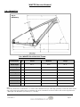
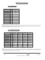
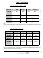
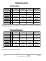
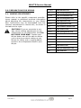
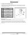
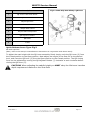
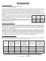
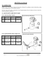
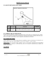
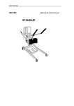
MTB Hardtail Range
29 CS & 29 C Team
405
529 & 629
603, 604 & 605
801, 802, 805 & 806
901, 905 & 909
Supplementary Service Manual
2016 Edition 1
Table of Contents
2016 Edition 1
1.0
Introduction
2.0
Geometry:
2.1:
29 CS & 29 C Team
2.2:
405
2.3:
529 & 629
2.4:
603, 605, 801 & 805
2.5:
604, 802 & 806
2.6:
901
2.7:
905 & 909
3.0
Preparations for riding:
3.1
Making Adjustments
3.2
Getta-Grip Seat Clamp
3.3
Set up of Fork
3.4
Suspension Tuning Log
4.0
Safety.
5.0
Lubrication:
5.1
Whyte Getta-Grip Seat Clamp
5.1.1: Bolt Up
5.1.2: QR Style
5.2
Whyte Inter-grip Seat Clamp
5.3
General Whyte Lubrication
6.0
Torque Settings:
Whyte Whyte Rear Derailleur Hanger
7.0
Notes.
Page 3
WHYTE Service Manual
1.0: INTRODUCTION
Thanks for choosing to purchase this Whyte product. We hope you will enjoy all the benefits its advanced design and engineering will bring to your riding experience.
This manual will guide you through the set-up, safety and maintenance procedures that
are specific to your Whyte bike. For other more general information, we strongly advise
that you also read thoroughly the General Instruction Manual that is also supplied with
your new bike.
Also, please note that the specification of all the components that are fitted to your bike as
standard may be obtained from the Whyte Bikes Brochure or alternatively from the Whyte
Bikes website www.whytebikes.co.uk
Please remember, if you are in any doubt about your ability to safely service or repair your
Whyte bike, do not ride it and instead arrange for a professional bicycle mechanic at your
local Whyte dealer to do the job correctly.
Bundled with this manual, are the respective manufacturers instructions and manuals for
the branded parts that are fitted to your Whyte bike. Please take time to study all the relevant instruction manuals to ensure you have a continually safe and well set-up bike before
every ride, and to help you build up a relationship of knowledge between you and your
Whyte Dealer.
Happy and safe riding,
Whyte design team. May 2015.
Page 4
2016 Edition 1
WHYTE Service Manual
2.0: GEOMETRY
Fig.1:
Geometry
2.1: WHYTE 29 CS & 29 C Team
Frame Size
X
Small
Medium
Large
Head Angle
A
69.3°
69.3°
69.3°
Seat Angle
B
73.0°
73.0°
73.0°
Top Tube
C
612.2mm
627.0mm
640.8mm
BB Height*
D
305mm
305mm
305mm
Stand Over
E
790mm
810mm
845mm
Wheel Base
F
1117.3mm
1127.9mm
1144.9mm
Chain Stay
G
437.5mm
437.5mm
437.5mm
Seat Post
H
30.9mm
30.9mm
30.9mm
Note:
Geometry shown here is ’Showroom’ i.e. without rider aboard the bicycle. ’With Sag’ geometry is with rider after correct
sag is set at the front. Please refer to suspension set up for information on how to achieve the correct sag of the fork.
* BB height with Ø738mm tyres fitted (2.1” / 52-622)
2016 Edition 1
Page 5
WHYTE Service Manual
2.2.2: WHYTE 405
Frame Size
X
13”
Head Angle
A
68.5°
Seat Angle
B
74.0°
Top Tube
C
629.4mm
BB Height*
D
305mm
Stand Over
E
711mm
Wheel Base
F
1068.6mm
Chain Stay
G
425mm
Seat Post
H
30.9mm
Notes:
Geometry shown here is ’Showroom’ i.e. without rider aboard the bicycle. ’With Sag’ geometry is with rider after correct
sag is set at the front. Please refer to suspension set up for information on how to achieve the correct sag of the fork.
* BB height with Ø677mm tyres fitted (2.25” / 54-559)
2.2.3: WHYTE 529 & 629
Frame Size
X
Small
Medium
Large
Extra
Large
Head Angle
A
68.5°
68.5°
68.5°
68.5°
Seat Angle
B
73.0°
73.0°
73.0°
73.0°
Top Tube
C
580.5mm
594.5mm
612.4mm
632.2mm
BB Height*
D
305mm
305mm
305mm
305mm
Stand Over
E
800mm
810mm
836mm
850mm
Wheel Base
F
1123mm
1138mm
1158mm
1178mm
Chain Stay
G
440mm
440mm
440mm
440mm
Seat Post
H
30.9mm
30.9mm
30.9mm
30.9mm
Note:
Geometry shown here is ’Showroom’ i.e. without rider aboard the bicycle. ’With Sag’ geometry is with rider after correct
sag is set at the front. Please refer to suspension set up for information on how to achieve the correct sag of the fork.
* BB height with Ø738mm tyres fitted (2.1” / 52-622)
Page 6
2016 Edition 1
WHYTE Service Manual
2.2.4: WHYTE 603, 605, 801 & 805
Frame Size
X
Small
Medium
Large
Extra Large
Head Angle
A
68.5°
68.5°
68.5°
68.5°
Seat Angle
B
73.5°
73.5°
73.0°
73.0°
Top Tube
C
593.5mm
608.1m
627.9mm
638.8mm
BB Height*
D
303.5mm
303.5mm
303.5mm
303.5mm
Stand Over
E
779mm
797mm
822mm
851mm
Wheel Base
F
1107.1mm
1122.6mm
1137.4mm
1149.1mm
Chain Stay
G
435mm
435mm
435mm
435mm
Seat Post
H
30.9mm
30.9mm
30.9mm
30.9mm
Note:
Geometry shown here is ’Showroom’ i.e. without rider aboard the bicycle. ’With Sag’ geometry is with rider after correct
sag is set at the front. Please refer to suspension set up for information on how to achieve the correct sag of the fork.
* BB height with Ø717mm tyres fitted (2.25” / 52-584).
2.2.5: WHYTE 604, 802 & 806
Frame Size
X
Extra Small
Small
Medium
Large
Head Angle
A
68.5°
68.5°
68.5°
68.5°
Seat Angle
B
74.0°
73.5°
73.5°
73.5°
Top Tube
C
570.6mm
585.5mm
599.6m
613.7mm
BB Height*
D
303.5mm
303.5mm
303.5mm
303.5mm
Stand Over
E
776mm
784mm
804mm
829mm
Wheel Base
F
1089.1mm
1099.1mm
1114.1mm
1129.1mm
Chain Stay
G
435mm
435mm
435mm
435mm
Seat Post
H
30.9mm
30.9mm
30.9mm
30.9mm
Note:
Geometry shown here is ’Showroom’ i.e. without rider aboard the bicycle. ’With Sag’ geometry is with rider after correct
sag is set at the front. Please refer to suspension set up for information on how to achieve the correct sag of the fork.
* BB height with Ø717mm tyres fitted (2.25” / 52-584).
2016 Edition 1
Page 7
WHYTE Service Manual
2.2.6: WHYTE 901
Frame Size
X
Small
Medium
Large
Extra Large
Head Angle
A
66.5°
66.5°
66.5°
66.5°
Seat Angle
B
73.0°
73.0°
73.0°
73.0°
Top Tube
C
619mm
638mm
655mm
674mm
BB Height*
D
305.0mm
305.0mm
305.0mm
305.0mm
Stand Over
E
778mm
794mm
816mm
833mm
Wheel Base
F
1139mm
1169mm
1178mm
1204mm
Chain Stay
G
425mm
425mm
425mm
430mm
Seat Post
H
30.9mm
30.9mm
30.9mm
30.9mm
Notes:
Geometry shown here is ’Showroom’ i.e. without rider aboard the bicycle. ’With Sag’ geometry is with rider after correct
sag is set at the front. Please refer to suspension set up for information on how to achieve the correct sag of the fork.
* BB height with Ø717mm tyres fitted (2.25” / 54-584)
2.2.7: WHYTE 905 & 909
Frame Size
X
Small
Medium
Large
Extra Large
Head Angle
A
66.5°
66.5°
66.5°
66.5°
Seat Angle
B
73.0°
73.0°
73.0°
73.0°
Top Tube
C
619mm
638mm
655mm
674mm
BB Height*
D
305.0mm
305.0mm
305.0mm
305.0mm
Stand Over
E
770mm
805mm
832mm
861mm
Wheel Base
F
1139mm
1169mm
1178mm
1204mm
Chain Stay
G
425mm
425mm
425mm
430mm
Seat Post
H
30.9mm
30.9mm
30.9mm
30.9mm
Notes:
Geometry shown here is ’Showroom’ i.e. without rider aboard the bicycle. ’With Sag’ geometry is with rider after correct
sag is set at the front. Please refer to suspension set up for information on how to achieve the correct sag of the fork.
* BB height with Ø717mm tyres fitted (2.25” / 54-584)
Page 8
2016 Edition 1
WHYTE Service Manual
3.0: PREPARATIONS FOR RIDING
3.1: MAKING ADJUSTMENTS
Please refer to the specific component manufacturers manual or published technical information
about adjusting the components on your Whyte
bike. Instructions may be downloaded from the
relevant manufacturer’s internet site, as shown in
the table to the right.
CAUTION! If you are uncertain in any
way, about making adjustments to any
components on you Whyte bike, then DO
NOT RIDE YOUR BIKE. Contact your
Whyte dealer who will be able to advise
you on how to go about setting up you
Whyte for riding, and or making adjustments to the components fitted to your
Whyte.
2016 Edition 1
DT Swiss
www.dtswiss.com
FSA
www.fullspeedahead.com
Formula
www.formulahubs.com
Fox
www.foxracingshox.com
Hope
www.hopetech.com
Jagwire
www.jagwireusa.com
Jalco
www.maddux-wheels.com
Maxxis
www.maxxis.com
Prologo
www.prologotouch.com
Race Face
www.raceface.com
Shimano
www.shimano.com
SR Suntour
www.srsuntour-cycling.com
SRAM
www.sram.com
Tektro
www.tektro.com
VP
www.vpcomponents.com
WTB
www.wtb.com
Page 9
WHYTE Service Manual
3.2: WHYTE GETTA-GRIP SEAT CLAMP
The Getta Grip seat clamp design is a patented design to allow adjustment of the saddle
height by either the use of a Quick Release (QR) Lever, or bolt-up method. This manual
covers both styles of clamps.
Fig.2: Getta-Grip Seat Clamp: Bolt-up
Item:
Description
1
Whyte Seat Clamp Band
2
T-Pad
3
Whyte Main Frame Seat Tube
4
Adjuster Nut
5
M6 x 25mm Long Fastener
6
M6 Washer
Bolt-up Type: Fig.2
Tools Required:
5mm Allen Key
(Note, refer to the seat-pin manufacturers instructions in conjunction with these notes).
To adjust the seat height, using the 5mm Allen key, undo the M6 bolt (5) just enough to allow
the seat-pin to slide freely up and down. Set the height to the desired level, and re-tighten the
M6 bolt (5) with the 5mm Allen Key just enough so as to prevent the seat-pin from slipping down
and twisting.
Page 10
2016 Edition 1
WHYTE Service Manual
Item
Description
1
QR Lever Cam Grub Screw
2
QR Lever Cam
3
Whyte QR Lever
4
Plastic Shim
5
Whyte Main Frame
6
Whyte Seat Clamp Band
7
QR Adjuster Bobbin
8
QR Shaft
9
T-Pad
Fig.3: Getta-Grip Seat Clamp: QR Lever
Quick Release Lever Type: Fig.3
No tools required.
(Note, refer to the seat-pin manufacturers instructions in conjunction with these notes).
To Adjust the seat height with the QR Lever assembly fitted, simply undo the QR Lever (3) from
the Closed position to the Open position. Next adjust the height of the Seat Pin to the desired
level, and close the QR lever (3) from the Open position to the Closed position. The QR closing
force can be adjusted by turning the QR Adjuster Bobbin (7) clockwise or anti-clockwise before
closing the QR Lever (3).
CAUTION! When adjusting the saddle height you MUST obey the Minimum insertion
depth requirement marked on the Seat Post.
2016 Edition 1
Page 11
WHYTE Service Manual
3.3: SET UP OF FORK
Tools Required:
Good Quality Shock Pump.
Small Ruler
The front suspension fork fitted to your Whyte bike will be pre-set with the standard settings. Before
riding, you may need to adjust these setting. First is the Sag setting on the fork. This is to ensure
the forks are set-up correctly for your own body weight, so the fork will perform as intended.
To set Sag on the front fork, you need to measure the amount the fork compresses when you sit on
the bike in the normal riding position. See the table on the right for our recommendation of front
fork sag on your Whyte bike. To achieve this you will need to adjust the air spring pressure inside
the fork.
Refer to the specification tables in this manual, and then to the releSag
Sag
Fork
vant fork manufacturers set up instructions to find how to adjust the
(15% (25% air spring pressure in the fork. Using a shock pump, either add or Travel
Firm)
Plush)
remove air until Sag is correctly set.
Please note that for the detailed instructions for servicing and all mat- 100mm
15mm
25mm
ters relating to the forks fitted to your Whyte bike, please refer to the
manufacturers instructions.
130mm 19.5mm 32.5mm
Rebound Damping adjustment:
This adjustment fine-tunes the speed at which the wheel returns to its normal ride height after
hitting a bump. Refer to the relevant manufacturers instructions to find out how to adjust the rebound damping. To demonstrate the effect of this function, turn the adjuster to its slowest setting.
Press down on the handlebars to compress the forks, then release the load. The suspension recovers
very slowly to its original position.
Repeat the above with the adjuster turned to the fastest setting and the difference will be seen
immediately the load is released. We recommend the optimum setting is to adjust the re-bound
damping to be as slow as possible, but not so slow that the normal ride height is not recovered. On
very rough terrain, if the bike becomes progressively lower as more bumps are hit then the rebound damping is set too slow. On the other hand if the bike feels choppy and not plush then the rebound damping is too fast. A bit of trial and error is needed to get the exact setting.
3.4: SUSPENSION TUNING LOG
Record your best suspension settings in the table below, to restore them if necessary, eg. after dealer servicing of the suspension or if a friend has borrowed your bike.
Date
Page 12
Rider Weight
(including all
riding kit)
(kg or lbs)
Fork Pressure
(bar or P.S.I)
Fork Rebound
Damping
(# of clicks from
softest setting)
Shock Pressure
(bar or P.S.I)
Shock Rebound
Damping
(# of clicks from
softest setting)
2016 Edition 1
WHYTE Service Manual
4.0: SAFETY
IMPORTANT: The following are intended to be advisory notes on the safe use of your
Whyte bike. You should also read thoroughly the General Instruction Manual also supplied
with your new bike. If at any stage you are uncertain about the safety or safe operation of
the bike as a whole, or any specific component, then DO NOT RIDE YOUR WHYTE and
instead please consult the specific component manufacturers instruction manual or your
Whyte Dealer for advice.
Maximum Rider Weight Limit for Whyte Hardtail MTB Series’:
19 Stone/120kg
WARNING: As is the case with all mechanical components, the bicycle is subjected
to wear and high stresses. Different materials and components may react to wear
and stress fatigue in different ways. If the design life of a component has been exceeded, it may fail suddenly causing possible injury to the rider. Any form of crack,
scratches and decolouring in highly stresses areas are showing that the component
has exhausted its life time and has to be replaced. If you are in any doubt about one
or more components on your Whyte DO NOT RIDE YOUR BIKE. Consult the specific component manufacturers literature, or take your bike to your local Whyte Dealer.
Designed for the following use:
All bicycles in the Whyte Hardtail MTB series’ have all been designed, tested and comply
with ISO 4210-2 Safety Standard, for typical cross country mountain biking use. They have
not been designed or tested for extreme down-hilling or free-riding.
2016 Edition 1
Page 13
WHYTE Service Manual
5.0: LUBRICATION
Please refer to the Whyte General Instruction Manual for guidance about lubricating many
of the components on your Whyte bicycle.
For the range of bicycles contained in this Supplementary Service Manual, there is also the
following specific guidance:
5.1: WHYTE GETTA-GRIP SEAT CLAMP
5.1.1: Bolt-Up Style. Fig.5a
Fig. 5a: Bolt-Up Lubrication
Point
Description
Lubricant
Lubrication
Interval
1
M6 x 25mm
Fastener
Castrol LM
or
equivalent
Once a
Month
5.1.2: Quick Release Style. Figure 5.b
Figure 5b: QR Lubrication
Point
Description
Lubricant
Lubrication
Interval
1
Lever Cam
Surface
Castrol LM
or
equivalent
After Every
Ride
2
M6 Shaft
Castrol LM
or
equivalent
Once a
Month
Page 14
2016 Edition 1
WHYTE Service Manual
5.2: WHYTE INTER-GRIP SEAT CLAMP
Figure 8: Capscrew Lubrication
Item
Description
Lubricant
Lubrication
Interval
1
M6 x 30mm
Capscrew
SKF LGEP2 or Castrol Spheerol AP3 or Finish
Line Teflon White Lithium Complex grease
Once a Month
5.3: GENERAL WHYTE LUBRICATION
For the correct lubrication regime and maintenance of all parts on a Whyte bicycle, please
refer to the specific component manufacturers detailed instructions bundled with this manual or for further information visit the specific manufacturers website.
6.0: TORQUE SETTINGS
Torque explained: If no suitable Torque Wrench is available a Torque of 5 lbf.ft can be obtained by applying a force of 5lb, with a Spring Balance, to the end of a spanner, 1 Foot in length.
IMPORTANT: For all other torque settings, refer to the specific manufacturers information
bundled with this manual, or alternatively, refer to the specific manufacturers website for
further information.
7.0: NOTES
2016 Edition 1
Page 15