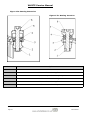
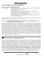
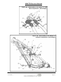
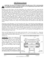
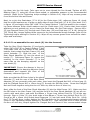
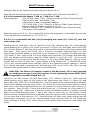
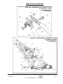
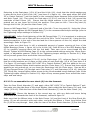
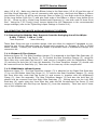
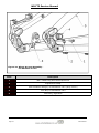
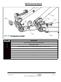
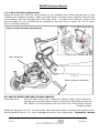
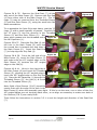
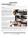
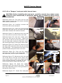
1
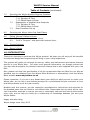
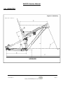
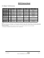
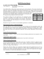
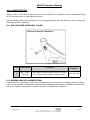
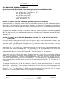
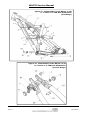
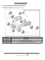
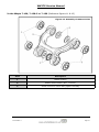
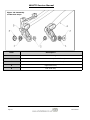
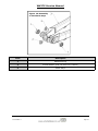
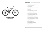
MTB Full Suspension Range
G-160 Works & G-160 RS
T-130-C Works & T-130-C RS
T-130 RS, T-130 S & T-130 SX Women’s Spec
T-129 SCR, T-129 RS & T-129 S
Supplementary Service Manual
2016 Edition 1
Table of Contents
1.0
Introduction
2.0
Geometry:
2.1
G-160 Works & G-160 RS
2.2
T-130-C Works & T-130-C RS. T-130 RS, T-130 S & T-130 SX
Women’s Spec
2.3
T-129 SCR, T-129 RS & T-129 S
3.0
Preparations for riding:
3.1
Making Adjustments
3.2
Whyte Inter Grip Seat Clamp Adjustment
3.3
Set up of Fork
3.4
Set up of Rear Damper
3.5
Suspension Tuning Log
4.0
Safety.
5.0
Lubrication:
5.1
Whyte Inter Grip Seat Clamp
5.2
General Lubrication
6.0
Servicing the Rear Suspension:
6.1
Removing the Rear Shock and Swinging Arm
6.1.1 From G-160
6.1.1.1 Remove the Rear Shock only.
6.1.1.2 Remove the other rear suspension parts.
6.1.2 From T-130-C, T-130 or T-129
6.1.2.1 Remove the Rear Shock only.
6.1.2.2 Remove the other rear suspension parts.
6.2
Stripping and Re-assembling Rear Suspension Bearings
6.2.1 Extraction of Bearings
6.2.2 Insertion of Bearings
6.2.3 Re-Assembly of Shield Washers / Spacers
6.3
Re-assembling the Rear Suspension
6.3.1 Re-Assembly of the Rear Suspension (G-160)
6.3.1.1 Re-assemble the other rear suspension parts.
6.3.1.2 Re-assemble the Rear Shock into the Frameset.
6.3.2 Re-Assembly of Rear Suspension (T-130-C, T-130 or T129)
6.3.2.1 Re-assemble the other rear suspension parts.
6.3.2.2 Re-assemble the Rear Shock into the Frameset.
2016 Edition 1
Page 3
WHYTE Service Manual
Table of Contents (continued)
7.0
Servicing the Whyte Modular Dropout Systems:
7.1
Disassembly of Modular Rear Dropouts
7.1.1 Shimano E-Thru
7.1.2 SRAM Maxle 142mm
7.2
Reassembly of Modular Rear Dropouts
7.2.1 Shimano E-Thru
7.2.2 SRAM Maxle 142mm
7.3
Rear Derailleur Set-up
8.0
Servicing the Whyte Inter Grip Seat Clamp
9.0
Fitting Internal Cables & Hoses.
9.1
To replace cable or hose outers.
9.2
To fit a “Dropper” seat-post with internal hose.
10.0
Torque Settings.
11.0
Owner’s Notes
1.0: INTRODUCTION
Thanks for choosing to purchase this Whyte product. We hope you will enjoy all the benefits
its advanced design and engineering will bring to your riding experience.
This manual will guide you through the set-up, safety and maintenance procedures that are
specific to your Whyte bike. For other more general information, we strongly advise that
you also read thoroughly the General Instruction Manual that is also supplied with your new
bike.
Also, please note that the specification of all the components that are fitted to your bike as
standard may be obtained from the Whyte Bikes Brochure or alternatively from the Whyte
Bikes website www.whytebikes.co.uk
Please remember, if you are in any doubt about your ability to safely service or repair your
Whyte bike, do not ride it and instead arrange for a professional bicycle mechanic at your
local Whyte dealer to do the job correctly.
Bundled with this manual, are the respective manufacturers instructions and manuals for
the branded parts that are fitted to your Whyte bike. Please take time to study all the relevant instruction manuals to ensure you have a continually safe and well set-up bike before
every ride, and to help you build up a relationship of knowledge between you and your
Whyte Dealer.
Happy and safe riding,
Whyte design team. May 2015.
Page 4
2016 Edition 1
WHYTE Service Manual
2.0: GEOMETRY
Figure1: Geometry
2016 Edition 1
Page 5
WHYTE Service Manual
2.1: Whyte G-160 Geometry
Frame Size
X
Small
Medium
Large
Head Angle
A
65.5°
65.5°
65.5°
Seat Angle*
B
74.7°
74.5°
74.3°
Top Tube
C
607.6mm
636.6mm
655.9mm
BB Height**
D
342.5mm
342.5mm
342.5mm
Stand Over
E
808mm
816mm
822mm
Wheel Base
F
1181.7mm
1211.7mm
1231.7mm
Chain Stay
G
425mm
425mm
425mm
Seat Post
H
30.9mm
30.9mm
30.9mm
Notes:
Geometry shown here is ’Showroom’ i.e. without rider aboard the bicycle. ’With Sag’ geometry is with rider after correct
sag is set at front and rear. Please refer to suspension set up for information on how to achieve the correct sag of the
fork and rear damper.
* Effective seat angle, from wheel centres horizontal to line from BB to seat post axis @ top of saddle.
** BB height with Ø717mm tyres fitted (2.25” / 54-584)
2.2: Whyte T-130-C & T-130 Geometry
Frame Size
X
Extra Small
Small
Medium
Large
Extra-Large
Head Angle
A
66.5°
66.5°
66.5°
66.5°
66.5°
Seat Angle*
B
74.0°
73.7°
73.5°
73.3°
73.2°
Top Tube
C
571.7mm
591.4mm
611.1mm
631.0mm
650.7mm
BB Height**
D
331.0mm
331.0mm
331.0mm
331.0mm
331.0mm
Stand Over
E
761mm
763mm
766mm
776mm
776mm
Wheel Base
F
1118.5mm
1136.5mm
1156.5mm
1176.5mm
1196.5mm
Chain Stay
G
420mm
420mm
420mm
420mm
420mm
Seat Post
H
30.9mm
30.9mm
30.9mm
30.9mm
30.9mm
Notes:
Geometry shown here is ’Showroom’ i.e. without rider aboard the bicycle. ’With Sag’ geometry is with rider after correct
sag is set at front and rear. Please refer to suspension set up for information on how to achieve the correct sag of the
fork and rear damper.
* Effective seat angle, from wheel centres horizontal to line from BB to seat post axis @ top of saddle.
** BB height with Ø717mm tyres fitted (2.25” / 54-584)
Page 6
2016 Edition 1
WHYTE Service Manual
2.3: Whyte T-129 Geometry
Frame Size
X
Small
Medium
Large
Extra—Large
Head Angle
A
66.5°
66.5°
66.5°
66.5°
Seat Angle*
B
74.2°
74.0°
73.8°
73.6°
Top Tube
C
593.4mm
613.4mm
633.1mm
652.8mm
BB Height**
D
335mm
335mm
335mm
335mm
Stand Over
E
800mm
805mm
810mm
815mm
Wheel Base
F
1156.1mm
1176.1mm
1196.1mm
1216.1mm
Chain Stay
G
431mm
431mm
431mm
431mm
Seat Post
H
30.9mm
30.9mm
30.9mm
30.9mm
Notes:
Geometry shown here is ’Showroom’ i.e. without rider aboard the bicycle. ’With Sag’ geometry is with rider after correct
sag is set at front and rear. Please refer to suspension set up for information on how to achieve the correct sag of the
fork and rear damper.
* Effective seat angle, from wheel centres horizontal to line from BB to seat post axis @ top of saddle.
** BB height with Ø748mm tyres fitted (29” x 2.25” / 54/56-622)
2016 Edition 1
Page 7
WHYTE Service Manual
3.0: PREPARATIONS FOR RIDING
3.1: MAKING ADJUSTMENTS
Please refer to the specific component manufacturers manual or published technical information
about adjusting the components on your Whyte
bike. Instructions may be downloaded from the
relevant manufacturer’s internet site, as shown
in the table to the right.
CAUTION! If you are uncertain in any
way, about making adjustments to any
components on you Whyte bike, then DO
NOT RIDE YOUR BIKE.
Contact your Whyte dealer who will be able to
advise you on how to go about setting up you
Whyte bike for riding, and or making adjustments to the components fitted to your Whyte
bike.
DT Swiss
www.dtswiss.com
Easton
www.eastonbike.com
Formula
www.formulahubs.com
Fox
www.foxracingshox.com
Hope
www.hopetech.com
Jagwire
www.jagwireusa.com
Maxxis
www.maxxis.com
Race Face
www.raceface.com
Shimano
www.shimano.com
SR Suntour
www.srsuntour-cycling.com
SRAM
www.sram.com
Tektro
www.tektro.com
WTB
www.wtb.com
3.2: WHYTE INTER GRIP SEAT CLAMP ADJUSTMENT & SERVICE
Tools Required:
5mm AF Allen Keys (2 off, 1 fitted to a 3Nm to 15Nm Torque Wrench)
Small Size Flat Blade Screwdriver
SKF LGEP2 or Castrol Spheerol AP3 or Finish Line Teflon White Lithium
Complex grease
Reference figures 2 to 7. The Inter Grip seat clamp design is present on most models of
Whyte full suspension mountain bikes. It allows adjustment of the saddle height & direction.
CAUTION! Avoid over-tightening the seat clamp.
In particular, “dropper” seat-posts such as SRAM Reverb may not work correctly if the seat
clamp is over tightened.
Figure 2. To adjust the seat height and/or direction, using the 5mm Allen key, undo the M6
Capscrew (1) just enough to allow the Seat Post (7) to slide freely up and down. Set the
height and/or direction to the desired level.
Figure 3. Re-tighten the M6 Capscrew (1) with the 5mm Allen Key in the Torque Wrench to
the 6Nm limit, as marked on the Plain Sleeve (2).
Figures 4 & 5. If a “dropper” seat-post is fitted, simultaneously depress the activation trigger
Page 8
2016 Edition 1
WHYTE Service Manual
and press down on the saddle to compress the seat-post until it is fully down. Then release
the activation trigger and the seat-post should rise up automatically.
Figure 6. If this does not happen, gradually loosen the M6 Capscrew (1) with the 5mm Allen
Key below the 6Nm limit, until the seat-post rises automatically.
Figure 7. Then firmly twist the saddle to confirm the seat-post is still securely gripped by the
lowered torque value that allows the “dropper” seat-post to function correctly.
CAUTION! When adjusting the saddle height you MUST obey the Minimum insertion
depth requirement marked on the Seat Post (7). Also consult the seat-pin manufacturers instructions in conjunction with these notes.
Figure 2
Figure 3
Figure 4
Figure 5
Figure 6
Figure 7
2016 Edition 1
Page 9
WHYTE Service Manual
3.3: SET UP OF FORK
Tools Required:
Good Quality Shock Pump.
Small Ruler
The front suspension fork fitted to your Whyte bike will be pre-set with the standard settings. Before riding, you may need to adjust these setting. First is the Sag setting on the
fork. This is to ensure the forks are set-up correctly for your own body weight, so the fork
will perform as intended.
To set Sag on the front fork, you need to measure the
amount the fork compresses when you sit on the bike in the
normal riding position. See the table on the right for our
recommendation of front fork sag on your Whyte bike. To
achieve this you will need to adjust the air spring pressure
inside the fork.
Refer to the specification tables in this manual, and then to
the relevant fork manufacturers set up instructions to find
how to adjust the air spring pressure in the fork. Using a
shock pump, either add or remove air until Sag is correctly
set.
Model
Sag
(15% Firm)
Sag
(25% Plush)
T-129
18mm
30mm
T-130
19.5mm
32.5mm
G-160
24mm
40mm
Please note that for the detailed instructions for servicing and all matters relating to the
forks fitted to your Whyte bike, please refer to the manufacturers instructions.
Rebound Damping adjustment:
This adjustment fine-tunes the speed at which the wheel returns to its normal ride height
after hitting a bump. Refer to the relevant manufacturers instructions to find out how to
adjust the rebound damping. To demonstrate the effect of this function, turn the adjuster to
its slowest setting. Press down on the handlebars to compress the forks, then release the
load. The suspension recovers very slowly to its original position.
Repeat the above with the adjuster turned to the fastest setting and the difference will be
seen immediately the load is released. We recommend the optimum setting is to adjust the
re-bound damping to be as slow as possible, but not so slow that the normal ride height is
not recovered. On very rough terrain, if the bike becomes progressively lower as more
bumps are hit then the re-bound damping is set too slow. On the other hand if the bike feels
choppy and not plush then the re-bound damping is too fast. A bit of trial and error is
needed to get the exact setting.
IMPORTANT SAFETY NOTE:
Always stop riding when making adjustments of any kind to the bicycle!
Page 10
2016 Edition 1
WHYTE Service Manual
3.4: SET UP OF REAR DAMPER
Tools Required:
Good Quality Shock Pump.
Small Ruler
Your Whyte bike is fitted with and air spring rear shock absorber. This means that the air
pressure in the shock absorber determines the spring rate. The correct ‘sag’ can be found
using the sliding ‘O’ ring fitted to the shaft of the shock piston. Slide the ‘O’ ring against
the shock body. Then gently sit on the bike in your normal riding position and with normal
riding gear, including back pack if applicable, and also raise your
feet off the floor. Carefully dismount and measure the distance the
Model
Sag
‘O’ ring has moved away from the shock body.
T-129
17mm (25%)
The optimum distance for the Quad-Link rear suspension system
T-130
17mm (25%)
is shown in the table to the right. If there is less than that distance fit a shock pump and release air pressure. Conversely if
G-160 19mm (30%)
there is greater than that distance, fit the shock pump and increase air pressure.
Repeat the ‘sag’ test until the recommended sag distance is achieved.
Rear Suspension Set-up - Rebound Damping:
When the damper unit is being compressed, this is known as the compression stroke. As
the suspension unit recovers from compression back towards its full length, this is called
the re-bound stroke. All the shocks fitted as standard to the Whyte full suspension mountain bikes have factory set compression damping, and manually adjustable rebound damping.
Rebound Damping Adjustment:
The advice in section 3.3 about the fork rebound damping adjustments also applies to the
rear shock.
IMPORTANT SAFETY NOTE:
Always stop riding when making adjustments of any kind to the bicycle!
Platform Damping Adjustment.
The rear Shock fitted to your Whyte bike may have a “platform” facility to adjust the slow
speed compression damping, eg Fox “C.T.D.” (Climb / Trail / Descend) or SRAM RockShox
“Motion Control”. Please refer to the relevant shock manufactures technical information to
learn how to adjust these features.
Please note, that the Whyte rear suspension systems have been designed not to rely on
excessive low speed compression damping to obtain efficient pedalling performance, and
turning on too much low speed damping on the rear shock will compromise the suspensions sensitivity to small bump absorption and traction.
2016 Edition 1
Page 11
WHYTE Service Manual
3.5: SUSPENSION TUNING LOG
Record your best suspension settings in the table below, to restore them if necessary, eg.
after dealer servicing of the suspension or if a friend has borrowed your bike.
Date
Rider Weight
(including all
riding kit)
(kg or lbs)
Fork Pressure
(bar or P.S.I)
Fork Rebound
Damping
(# of clicks from
softest setting)
Shock Pressure
(bar or P.S.I)
Shock Rebound
Damping
(# of clicks from
softest setting)
4.0: SAFETY
IMPORTANT: The following are intended to be advisory notes on the safe use of your
Whyte bike. You should also read thoroughly the General Instruction Manual also supplied
with your new bike. If at any stage you are uncertain about the safety or safe operation of
the bike as a whole, or any specific component, then DO NOT RIDE YOUR WHYTE and
instead please consult the specific component manufacturers instruction manual or your
Whyte Dealer for advice.
Maximum Weight Limit for Whyte G-160, T-130-C, T-130 & T-129:
18st. / 114kg (including rider’s luggage)
WARNING: As is the case with all mechanical components, the bicycle is subjected
to wear and high stresses. Different materials and components may react to wear
and stress fatigue in different ways. If the design life of a component has been exceeded, it may fail suddenly causing possible injury to the rider. Any form of crack,
scratches and decolouring in highly stresses areas are showing that the component
has exhausted its life time and has to be replaced. If you are in any doubt about one
or more components on your Whyte DO NOT RIDE YOUR BIKE. Consult the specific component manufacturers literature, or take your bike to your local Whyte Dealer.
Designed for the following use:
The Whyte T-129 bicycles have all been designed, tested and comply with ISO 4210-2
Safety Standard, for typical cross country, marathon enduro or trail mountain biking use.
They have not been designed or tested for extreme down-hilling or free-riding.
The Whyte G-160, T-130-C & T-130 bicycles have all been designed, tested and comply
with ISO 4210-2 Safety Standard, for typical free-ride or gravity enduro mountain biking
use. They have not been designed or tested for extreme down-hilling.
Page 12
2016 Edition 1
WHYTE Service Manual
5.0: LUBRICATION
Please refer to the Whyte General Instruction Manual for guidance about lubricating many
of the components on your Whyte bicycle.
For the range of bicycles contained in this Supplementary Service Manual, there is also the
following specific guidance:
5.1: WHYTE INTER GRIP SEAT CLAMP
Figure 8: Capscrew Lubrication
Item
Description
Lubricant
Lubrication
Interval
1
M6 x 30mm
Capscrew
SKF LGEP2 or Castrol Spheerol AP3 or Finish
Line Teflon White Lithium Complex grease
Once a Month
5.2: GENERAL WHYTE LUBRICATION
For the correct lubrication regime and maintenance of all parts on a Whyte bicycle, please
refer to the specific component manufacturers detailed instructions bundled with this manual or for further information visit the specific manufacturers website.
2016 Edition 1
Page 13
WHYTE Service Manual
6.0: SERVICING THE REAR SUSPENSION
6.1.1: Remove the Rear Shock, Links & Swinging Arm from the Whyte G-160
Tools Required:
4mm AF Allen Keys (2 off)
5mm AF Allen Key - ball ended (1 off)
6mm AF Allen Key (1 off)
8mm AF Allen Key (1 off)
15mm Open-ended, or adjustable spanner
T-25 Torx® Keys (2 off)
10mm AF Socket (2 off)
6.1.1.1 To remove only the rear shock absorber (6) from the frameset.
Whilst referencing figure 9, using the T-25 Torx®) Keys, undo the two M5 x 16mm long Sockethead Capscrews (1) from the Ø8mm x 31mm long Hollow Pivot Pin (3) that passes through the
Main Frame (16) and front of the Rear Shock Absorber (6). Whichever Capscrew (1) becomes undone first, remove it and the adjacent Collar (2), and pull the Pivot Pin (3) all the way out from the
other side.
Using the 6mm AF Allen Key and the 8mm AF Allen Key, undo and remove both the Flanged Nut
M12 x 19mm long (4) from the Flanged Screw M12 x 15mm long (5), that pass through the Shock
Extender (7) and the rear of the Rear Shock Absorber (6). You can now remove the Rear Shock
Absorber (6).
6.1.1.2 To remove the H-link (20) & swinging arm parts (17, 18 & 19) from the main
frame (16).
Again, whilst referencing figure 9, using the 15mm open ended spanner, unscrew and remove the
two M22 Bearing Caps (7) at the front of the H-link (20). Next, using the 10mm AF sockets, undo
the M8 Aerospace nuts (9) on the M8 x 71mm long stud (10) that passes through the H-link (20)
and Main Frame (16). Whichever Aerospace Nut (9) becomes undone first, remove it, and then
remove the M8 x 71mm long stud (10) from the other side.
Next, using the T-25 Torx®) Key, unscrew and remove the two M8 x 23 long Flanged Screws (14)
from either side of the Chainstays (19). The Seat-stays (17 & 18) together with the H-link (20)
may now be removed from the Main Frame (16) & Chainstays (19). Be careful to retain all the
shield washers (Items 2, Figure 13 & Items 2 & 3, Figure 15) ready for re-assembly.
Then, using the two 4mm AF Allen keys, undo the two M6 x 20mm long countersunk-head cap
screws (11) in the M6 x 70mm long hollow pivot pin (13). Whichever countersunk head cap screw
(11) becomes undone first, remove it and the adjacent collar (12), and then remove the M6 x
70mm long hollow pivot pin (13) from the other side. The Chainstays (19) may now be removed
from the Main Frame (16). Be careful to retain all the shield washers (Items 2, Fig 13) ready for re
-assembly.
To separate the Seat-stays (17 & 18) from the H-link (20), whilst referencing figure 10, using the
15mm open ended spanner, unscrew and remove the four M22 Bearing Caps (8) at the rear of the
H-link (20). Next, using a 10mm Socket and the 5mm AF Allen Key, undo the M8 Aerospace nuts
(9) on the M8 x 20 long Socket-head Capscrews (15) that passes through the H-link (20) and seatstays (17 & 18). The Seat-stays (17 & 18) may now be removed from the H-link (20). Be careful
to retain all the shield washers (Items 2, Fig 10) ready for re-assembly.
Page 14
2016 Edition 1
WHYTE Service Manual
Figure 9: Disassembly of the Whyte G-160
Rear Suspension (First Stage)
Figure 10: Disassembly of the Whyte G-160
Rear Suspension (Second Stage)
2016 Edition 1
Page 15
WHYTE Service Manual
Item
Description
1
M5 x 16mm long Socket-head Capscrew (T-25 Torx®)
2
Collar for M5 Capscrew
3
Hollow Pivot Pin Ø8mm x 31mm long
4
Flanged Nut M12 x 19mm long
5
Flanged Screw M12 x 15mm long
6
Rear Shock Absorber
7
Shock Extender
8
M22 Bearing Cap (15mm A/F)
9
M8 Aerospace Nut (10mm A/F)
10
External M8 x 71mm long Stud
11
M6 x 20mm long Countersunk-head Capscrew (4mm A/F Internal Hex)
12
Collar for M6 Countersunk-head Capscrew
13
Internal M6 x 70mm long Hollow Pivot Pin
14
M8 x 23 long Flanged Screw (T-25 Torx®)
15
M8 x 20mm long Socket-head Capscrew (5mm A/F)
16
G-160 Main Frame
17
G-160 Right Seat-stay
18
G-160 Left Seat-stay
19
G-160 Chain-stays
20
75mm centres H-Link Assembly
Page 16
2016 Edition 1
WHYTE Service Manual
6.1.2: Remove the Rear Shock, Links & Swinging Arm from the Whyte T-129, T-130-C
or T-130
Tools Required:
4mm AF Allen Keys (2 off)
5mm AF Allen Key - ball ended (1 off)
15mm Open-ended, or adjustable spanner
T-25 Torx® Keys (2 off)
10mm AF Socket (2 off)
6.1.2.1 To remove only the rear shock absorber (5) from the frameset.
Whilst referencing figure 11, using the T-25 Torx®) Keys, undo the two M5 x 16mm long Socket-head Capscrews (1) from the Ø8mm x 31mm long Hollow Pivot Pin (3) that passes through
the Main Frame (14) and front of the Rear Shock Absorber (5). Whichever Capscrew (1) becomes undone first, remove it and the adjacent Collar (2), and pull the Pivot Pin (3) all the way
out from the other side.
Then undo the two M5 x 16mm long Socket-head Capscrews (1) from the Ø8mm x 45mm long
Hollow Pivot Pin (4) that passes through the Seatstays (15 & 16) and rear of the Rear Shock
Absorber (5). Whichever Capscrew (1) becomes undone first, remove it and the adjacent Collar
(2), and pull the Pivot Pin (4) all the way out from the other side. You can now remove the
Rear Shock Absorber (5).
6.1.2.2 To remove the H-link (18) & swinging arm parts (15, 16 & 17) from the main
frame (14).
Again, whilst referencing figure 11, using the 15mm open ended spanner, unscrew and remove
the two M22 Bearing Caps (6) at the front of the H-link (18). Next, using the 10mm A/F sockets, undo the M8 Aerospace nuts (7) on the M8 x 71mm long stud (8) that passes through the
H-link (18) and Main Frame (14). Whichever Aerospace Nut (7) becomes undone first, remove
it, and then remove the M8 x 71mm long stud (8) from the other side.
Next, using the T-25 Torx®) Key, unscrew and remove the two M8 x 23 long Flanged Screws
(12) from either side of the Chainstays (17). The Seat-stays (15 & 16) together with the Hlink (18) may now be removed from the Main Frame (14) & Chainstays (17). Be careful to retain all the shield washers (Items 2, Figure 14 & Items 2 & 3, Figure 15) ready for reassembly.
Then, using the two 4mm AF Allen keys, undo the two M6 x 20mm long countersunk-head cap
screws (9) in the M6 x 70mm long hollow pivot pin (11). Whichever countersunk head cap
screw (9) becomes undone first, remove it and the adjacent collar (10), and then remove the
M6 x 70mm long hollow pivot pin (11) from the other side. The Chainstays (17) may now be
removed from the Main Frame (14). Be careful to retain all the shield washers (Items 2, Fig
13) ready for re-assembly.
To separate the Seat-stays (15 & 16) from the H-link (18), whilst referencing figure 12, using
the 15mm open ended spanner, unscrew and remove the two M22 Bearing Caps (6) at the rear
of the H-link (18). Next, using a 10mm A/F socket and the 5mm AF Allen Key, undo the M8
Aerospace nuts (7) on the M8 x 20 long Socket-head Capscrews (13) that pass through the Hlink (18) and seat-stays (15 & 16). The Seat-stays (15 & 16) may now be removed from the H
-link (18). Be careful to retain all the shield washers (Items 2, Fig 11) ready for re-assembly.
2016 Edition 1
Page 17
WHYTE Service Manual
Figure 11: Disassembly of the Whyte T-129
or T-130-C or T-130 Rear Suspension
(First Stage)
Figure 12: Disassembly of the Whyte T-129
or T-130-C or T-130 Rear Suspension
(Second Stage)
Page 18
2016 Edition 1
WHYTE Service Manual
Item
Description
1
M5 x 16mm long Socket-head Capscrew (T-25 Torx®)
2
Collar for M5 Capscrew
3
Hollow Pivot Pin Ø8mm x 31mm long
4
Hollow Pivot Pin Ø8mm x 45mm long
5
Rear Shock Absorber
6
M22 Bearing Cap (15mm A/F)
7
M8 Aerospace Nut (10mm A/F)
8
External M8 x 71mm long Stud
9
M6 x 20mm long Countersunk-head Capscrew (4mm A/F Internal Hex)
10
Collar for M6 Countersunk-head Capscrew
11
Internal M6 x 70mm long Hollow Pivot Pin
12
M8 x 23 long Flanged Screw (T-25 Torx®)
13
M8 x 20mm long Socket-head Capscrew (5mm A/F)
14
T-129, T-130 & M-109C Main Frame
15
T-129, T-130 & M-109C Right Seat-stay
16
T-129, T-130 & M-109C Left Seat-stay
17
T-129, T-130 & M-109C Chain-stays
18
60mm centres H-Link Assembly
2016 Edition 1
Page 19
WHYTE Service Manual
6.2: STRIPPING AND REASSEMBLING BEARINGS.
In the Whyte G-160 (Reference figures 9 & 10)
Figure 13: Assembly of 75mm H-Link
Item
Description
1
KP5AX bearing
Page 20
2
Shield washer (O.D. 17.5mm)
3
75mm centre-to-centre Alloy Quad-Link Body
2016 Edition 1
WHYTE Service Manual
In the Whyte T-129, T-130-C or T-130 (Reference figures 11 & 12)
Figure 14: Assembly of 60mm H-Link
Item
Description
1
KP5AX bearing
2
Middle shield washer (O.D. 17.5mm)
3
60mm centre-to-centre Alloy Quad-Link Body
2016 Edition 1
Page 21
WHYTE Service Manual
Figure 15: Assembly
of the Seat-stays
Item
Description
1
KP5AX bearing
2
Middle shield washer (O.D. 17.5mm)
3
Outer shield washer (O.D. 21.5mm)
4
Right Seat-stay
5
Left Seat-stay
Page 22
2016 Edition 1
WHYTE Service Manual
Figure 16: Assembly
of the Chain-stays
Item
Description
1
KP6AX bearing
2
Shield Washer (O.D. 18.5mm I.D. 9.6mm)
3
Chain-stays
2016 Edition 1
Page 23
WHYTE Service Manual
Figure 17a: Bearing Extraction
Figure 17b: Bearing Insertion
Item:
Description.
1
M8 Nut
2
KP5AX or KP6AX Bearing Tool 1
3
Link, Seat-stay or Chain-stay Body
4
KP5AX or KP6AX Bearing
5
KP5AX or KP6AX Bearing Tool 2
6
M8 x 45mm Socket Head Cap Screw
Page 24
2016 Edition 1
WHYTE Service Manual
6.2.1: EXTRACTION OF BEARINGS
Tools required:
Whyte KP5AX or KP6AX bearing press tool
6mm AF Allen Key
10mm AF Spanner
To remove the Bearings (4) from the Link, Seat-stay or Chain-stay Body (3). Assemble the
parts as shown in figure 17a. Using the 6mm Allen Key and 10mm spanner, tighten the assembly together until the bearing (4) is pressed out of the mating component (3). Repeat on
all other bearings.
6.2.2: INSERTION OF BEARINGS
Tools required:
Whyte KP5AX or KP6AX bearing press tool
6mm AF Allen Key
10mm AF Spanner
Loctite 638
Before inserting the bearings, make sure all the components are clean from dirt and have
been thoroughly de-greased. To press the bearings (4) into the mating component (3) apply
a small amount of Loctite 638 to the outside diameter of the bearing and to the inside bore of
the mating component (3). Next assemble the components as illustrated in Figure 17b. It is
very important to make sure the bearing (4) and Bearing Insertion tool 1 (3) are squarely
seated against the mating component (4). With great care, slowly tighten the M8 Socket
head cap screw (6) with the 6mm Allen key and 10mm Spanner until you can see the KP
bearing (4) being pressed squarely into the mating component (3). Once the KP bearing is
fully seated an you can no longer tighten the M8 Socket Head Cap Screw further, undo the
nut and bolt and remove any excess Loctite from around the KP Bearing, particularly in any
internal threads. Repeat for the remaining KP Bearings.
IMPORTANT! Allow 24 hours for the Loctite to totally cure.
6.2.3: REASSEMBLY OF SHIELD WASHERS / SPACERS
Tools required:
SKF LGEP2 or Castrol Spheerol AP3 or Finish Line Teflon White Lithium
-Complex grease
SKF LGAF 3E” or “Castrol Optimol T” Anti-Fret Paste
Apply a good quantity of SKF LGEP2 or Castrol Spheerol AP3 or Finish Line Teflon White Lithium-Complex grease on top of the Bearings. The grease should completely cover each bearing and be applied on both sides of each bearing when it is in the swinging arm component.
Assemble the shield washer components (Items 2 in figures 13, 14 & 16; items 2 & 3 in figure 15). If you have applied enough grease, it should spread from under the shield washer or
spacer components as they are positioned. Wipe this excess grease away from around the
shield washer or spacer components.
APPLICATION OF “SKF LGAF 3E” or “Castrol Optimol T” ANTI-FRET PASTES
Once the link & swinging arm components have been assembled correctly, either SKF LGAF
3E or Castrol Optimol T paste must be applied to all outside faces of the shield washer components (Items 2 in Figures 13, 14 & 16; items 2 & 3 in Figure 15) that contact the Main
Frame and Swinging Arm. It is additionally recommended to apply anti-fret paste to the mating contact surfaces on the Main Frame and Swinging Arm.
2016 Edition 1
Page 25
WHYTE Service Manual
6.3: RE-ASSEMBLING THE REAR SUSPENSION.
6.3.1: Re-assemble the Whyte G-160
Tools Required:
4mm AF Allen Keys (2 off, 1 fitted to a 5Nm to 25Nm Torque Wrench)
5mm AF Allen Key - ball ended (1 off)
6mm AF Allen Key (1 off)
8mm AF Allen Key (1 off, fitted to a 5Nm to 25Nm Torque Wrench)
15mm Open-ended, or adjustable spanner
T-25 Torx® Keys (2 off, 1 fitted to a 5Nm to 25Nm Torque Wrench)
Medium sized flat-bladed screwdriver (1 off)
10mm AF Socket (2 off, 1 fitted to a 5Nm to 25Nm Torque Wrench)
10mm open ended spanner
Reference figures 18 & 19. The re-assembly of the rear suspension is essentially the reverse of the dis-assembly procedures 6.1.1.1 & 6.1.1.2.
6.3.1.1: To re-assemble the link (20), shock extender (7) & swinging arm parts
(17 & 18) onto the main frame (16).
Starting with the Seat-stays (17 & 18) and the H-link (20), reference figure 18, first check
that the shield washers are in place in the H-link (see items 2 in figure 13) and apply either
SKF LGAF 3E or Castrol Optimol T anti-fret paste to the contacting faces between the shield
washers and Seat-stays (17 & 18). Then ensure that the shield washer in the H-Link (20)
is not pushed out, as you place the right seat-stay (17) inside it. Then pass an M8 x 20
long Socket-head Capscrew (15) through that seat-stay (17), the adjacent shield washer,
and the KP5AX bearing in the H-link (20). Screw an M8 Flanged Nut (9) onto the end of
that M8 screw (15) up to the KP5AX bearing. Using a 10mm Socket and the 5mm AF Allen
Key, torque tighten the M8 Flanged Nut (9) and the M8 screw (15) to the recommended
torque settings (refer to the Tightening torque settings in Section 8.0). Repeat that task to
assemble the left seat-stay (18) to the H-link (20), also ensuring that the other shield
washer in the H-Link is not pushed out.
CAUTION: The 5mm A/F hexagon socket in the M8 screw (15) is only intended for holding the screw to prevent rotation. So the tightening torque MUST
ONLY be applied to the M8 Flanged Nut (9).
Next, to assemble the shock extender (7) and the H-link (20), reference figure 18, first
check that the shield washers are in place in the H-link (see items 2 in figure 13) and apply
either SKF LGAF 3E or Castrol Optimol T anti-fret paste to the contacting faces between the
shield washers and shock extender (7). Then ensure that the shield washers in the H-Link
(20) are not pushed out, as you place the shock extender (7) inside them. Then pass an
M8 x 20 long Socket-head Capscrew (15) through one arm of the shock extender (7), the
adjacent shield washer, and the KP5AX bearing in the H-link (20). Screw an M8 Flanged
Nut (9) onto the end of that M8 screw (15) up to the KP5AX bearing. Using a 10mm Socket and the 5mm AF Allen Key, torque tighten the M8 Flanged Nut (9) and the M8 screw
(15) to the recommended torque settings (refer to the Tightening torque settings in Section 8.0). Repeat that task to assemble the other arm of the shock extender (7) to the Hlink (20), also ensuring that the other shield washer in the H-Link is not pushed out.
Page 26
2016 Edition 1
WHYTE Service Manual
Figure 18: Reassembly of the Whyte G-160
Rear Suspension (First Stage)
Figure 19: Reassembly of the Whyte G160 Rear Suspension (First Stage)
2016 Edition 1
Page 27
WHYTE Service Manual
CAUTION: The 5mm A/F hexagon socket in the M8 screw (15) is only intended
for holding the screw to prevent rotation. So the tightening torque MUST ONLY
be applied to the M8 Flanged Nut (9).
Moving to the Main Frame (16) and Chain-stays (19), reference figure 22, check that the
shield washers are in place on the inside of the chain-stays (see items 2 in figure 16) and apply either SKF LGAF 3E or Castrol Optimol T anti-fret paste to the contacting faces between
those shield washers and the main frame (16), where they pivot behind the bottom bracket
shell. Ensure that those shield washers are not pushed out, as you lower the chain-stays (19)
into position. Pass the M6 x 70mm long hollow pivot pin (13) through the chain-stays (19)
and Main Frame (16). Make sure that there is still a substantial amount of grease covering
both of the KP6AX Bearings (items 1, figure 16). Place a collar (12) on the outside of each
KP6AX bearing (recessed side facing outwards) and then screw an M6 Countersunk Cap-screw
(11) into each end of the pivot pin (13). Using the 4mm A/F Allen keys, torque tighten the M6
countersunk cap-screws (11) to the recommended torque settings (refer to the Tightening
torque settings in Section 8.0). Wipe off any excess grease from around the chain-stays and
frame.
Returning to the Seat-stays (17 & 18) and the H-link (20), check that the shield washers are
in place at the front of the H-link (20), (see items 2 in figure 13). Also apply either SKF LGAF
3E or Castrol Optimol T anti-fret paste to the contacting faces between those shield washers
and Main Frame (16). Then place the Seat-stays (17 & 18) and the H-link (20) around the
seat-tube of Main Frame (16). Ensure that the shield washers in the H-Link (20) are not
pushed out, as you lower the H-Link (20) into position. Also ensure the shock extender (7) is
situated above the H-Link (20). Then pass an M8 x 71mm long stud (10) through the H-Link
(20) and the Main Frame (16).
Screw an M8 Flanged Nut (9) onto each end of the M8 x 71mm long stud (10). Using the
10mm Sockets, torque tighten the M8 Flanged Nuts (9) to the recommended torque settings
(refer to the Tightening torque settings in
Section 8.0).
Figure 20: Stud Ends Flush With Nuts
IMPORTANT: before final tightening of
the M8 Flanged Nuts (9), it is important
to make sure that the end of each nut
(9) is flush with the end of the M8 x
71mm long stud (10). Using the flatbladed screwdriver in the end of the stud
and the 10mm spanner on the nut, adjust the stud accordingly. Refer to Figure
20.
Then make sure that there is still a substantial amount of grease covering all six
of the KP5AX Bearings (Items 1, figure
13) in the H-Link (20). Refit all six of the
M22 Bearing Caps (7) by carefully screw-
Page 28
2016 Edition 1
WHYTE Service Manual
ing them into the link body. Take care not to cross thread the fine thread. Tighten all M22
Bearing Caps (7) using the 15mm Open-ended, or adjustable spanner to the recommended
settings. (Refer to the Tightening torque settings in Section 8.0). Wipe off any excess grease
from around the links and frame.
Next, to re-join the Seat-stays (17 & 18) to the Chain-stays (19), reference figure 19, check
that the shield washers are in place on both sides of each Seat-stay (17 & 18) (see items 2 & 3
in figure 15) and apply either SKF LGAF 3E or Castrol Optimol T anti-fret paste to the contacting faces between those shield washers and the Chain-stays (19). Ensure that those shield
washers are not pushed out, as you lower the Seat-stays into the Chain-stays. Pass an M8 x
23 long Flanged Screw (14) through each Chain-stay (19) and Seat-stay (17 & 18). Using the
T25 Torx® Key, torque tighten those screws to the recommended torque settings (refer to the
Tightening torque settings in Section 8.0). Wipe off any excess grease from around the chainstays and seat-stays.
6.3.1.2 To re-assemble the rear shock (5) into the frameset.
Take the Rear Shock Absorber (6) and apply
either SKF LG/AF 3E or Castrol Optimol T anti
-fret paste onto the side faces of the shock
bushes, that contact the Main Frame (16) and
shock extender (7). Slide the rear of the
Rear Shock Absorber (6) into the shock extender (7). Reference figure 21, ensure the
marking on the shock extender (7) is the
same side as the damping adjuster on the
rear shock (6).
Figure 21: Correct Orientation
IMPORTANT. Ensure the damper is the correct way up, with the damping adjuster facing
downwards and towards the front of the
frameset, reference figure 19.
Make sure that the Ø15mm holes in the shock
extender (7) and the rear of the Rear Shock
Absorber (6) are concentric with each other, then insert the Flanged Nut M12 x 19mm long (4)
and the Flanged Screw M12 x 15mm long (5) through the Ø15mm holes. Screw the Flanged
Nut and Screw together using the 6mm AF Allen Key and the 8mm AF Allen Key.
Next, slide the front of the Rear Shock Absorber (6) into the Main Frame (16). Make sure that
the Ø8 holes in the Main Frame (16) and the front of the Rear Shock Absorber (6) are all concentric with each other, and push the Ø8mm x 31mm long Hollow Pivot Pin (3) all the way
through. Place a Collar (2) over both ends of the Ø8mm x 31mm long Hollow Pivot Pin (3).
Screw an M5 x 16mm long Socket-head Capscrew (1) into both ends of the Pivot Pin. Using
the T-25 Torx®) Keys, torque tighten the M5 Capscrews to the recommended torque settings
(refer to the Tightening torque settings in Section 8.0). Also using the 6mm AF Allen Key and
the 8mm AF Allen Key, torque tighten the Flanged Nut and Screw to the recommended torque
2016 Edition 1
Page 29
WHYTE Service Manual
settings (refer to the Tightening torque settings in Section 8.0).
Wipe off any excess grease from around the main frame (16) and shock extender (7).
6.3.2: Re-assemble the Whyte T-129 or T-130-C or T-130
Tools Required:
4mm AF Allen Keys (2 off, 1 fitted to a 5Nm to 25Nm Torque Wrench)
5mm AF Allen Key - ball ended (1 off)
15mm Open-ended, or adjustable spanner
T-25 Torx® Keys (2 off, 1 fitted to a 5Nm to 25Nm Torque Wrench)
Medium sized flat-bladed screwdriver (1 off)
10mm AF Socket (2 off, 1 fitted to a 5Nm to 25Nm Torque Wrench)
10mm open ended spanner
Reference figures 20 & 21. The re-assembly of the rear suspension is essentially the reverse
of the dis-assembly procedures 6.1.2.1 & 6.1.2.2.
6.3.2.1: To re-assemble the link (18) & swinging arm parts (15, 16 & 17) onto the
main frame (14).
Starting with the Seat-stays (15 & 16) and the H-link (18), reference figure 20, check that the
shield washers are in place in the H-link (see items 2 in figure 14) and apply either SKF LGAF
3E or Castrol Optimol T anti-fret paste to the contacting faces between the shield washers and
Seat-stays. Then ensure the H-Link (18) is correctly orientated, reference figure 21. Also
ensure that the shield washer in the H-Link is not pushed out, as you place the right seat-stay
(15) inside it. Then pass an M8 x 20 long Socket-head Capscrew (13) through that seat-stay
(15), the adjacent shield washer, and the KP5AX bearing in the H-link (18). Screw an M8
Flanged Nut (7) onto the end of that M8 screw (13) up to the KP5AX bearing. Using a 10mm
Socket and the 5mm AF Allen Key, torque tighten the M8 Flanged Nut (7) and the M8 screw
(13) to the recommended torque settings (refer to the Tightening torque settings in Section
8.0). Repeat that task to assemble the left seat-stay (16) to the H-link (18), also ensuring
that the other shield washer in the H-Link is not pushed out.
CAUTION: The 5mm A/F hexagon socket in the M8 screw (13) is only intended
for holding the screw to prevent rotation. So the tightening torque MUST ONLY
be applied to the M8 Flanged Nut (7).
Moving to the Main Frame (14) and Chain-stays (17), reference figure 21, check that the
shield washers are in place on the inside of the chain-stays (see items 2 in figure 16) and
apply either SKF LGAF 3E or Castrol Optimol T anti-fret paste to the contacting faces between
those shield washers and the main frame (14), where they pivot behind the bottom bracket
shell. Ensure that those shield washers are not pushed out, as you lower the chain-stays (17)
into position. Pass the M6 x 70mm long hollow pivot pin (11) through the Chain-stays (17)
and Main Frame (14). Make sure that there is still a substantial amount of grease covering
both of the KP6AX Bearings (items 1, figure 16). Place a collar (10) on the outside of each
KP6AX bearing (recessed side facing outwards) and then screw an M6 Countersunk Cap-screw
(9) into each end of the pivot pin (11). Using the 4mm A/F Allen keys, torque tighten the M6
countersunk cap-screws (9) to the recommended torque settings (refer to the Tightening
torque settings in Section 8.0). Wipe off any excess grease from around the chain-stays and
frame.
Page 30
2016 Edition 1
WHYTE Service Manual
Figure 20: Reassembly of the Whyte T-129
or T-130-C or T-130
Rear Suspension
(First Stage)
Figure 21: Reassembly of the Whyte T-129
or T-130-C or T-130
Rear Suspension
(First Stage)
2016 Edition 1
Page 31
WHYTE Service Manual
Returning to the Seat-stays (15 & 16) and the H-link (18), check that the shield washers are
in place at the front of the H-link (18), (see items 2 in figure 14). Also apply either SKF LGAF
3E or Castrol Optimol T anti-fret paste to the contacting faces between those shield washers
and Main Frame (14). Then place the Seat-stays (15 & 16) and the H-link (18) around the
seat-tube of Main Frame (14). Ensure that the shield washers in the H-Link (18) are not
pushed out, as you lower the H-Link into position. Then pass an M8 x 71mm long stud (8)
through the H-Link (18) and the Main Frame (14).
Screw an M8 Flanged Nut (7) onto each end of the M8 x 71mm long stud (8). Using the 10mm
Sockets, torque tighten the M8 Flanged Nuts (7) to the recommended torque settings (refer to
the Tightening torque settings in Section 8.0).
IMPORTANT: before final tightening of the M8 Flanged Nuts (7), it is important to make sure
that the end of each nut is flush with the end of the M8 x 71mm long stud (8) . Using the flatbladed screwdriver in the end of the stud and the 10mm spanner on the nut, adjust the stud
accordingly. Refer to Figure 20.
Then make sure that there is still a substantial amount of grease covering all four of the
KP5AX Bearings (Items 1, figure 14) in the H-Link (18). Refit all four of the M22 Bearing Caps
(6) by carefully screwing them into the link body. Take care not to cross thread the fine
thread. Tighten all M22 Bearing Caps (6) to the recommended settings using the 15mm Openended, or adjustable spanner. (Refer to the Tightening torque settings in Section 8.0). Wipe
off any excess grease from around the links and frame.
Next, to re-join the Seat-stays (15 & 16) to the Chain-stays (17), reference figure 21, check
that the shield washers are in place on both sides of each Seat-stay (15 & 16) (see items 2 &
3 in figure 15) and apply either SKF LGAF 3E or Castrol Optimol T anti-fret paste to the contacting faces between those shield washers and the Chain-stays (17). Ensure that those shield
washers are not pushed out, as you lower the Seat-stays into the Chain-stays. Pass an M8 x
23 long Flanged Screw (12) through each Chain-stay (17) and Seat-stays (15 & 16). Using the
T25 Torx® Key, torque tighten those screws to the recommended torque settings (refer to the
Tightening torque settings in Section 8.0). Wipe off any excess grease from around the chainstays and seat-stays.
6.3.2.2 To re-assemble the rear shock (5) into the frameset.
Take the Rear Shock Absorber (5) and apply either SKF LG/AF 3E or Castrol Optimol T antifret paste onto the side faces of the shock bushes, that contact the Main Frame (14) and Seat
-stays (15 & 16). Slide the front of the Rear Shock Absorber (5) into the Main Frame (14).
IMPORTANT. Ensure the damper is the correct way up, with any dials and levers facing
downwards and towards the front of the frameset, reference figure 21.
Make sure that the Ø8mm holes in the Main Frame (14) and the front of the Rear Shock Absorber (5) are all concentric with each other, and push the Ø8mm x 31mm long Hollow Pivot
Pin (3) all the way through. Next, slide the rear of the Rear Shock Absorber (5) into the Seat-
Page 32
2016 Edition 1
WHYTE Service Manual
stays (15 & 16). Make sure that the Ø8mm holes in the Seat-stays (15 & 16) and the rear of
the Rear Shock Absorber (5) are all concentric with each other, and push the Ø8mm x 45mm
long Hollow Pivot Pin (4) all the way through. Place a Collar (2) over both ends of the Ø8mm x
31mm long Hollow Pivot Pin (3) and also both ends of the Ø8mm x 45mm long Hollow Pivot
Pin (4). Screw an M5 x 16mm long Socket-head Capscrew (1) into both ends of those Pivot
Pins. Using the T-25 Torx®) Keys, torque tighten the M5 Capscrews to the recommended
torque settings (refer to the Tightening torque settings in Section 8.0).
7.0: SERVICING THE WHYTE MODULAR DROPOUT SYSTEMS.
7.1: Removing the Modular Rear Dropouts from the Swinging Arm of the Whyte
G-160, T-130-C, T-130 or T-129
Tools Required:
3mm Allen Key
These Rear Drop-outs are a modular design, that can either be replaced if damaged or converted to one of two different types of through-axle products, ie: Shimano E-Thru or SRAM
Maxle 142mm. Contact your local Whyte dealer to purchase either a replacement hanger or a
conversion kit.
7.1.1: Shimano E-Thru System
Reference figure 22. The Rear Derailleur Hanger (3) is attached to the Right Side Seat-stay (4)
by one M4 Button Head Cap Screw (1). To remove the Rear Derailleur Hanger (3), using the
3mm Allen Key undo that Cap Screw (1) and remove it together with the Adjustment Clamp
(2) and also the Axle Nut (4) from the assembly. The Rear Derailleur Hanger (3) should now
be removed from the Seat-stay (4). Take care not to loose any of the components.
7.1.2: SRAM Maxle 142mm System
Reference figure 23. The Rear Derailleur Hanger (3) is attached to the Right Side Seat-stay
(7) by one M4 Button Head Cap Screw (1). To remove the Rear Derailleur Hanger (3), using
the 3mm Allen Key undo that Cap Screw (1) and remove it, together with the Adjustment
Clamp (2), from the assembly. The Rear Derailleur Hanger (3) and also the Axle Nut (4)
should now be removed from the Right Side Seat-stay (7). Moving across to the Left Side
Seat-stay (8), again using the 3mm Allen Key undo the M4 Countersunk Cap Screw (5) and
remove it, together with the Drop-out Spacer (6), from the assembly. Take care not to loose
any of the components.
2016 Edition 1
Page 33
WHYTE Service Manual
Figure 22: Whyte Dropout Assembly For Shimano E-Thru
Item
Description
1
M4 x 16mm long Hex Head Cap Screw
2
Adjustment Clamp
3
Rear Derailleur Hanger, for Shimano E-Thru (Grey Colour)
4
Axle Nut, for Shimano E-Thru
5
Seat Stay, Right Side
Page 34
2016 Edition 1
WHYTE Service Manual
Figure 23: Whyte Dropout Assembly For SRAM Maxle 142mm
Item
Description
1
M4 x 16mm long Hex Head Cap Screw
2
Adjustment Clamp
3
Rear Derailleur Hanger, for SRAM Maxle 142mm (Black Colour)
4
Axle Nut, for SRAM Maxle 142mm (Black Colour)
5
M4 x 16mm long Countersunk Cap Screw
6
Dropout Spacer (8mm wide) Left Side, for SRAM Maxle 142mm (Gunmetal Colour)
7
Seat Stay, Right Side
8
Seat Stay, Left Side
2016 Edition 1
Page 35
WHYTE Service Manual
7.2: Re-assembling the Modular Rear Dropouts onto the Swinging Arm to the
G-160, T-130-C, T-130 or T-129
Tools Required:
3mm Allen Key (1 off, fitted to a 1Nm to 5Nm Torque Wrench)
It is important to make sure that all components are clean and free from mud, old grease
and other dirt, which could prevent them from fitting together perfectly.
7.2.1: Shimano E-Thru System
Reference figures 22 & 24. Loosely assemble all the parts as shown, making sure the Screw
(1) is correctly positioned, be very careful not to cross-thread this, on it’s way in. Insert the rear wheel and the Shimano E-Thru Rear Axle. Adjust the axle as per the Shimano
Technical Service Instructions SI-27U0A-001-00. Whilst adjusting the Rear Axle, make sure
the nose of the Adjusting Clamp (2) is aligned with one of the slots in the Axle Nut (4), reference figure 24. Having tightened the Rear Axle, slide the Clamp (2) upwards to engage it
into the slot in the Axle Nut (4). Using the Torque Wrench, tighten the Screw (1) to the correct torque as specified in Section 8.0. DO NOT OVERTIGHTEN, since the thread of the
Screw (1) is very small.
Figure 24: Whyte Dropout Assembly Adjustment Clamp Alignment
(Shimano E-Thru)
4
Align Nose of Clamp (2)
with Slot in Axle Nut (4)
2
Page 36
2016 Edition 1
WHYTE Service Manual
7.2.2: SRAM Maxle 142mm System
Reference figures 23 & 25. Loosely assemble all the parts as shown, making sure the Screws
(1) & (5) are correctly positioned, be very careful not to cross-thread these, on their
way in. Insert the rear wheel and the SRAM Maxle, as per the SRAM User Manual 95-4315004-000. Whilst tightening the SRAM Maxle, make sure the nose of the Adjusting Clamp (2) is
aligned with the single slot in the Axle Nut (4), reference figure 25. Having tightened the
SRAM Maxle, slide the Clamp (2) upwards to engage it into the slot in the Axle Nut (4). Using
the Torque Wrench, tighten the Screws (1) & (5) to the correct torque as specified in Section
8.0.
DO NOT OVERTIGHTEN, since the threads of the Screws (1) & (5) are very small. Finally, if
necessary, adjust the SRAM Maxle Rear Axle as per the SRAM User Manual 95-4315-004-000.
Figure 25: Whyte Dropout Assembly Adjustment Clamp Alignment
(SRAM Maxle)
4
Align Nose of Clamp (2)
with Slot in Axle Nut (4)
2
2016 Edition 1
Page 37
WHYTE Service Manual
7.1.3: Rear Derailleur Adjustment
Reference figure 26. With the chain sitting on the smallest front chain-ring and also on the
smallest rear cassette sprocket, make sure that there is at least 5mm clearance between the
rear derailleur and the swinging arm chain-stay pivot. To adjust this clearance, using a flat
blade screwdriver, turn the B-screw as indicated in the inset view in figure 26. Turn it clockwise to increase clearance.
Figure 26: Rear Derailleur Adjustment
B-screw location
Rear Derailleur
5mm minimum clearance
8.0: WHYTE INTER GRIP SEAT CLAMP SERVICE
Tools Required:
5mm AF Allen Keys (2 off, 1 fitted to a 3Nm to 15Nm Torque Wrench)
M6 cap-screw at least 40mm long or a small size flat blade screwdriver
SKF LGEP2 or Castrol Spheerol AP3 or Finish Line Teflon White Lithium
Complex grease
Reference figures 27 to 49. To service the Inter Grip seat clamp, carefully follow these procedures otherwise there is a risk of damaging some of the components. Especially remove
Page 38
2016 Edition 1
WHYTE Service Manual
and replace the seat-post (7) in the specified order.
Item:
Description
1
M6 x 30mm Capscrew
2
Plain Sleeve
3
‘O’ ring
4
Grip Pad
5
Threaded Sleeve
6
Main Frame
7
Seat Post
Figure 27: Inter Grip Seat Clamp
Figures 28 to 29. From the right side of
the Main Frame (6) unscrew & remove Figure 28
the M6 x 30 long Capscrew (1). Replace that with the longer capscrew and
screw loosely into the Threaded Sleeve
(5).
Figures 30 & 31. Push the Threaded
Sleeve (5) all the way out of the opposite side of the Main Frame (6).
Figures 32 to 33. Move to the left side
of the Main Frame (6). Place the M6 x
30 long Capscrew (1) diagonally
through the Grip Pad (4) and onto the
Plain Sleeve (2). Then push the Plain
Sleeve (2) all the way out of the right
side of the Main Frame (6).
2016 Edition 1
Figure 29
Figure 30
Figure 31
Figure32
Figure 33
Page 39
WHYTE Service Manual
Figures 34 & 35. Remove the Seat Post (7) all the
way out of the Main Frame (6). Remove the Grip Pad
(4) from either side of the Main Frame (6). The ‘O’
rings (3) may be removed from the Threaded Sleeve
(5) and the Plain Sleeve (2), using the small size flat
blade screwdriver.
To re-assemble the Inter Grip seat clamp, coat the ‘O’
rings (3) with a small quantity of grease. Carefully fit
the ‘O’ rings (3) into the grooves in the Threaded
Sleeve (5) and the Plain Sleeve (2). Also
place some grease onto the threaded end of Figure 36
the M6 Capscrew (1).
Figure 35
Figure 34
Figure 37
Figures 36 & 37. Place the Grip Pad (4) into
the hole in the Main Frame (6) such that
the curved face is towards the seat tube in
the Main Frame (6). Insert the Seat Post
(7) to help align the Grip Pad (4).
Figures 38 & 39. From the left side of the
Main Frame (6), insert the Plain Sleeve (2)
and make sure the 45° angled edge on the
Plain Sleeve (2) touches the 45° angled
edge on the Pad (4).
Figures 40 & 41. Move to the right side of
the Main Frame (6) and insert the Threaded
Sleeve (5), aligning the 45° angled edge to
touch the 45° angled edge on the Grip Pad
(4). Place the M6 Capscrew (1) through the
Threaded Sleeve (5), the Pad (4) & screw
into the Threaded Sleeve (5).
Figure 38
Figure 39
Figure 40
Figure 41
Note: Both of the Sleeves (2 & 5) should be
nearly flush with the edge of the hole in the
Main Frame (6) when the assembly goes tight. If this is not the case, one or other of the four
45° angled edges are not touching each other, so re-align as necessary to make sure both of
the Sleeves (2 & 5) are nearly flush.
Then follow the instructions in section 3.2.1 to set the height and direction of the Seat Post
(7).
Page 40
2016 Edition 1
WHYTE Service Manual
9.0: INTERNAL CABLES & HOSES
Tools Required:
Small size flat blade screwdriver
Short length of inner gear cable
A torch or front bicycle light
General Note: Take care if refitting or replacing the rubber covers, since too much force will
damage them.
9.1 To replace cable or hose outers.
Reference figures 42 to 47. When replacing outer cables and or brake hoses, most of the holes in the frame are
large enough (25mm long x 8mm wide)
simply to manipulate the outer cable or
brake hose into or out of the hole.
However the two holes for the rear
derailleur cable in the chain-stay are
necessarily small, therefore the following method is needed to refit a new
outer cable:
Figure 43
Figure 42
Figures 42 & 43: Using a piece of inner cable,
feed into the entrance hole in the right-side
chain-stay, near the drop-out, then through
the exit hole at the opposite end of the chainstay.
This will probably need several attempts pushing to & fro to find the hole,
please be patient!
Figures 44 & 45: At the
drop-out end, push the
outer cable onto the inner
cable and then feed the
outer cable into the chainstay following the same
path as the inner cable.
Figure 44
Figure 45
Figure 47
Figure 46
Figure 46: Make sure the
inner cable is held tight where it emerges from the chain-stay at the opposite end, otherwise
it will be pushed out. Eventually the outer cable will reach the front of the chain-stay. Then
manipulate both the inner cable and the outer cable, whilst also pushing the outer cable forwards with a lot of force and the outer cable should also find the exit hole.
Figure 47: Push the outer cable all the way through the exit hole and finally remove the inner cable.
2016 Edition 1
Page 41
WHYTE Service Manual
9.2 To fit a “Dropper” seat-post with internal hose.
CAUTION: Before installing the seat-post, carefully consult the product manufacturer’s own instructions, in particular taking care to abide by safety recommendations.
Figure 48
Figure 49
Figure 50
Figure 51
Figure 52
Figure 53
Figure 54
Figure 55
Figure 56
Figure 57
Reference figure 48. First prise out the two
blank plastic covers near the bottom bracket
with a small screwdriver.
Reference figure 49. Carefully unscrew the
hose from the remote actuator.
Reference figure 50. Insert the disconnected
hose end into the top of the seat tube and
push down towards the bottom bracket.
Reference figure 51. Manoeuvre the hose end
out of the slot at the front of the seat tube.
Reference figure 52. Push two rubber grommets over the end of the hose. Make sure
the narrower end of the first grommet is facing the seat tube, whilst the narrower end of
the second grommet is facing the down tube.
Reference figure 53. Insert the hose end into
the down tube and push the hose up towards
the head tube. The grommets will have to be
pushed further along the hose to do this.
Reference figure 54. Prise out the rubber
grommet on the side of the down-tube, near
the head tube, with a small screwdriver.
Reference figure 55. Manoeuvre the hose end
out of the slot at the top of the down tube.
Use a small hook to assist with capturing the
hose end and drawing it towards the slot. A
torch would help to locate the hose end.
Reference figure 56. Push the rubber
grommet over the end of the hose. Make
sure the narrower end of the grommet is
facing the down tube.
Reference figure 57. Insert the seat-post
Page 42
2016 Edition 1
WHYTE Service Manual
into the seat tube and simultaneously pull
the hose through the frame.
Figure 58
Figure 59
Reference figure 58. Insert all three rubber grommets into the frame slots. Use a
small screwdriver with care not to split the
rubber.
Reference figure 59. Cut the hose to length and follow the product manufacturer’s instructions
to re-assemble and bleed the hydraulic system.
10.0: TORQUE SETTINGS
Torque explained: If no suitable Torque Wrench is available a Torque of 5 lbf.ft can be obtained by applying
a force of 5lb, with a Spring Balance, to the end of a spanner, 1 Foot in length.
Rear Suspension
Nm
lbs.ft
2.3 (Min) - 2.7 (Max)
1.7 (Min) - 2.0 (Max)
M12 Flanged Screw & Flanged Nut
16.1 (Min) - 19.9 (Max)
11.9 (Min) - 14.7 (Max)
M8 Flanged Nut
16.1 (Min) - 19.9 (Max)
11.9 (Min) - 14.7 (Max)
8.5 (Min) - 10.5 (Max)
6.3 (Min) - 7.7 (Max)
M8 x 23 long Flanged Screw (T25 Torx®)
13.5 (Min) - 16.5 (Max)
10.0 (Min) - 12.2 (Max)
M5 Socket-head Cap Screw (T-25 Torx®)
5.0 (Min) - 6.0 (Max)
3.7 (Min) - 4.4 (Max)
4.2 (Min) - 4.6 (Max)
3.1 (Min) - 3.4 (Max)
10 (Min) - 12 (Max)
7.4 (Min) - 9.2 (Max)
15 A/F M22 & M24 Link Outer Bearing Caps
M6 Countersunk Cap Screw
Rear Dropout Assemblies
M4 Screws
Seat Post Clamp
M6 Cap Screw
IMPORTANT: For all other torque settings, refer to the specific manufacturers information
bundled with this manual, or alternatively, refer to the specific manufacturers website for further information.
11.0: OWNER’S NOTES
2016 Edition 1
Page 43