1
©Manitowoc Ice, Inc.
P/N 80-1099-9 8/03
Safety Notices
As you work on a Q Model Ice Machine, be sure to pay
close attention to the safety notices in this handbook.
Disregarding the notices may lead to serious injury
and/or damage to the ice machine.
Throughout this handbook, you will see the following
types of safety notices:
! Warning
Text in a Warning box alerts you to a potential
personal injury situation. Be sure to read the
Warning statement before proceeding, and work
carefully.
! Caution
Text in a Caution box alerts you to a potential
personal injury situation. Be sure to read the Caution
statement before proceeding, and work carefully.
Procedural Notices
As you work on a Q Model Ice Machine, be sure to
read the procedural notices in this handbook. These
notices supply helpful information that may assist you
as you work.
Throughout this handbook, you will see the following
types of procedural notices:
Important
Text in an Important box provides you with
information that may help you perform a procedure
more efficiently. Disregarding this information will not
cause damage or injury, but may slow you down as
you work.
NOTE: Text set off as a Note provides you with simple,
but useful extra information about the procedure you
are performing.
Read These Before Proceeding:
! Caution
Proper installation, care and maintenance are
essential for maximum ice production and trouble
free operation of your Manitowoc Ice Machine. If you
encounter problems not covered by this manual, do
not proceed; contact Manitowoc Ice, Inc. We will be
happy to provide assistance.
Important
Routine adjustments and maintenance procedures
outlined in this manual are not covered by the
warranty.
We reserve the right to make product improvements at
any time. Specifications and design are subject to
change without notice.
! Warning
PERSONAL INJURY POTENTIAL
Do not operate equipment that has been misused,
abused, neglected, damaged, or altered/modified
from that of original manufactured specifications.
! Warning
PERSONAL INJURY POTENTIAL
The ice machine head section contains refrigerant
charge. Installation and brazing of the line sets must
be performed by a properly trained refrigeration
technician aware of the dangers of dealing with
refrigerant charged equipment. The technician
must also be U.S. Government Environmental
Protection Agency (EPA) certified in proper
refrigerant handling and servicing procedures.
Table of Contents
General Information
How to Read a Model Number .............................. 1
Ice Cube Sizes ...................................................... 1
Model/Serial Number Location .............................. 2
Ice Machine Warranty Information ........................ 2
Owner Warranty Registration Card .................. 2
Warranty Coverage .......................................... 3
Installation
Location of Ice Machine ........................................ 5
Ice Machine Head Section Clearance
Requirements ........................................................ 5
Stacking Two Ice Machines on a
Single Storage Bin ................................................ 6
Calculating Remote Condenser
Installation Distances........................................ 7
Removal from Service/Winterization
General ............................................................... 11
Self-Contained Air-Cooled Ice Machines ............ 11
Water-Cooled Ice Machines ................................ 11
Remote Ice Machines.......................................... 12
AuCS® Accessory............................................... 12
Ice Making Sequence of Operation
Self-Contained Air- and Water-Cooled................ 13
Initial Start-Up or Start-Up After
Automatic Shut-Off ......................................... 13
Freeze Sequence ........................................... 14
Harvest Sequence .......................................... 15
Automatic Shut-Off ......................................... 16
Energized Parts Chart .................................... 17
Remote................................................................ 19
Initial Start-Up or Start-Up After
Automatic Shut-Off ......................................... 19
Freeze Sequence ........................................... 20
Harvest Sequence .......................................... 21
Automatic Shut-Off ......................................... 21
Remote Energized Parts Chart....................... 22
Electrical System
Wiring Diagrams.................................................. 25
Wiring Diagram Legend.................................. 25
Q200/Q280/Q320 - Self Contained 1 Phase With Terminal Board......................... 26
Q280/Q370 - Self Contained 1 Phase Without Terminal Board.................... 27
Q320 - Self Contained 1 Phase Without Terminal Board.................... 28
Q420/Q450/Q600/Q800/Q1000 - Self
Contained1 Phase With Terminal Board......................... 29
Q420/Q450/Q600/Q800/Q1000 - Self
Contained1 Phase Without Terminal Board.................... 30
Q800/Q1000 - Self Contained 3 Phase With Terminal Board......................... 31
Q800/Q1000 - Self Contained 3 Phase Without Terminal Board.................... 32
Q1300/Q1800 - Self Contained 1 Phase With Terminal Board......................... 33
Q1300/Q1600/Q1800 - Self Contained 1 Phase Without Terminal Board.................... 34
Q1300/Q1800 - Self Contained 3 Phase With Terminal Board......................... 35
Q1300/Q1600/Q1800 - Self Contained 3 Phase Without Terminal Board.................... 36
Q450/Q600/Q800/Q1000 - Remote 1 Phase With Terminal Board......................... 37
Q450/Q600/Q800/Q1000 - Remote 1 Phase Without Terminal Board.................... 38
Q800/Q1000 -Remote 3 Phase With Terminal Board......................... 39
Q800/Q1000 - Remote 3 Phase Without Terminal Board.................... 40
Q1300/Q1800 - Remote 1 Phase With Terminal Board......................... 41
Q1300/Q1600/Q1800 - Remote 1 Phase Without Terminal Board.................... 42
Q1300/Q1800 - Remote 3 Phase With Terminal Board......................... 43
Q1300/Q1600/Q1800 - Remote 3 Phase Without Terminal Board.................... 44
Component Specifications and
Diagnostics .......................................................... 45
General ........................................................... 45
Safety Limits ................................................... 45
Inputs .............................................................. 45
Main Fuse....................................................... 46
Bin Switch....................................................... 47
Water Curtain Removal Notes........................ 49
ICE/OFF/CLEAN Toggle Switch..................... 50
Ice Thickness Probe (Harvest Initiation)......... 51
Ice Thickness Probe Diagnostics ................... 53
Diagnosing Ice Thickness Control Circuitry.... 54
Water Level Control Circuitry.......................... 56
Diagnosing an Ice Machine Head Section
that Will Not Run............................................. 63
Compressor Electrical Diagnostics................. 64
Diagnosing Capacitors ................................... 66
Refrigeration System
Refrigeration System Diagnostics ....................... 71
Before Beginning Service ............................... 71
Ice Production Check ..................................... 72
Installation/Visual Inspection Checklist........... 73
Water System Checklist ................................. 74
Ice Formation Pattern ..................................... 75
Safety Limits ................................................... 77
Analyzing Discharge Pressure ....................... 85
Analyzing Suction Pressure............................ 88
Single Expansion Valve Ice Machines Comparing Evaporator Inlet and
Outlet Temperatures....................................... 92
Discharge Line Temperature Analysis............ 96
How to Use the Refrigeration System
Operational Analysis Tables........................... 98
Refrigeration System Operational Analysis
Tables........................................................... 101
Pressure Control Specifications
and Diagnostics................................................. 108
Harvest Pressure Regulating (HPR) System
Remotes Only............................................... 108
Headmaster Control Valve ........................... 112
Fan Cycle Control
(Self-Contained Air-Cooled Models Only) .... 115
High Pressure Cutout (HPCO) Control......... 116
Refrigeration Tubing Schematics ...................... 117
Self-Contained Air- or
Water -Cooled Models.................................. 117
Remote Models ............................................ 118
Cycle Times/24-Hour Ice Production/
Refrigerant Pressure Charts.............................. 119
Q200 Series
Self-Contained Air-Cooled ......................... 120
Self-Contained Water-Cooled.................... 121
Q280 Series
Self-Contained Air-Cooled ......................... 122
Self-Contained Water-Cooled.................... 123
Q320 Series
Self-Contained Air-Cooled ......................... 124
Self-Contained Water-Cooled.................... 125
Q370 Series
Self-Contained Air-Cooled ......................... 126
Self-Contained Water-Cooled.................... 127
Q420/450 Series
Self-Contained Air-Cooled ......................... 128
Self-Contained Water-Cooled.................... 129
Remote ...................................................... 130
Q600 Series
Self-Contained Air-Cooled ......................... 131
Self-Contained Water-Cooled.................... 132
Remote ...................................................... 133
Q800 Series
Self-Contained Air-Cooled ......................... 134
Self-Contained Water-Cooled.................... 135
Remote ...................................................... 136
Q1000 Series
Self-Contained Air-Cooled ......................... 137
Self-Contained Water-Cooled.................... 138
Remote ...................................................... 139
Q1300 Series
Self-Contained Air-Cooled ......................... 140
Self-Contained Water-Cooled.................... 141
Remote ...................................................... 142
Q1600 Series
Self-Contained Water-Cooled.................... 143
Remote ..................................................... 144
Q1800 Series
Self-Contained Air-Cooled ......................... 145
Self-Contained Water-Cooled.................... 146
Remote ...................................................... 147
Refrigerant Recovery/Evacuation...................... 148
Normal Self-Contained Model Procedures ... 148
Normal Remote Model Procedures .............. 152
System Contamination Clean-Up ...................... 157
General......................................................... 157
Determining Severity Of Contamination ....... 157
Cleanup Procedure ...................................... 159
Replacing Pressure Controls Without Removing
Refrigerant Charge ....................................... 162
Filter-Driers................................................... 164
Total System Refrigerant Charge ................. 165
Additional Refrigerant Charges ......................... 166
For Line Sets Between 50’ - 100’. ................ 166
THIS PAGE INTENTIONALLY LEFT BLANK
General Information
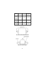
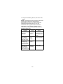
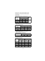
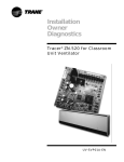
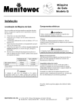
HOW TO READ A MODEL NUMBER
9 REMOTE AIR-COOLED
# CUBE SIZE
CONDENSER TYPE
0
1
2
3
4
5
AIR-COOLED
WATER-COOLED
AIR-COOLED
WATER-COOLED
AIR-COOLED
WATER-COOLED
REGULAR
REGULAR
DICE
DICE
HALF-DICE
HALF-DICE
Q R 0450 A
ICE MACHINE
MODEL
ICE CUBE SIZE
R REGULAR
D DICE
Y HALF DICE
ICE MACHINE
SERIES
CONDENSER TYPE
A SELF-CONTAINED AIR-COOLED
W SELF-CONTAINED WATER-COOLED
N REMOTE AIR-COOLED
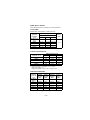
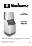
ICE CUBE SIZES
Regular
1-1/8" x 1-1/8" x 7/8"
2.86 x 2.86 x
2.22 cm
Dice
Half Dice
7/8" x 7/8" x 7/8" 3/8" x 1-1/8" x 7/8"
2.22 x 2.22 x
0.95 x 2.86 x
2.22 cm
2.22 cm
–1–
MODEL/SERIAL NUMBER LOCATION
These numbers are required when requesting
information from your local Manitowoc Distributor,
service representative, or Manitowoc Ice, Inc. The
model and serial number are listed on the OWNER
WARRANTY REGISTRATION CARD. They are also
listed on the MODEL/SERIAL NUMBER DECAL
affixed to the ice machine.
ICE MACHINE WARRANTY INFORMATION
Owner Warranty Registration Card
Warranty coverage begins the day the ice machine is
installed.
Important
Complete and mail the OWNER WARRANTY
REGISTRATION CARD as soon as possible to
validate the installation date.
If the OWNER WARRANTY REGISTRATION CARD is
not returned, Manitowoc will use the date of sale to the
Manitowoc Distributor as the first day of warranty
coverage for your new ice machine.
–2–
Warranty Coverage
GENERAL
The following Warranty outline is provided for your
convenience. For a detailed explanation, read the
warranty bond shipped with each product.
Contact your local Manitowoc representative or
Manitowoc Ice, Inc. if you need further warranty
information.
Important
This product is intended exclusively for commercial
application. No warranty is extended for personal,
family, or household purposes.
PARTS
1. Manitowoc warrants the ice machine against
defects in materials and workmanship, under
normal use and service for three (3) years from the
date of original installation.
2. The evaporator and compressor are covered by an
additional two (2) year (five years total) warranty
beginning on the date of the original installation.
LABOR
1. Labor required to repair or replace defective
components is covered for three (3) years from the
date of original installation.
2. The evaporator is covered by an additional
two (2) year (five years total) labor warranty
beginning on the date of the original installation.
EXCLUSIONS
The following items are not included in the ice
machine’s warranty coverage:
1. Normal maintenance, adjustments and cleaning as
outlined in this manual.
2. Repairs due to unauthorized modifications to the
ice machine or use of non-standard parts without
prior written approval from Manitowoc Ice, Inc.
–3–
3. Damage caused by improper installation of the ice
machine, electrical supply, water supply or
drainage, or damage caused by floods, storms, or
other acts of God.
4. Premium labor rates due to holidays, overtime, etc.;
travel time; flat rate service call charges; mileage
and miscellaneous tools and material charges not
listed on the payment schedule. Additional labor
charges resulting from the inaccessibility of
equipment are also excluded.
5. Parts or assemblies subjected to misuse, abuse,
neglect or accidents.
6. Damage or problems caused by installation,
cleaning and/or maintenance procedures
inconsistent with the technical instructions provided
in this manual.
This product is intended exclusively for commercial
application. No warranty is extended for personal,
family, or household purposes.
AUTHORIZED WARRANTY SERVICE
To comply with the provisions of the warranty, a
refrigeration service company qualified and authorized
by your Manitowoc Distributor, or a Contracted Service
Representative must perform the warranty repair.
NOTE: If the dealer you purchased the ice machine
from is not authorized to perform warranty service,
contact your Manitowoc Distributor or Manitowoc Ice,
Inc. for the name of the nearest authorized service
representative.
SERVICE CALLS
Normal maintenance, adjustments and cleaning as
outlined in this manual are not covered by the
warranty. If you have followed the procedures listed in
this manual, and the ice machine still does not perform
properly, call your Local Distributor or the Service
Department at Manitowoc Ice, Inc.
–4–
Installation
LOCATION OF ICE MACHINE
The location selected for the ice machine head section
must meet the following criteria. If any of these criteria
are not met, select another location.
• The location must be free of airborne and other
contaminants.
• The air temperature must be at least 35°F (1.6°C),
but must not exceed 110°F (43.4°C).
• The location must not be near heat-generating
equipment or in direct sunlight.
• The location must not obstruct air flow through or
around the ice machine. Refer to chart below for
clearance requirements.
• The ice machine must be protected if it will be
subjected to temperatures below 32°F (0°C). Failure
caused by exposure to freezing temperatures is not
covered by the warranty. See “Removal from
Service/Winterization”
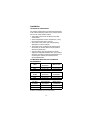
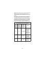
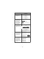
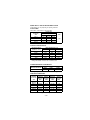
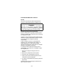
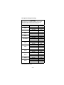
ICE MACHINE HEAD SECTION CLEARANCE
REQUIREMENTS
Q370
Self-Contained
Air-Cooled
Water-Cooled
Top/Sides
12" (30.5 cm)
5" (12.7 cm)
Back
5" (12.7 cm)
5" (12.7 cm)
Q1300 Q1600
Q1800
Self-Contained
Air-Cooled
Water-Cooled
and Remote
Top/Sides
24" (61 cm)
8" (20.3 cm)
Back
12" (30.5 cm)
5" (12.7 cm)
All other
Q models
Self-Contained
Air-Cooled
Water-Cooled
and Remote
Top/Sides
8" (20.3 cm)
5" (12.7 cm)
Back
5" (12.7 cm)
5" (12.7 cm)
Q1600 is not available as an air-cooled model.
–5–
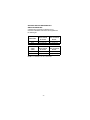
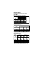
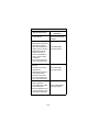
STACKING TWO ICE MACHINES ON A
SINGLE STORAGE BIN
A stacking kit is required for stacking two ice
machines. Installation instructions are supplied with
the stacking kit.
Q450/Q600/
Q800/Q1000
Stacked
Self-Contained
Air-Cooled
Stacked
Water-Cooled and
Remote
Top/Sides
16" (40.64 cm)
5" (12.70 cm)
Back
5" (12.70 cm)
5" (12.70 cm)
Q1300
Q1600
Q1800
Stacked
Self-Contained
Air-Cooled
Stacked
Water-Cooled and
Remote
Top/Sides
48" (121.92 cm)
24" (60.96 cm)
Back
12" (30.48 cm)
12" (30.48 cm)
Q1600 is not available as an air-cooled model.
–6–
Calculating Remote Condenser
Installation Distances
LINE SET LENGTH
The maximum length is 100' (30.5 m).
The ice machine compressor must have the proper oil
return. The receiver is designed to hold a charge
sufficient to operate the ice machine in ambient
temperatures between -20°F (-28.9°C) and 120°F
(49°C), with line set lengths of up to 100' (30.5 m).
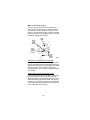
LINE SET RISE/DROP
The maximum rise is 35' (10.7 m).
The maximum drop is 15' (4.5 m).
! Caution
If a line set has a rise followed by a drop, another
rise cannot be made. Likewise, if a line set has a
drop followed by a rise, another drop cannot be
made.
–7–
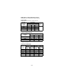
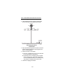
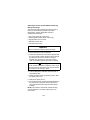
CALCULATED LINE SET DISTANCE
The maximum calculated distance is 150' (45.7 m).
Line set rises, drops, horizontal runs (or combinations
of these) in excess of the stated maximums will
exceed compressor start-up and design limits. This will
cause poor oil return to the compressor.
Make the following calculations to make sure the line
set layout is within specifications.
1. Insert the measured rise into the formula below.
Multiply by 1.7 to get the calculated rise.
(Example: A condenser located 10 feet above the
ice machine has a calculated rise of 17 feet.)
2. Insert the measured drop into the formula below.
Multiply by 6.6 to get the calculated drop.
(Example. A condenser located 10 feet below the
ice machine has a calculated drop of 66 feet.)
3. Insert the measured horizontal distance into the
formula below. No calculation is necessary.
4. Add together the calculated rise, calculated drop,
and horizontal distance to get the total
calculated distance. If this total exceeds 150'
(45.7 m), move the condenser to a new location
and perform the calculations again.
MAXIMUM LINE SET DISTANCE FORMULA
Step 1.
Measured Rise ____ X 1.7 = ______Calculated Rise
(35 ft. Max)
Step 2.
Measured Drop ____ X 6.6 = ______Calculated Drop
(15 ft. Max.)
Step 3.
Measured Horizontal Distance = _________Horizontal
(100 ft. Max.)
Distance
Step 4.
Total Calculated Distance = ________Total Calculated
(150 ft. Max.)
Distance
–8–
THIS PAGE INTENTIONALLY LEFT BLANK
–9–
THIS PAGE INTENTIONALLY LEFT BLANK
–10–
Removal from Service/Winterization
GENERAL
Special precautions must be taken if the ice machine is
to be removed from service for an extended period of
time or exposed to ambient temperatures of 32°F
(0°C) or below.
! Caution
If water is allowed to remain in the ice machine in
freezing temperatures, severe damage to some
components could result. Damage of this nature is
not covered by the warranty.
Follow the applicable procedure below.
SELF-CONTAINED AIR-COOLED ICE MACHINES
1. Disconnect the electric power at the circuit breaker
or the electric service switch.
2. Turn off the water supply.
3. Remove the water from the water trough.
4. Disconnect and drain the incoming ice-making
water line at the rear of the ice machine.
5. Blow compressed air in both the incoming water
and the drain openings in the rear of the ice
machine until no more water comes out of the inlet
water lines or the drain.
6. Make sure water is not trapped in any of the water
lines, drain lines, distribution tubes, etc.
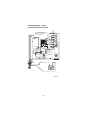
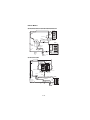
WATER-COOLED ICE MACHINES
1. Perform steps 1-6 under “Self-Contained AirCooled Ice Machines.”
2. Disconnect the incoming water and drain lines from
the water-cooled condenser.
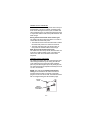
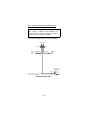
–11–
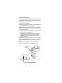
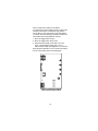
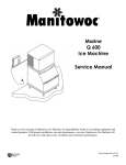
3. Insert a large screwdriver between the bottom
spring coils of the water regulating valve. Pry
upward to open the valve.
SV1624
4. Hold the valve open and blow compressed air
through the condenser until no water remains.
REMOTE ICE MACHINES
1. Move the ICE/OFF/CLEAN switch to OFF.
2. “Frontseat” (shut off) the receiver service valves.
Hang a tag on the switch as a reminder to open the
valves before restarting.
3. Perform steps 1-6 under “Self-Contained AirCooled Ice Machines.”
AUCS® ACCESSORY
Refer to the AuCS® Accessory manual for
winterization of the AuCS® Accessory.
–12–
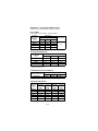
Ice Making Sequence of Operation
SELF-CONTAINED AIR- AND WATER-COOLED
Initial Start-Up or Start-Up After
Automatic Shut-Off
1. Water Purge
Before the compressor starts, the water pump and
water dump solenoid are energized for 45 seconds to
purge the ice machine of old water. This ensures that
the ice-making cycle starts with fresh water.
The harvest valve(s) is also energized during the
water purge, although it stays on for an additional 5
seconds (50-second total on time) during the initial
refrigeration system start-up.
2. Refrigeration System Start-Up
The compressor starts after the 45 second water
purge, and it remains on throughout the entire Freeze
and Harvest Sequences. The water fill valve is
energized at the same time as the compressor. It
remains on until the water level sensor closes for 3
continuous seconds, or until a six-minute time period
has expired. The harvest valve(s) remains on for 5
seconds during initial compressor start-up and then
shuts off.
At the same time the compressor starts, the
condenser fan motor (air-cooled models) is supplied
with power throughout the entire Freeze and Harvest
Sequences. The fan motor is wired through a fan cycle
pressure control, therefore it may cycle on and off.
(The compressor and condenser fan motor are wired
through the contactor. As a result, anytime the
contactor coil is energized, the compressor and fan
motor are supplied with power.)
–13–
Freeze Sequence
3. Prechill
The compressor is on for 30 seconds prior to water
flow to prechill the evaporator.
4. Freeze
The water pump restarts after the 30-second prechill.
An even flow of water is directed across the
evaporator and into each cube cell, where it freezes.
The water fill valve will cycle on, then off one more
time to refill the water trough.
When sufficient ice has formed, the water flow (not the
ice) contacts the ice thickness probe. After
approximately 7 seconds of continual water contact,
the Harvest sequence is initiated. The ice machine
cannot initiate a Harvest sequence until a 6-minute
freeze lock has been surpassed.
–14–
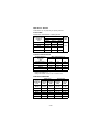
Harvest Sequence
5. Water Purge
The water pump continues to run, and the water dump
valve energizes for 45 seconds to purge the water in
the sump trough. The water fill valve energizes (turns
on) and de-energizes (turns off) strictly by time. The
water fill valve energizes for the last 15 seconds of the
45-second water purge. The water purge must be at
the factory setting of 45 seconds for the fill valve to
energize during the last 15 seconds of the Water
Purge. If set at less than 45 seconds the water fill
valve does not energize during the water purge.
After the 45 second water purge, the water fill valve,
water pump and dump valve de-energize. (Refer to
“Water Purge Adjustment” for details.) The harvest
valve also opens at the beginning of the water purge to
divert hot refrigerant gas into the evaporator.
6. Harvest
The harvest valve(s) remains open and the refrigerant
gas warms the evaporator causing the cubes to slide,
as a sheet, off the evaporator and into the storage bin.
The sliding sheet of cubes swings the water curtain
out, opening the bin switch. The momentary opening
and re-closing of the bin switch terminates the harvest
sequence and returns the ice machine to the freeze
sequence (Step 3 - 4.)
–15–
Automatic Shut-Off
7. Automatic Shut-Off
When the storage bin is full at the end of a harvest
sequence, the sheet of cubes fails to clear the water
curtain and will hold it open. After the water curtain is
held open for 7 seconds, the ice machine shuts off.
The ice machine remains off for 3 minutes before it
can automatically restart.
The ice machine remains off until enough ice has been
removed from the storage bin to allow the ice to fall
clear of the water curtain. As the water curtain swings
back to the operating position, the bin switch re-closes
and the ice machine restarts (steps 1 - 2), provided the
3 minute delay period is complete.
–16–
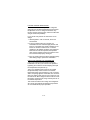
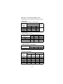
–17–
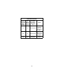
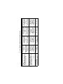
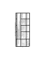
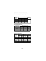
4. Freeze
3. Prechill
Freeze Sequence
2. Refrigeration
System Start-up
1. Water Purge
Initial Start-Up
Ice Making
Sequence of
Operation
On
Off
Off
On
1
Water
Pump
On/Off
one more
time
On then Off
Cycles
during first
45 sec.
May Cycle
On
Off
2
Water Fill
Valve
Off
Off
On
On
3
Harvest
Valve
Off
Off
Off
On
4
Water
Dump
Valve
On
On
On
Off
5
Contactor
Coil
Energized Parts Chart
Control Board Relays
On
On
On
Off
On/Off
May Cycle
On/Off
May Cycle
On/Off
May Cycle
Off
5B
Condenser
Fan Motor
Contactor
5A
Compressor
Unit 7 Sec.
Water Contact
w/Ice Thickness Probe
30 Seconds
5 Seconds
45 Seconds
Length
of Time
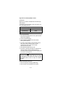
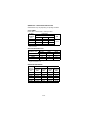
–18–
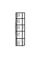
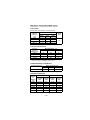
Off
Off
7. Automatic
Shut-Off
On
1
Water
Pump
6. Harvest
5. Water Purge
Harvest Sequence
Ice Making
Sequence of
Operation
Off
Off
Off
On
15 sec.
30 sec.
2
Water Fill
Valve
Off
On
On
3
Harvest
Valve
Off
Off
On
4
Water
Dump
Valve
Off
On
On
5
Contactor
Coil
Off
On
On
Off
On/Off
May Cycle
On/Off
May Cycle
5B
Condenser
Fan Motor
Contactor
5A
Compressor
Energized Parts Chart (Continued)
Control Board Relays
Until Bin Switch
Re-closes
Bin Switch
Activation
Factory
Set at
45 Seconds
Length
of Time
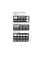
REMOTE
Initial Start-Up or Start-Up After
Automatic Shut-Off
1. Water Purge
Before the compressor starts, the water pump and
water dump solenoid are energized for 45 seconds, to
completely purge the ice machine of old water. This
feature ensures that the ice making cycle starts with
fresh water.
The harvest valve and harvest pressure regulating
(HPR) solenoid valves also energize during water
purge, although they stay on for an additional 5
seconds (50 seconds total on time) during the initial
refrigeration system start-up.
2. Refrigeration System Start-Up
The compressor and liquid line solenoid valve
energize after the 45 second water purge and remain
on throughout the entire Freeze and Harvest
Sequences. The water fill valve is energized at the
same time as the compressor. It remains on until the
water level sensor closes for 3 continuous seconds, or
until a six-minute time period has expired. The harvest
valve and HPR solenoid valves remain on for 5
seconds during initial compressor start-up and then
shut off.
The remote condenser fan motor starts at the same
time the compressor starts and remains on throughout
the entire Freeze and Harvest Sequences.
–19–
Freeze Sequence
3. Prechill
The compressor is on for 30 seconds prior to water
flow, to prechill the evaporator.
4. Freeze
The water pump restarts after the 30 second prechill.
An even flow of water is directed across the
evaporator and into each cube cell, where it freezes.
The water fill valve will cycle on and then off one more
time to refill the water trough.
When sufficient ice has formed, the water flow (not the
ice) contacts the ice thickness probe. After
approximately 7 seconds of continual water contact,
the harvest sequence is initiated. The ice machine
cannot initiate a harvest sequence until a 6 minute
freeze lock has been surpassed.
–20–
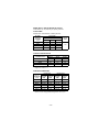
Harvest Sequence
5. Water Purge
The water pump continues to run, and the water dump
valve energizes for 45 seconds to purge the water in
the sump trough. The water fill valve energizes (turns
on) and de-energizes (turns off) strictly by time. The
water fill valve energizes for the last 15 seconds of the
45-second water purge. The water purge must be at
the factory setting of 45 seconds for the fill valve to
energize during the last 15 seconds of the Water
Purge. If set at less than 45 seconds the water fill
valve does not energize during the water purge.
After the 45 second water purge, the water fill valve,
water pump and dump valve de-energize. (Refer to
“Water Purge Adjustment”) The harvest valve(s) and
HPR solenoid valve also open at the beginning of the
water purge.
6. Harvest
The HPR valve and the harvest valve(s) remain open
and the refrigerant gas warms the evaporator causing
the cubes to slide, as a sheet, off the evaporator and
into the storage bin. The sliding sheet of cubes swings
the water curtain out, opening the bin switch. The
momentary opening and re-closing of the bin switch
terminates the harvest sequence and returns the ice
machine to the freeze sequence (Step 3 - 4.)
Automatic Shut-Off
7. Automatic Shut-Off
When the storage bin is full at the end of a harvest
sequence, the sheet of cubes fails to clear the water
curtain and will hold it open. After the water curtain is
held open for 7 seconds, the ice machine shuts off.
The ice machine remains off for 3 minutes before it
can automatically restart.
The ice machine remains off until enough ice has been
removed from the storage bin to allow the ice to drop
clear of the water curtain. As the water curtain swings
back to the operating position, the bin switch re-closes
and the ice machine restarts (steps 1 - 2) provided the
3 minute delay period is complete.
–21–
–22–
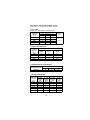
4. Freeze
3. Prechill
Freeze Sequence
2. Refrigeration
System Start-up
1. Water Purge
Initial Start-Up
Ice Making
Sequence of
Operation
On
Off
Off
On
1
Water
Pump
On/Off
one more
time
On then Off
Cycles
during first
45 sec.
May Cycle
On
Off
2
Water Fill
Valve
Off
Off
On
On
3
a. Harvest
Valve(s)
b. HPR
Solenoid
Off
Off
Off
On
4
Water
Dump
Valve
On
On
On
Off
5
a. Contactor
Coil
b. Liquid Line
Solenoid
Remote Energized Parts Chart
Control Board Relays
On
On
On
Off
On
On
On
Off
5B
Condenser
Fan Motor
Contactor
5A
Compressor
Unit 7 Sec.
Water Contact
w/Ice Thickness
Probe
30 Seconds
5 Seconds
45 Seconds
Length
of Time
–23–
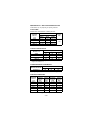
Off
Off
7. Automatic
Shut-Off
On
1
Water
Pump
6. Harvest
5. Water Purge
Harvest Sequence
Ice Making
Sequence of
Operation
Off
Off
On
15 sec.
Off
30 sec.
2
Water Fill
Valve
Off
On
On
3
a. Harvest
Valve(s)
b. HPR
Solenoid
Off
Off
On
4
Water
Dump
Valve
Control Board Relays
Off
On
On
5
a. Contactor
Coil
b. Liquid Line
Solenoid
Off
On
On
Off
On
On
5B
Condenser
Fan Motor
Contactor
5A
Compressor
Remote Energized Parts Chart (Continued)
Until Bin
Switch
Recloses
Bin Switch
Activation
Factory
Set at
45 Seconds
Length
of Time
THIS PAGE INTENTIONALLY LEFT BLANK
–24–
Electrical System
WIRING DIAGRAMS
The following pages contain electrical wiring diagrams.
Be sure you are referring to the correct diagram for the
ice machine which you are servicing.
! Warning
Always disconnect power before working on
electrical circuitry.
Wiring Diagram Legend
The following symbols are used on all of the wiring
diagrams:
*
Internal Compressor Overload
(Some models have external
compressor overloads)
**
Fan Motor Run Capacitor
(Some models do not incorporate fan
motor run capacitor)
TB
Terminal Board Connection
(Terminal board numbers are printed
on the actual terminal board)
( )
Wire Number Designation
(The number is marked at each end of
the wire)
—>>—
Multi-Pin Connection
(Electrical Box Side) —>>—
(Compressor Compartment Side)
–25–
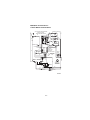
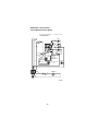
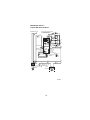
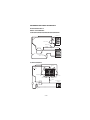
Q200/Q280/Q320 - Self Contained 1 Phase With Terminal Board
L1
TB35
CAUTION: DISCONNECT POWER BEFORE WORKING
ON ELECTRICAL CIRCUITRY.
DIAGRAM SHOWN DURING FREEZE CYCLE
SEE SERIAL PLATE FOR VOLTAGE
(55)
TB32
WATER
VALVE
(20)
(61)
(21)
(60)
HARVEST
SOLENOID
2
(77)
4
1
HIGH PRES
CUTOUT
(57)
TB31
1C
(56)
(74)
CONTACTOR
COIL
CLEAN LIGHT
1G LOW D.C.
VOLTAGE
PLUG
TB30
TB30
WATER LEVEL LIGHT
BIN SWITCH LIGHT
(62)
BIN SWITCH
(64)
(63)
HARVEST LIGHT/
SAFETY LIMIT CODE LIGHT
TOGGLE SWITCH
VIEW FOR WIRING
(68) ICE
68
(67)
(69)
INTERNAL WORKING
OFF
66
67
VIEW
(66)
62
69
(62) CLEAN
(65)
(66)
(49)
COMPRESSOR
(47)
S
R
*OVERLOAD C
CONTACTOR
CONTACTS
(48)
(42)
L1
(51)
TB33
TB30
TERMINATES AT
PIN CONNECTION
(73)
1F
NOT USED
(99)
TB30
(58)
TB37 (59)
WATER LEVEL PROBE
(75)
(81)
(76)
WATER
PUMP
(98)
FUSE (7A)
ICE THICKNESS PROBE
(80)
DUMP
SOLENOID
3
5
TRANS.
TB35
L2 (N)
(22)
TB30
(50)
TB30
PTCR
(52)
(85)
(86)
(53)
TB34
FAN CYCLE CONTROL
FAN MOTOR
(AIR COOLED ONLY)
RUN CAPACITOR**
SV1654
–26–
TB30
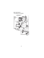
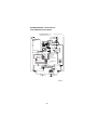
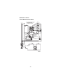
Q280/Q370 - Self Contained 1 Phase Without Terminal Board
SEE SERIAL PLATE FOR VOLTAGE
CAUTION: DISCONNECT POWER BEFORE WORKING
ON ELECTRICAL CIRCUITRY.
DIAGRAM SHOWN DURING FREEZE CYCLE
(89)
(55)
(20)
(21)
(61)
WATER
VALVE
(77)
3
(60)
4
2
HIGH PRES
CUTOUT
HARVEST
SOLENOID
(98)
(57)
TRANS.
FUSE (7A)
CLEAN LIGHT
1G LOW D.C.
VOLTAGE
PLUG
(74)
WATER LEVEL
BIN SWITCH LIGHT
(62)
(64)
CONTACTOR
COIL
(56)
1F
NOT USED
BIN SWITCH
TERMINATES AT
PIN CONNECTION
1C
WATER LEVEL PROBE
(99)
WATER
PUMP
(58)
(59)
(42)
(75)
(81)
DUMP
SOLENOID
5
ICE THICKNESS PROBE
(80)
(76)
1
(88)
L2 (N)
(22)
(63)
HARVEST LIGHT/
SAFETY LIMIT CODE LIGHT
(65)
(68)
(69)
(67)
(66)
ICE
VIEW FOR
WIRING
68
TOGGLE SWITCH
INTERNAL WORKING
VIEW
OFF
66
62
CLEAN
(62)
67
69
COMPRESSOR
CONTACTOR
CONTACTS
R
OVERLOAD INTERNAL C
{230V 50/60 HZ}
S
R
C
(49)
L1
(48)
(46)
(51)
S
(47)
POTENTIAL
RELAY
5
4
2
(44)
1
(45)
START
CAPACITOR
COMPRESSOR
TERMINAL LAYOUT
VIEWED FROM END
OF COMPRESSOR
(50)
(85)
(86)
FAN CYCLE CONTROL
FAN MOTOR
(AIR COOLED ONLY)
RUN CAPACITOR**
SV3018
–27–
SHUNT ON
CONTACTOR
L1
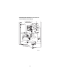
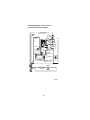
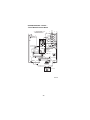
Q320 - Self Contained 1 Phase Without Terminal Board
CAUTION: DISCONNECT POWER BEFORE WORKING
ON ELECTRICAL CIRCUITRY.
WATER
VALVE
DIAGRAM SHOWN DURING FREEZE CYCLE
SEE SERIAL PLATE FOR VOLTAGE
L1
(61)
(55)
(89)
(88)
HARVEST
SOLENOID
3
3
(77)
4
2
1
5
HIGH PRES
CUTOUT
(57)
(59)
(64)
(56)
1F
HARVEST LIGHT/
SAFETY LIMIT CODE LIGHT
(63)
TOGGLE SWITCH
(67)
(68)
(69)
(62)
*OVERLOAD
INTERNAL WORKING
VIEW
CLEAN
(49)
66
62
67
69
(47)
S
C
(50)
PTCR
(48)
(51)
VIEW FOR WIRING
68
ICE
OFF
COMPRESSOR
R
L1
(74)
WATER LEVEL
BIN SWITCH LIGHT
(66)
(42)
CONTACTOR
COIL
CLEAN LIGHT
1G LOW D.C.
VOLTAGE
PLUG
(65)
CONTACTOR
CONTACTS
TERMINATES AT
PIN CONNECTION
(58)
(62)
BIN SWITCH
(81)
(99)
WATER
PUMP
(98)
FUSE (7A)
NOT USED
(75)
(76)
DUMP
SOLENOID
1C
WATER LEVEL PROBE
(80)
(60)
TRANS.
ICE THICKNESS PROBE
L2 (N)
(22)
(20)
(85)
(86)
FAN MOTOR
(AIR COOLED ONLY)
FAN CYCLE CONTROL
RUN CAPACITOR**
COMPRESSOR
(49)
(47)
OVERLOAD
RUN CAPACITOR
R
R
(50)
(46)
(48)
(45)
PTCR
SV2070
–28–
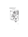
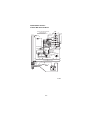
Q420/Q450/Q600/Q800/Q1000 - Self Contained1 Phase With Terminal Board
CAUTION: DISCONNECT POWER BEFORE WORKING
ON ELECTRICAL CIRCUITRY.
DIAGRAM SHOWN DURING FREEZE CYCLE
L1
L2 (N)
(20)
(55)
TB32
B35
SEE SERIAL PLATE FOR VOLTAGE
HIGH PRES
CUTOUT
WATER
VALVE
(77)
2
HARVEST
SOLENOID
4
1
3
5
WATER
PUMP
(59)
(73)
1C
(56)
(42)
TB30
HARVEST LIGHT/
SAFETY LIMIT CODE LIGHT
TOGGLE SWITCH
VIEW FOR WIRING
(68) ICE
68
(67)
(69)
INTERNAL WORKING
66
OFF
67
VIEW
62
69
(62) CLEAN
(66)
B35
TB30
BIN SWITCH LIGHT
(65)
(49)
COMPRESSOR
(47)
S
R
CONTACTOR
CONTACTS
CONTACTOR
COIL
TB30
WATER LEVEL LIGHT
(63)
(64)
TERMINATES AT
PIN CONNECTION
(74)
TB30
CLEAN LIGHT
(62)
BIN SWITCH
(99)
(58)
1F
LOW D.C.
1G VOLTAGE
PLUG
(81)
(98)
TB31
TB37
NOT USED
(75)
DUMP
SOLENOID
(57)
FUSE (7A)
WATER LEVEL PROBE
(80)
(76)
TRANS.
ICE THICKNESS PROBE
(22)
(21)
(61)
(60)
*OVERLOAD C
RUN CAPACITOR
R
R
(50)
(46)
TB30
(48)
L1
(51)
TB33
(52)
(85)
(86)
(53) TB34
(45)
PTCR
FAN MOTOR
(AIR COOLED ONLY)
FAN CYCLE CONTROL
TB30
RUN CAPACITOR**
SV1646
–29–
Q420/Q450/Q600/Q800/Q1000 - Self Contained1 Phase Without Terminal Board
CAUTION: DISCONNECT POWER BEFORE WORKING
ON ELECTRICAL CIRCUITRY.
DIAGRAM SHOWN DURING FREEZE CYCLE
L1
SEE SERIAL PLATE FOR VOLTAGE
(20)
(55)
(89)
L2 (N)
WATER
VALVE
(22)
(21)
(61)
HARVEST
SOLENOID
HIGH PRES
CUTOUT
(77)
3
(88)
(60)
4
2
1
5
(76)
TRANS.
(80)
DUMP
SOLENOID
WATER
PUMP
(98)
(57)
(75)
(81)
(99)
FUSE (7A)
(59)
ICE THICKNESS PROBE
1C
WATER LEVEL PROBE
1F
1G
CLEAN LIGHT
(63)
(65)
HARVEST LIGHT/
SAFETY LIMIT CODE LIGHT
TOGGLE SWITCH
(67)
(68)
(69)
(62)
ICE
OFF
(66)
S
R
(49)
VIEW FOR WIRING
68
66
67
62
69
(49)
RUN
CAPACITOR
(47)
(42)
*OVERLOAD
INTERNAL WORKING
VIEW
CLEAN
COMPRESSOR
CONTACTOR
CONTACTS
(74)
WATER LEVEL
BIN SWITCH LIGHT
(62)
(64)
CONTACTOR
COIL
(56)
LOW D.C.
VOLTAGE
PLUG
NOT USED
BIN SWITCH
TERMINATES AT
PIN CONNECTION
(58)
(46)
(50)
C
(48)
L1
(45)
(51)
(85)
PTCR
(86)
FAN CYCLE CONTROL
FAN MOTOR
(AIR COOLED ONLY)
RUN CAPACITOR**
SV2071
–30–
Q800/Q1000 - Self Contained 3 Phase With Terminal Board
SEE SERIAL PLATE FOR VOLTAGE CAUTION: DISCONNECT POWER BEFORE WORKING
ON ELECTRICAL CIRCUITRY.
DIAGRAM SHOWN DURING FREEZE CYCLE
L3 L2 L1
WATER
VALVE
(61)
(60)
HIGH PRES
CUTOUT
(55)
(77)
2
4
1
3
5
(57)
FUSE (7A)
(58)
(56)
(66)
(99)
WATER
PUMP
TERMINATES AT
PIN CONNECTION
(74)
CONTACTOR
COIL
TB30
TB30
TB30
TB30
WATER LEVEL LIGHT
(62)
(63)
(75)
CLEAN LIGHT
LOW D.C.
1G VOLTAGE
PLUG
(64) BIN SWITCH (65)
(81)
(73)
1F
NOT USED
(80)
(76)
DUMP
SOLENOID
TB37 (59)
1C
WATER LEVEL PROBE
HARVEST
SOLENOID
TB31 (98)
TRANS.
ICE THICKNESS PROBE
(22)
(21)
(20)
TB32
TB35
BIN SWITCH LIGHT
HARVEST LIGHT/
SAFETY LIMIT CODE LIGHT
TOGGLE SWITCH
VIEW FOR WIRING
(68) ICE
68
(67)
(69)
INTERNAL WORKING
OFF
66
67
VIEW
(66)
62
69
(62) CLEAN
(96)
TB30
(42)
TB35
L3 L2 L1
TB33 (52)
(85)
(86)
(53)
FAN CYCLE CONTROL
T2 COMPRESSOR
TB34
FAN MOTOR
(AIR COOLED ONLY)
RUN CAPACITOR**
T3 T1
–31–
SV1647a
TB30
Q800/Q1000 - Self Contained 3 Phase Without Terminal Board
CAUTION: DISCONNECT POWER BEFORE WORKING
ON ELECTRICAL CIRCUITRY.
DIAGRAM SHOWN DURING FREEZE CYCLE
SEE SERIAL PLATE FOR VOLTAGE
L3 L2 L1
WATER
VALVE
(20)
(89)
(55)
(61)
(88)
(22)
(21)
HIGH PRES
CUTOUT
HARVEST
SOLENOID
(77)
3
(80)
(60)
4
2
1
5
DUMP
SOLENOID
WATER
PUMP
(98)
(99)
FUSE (7A)
(59)
ICE THICKNESS PROBE
NOT USED
(56)
LOW D.C.
VOLTAGE
PLUG
BIN SWITCH
(64)
CONTACTOR
COIL
(74)
CLEAN LIGHT
WATER LEVEL
BIN SWITCH LIGHT
HARVEST LIGHT/
SAFETY LIMIT CODE LIGHT
(62)
(42)
TERMINATES AT
PIN CONNECTION
(58)
1C
1F
1G
WATER LEVEL PROBE
(75)
(81)
(76)
(57)
TRANS.
(63)
(65)
(67)
(66)
TOGGLE SWITCH
(68) ICE
(69)
OFF
(62)
INTERNAL WORKING
VIEW
CLEAN
VIEW FOR WIRING
68
66
67
62
69
L3 L2 L1
CONTACTOR
CONTACTS
(51)
T2
FAN MOTOR
(AIR COOLED ONLY)
(85)
(86)
FAN CYCLE CONTROL
RUN CAPACITOR**
T3
T1
SV2072
–32–
Q1300/Q1800 - Self Contained 1 Phase With Terminal Board
SEE SERIAL PLATE FOR VOLTAGE
L2(N)
WATER
VALVE
CAUTION: DISCONNECT POWER BEFORE WORKING
ON ELECTRICAL CIRCUITRY.
DIAGRAM SHOWN DURING FREEZE CYCLE
L1
(22)
(20)
(55)
TB32
TB35
(21)
RH HARVEST
SOLENOID
(61)
HIGH PRES
CUTOUT
(88)
(60)
LH HARVEST
SOLENOID
(58)
(73)
1F
(56)
BIN SWITCH
(81)
(99)
WATER
PUMP
TB30
TB30
TERMINATES AT
PIN CONNECTION
(74)
CONTACTOR
COIL
TB30
TB30
CLEAN LIGHT
1G LOW D.C.
VOLTAGE
PLUG
WATER LEVEL LIGHT
(62)
BIN SWITCH LIGHT
HARVEST LIGHT/
SAFETY LIMIT CODE LIGHT
(65)
TOGGLE SWITCH
VIEW FOR WIRING
(68)
ICE
68
(67)
(69)
INTERNAL WORKING
OFF
66
67
VIEW
(66)
62
69
(62) CLEAN
(66)
CRANKCASE HEATER
(95)
TB35
TB37 (59)
1C
(63)
(64)
(98)
TB31
FUSE (7A)
AUCS DISPENSE TIME
(75)
DUMP
SOLENOID
(57)
TRANS.
ICE THICKNESS PROBE
(80)
(76)
5
WATER LEVEL PROBE
(87)
(77)
2
4
1
3
(94)
TB30
(49)
COMPRESSOR
(47)
R
CONTACTOR
CONTACTS
TB35
*OVERLOAD
(42)
S
RUN CAPACITOR
R
(46)
L1
(50)
CONTACTOR
CONTACTS
(96)
(45)
L2
(51)
TB33
R
C
(48)
(52)
(85)
(53)
(86)
PTCR (44)
TB34
FAN CYCLE CONTROL
RUN CAPACITOR**
FAN MOTOR
(AIR COOLED ONLY)
SV1652
–33–
TB30
Q1300/Q1600/Q1800 - Self Contained 1 Phase Without Terminal Board
CAUTION: DISCONNECT POWER BEFORE WORKING
ON ELECTRICAL CIRCUITRY.
DIAGRAM SHOWN DURING FREEZE CYCLE
L1
SEE SERIAL PLATE FOR VOLTAGE
L2 (N)
(20)
(55)
(89)
(22)
(21)
WATER
VALVE
(61)
HIGH PRES
CUTOUT
3
4
2
1
5
(88)
(77)
HARVEST
SOLENOID
(60)
(76)
DUMP
SOLENOID
(42)
(98)
WATER
PUMP
(57)
TRANS.
FUSE (7A)
(59)
ICE THICKNESS PROBE
1C
1F
(64)
(99)
CONTACTOR
COIL
(56)
(74)
WATER LEVEL LIGHT
BIN SWITCH LIGHT
HARVEST LIGHT/
SAFETY LIMIT CODE LIGHT
(63)
(65)
TOGGLE SWITCH
(68)
ICE
(67)
(69)
OFF
(66)
(62)
VIEW FOR WIRING
68
INTERNAL WORKING
VIEW
CLEAN
CRANKCASE HEATER
(95)
COMPRESSOR
66
62
(94)
RUN CAPACITOR
(50)
(46)
C
(48)
(96)
(45)
L1
CONTACTOR
CONTACTS
L2
CONTACTOR
CONTACTS
PTCR
(85)
67
69
(49)
(47)
S
R
*OVERLOAD
(51)
(75)
TERMINATES AT
PIN CONNECTION
CLEAN LIGHT
1G LOW D.C.
VOLTAGE
PLUG
(62)
BIN SWITCH
(81)
(58)
WATER LEVEL PROBE
AUCS DISPENSE TIME
(80)
(86)
FAN MOTOR
(AIR COOLED ONLY)
FAN CYCLE CONTROL
RUN CAPACITOR**
SV2075
–34–
Q1300/Q1800 - Self Contained 3 Phase With Terminal Board
SEE SERIAL PLATE FOR VOLTAGE
CAUTION: DISCONNECT POWER BEFORE WORKING
ON ELECTRICAL CIRCUITRY.
DIAGRAM SHOWN DURING FREEZE CYCLE
(21)
L3 L2 L1
(20)
TB32
TB35
HIGH PRES
CUTOUT
(61)
(60)
2
4
1
3
5
(55)
TRANS.
FUSE (7A)
ICE THICKNESS PROBE
TB37(59)
TERMINATES AT
PIN CONNECTION
(74)
(73)
CONTACTOR
COIL
(56)
1F
(62)
(63)
CRANKCASE HEATER
(95)
(94)
(96)
(42)
TB35
NOTE: WIRE (96) IS NOT USED ON 50HZ
TB33 (52)
(85)
TB30
WATER LEVEL LIGHT
HARVEST LIGHT/
SAFETY LIMIT CODE LIGHT
TOGGLE SWITCH
VIEW FOR WIRING
(68) ICE
68
(67)
(69)
INTERNAL WORKING
OFF
66
67
VIEW
(66)
62
CLEAN
69
(62)
(66)
L3 L2 L1
TB30
BIN SWITCH LIGHT
(64) BIN SWITCH (65)
TB35
CLEAN LIGHT
1G LOW D.C.
VOLTAGE
PLUG
AUCS DISPENSE TIME
RH HARVEST
SOLENOID
(88)
(87)
N - 50HZ
(77)
ONLY
(80)
LH HARVEST
SOLENOID
(76)
(75)
TB30
(81)
DUMP
TB30
SOLENOID
(57)
TB31 (98)
(99)
TB30
WATER
PUMP
(58)
1C
WATER LEVEL PROBE
WATER
VALVE
(22)
(86)
(53)
TB34
FAN CYCLE CONTROL
T2 COMPRESSOR
FAN MOTOR
(AIR COOLED ONLY)
TB30
TB30
TB30
RUN CAPACITOR**
T3 T1
SV1653
–35–
Q1300/Q1600/Q1800 - Self Contained 3 Phase Without Terminal Board
SEE SERIAL PLATE FOR VOLTAGE
L3 L2 L1
(89)
CAUTION: DISCONNECT POWER BEFORE WORKING
ON ELECTRICAL CIRCUITRY.
DIAGRAM SHOWN DURING FREEZE CYCLE
(20)
(55)
(61)
HIGH PRES
(88) CUTOUT
3
4
2
1
5
(42)
(60)
LH HARVEST
SOLENOID
(76)
DUMP
SOLENOID
FUSE (7A)
(98)
WATER
PUMP
(59)
ICE THICKNESS PROBE
(56)
1F
AUCS DISPENSE TIME
LOW D.C.
VOLTAGE
PLUG
1G
(63)
(64)
(65)
N - 50HZ
ONLY
(80)
(75)
(81)
(99)
TERMINATES AT
PIN CONNECTION
CONTACTOR
COIL
CLEAN LIGHT
WATER LEVEL LIGHT
BIN SWITCH LIGHT
(62)
BIN SWITCH
(87)
(58)
1C
WATER LEVEL PROBE
(22)
RH HARVEST
SOLENOID
(88)
(77)
(57)
TRANS.
WATER
VALVE
(21)
HARVEST LIGHT/
SAFETY LIMIT CODE LIGHT
TOGGLE SWITCH
(68)
ICE
(67)
(69)
INTERNAL WORKING
OFF
(66)
VIEW
(62)
CLEAN
(95)
VIEW FOR WIRING
68
66
62
67
69
(94)
CRANKCASE HEATER
NOTE: WIRE (96) IS NOT USED ON 50HZ (96)
L3
L2 L1
FAN MOTOR
(AIR COOLED ONLY)
(51)
T2
(85)
(86)
FAN CYCLE CONTROL
RUN CAPACITOR**
T1
T3
COMPRESSOR
SV3008
–36–
Q450/Q600/Q800/Q1000 - Remote 1 Phase With Terminal Board
CAUTION: DISCONNECT POWER BEFORE WORKING
ON ELECTRICAL CIRCUITRY.
DIAGRAM SHOWN DURING FREEZE CYCLE
L1
SEE SERIAL PLATE FOR VOLTAGE
L2 (N)
(21)
(22)
WATER
VALVE
HPR
SOLENOID
(20)
TB32
TB35
(55)
(61)
(60)
HIGH PRES
CUTOUT
(78)
2
4
1
3
5
(58)
(59)
(73)
1C
(56)
1F
CLEAN LIGHT
1G LOW D.C.
VOLTAGE
PLUG
BIN SWITCH
(64)
WATER LEVEL LIGHT
BIN SWITCH LIGHT
HARVEST LIGHT/
SAFETY LIMIT CODE LIGHT
(67)
(66)
TB30
(82)
LIQUID LINE
SOLENOID
(74)
TB30
CONTACTOR
COIL
TB30
(63)
(65)
TB30
(83)
(62)
(66)
(81)
(99)
WATER
PUMP
(98)
TB37
NOT USED
(75)
DUMP
SOLENOID
(57)
TB31
FUSE (7A)
WATER LEVEL PROBE
(80)
(76)
TRANS.
ICE THICKNESS PROBE
(79)
(77)
HARVEST
SOLENOID
TOGGLE SWITCH
VIEW FOR WIRING
(68) ICE
68
(69)
INTERNAL WORKING
OFF
66
67
VIEW
62
(62) CLEAN
69
(49)
COMPRESSOR
(47)
R
CONTACTOR
CONTACTS
TB35
*OVERLOAD
S
RUN CAPACITOR
R
R
(46)
(48)
(42)
L1
(52)
TB30
(45)
(51)
TB33
(50)
C
TERMINATES AT
PIN CONNECTION
(53)
PTCR
TB34
(F2)
(F1)
TB30
REMOTE
FAN MOTOR
REMOTE CONDENSER
RUN CAPACITOR
SV1648
–37–
Q450/Q600/Q800/Q1000 - Remote 1 Phase Without Terminal Board
CAUTION: DISCONNECT POWER BEFORE WORKING
ON ELECTRICAL CIRCUITRY.
DIAGRAM SHOWN DURING FREEZE CYCLE
L1
SEE SERIAL PLATE FOR VOLTAGE
(20)
(89)
(55)
(21)
HPR
SOLENOID
(61)
(78)
HIGH PRES
CUTOUT
(22)
WATER
VALVE
L2 (N)
(79)
2
(88)
(88)
HARVEST
SOLENOID
(60)
4
1
3
5
(77)
DUMP
SOLENOID
(57)
TRANS.
(98)
FUSE (7A)
(59)
LOW D.C.
VOLTAGE
PLUG
1G
AUCS DISPENSE TIME
(63)
(64)
(65)
(42)
CONTACTOR
COIL
(74)
WATER LEVEL LIGHT
HARVEST LIGHT/
SAFETY LIMIT CODE LIGHT
TOGGLE SWITCH
(68)
ICE
(67)
(69)
WORKING
OFF INTERNAL
(66)
VIEW
(62) CLEAN
COMPRESSOR
(49)
R
(47)
*OVERLOAD
(82)
LIQUID LINE
SOLENOID
CLEAN LIGHT
S
R
R
VIEW FOR WIRING
68
66
67
62
69
(94)
RUN CAPACITOR
(46)
CONTACTOR
CONTACTS
(75)
BIN SWITCH LIGHT
(62)
BIN SWITCH
(83)
(56)
1F
WATER LEVEL PROBE
(81)
(99)
WATER
PUMP
(58)
1C
ICE THICKNESS PROBE
(80)
(50)
C
(48)
(45)
L1
PTCR
(51)
F1
F2
REMOTE
FAN MOTOR
REMOTE CONDENSER
RUN CAPACITOR**
SV2073
–38–
Q800/Q1000 -Remote 3 Phase With Terminal Board
SEE SERIAL PLATE FOR VOLTAGE
L3 L2 L1
CAUTION: DISCONNECT POWER BEFORE WORKING
ON ELECTRICAL CIRCUITRY.
(21)
DIAGRAM SHOWN DURING FREEZE CYCLE
(20)
HPR
SOLENOID
(61)
TB32
TB35
(60)
HIGH PRES
CUTOUT
(55)
(78)
TB31 (98)
FUSE (7A)
TB37 (59)
ICE THICKNESS PROBE
(73)
1C
(56)
HARVEST LIGHT/
SAFETY LIMIT CODE LIGHT
TB30
(F1)
(F2)
TB30
CONTACTOR
CONTACTS
TB33
(52)
TERMINATES AT (53)
PIN CONNECTION
TB34
REMOTE
FAN MOTOR
T2 COMPRESSOR
T3 T1
TB30
TOGGLE SWITCH
VIEW FOR WIRING
(68) ICE
68
(67)
(69)
INTERNAL WORKING
OFF
66
67
VIEW
(66)
62
69
(62) CLEAN
(96)
(42)
TB35
TB30
BIN SWITCH LIGHT
(63)
L3 L2 L1
TB30
WATER LEVEL LIGHT
(62)
(64) BIN SWITCH (65)
(82)
LIQUID LINE
SOLENOID
(74)
CONTACTOR
COIL
TB30
(83)
CLEAN LIGHT
LOW D.C.
1G VOLTAGE
PLUG
AUCS DISPENSE TIME
(75)
(99)
WATER
PUMP
(58)
1F
(80)
(76)
(81)
DUMP
SOLENOID
(57)
TRANS.
WATER LEVEL PROBE
(79)
(77)
HARVEST
SOLENOID
2
4
1
3
5
(22)
WATER
VALVE
REMOTE CONDENSER
RUN CAPACITOR
SV1649
–39–
Q800/Q1000 - Remote 3 Phase Without Terminal Board
CAUTION: DISCONNECT POWER BEFORE WORKING
ON ELECTRICAL CIRCUITRY.
DIAGRAM SHOWN DURING FREEZE CYCLE
SEE SERIAL PLATE FOR VOLTAGE
(20)
L3 L2 L1
(88)
(61)
(89)
HIGH PRES
CUTOUT
(55)
(60)
FUSE (7A)
1F
1G LOW D.C.
VOLTAGE
PLUG
NOT USED
(64)
(81)
(98)
WATER
PUMP
(99)
(59)
(82)
LIQUID LINE
SOLENOID
(83)
CONTACTOR
(56)
COIL
CLEAN LIGHT
(74)
WATER LEVEL LIGHT
BIN SWITCH LIGHT
(62)
BIN SWITCH
(80)
(58)
1C
WATER LEVEL PROBE
(79)
(77)
HARVEST
SOLENOID
(76)
DUMP
SOLENOID
(57)
(22)
HPR
SOLENOID
(78)
3
4
2
1
5
TRANS.
ICE THICKNESS PROBE
WATER
VALVE
(21)
(63)
(65)
(42)
(66)
(68)
HARVEST LIGHT/
SAFETY LIMIT CODE LIGHT
TOGGLE SWITCH
ICE
(67)
(69)
INTERNAL WORKING
OFF
VIEW
CLEAN
(62)
VIEW
FOR
WIRING
68
66
67
62
69
(75)
L3 L2 L1
(F1)
(F2)
CONTACTOR
CONTACTS
(85)
(51)
T2
REMOTE
FAN MOTOR
T1
T3
COMPRESSOR
RUN CAPACITOR
REMOTE CONDENSER
SV2074
–40–
Q1300/Q1800 - Remote 1 Phase With Terminal Board
CAUTION: DISCONNECT POWER BEFORE WORKING
ON ELECTRICAL CIRCUITRY.
DIAGRAM SHOWN DURING FREEZE CYCLE
SEE SERIAL PLATE FOR VOLTAGE
WATER
L2 (N)
VALVE
(22)
(21)
HPR
SOLENOID
(78)
L1
(20)
(61)
HIGH PRES
CUTOUT
(77)
LH HARVEST
SOLENOID
TB31
(58)
(56)
WATER LEVEL LIGHT
HARVEST LIGHT/
SAFETY LIMIT CODE LIGHT
VIEW FOR WIRING
TOGGLE SWITCH
(68) ICE
68
(67)
(69)
INTERNAL WORKING
OFF
66
67
VIEW
(66)
62
69
(62) CLEAN
(64) BIN SWITCH (65)
(66)
CRANKCASE HEATER
(95)
(49)
COMPRESSOR
(47)
S
R
*OVERLOAD
(94)
RUN CAPACITOR
R
R
(46)
C
(48)
L1
(45)
(51)
TB33
(52)
TB30
(82)
LIQUID LINE
SOLENOID
(74)
TB30
CONTACTOR
COIL
TB30
BIN SWITCH LIGHT
(63)
CONTACTOR
CONTACTS
TB30
CLEAN LIGHT
1G LOW D.C.
VOLTAGE
PLUG
(62)
(42)
(99)
WATER
PUMP
(83)
(73)
1C
AUCS DISPENSE TIME
(98)
TB37 (59)
1F
WATER LEVEL PROBE
(75)
(81)
DUMP
SOLENOID
(57)
FUSE (7A)
ICE THICKNESS PROBE
(80)
(76)
TRANS.
TB35
(87)
(60)
2
4
1
3
5
TB35
(79)
RH HARVEST
SOLENOID
(88)
(55)
TB32
TB35
TERMINATES AT
PIN CONNECTION
(53)
PTCR
(44)
TB34
(50)
TB30
CONTACTOR
CONTACTS
(96)
L2
TB30
(F2)
(F1)
REMOTE
FAN MOTOR
REMOTE CONDENSER
RUN CAPACITOR
SV1650
–41–
Q1300/Q1600/Q1800 - Remote 1 Phase Without Terminal Board
WATER
VALVE
CAUTION: DISCONNECT POWER BEFORE WORKING
ON ELECTRICAL CIRCUITRY.
DIAGRAM SHOWN DURING FREEZE CYCLE
SEE SERIAL PLATE FOR VOLTAGE
L1
HPR
SOLENOID
(20)
(78)
(89)
(55)
(61)
HIGH PRES
CUTOUT
(79)
RH HARVEST
SOLENOID
(88)
(87)
(77)
2
4
(88)
(60)
(80)
LH HARVEST
SOLENOID
1
3
(76)
DUMP
SOLENOID
5
(57)
TRANS.
(98)
(99)
WATER
PUMP
(59)
1C
WATER LEVEL PROBE
(56)
LOW D.C.
VOLTAGE
PLUG
1G
(64)
LIQUID LINE
SOLENOID
CONTACTOR
COIL
CLEAN LIGHT
WATER LEVEL LIGHT
(74)
BIN SWITCH LIGHT
(62)
BIN SWITCH
HARVEST LIGHT/
SAFETY LIMIT CODE LIGHT
(63)
(65)
(67)
(66)
TOGGLE SWITCH
(68)
ICE
(69)
VIEW FOR WIRING
68
67
66
62
69
INTERNAL WORKING
VIEW
OFF
(62) CLEAN
CRANKCASE HEATER
(95)
(42)
COMPRESSOR
R
(94)
(F2)
(49)
(47)
S
RUN CAPACITOR
(46)
CONTACTOR
CONTACTS
(82)
(83)
(58)
1F
AUCS DISPENSE TIME
(75)
(81)
FUSE (7A)
ICE THICKNESS PROBE
L2 (N)
(22)
(21)
*OVERLOAD
R
R
(96)
(50)
CONTACTOR
CONTACTS
C
(48)
(45)
L1
L2
(44)
(51)
PTCR
(F1)
(F2)
REMOTE
FAN MOTOR
REMOTE CONDENSER
RUN CAPACITOR
SV2076
–42–
Q1300/Q1800 - Remote 3 Phase With Terminal Board
CAUTION: DISCONNECT POWER BEFORE WORKING
ON ELECTRICAL CIRCUITRY.
DIAGRAM SHOWN DURING FREEZE CYCLE
SEE SERIAL PLATE FOR VOLTAGE
L3 L2 L1
WATER
VALVE
(20)
HPR
SOLENOID
(82)
N - 50HZ
ONLY
GROUND
(79)
(78)
TB32
TB35
RH HARVEST
SOLENOID
(61)
HIGH PRES
CUTOUT
(55)
(77)
(58)
AUCS DISPENSE TIME
(62)
BIN SWITCH
(63)
(64)
(65)
(66)
(62)
(73)
CLEAN LIGHT
WATER LEVEL LIGHT
BIN SWITCH LIGHT
(68)
HARVEST LIGHT/
SAFETY LIMIT CODE LIGHT
TOGGLE SWITCH
VIEW FOR WIRING
ICE
68
(67)
(69)
INTERNAL WORKING
OFF
66
67
VIEW
62
CLEAN
69
(94)
TB30
(96)
NOTE: WIRE (96) IS NOT USED ON 50HZ
(42)
TB35
TB30
(F1)
CONTACTOR
CONTACTS
(51)
TB30
LIQUID LINE
SOLENOID
(74)
TB30
CONTACTOR
COIL
TB30
CRANKCASE HEATER
(95)
TB35
TB30
TB30
(83)
(56)
1G LOW D.C.
VOLTAGE
PLUG
(75)
(99)
WATER
PUMP
(98)
TB37 (59)
1F
(81)
DUMP
SOLENOID
(57)
TB31
1C
WATER LEVEL PROBE
(80)
LH HARVEST
SOLENOID
(76)
FUSE (7A)
ICE THICKNESS PROBE
(87)
(88)
(60)
2
4
1
3
5
TRANS.
L3 L2 L1
(22)
(21)
(F2)
TB33
(52)
TERMINATES AT (53)
PIN CONNECTION
TB34
REMOTE
FAN MOTOR
T2 COMPRESSOR
T3 T1
RUN CAPACITOR
REMOTE CONDENSER
SV1651
–43–
Q1300/Q1600/Q1800 - Remote 3 Phase Without Terminal Board
WATER
VALVE
CAUTION: DISCONNECT POWER BEFORE WORKING
ON ELECTRICAL CIRCUITRY.
DIAGRAM SHOWN DURING FREEZE CYCLE
(20)
SEE SERIAL PLATE FOR VOLTAGE
L3 L2 L1
(21)
N - 50 HZ
ONLY
(78)
(79)
(88)
(87)
LH HARVEST
SOLENOID
(89)
(61)
(88)
(22)
HPR
SOLENOID
HIGH PRES
CUTOUT
(55)
(77)
3
4
2
1
5
(60)
RH HARVEST
SOLENOID
(76)
DUMP
SOLENOID
(98)
WATER
PUMP
(57)
TRANS.
FUSE (7A)
(59)
ICE THICKNESS PROBE
1F
WATER LEVEL PROBE
1G
NOT USED
(62)
(56)
CONTACTOR
COIL
CLEAN LIGHT
WATER LEVEL LIGHT
HARVEST LIGHT/
SAFETY LIMIT CODE LIGHT
TOGGLE SWITCH
ICE
INTERNAL WORKING
(69)
OFF
VIEW
CLEAN
CRANKCASE HEATER
(95)
(82)
LIQUID LINE
SOLENOID
(74)
(68)
(67)
(66)
LOW D.C.
VOLTAGE
PLUG
(99)
BIN SWITCH LIGHT
(62)
BIN SWITCH
(63)
(64)
(65)
(42)
(83)
(58)
1C
(80)
(81) (75)
NOTE: WIRE (96) IS NOT USED ON 50HZ
VIEW FOR WIRING
68
66
67
62
69
(94)
(96)
(96)
(F1)
L3 L2 L1
CONTACTOR
CONTACTS
(F2)
(51)
REMOTE
FAN MOTOR
T2
T3
T1
COMPRESSOR
RUN CAPACITOR
REMOTE CONDENSER
SV2077
–44–
COMPONENT SPECIFICATIONS AND
DIAGNOSTICS
General
Q-Model control boards use a dual voltage
transformer. This means only one control board is
needed for both 115V and 208-230V use.
Safety Limits
In addition to standard safety controls, such as the
high pressure cut-out, the control board has built-in
safety limits.
These safety limits protect the ice machine from major
component failures. For more information, see “Safety
Limits”
Inputs
The control board, along with inputs, controls all
electrical components, including the ice machine
sequence of operation. Prior to diagnosing, you must
understand how the inputs affect the control board
operation.
Refer to specific component specifications (inputs),
wiring diagrams and ice machine sequence of
operation sections for details.
As an example, refer to “Ice Thickness Probe” for
information relating to how the probe and control
board function together.
This section will include items such as:
•
•
•
•
•
How a harvest cycle is initiated
How the harvest light functions with the probe
Freeze time lock-in feature
Maximum freeze time
Diagnosing ice thickness control circuitry
–45–
Main Fuse
FUNCTION
The control board fuse stops ice machine operation if
electrical components fail, causing high amp draw.
SPECIFICATIONS
The main fuse is 250 Volt, 7 amp.
! Warning
High (line) voltage is applied to the control board
(terminals #55 and #56) at all times. Removing the
control board fuse or moving the toggle switch to
OFF will not remove the power supplied to the
control board.
CHECK PROCEDURE
1. If the bin switch light is on with the water curtain
closed, the fuse is good.
! Warning
Disconnect electrical power to the entire ice
machine before proceeding.
2. Remove the fuse. Check for continuity across the
fuse with an ohmmeter.
Reading
Open (OL)
Closed (O)
Result
Replace fuse
Fuse is good
–46–
Bin Switch
FUNCTION
Movement of the water curtain controls bin switch
operation. The bin switch has two main functions:
1. Terminating the Harvest cycle and returning the ice
machine to the Freeze cycle. This occurs when the
bin switch is opened and closed again within
7 seconds during the Harvest cycle.
2. Automatic ice machine shut-off.
If the storage bin is full at the end of a Harvest
cycle, the sheet of cubes fails to clear the water
curtain and holds it open. After the water curtain is
held open for 7 seconds, the ice machine shuts off.
The ice machine remains off until enough ice is
removed from the storage bin to allow the sheet of
cubes to drop clear of the water curtain. As the
water curtain swings back to the operating position,
the bin switch closes and the ice machine restarts,
provide the 3-minute delay has expired.
! Caution
The water curtain must be ON (bin switch(s) closed)
to start ice making.
SPECIFICATIONS
The bin switch is a magnetically operated reed switch.
The magnet is attached to the lower right corner of the
water curtain. The switch is attached to the
evaporator-mounting bracket.
The bin switch is connected to a varying D.C. voltage
circuit. (Voltage does not remain constant.)
NOTE: Because of a wide variation in D.C. voltage, it
is not recommended that a voltmeter be used to check
bin switch operation.
–47–
CHECK PROCEDURE
1. Set the toggle switch to OFF.
2. Watch the bin switch light on the control board.
3. Move the water curtain toward the evaporator. The
bin switch must close. The bin switch light “on”
indicates the bin switch has closed properly.
4. Move the water curtain away from the evaporator.
The bin switch must open. The bin switch light “off”
indicates the bin switch has opened properly.
OHM TEST
1. Disconnect the bin switch wires to isolate the bin
switch from the control board.
2. Connect an ohmmeter to the disconnected bin
switch wires.
3. Cycle the bin switch by opening and closing the
water curtain.
NOTE: To prevent misdiagnosis:
• Always use the water curtain magnet to cycle the
switch. Larger or smaller magnets will affect switch
operation.
• Watch for consistent readings when the bin switch is
open and closed. Bin switch failure could be erratic.
–48–
Water Curtain Removal Notes
The water curtain must be on (bin switch closed) to
start ice making. While a Freeze cycle is in progress,
the water curtain can be removed and installed at any
time without interfering with the electrical control
sequence.
If the ice machine goes into Harvest sequence while
the water curtain is removed, one of the following will
happen:
• Water curtain remains off:
When the Harvest cycle time reaches 3.5 minutes
and the bin switch is not closed, the ice machine
stops as though the bin were full.
• Water curtain is put back on:
If the bin switch closes prior to reaching the
3.5-minute point, the ice machine immediately
returns to another Freeze sequence prechill.
–49–
ICE/OFF/CLEAN Toggle Switch
FUNCTION
The switch is used to place the ice machine in ICE,
OFF or CLEAN mode of operation.
SPECIFICATIONS
Double-pole, double-throw switch. The switch is
connected into a varying low D.C. voltage circuit.
CHECK PROCEDURE
NOTE: Because of a wide variation in D.C. voltage, it
is not recommended that a voltmeter be used to check
toggle switch operation.
1. Inspect the toggle switch for correct wiring.
2. Isolate the toggle switch by disconnecting all wires
from the switch, or by disconnecting the Molex
connector and removing wire #69 from the toggle
switch.
3. Check across the toggle switch terminals using a
calibrated ohmmeter. Note where the wire numbers
are connected to the switch terminals, or refer to
the wiring diagram to take proper readings.
Switch
Setting
ICE
CLEAN
OFF
Terminals
Ohm Reading
66-62
67-68
67-69
66-62
67-68
67-69
66-62
67-68
67-69
Open
Closed
Open
Closed
Open
Closed
Open
Open
Open
4. Replace the toggle switch if ohm readings do not
match all three switch settings.
–50–
Ice Thickness Probe (Harvest Initiation)
HOW THE PROBE WORKS
Manitowoc’s electronic sensing circuit does not rely on
refrigerant pressure, evaporator temperature, water
levels or timers to produce consistent ice formation.
As ice forms on the evaporator, water (not ice)
contacts the ice thickness probe. After the water
completes this circuit across the probe continuously
for 6-10 seconds, a Harvest cycle is initiated.
HARVEST/SAFETY LIMIT LIGHT
This light’s primary function is to be on as water
contacts the ice thickness probe during the freeze
cycle, and remain on throughout the entire harvest
cycle. The light will flicker as water splashes on the
probes.
The light’s secondary function is to continuously flash
when the ice machine is shut off on a safety limit, and
to indicate which safety limit shut off the ice machine.
FREEZE TIME LOCK-IN FEATURE
The ice machine control system incorporates a freeze
time lock-in feature. This prevents the ice machine
from short cycling in and out of harvest.
The control board locks the ice machine in the freeze
cycle for six minutes. If water contacts the ice
thickness probe during these six minutes, the harvest
light will come on (to indicate that water is in contact
with the probe), but the ice machine will stay in the
freeze cycle. After the six minutes are up, a harvest
cycle is initiated. This is important to remember when
performing diagnostic procedures on the ice thickness
control circuitry.
To allow the service technician to initiate a harvest
cycle without delay, this feature is not used on the first
cycle after moving the toggle switch OFF and back to
ICE.
–51–
MAXIMUM FREEZE TIME
The control system includes a built-in safety which will
automatically cycle the ice machine into harvest after
60 minutes in the freeze cycle.
ICE THICKNESS CHECK
The ice thickness probe is factory-set to maintain the
ice bridge thickness at 1/8 in. (.32 cm).
NOTE: Make sure the water curtain is in place when
performing this check. It prevents water from splashing
out of the water trough.
1. Inspect the bridge connecting the cubes. It should
be about 1/8 in. (.32 cm) thick.
2. If adjustment is necessary, turn the ice thickness
probe adjustment screw clockwise to increase
bridge thickness or counterclockwise to decrease
bridge thickness.
NOTE: Turning the adjustment 1/3 of a turn will change
the ice thickness about 1/16 in. (.15 cm). The starting
point before final adjustment is approximately a 3/16 in.
gap.
Make sure the ice thickness probe wire and the
bracket do not restrict movement of the probe
ADJUSTING
SCREW
1/8” ICE BRIDGE THICKNESS
SV3114
ICE THICKNESS ADJUSTMENT
–52–
Ice Thickness Probe Diagnostics
Before diagnosing ice thickness control circuitry clean
the ice thickness probe using the following procedure.
1. Mix a solution of Manitowoc ice machine cleaner
and water (2 ounces of cleaner to 16 ounces of
water) in a container.
2. Soak ice thickness probe in container of cleaner/
water solution while disassembling and cleaning
water circuit components (soak ice thickness probe
for 10 minutes or longer).
3. Clean all ice thickness probe surfaces including all
plastic parts (do not use abrasives). Verify the ice
thickness probe cavity is clean. Thoroughly rinse
ice thickness probe (including cavity) with clean
water, then dry completely. Incomplete rinsing
and drying of the ice thickness probe can cause
premature harvest.
4. Reinstall ice thickness probe, then sanitize all ice
machine and bin/dispenser interior surfaces.
–53–
Diagnosing Ice Thickness Control Circuitry
ICE MACHINE DOES NOT CYCLE INTO HARVEST
WHEN WATER CONTACTS THE ICE THICKNESS
CONTROL PROBE
Step 1. Bypass the freeze time lock-in feature by
moving the ICE/OFF/CLEAN switch to OFF and back
to ICE. Wait until the water starts to flow over the
evaporator.
Step 2. Clip the jumper wire leads to the ice thickness
probe and any cabinet ground.
Monitor the Harvest light.
Harvest Light On
• The Harvest light comes on, and 6-10 seconds later,
the ice machine cycles from Freeze to Harvest.
The ice thickness control circuitry is functioning
properly. Do not change any parts.
• The Harvest light comes on, but the ice machine
stays in the Freeze sequence.
The ice thickness control circuitry is functioning
properly. The ice machine is in a six-minute freeze
time lock-in. Verify step 1 of this procedure was
followed correctly.
Harvest Light Off
• The Harvest light does not come on.
Proceed to step 3.
–54–
Step 3. Disconnect the ice thickness probe from the
control board at terminal 1C. Clip the jumper wire
leads to terminal 1C on the control board and any
cabinet ground.
Monitor the Harvest light.
Harvest Light On
• The harvest light comes on, and 6-10 seconds later,
the ice machine cycles from Freeze to Harvest.
The ice thickness probe is causing the malfunction.
• The Harvest light comes on, but the ice machine
stays in the Freeze sequence.
The control circuitry is functioning properly. The ice
machine is in a six-minute freeze time lock-in (verify
step 1 of this procedure was followed correctly).
Harvest Light Off
• The Harvest light does not come on.
The control board is causing the malfunction.
ICE MACHINE CYCLES INTO HARVEST BEFORE
WATER CONTACT WITH THE ICE THICKNESS
PROBE
Step 1. Bypass the freeze time lock-in feature by
moving the ICE/OFF/CLEAN switch to OFF and back
to ICE. Wait until the water starts to flow over the
evaporator, then monitor the Harvest light.
Step 2. Disconnect the ice thickness probe from the
control board at terminal 1C
• The Harvest light stays off, and the ice machine
remains in the Freeze sequence.
The ice thickness probe is causing the malfunction.
Verify that the ice thickness probe is adjusted correctly
and clean.
• The Harvest light comes on, and 6-10 seconds later,
the ice machine cycles from Freeze to Harvest.
The control board is causing the malfunction.
–55–
Water Level Control Circuitry
The water level probe circuit can be monitored by
watching the water level light. The water level light is
on when water contacts the probe, and off when no
water is in contact with the probe. The water level light
functions any time power is applied to the ice machine,
regardless of toggle switch position.
WATER
PUMP
WATER
LEVEL
ABOVE
HOUSING
WATER
PUMP
IMPELLER
HOUSING
WATER
LEVEL
SENSOR
PROBE
SV1616
FREEZE CYCLE WATER LEVEL SETTING
During the Freeze cycle, the water level probe is set to
maintain the proper water level above the water pump
housing. The water level is not adjustable. If the water
level is incorrect, check the water level probe for
damage (probe bent, etc.). Repair or replace the probe
as necessary.
WATER INLET VALVE SAFETY SHUT-OFF
In the event of a water level probe failure, this feature
limits the water inlet valve to a six-minute on time.
Regardless of the water level probe input, the control
board automatically shuts off the water inlet valve if it
remains on for 6 continuous minutes. This is important
to remember when performing diagnostic procedures
on the water level control circuitry.
–56–
FREEZE CYCLE CIRCUITRY
Manitowoc’s electronic sensing circuit does not rely on
float switches or timers to maintain consistent water
level control. During the Freeze cycle, the water inlet
valve energizes (turns on) and de-energizes (turns off)
in conjunction with the water level probe located in the
water trough.
During the first 45 seconds of the Freeze cycle:
The water inlet valve is ON when there is no water in
contact with the water level probe.
• The water inlet valve turns OFF after water contacts
the water level probe for 3 continuous seconds.
• The water inlet valve will cycle ON and OFF as
many times as needed to fill the water trough.
After 45 seconds into the Freeze cycle:
The water inlet valve will cycle ON, and then OFF one
more time to refill the water trough. The water inlet
valve is now OFF for the duration of the Freeze
sequence.
HARVEST CYCLE CIRCUITRY
The water level probe does not control the water inlet
valve during the Harvest cycle. During the Harvest
cycle water purge, the water inlet valve energizes
(turns on) and de-energizes (turns off) strictly by time.
The harvest water purge adjustment dial may be set at
15, 30 or 45 seconds.
NOTE: The water purge must be at the factory
setting of 45 seconds for the water inlet valve to
energize during the last 15 seconds of the water
purge. If set at 15 or 30 seconds, the water inlet valve
will not energize during the harvest water purge.
CONTROL
BOARD
30
15
HARVEST
WATER PURGE
ADJUSTMENT
–57–
45
DIAGNOSING WATER LEVEL CONTROL
CIRCUITRY
Problem: Water Trough Overfilling During the
Freeze Cycle
Step 1. Start a new Freeze sequence by moving the
ICE/OFF/CLEAN toggle switch to OFF and then back
to ICE.
Important
This restart must be done prior to performing
diagnostic procedures. This assures the ice machine
is not in a Freeze cycle water inlet valve safety shutoff mode. You must complete the entire diagnostic
procedure within 6 minutes of starting.
Step 2. Wait until the Freeze cycle starts
(approximately 45 seconds – the Freeze cycle starts
when the compressor energizes), then connect a
jumper from the water level probe to any cabinet
ground. Refer to the chart on the next page.
Important
For the test to work properly, you must wait until the
Freeze cycle starts, prior to connecting the jumper
wire. If you restart the test, you must disconnect the
jumper wire, restart the ice machine (step 1), and
then reinstall the jumper wire after the compressor
starts.
–58–
Step 2. Jumper Wire Connected
from Probe to Ground
Is Water
The
Flowing
Water
into the
Level
Water
Light Is:
Trough?
No
On
Yes
On
Yes
Off
The Water
Inlet Valve
Solenoid
Coil Is:
Cause
This is normal
operation.
De-energized
Do not
change any
parts.
The water
inlet valve is
De-energized
causing the
problem.
Proceed to
Energized
step 3.
–59–
Step 3. Allow ice machine to run. Disconnect the water
level probe from control board terminal 1F, and
connect a jumper wire from terminal 1F to any cabinet
ground.
Remember, if you are past 6 minutes from starting, the
ice machine will go into a Freeze cycle water inlet
valve safety shut-off mode, and you will be unable to
complete this test. If past 6 minutes, you must restart
this test by disconnecting the jumper wire, restarting
the ice machine (step 1), and then reinstalling the
jumper wire to terminal 1F after the compressor starts.
Step 3. Jumper Wire Connected from
Control Board Terminal 1F to Ground
Is Water
The Water
The
Flowing
Water
Inlet Valve
Cause
into the
Solenoid
Level
Water
Coil Is:
Light Is:
Trough?
The water
level probe is
causing the
problem.
No
On
De-energized
Clean or
replace the
water level
probe.
The control
board is
Yes
Off
Energized
causing the
problem.
The water fill
valve is
Yes
Off
De-energized
causing the
problem.
–60–
Problem: Water Will Not Run into the Sump Trough
During the Freeze Cycle
Step 1. Verify water is supplied to the ice machine,
and then start a new Freeze sequence by moving the
ICE/OFF/CLEAN toggle switch to OFF, then back to
ICE.
Important
This restart must be done prior to performing
diagnostic procedures. This assures the ice machine
is not in a Freeze cycle water inlet valve safety shutoff mode. You must complete the entire diagnostic
procedure within 6 minutes of starting.
Step 2. Wait until the Freeze cycle starts
(approximately 45 seconds – the Freeze cycle starts
when the compressor energizes), and then refer to the
chart.
Step 2. Checking for Normal Operation
Is Water
The
The Water
Flowing
Water
Inlet Valve
Cause
into the
Level
Solenoid
Water
Light Is:
Coil Is:
Trough?
This is
normal
operation.
Yes
Off
Energized
Do not
change any
parts.
Energized
Proceed to
On or
No
or
step 3.
Off
De-energized
–61–
Step 3. Leave the ice machine run, and then
disconnect the water level probe from control board
terminal 1F.
Important
For the test to work properly you must wait until the
Freeze cycle starts, prior to disconnecting the water
level probe. If you restart the test, you must
reconnect the water level probe, restart the ice
machine (step 1), and then disconnect the water
level probe after the compressor starts.
Step 3. Disconnect Probe from 1F
Is Water
The
The Water
Flowing
Water
Inlet Valve
Cause
into the
Level
Solenoid
Water
Light Is:
Coil Is:
Trough?
The water
level probe is
causing the
problem.
Yes
Off
Energized
Clean or
replace the
water level
probe.
The water
inlet valve is
No
Off
Energized
causing the
problem.
The control
On or
board is
No
De-energized
Off
causing the
problem.
–62–
Diagnosing an Ice Machine Head Section
that Will Not Run
! Warning
High (line) voltage is applied to the control board
(terminals #55 and #56) at all times. Removing
control board fuse or moving the toggle switch to
OFF will not remove the power supplied to the
control board.
1. Verify primary voltage is supplied to ice machine
head section and the fuse/circuit breaker is closed.
2. Verify the High Pressure cutout is closed. The
HPCO is closed if primary power voltage is present
at terminals #55 and #56 on the control board.
3. Verify control board fuse is okay. If the bin switch or
water level probe light functions, the fuse is okay.
4. Verify all bin switches function properly. A defective
bin switch can falsely indicate a full bin of ice.
5. Verify ICE/OFF/CLEAN toggle switch functions
properly. A defective toggle switch may keep the
ice machine in the OFF mode.
6. Verify low DC voltage is properly grounded. Loose
DC wire connections may intermittently stop the ice
machine.
7. Replace the control board. Be sure steps 1-6 were
followed thoroughly. Intermittent problems are not
usually related to the control board.
–63–
Compressor Electrical Diagnostics
The compressor does not start or will trip repeatedly
on overload.
Check Resistance (Ohm) Values
NOTE: Compressor windings can have very low ohm
values. Use a properly calibrated meter.
Perform the resistance test after the compressor
cools. The compressor dome should be cool enough
to touch (below 120°F/49°C) to assure that the
overload is closed and the resistance readings will be
accurate.
SINGLE PHASE COMPRESSORS
1. Disconnect power from the condensing unit and
remove the wires from the compressor terminals.
2. The resistance values must be within published
guidelines for the compressor. The resistance
values between C and S and between C and R,
when added together, should equal the resistance
value between S and R.
3. If the overload is open, there will be a resistance
reading between S and R, and open readings
between C and S and between C and R. Allow the
compressor to cool, then check the readings again.
THREE PHASE COMPRESSORS
1. Disconnect power from the condensing unit and
remove the wires from the compressor terminals.
2. The resistance values must be within published
guidelines for the compressor. The resistance
values between L1 and L2, between L2 and L3,
and between L3 and L1 should all be equal.
3. If the overload is open, there will be open readings
between L1 and L2, between L2 and L3, and
between L3 and L1. Allow the compressor to cool,
then check the readings again.
–64–
CHECK MOTOR WINDINGS TO GROUND
Check continuity between all three terminals and the
compressor shell or copper refrigeration line. Scrape
metal surface to get good contact. If continuity is
present, the compressor windings are grounded and
the compressor should be replaced.
To determine if the compressor is seized, check the
amp draw while the compressor is trying to start.
COMPRESSOR DRAWING LOCKED ROTOR
The two likely causes of this are a defective starting
component and a mechanically seized compressor.
To determine which you have:
• Install high and low side gauges.
• Try to start the compressor.
• Watch the pressures closely.
If the pressures do not move, the compressor is
seized. Replace the compressor.
If the pressures move, the compressor is turning
slowly and is not seized. Check the capacitors and
relay.
COMPRESSOR DRAWING HIGH AMPS
The continuous amperage draw on start-up should not
be near the maximum fuse size indicated on the serial
tag.
The wiring must be correctly sized to minimize voltage
drop at compressor start-up. The voltage when the
compressor is trying to start must be within ±10% of
the nameplate voltage.
–65–
Diagnosing Capacitors
• If the compressor attempts to start, or hums and
trips the overload protector, check the starting
components before replacing the compressor.
• Visual evidence of capacitor failure can include a
bulged terminal end or a ruptured membrane. Do
not assume a capacitor is good if no visual evidence
is present.
• A good test is to install a known good substitute
capacitor.
• Use a capacitor tester when checking a suspect
capacitor. Clip the bleed resistor off the capacitor
terminals before testing.
TROUBLESHOOTING PTCR’S
WHY A GOOD PTCR MAY FAIL
TO START THE COMPRESSOR
A good PTCR might not operate properly at start-up
because:
• The ice machine’s 3-minute delay has been
overridden. Opening and closing the service
disconnect or cycling the toggle switch from OFF to
ICE will override the delay period.
• The control box temperature is too high. Though
rare, very high air temperatures (intense sunlight,
etc.) can greatly increase the temperature of the
control box and its contents. This may require a
longer off time to allow the PTCR to cool.
• The compressor has short-cycled, or the
compressor overload has opened. Move the toggle
switch to OFF and allow the compressor and PTCR
to cool.
–66–
• The voltage at the compressor during start-up is too
low.
Manitowoc ice machines are rated at ±10% of
nameplate voltage at compressor start-up. (Ex: An
ice machine rated at 208-230 should have a
compressor start-up voltage between 187 and 253
volts.)
• The compressor discharge and suction pressures
are not matched closely enough or equalized.
These two pressures must be somewhat equalized
before attempting to start the compressor. The
harvest valve (and HPR valve on remotes)
energizes for 45 seconds before the compressor
starts, and remains on 5 seconds after the
compressor starts. Make sure this is occurring and
the harvest valve (and HPR solenoid) coil is
functional before assuming that the PTCR is bad.
! Warning
Disconnect electrical power to the entire ice
machine at the building electrical disconnect box
before proceeding.
CHECKING THE PTCR
1. Visually inspect the PTCR. Check for signs of
physical damage.
NOTE: The PTCR case temperature may reach 210°F
(100°C) while the compressor is running. This is
normal. Do not change a PTCR just because it is hot.
2. Wait at least 10 minutes for the PTCR to cool to
room temperature.
3. Remove the PTCR from the ice machine.
4. Measure the resistance of the PTCR as shown on
the next page. If the resistance falls outside of the
acceptable range, replace it.
–67–
Model
Manitowoc
Cera-Mite
Part Number Part Number
Room
Temperature
Resistance
Q200
Q280
Q320
Q420
Q450
8505003
305C20
22-50 Ohms
Q600
Q800
Q1000
8504993
305C19
18-40 Ohms
Q1300
Q1600
Q1800
8504913
305C9
8-22 Ohms
Manitowoc PTCR’s 8505003 & 8504993
Manitowoc PTCR’s 8504913
–68–
THIS PAGE INTENTIONALLY LEFT BLANK
–69–
THIS PAGE INTENTIONALLY LEFT BLANK
–70–
Refrigeration System
REFRIGERATION SYSTEM DIAGNOSTICS
Before Beginning Service
Ice machines may experience operational problems
only during certain times of the day or night. A machine
may function properly while it is being serviced, but
malfunctions later. Information provided by the user
can help the technician start in the right direction, and
may be a determining factor in the final diagnosis.
Ask these questions before beginning service:
• When does the ice machine malfunction? (night,
day, all the time, only during the Freeze cycle, etc.)
• When do you notice low ice production? (one day a
week, every day, on weekends, etc.)
• Can you describe exactly what the ice machine
seems to be doing?
• Has anyone been working on the ice machine?
• During “store shutdown,” is the circuit breaker, water
supply or air temperature altered?
• Is there any reason why incoming water pressure
might rise or drop substantially?
–71–
Ice Production Check
The amount of ice a machine produces directly relates to
the operating water and air temperatures. This means a
condensing unit with a 70°F (21.2°C) outdoor ambient
temperature and 50°F (10.0°C) water produces more
ice than the same model condensing unit with a 90°F
(32.2°C) outdoor ambient temperature and 70°F
(21.2°C) water.
1. Determine the ice machine operating conditions:
Air temp entering condenser:____°
Air temp around ice machine:____°
Water temp entering sump trough:____°
2. Refer to the appropriate 24-Hour Ice Production
Chart. Use the operating conditions determined in
step 1 to find published 24-Hour Ice
Production:_____
• Times are in minutes.
Example: 1 min. 15 sec. converts to 1.25 min.
(15 seconds ÷ 60 seconds = .25 minutes)
• Weights are in pounds.
Example: 2 lb. 6 oz. converts to 2.375 lb.
(6 oz. ÷ 16 oz. = .375 lb.)
3. Perform an ice production check using the formula
below.
1.
_________
+
Freeze Time
2.
1440
_________
_________
Weight of One
Harvest
=
Harvest Time
÷
Minutes in
24 Hrs.
3.
_________
_________
Total Cycle
Time
=
Total Cycle
Time
×
_________
Cycles per Day
_________
_________
Cycles per Day
=
_________
Actual 24-Hour
Production
Weighing the ice is the only 100% accurate check.
However, if the ice pattern is normal and the
1/8 in. thickness is maintained, the ice slab weights
listed with the 24-Hour Ice Production Charts may be
used.
–72–
4. Compare the results of step 3 with step 2. Ice
production checks that are within 10% of the chart
are considered normal. This is due to variances in
water and air temperature. Actual temperatures will
seldom match the chart exactly. If they match
closely, determine if:
• Another ice machine is required.
• More storage capacity is required.
• Relocating the existing equipment to lower the load
conditions is required.
Contact the local Manitowoc Distributor for information
on available options and accessories.
Installation/Visual Inspection Checklist
Possible Problem List
• Corrective Action List
Ice machine is not level
• Level the ice machine
Condenser is dirty
• Clean the condenser
Water filtration is plugged (if used)
• Install a new water filter
Water drains are not run separately and/or are not
vented
• Run and vent drains according to the Installation
Manual
Line set is improperly installed
• Reinstall according to the Installation Manual
–73–
Water System Checklist
A water-related problem often causes the same
symptoms as a refrigeration system component
malfunction.
Example: A water dump valve leaking during the
Freeze cycle, a system low on charge, and a starving
TXV have similar symptoms.
Water system problems must be identified and
eliminated prior to replacing refrigeration components.
Possible Problem List
• Corrective Action List
Water area (evaporator) is dirty
• Clean as needed
Water inlet pressure not between 20 and 80 psig
• Install a water regulator valve or increase the water
pressure
Incoming water temperature is not between 35°F
(1.7°C) and 90°F (32.2°C)
• If too hot, check the hot water line check valves in
other store equipment
Water filtration is plugged (if used)
• Install a new water filter
Water dump valve leaking during the Freeze cycle
• Clean/replace dump valve as needed
Vent tube is not installed on water outlet drain
• See Installation Instructions
Hoses, fittings, etc., are leaking water
• Repair/replace as needed
Water fill valve is stuck open or closed
• Clean/replace as needed
Water is spraying out of the sump trough area
• Stop the water spray
Uneven water flow across the evaporator
• Clean the ice machine
Water is freezing behind the evaporator
• Correct the water flow
Plastic extrusions and gaskets are not secured to
the evaporator
• Remount/replace as needed
–74–
Ice Formation Pattern
Evaporator ice formation pattern analysis is helpful in
ice machine diagnostics.
Analyzing the ice formation pattern alone cannot
diagnose an ice machine malfunction. However, when
this analysis is used along with Manitowoc’s
Refrigeration System Operational Analysis Table, it
can help diagnose an ice machine malfunction.
Any number of problems can cause improper ice
formation.
Example: An ice formation that is “extremely thin on
top” could be caused by a hot water supply, a dump
valve leaking water, a faulty water fill valve, a low
refrigerant charge, etc.
Important
Keep the water curtain in place while checking the
ice formation pattern to ensure no water is lost.
1. Normal Ice Formation
Ice forms across the entire evaporator surface.
At the beginning of the Freeze cycle, it may appear
that more ice is forming on the bottom of the
evaporator than on the top. At the end of the Freeze
cycle, ice formation on the top will be close to, or just a
bit thinner than, ice formation on the bottom. The
dimples in the cubes at the top of the evaporator may
be more pronounced than those on the bottom. This is
normal.
The ice thickness probe must be set to maintain the
ice bridge thickness at approximately 1/8 in. If ice
forms uniformly across the evaporator surface, but
does not reach 1/8 in. in the proper amount of time,
this is still considered normal.
–75–
2. Extremely Thin at Evaporator Outlet
There is no ice, or a considerable lack of ice formation,
on the top of the evaporator (tubing outlet).
Examples: No ice at all on the top of the evaporator,
but ice forms on the bottom half of the evaporator. Or,
the ice at the top of the evaporator reaches 1/8 in. to
initiate a harvest, but the bottom of the evaporator
already has 1/2 in. to 1 in. of ice formation.
Possible cause: Water loss, low on refrigerant, starving
TXV, hot water supply, faulty water fill valve, etc.
3. Extremely Thin at Evaporator Inlet
There is no ice, or a considerable lack of ice formation
on the bottom of the evaporator (tubing inlet).
Examples: The ice at the top of the evaporator
reaches 1/8 in. to initiate a harvest, but there is no ice
formation at all on the bottom of the evaporator.
Possible cause: Insufficient water flow, flooding TXV,
etc.
4. Spotty Ice Formation
There are small sections on the evaporator where
there is no ice formation. This could be a single corner
or a single spot in the middle of the evaporator. This is
generally caused by loss of heat transfer from the
tubing on the backside of the evaporator.
5. No Ice Formation
The ice machine operates for an extended period, but
there is no ice formation at all on the evaporator.
Possible cause: Water inlet valve, water pump,
starving expansion valve, low refrigerant charge,
compressor, etc.
Important
Q1300, Q1600, and Q1800 model machines have
left and right expansion valves and separate
evaporator circuits. These circuits operate
independently from each other. Therefore, one may
operate properly while the other is malfunctioning.
Example: If the left expansion valve is starving, it
may not affect the ice formation pattern on the right
side of the evaporator.
–76–
Safety Limits
GENERAL
In addition to standard safety controls, such as high
pressure cut-out, the control board has two built in
safety limit controls which protect the ice machine from
major component failures. There are two control
boards with different safety limit sequences. Original
production control boards have a black microprocessor. Current production and replacement
control boards have an orange label on the control
board microprocessor.
Safety Limit #1: If the freeze time reaches 60
minutes, the control board automatically initiates a
harvest cycle.
Control Board with Black Microprocessor
•If 3 consecutive 60-minute freeze cycles occur,
the ice machine stops.
Control Board with Orange Label on
Microprocessor
•If 6 consecutive 60-minute freeze cycles occur,
the ice machine stops.
Safety Limit #2: If the harvest time reaches 3.5
minutes, the control board automatically returns the
ice machine to the freeze cycle.
Control Board with Black Microprocessor
•If three consecutive 3.5 minute harvest cycles
occur, the ice machine stops.
Control Board with Orange Label on
Microprocessor
•If 500 consecutive 3.5 minute harvest cycles
occur, the ice machine stops.
–77–
SAFETY LIMIT INDICATION
Control Board with Black Microprocessor
When a safety limit condition is exceeded for 3
consecutive cycles the ice machine stops and the
harvest light on the control board continually flashes
on and off. Use the following procedures to determine
which safety limit has stopped the ice machine.
1. Move the toggle switch to OFF.
2. Move the toggle switch back to ICE.
3. Watch the harvest light. It will flash one or two
times, corresponding to safety limits 1 and 2, to
indicate which safety limit stopped the ice machine.
After safety limit indication, the ice machine will restart
and run until a safety limit is exceeded again.
Control Board with Orange Label on
Microprocessor
When a safety limit condition is exceeded for 3
consecutive cycles the control board enters the limit
into memory and the ice machine continues to run.
Use the following procedures to determine if the
control board contains a safety limit indication.
1. Move the toggle switch to OFF.
2. Move the toggle switch back to ICE.
3. Watch the harvest light. If a safety limit has been
recorded, the harvest light will flash one or two
times, corresponding to safety limit 1 or 2.
–78–
When a safety limit condition is exceeded
(6 consecutive cycles for Safety Limit #1 or 500 cycles
for Safety Limit #2) the ice machine stops and the
harvest light on the control board continually flashes
on and off. Use the following procedures to determine
which safety limit has stopped the machine.
1. Move the toggle switch to OFF.
2. Move the toggle switch back to ICE.
3. Watch the harvest light. It will flash one or two
times, corresponding to safety limit 1 or 2 to
indicate which safety limit stopped the ice machine.
After safety limit indication, the ice machine will restart
and run until a safety limit is exceeded again.
Orange Label
CONTROL BOARD WTH ORANGE
LABEL ON MICROPROCESSOR
–79–
ANALYZING WHY SAFETY LIMITS MAY STOP THE
ICE MACHINE
According to the refrigeration industry, a high
percentage of compressors fail as a result of external
causes. These can include: flooding or starving
expansion valves, dirty condensers, water loss to the
ice machine, etc. The safety limits protect the ice
machine (primarily the compressor) from external
failures by stopping ice machine operation before
major component damage occurs.
The safety limit system is similar to a high pressure
cut-out control. It stops the ice machine, but does not
tell what is wrong. The service technician must
analyze the system to determine what caused the high
pressure cut-out, or a particular safety limit, to stop the
ice machine.
The safety limits are designed to stop the ice machine
prior to major component failures, most often a minor
problem or something external to the ice machine.
This may be difficult to diagnose, as many external
problems occur intermittently.
Example: An ice machine stops intermittently on safety
limit #1 (long freeze times). The problem could be a
low ambient temperature at night, a water pressure
drop, the water is turned off one night a week, etc.
When a high pressure cut-out or a safety limit stops
the ice machine, they are doing what they are
supposed to do. That is, stopping the ice machine
before a major component failure occurs.
Refrigeration and electrical component failures may
also trip a safety limit. Eliminate all electrical
components and external causes first. If it appears
that the refrigeration system is causing the problem,
use Manitowoc’s Refrigeration System Operational
Analysis Table, along with detailed charts, checklists,
and other references to determine the cause.
The following checklists are designed to assist the
service technician in analysis. However, because
there are many possible external problems, do not
limit your diagnosis to only the items listed.
–80–
SAFETY LIMIT NOTES
• Because there are many possible external
problems, do not limit your diagnosis to only the
items listed in these charts.
• A continuous run of 100 harvests automatically
erases the safety limit code.
• The control board will store and indicate only one
safety limit – the last one exceeded.
• If the toggle switch is moved to the OFF position and
then back to the ICE position prior to reaching the
100-harvest point, the last safety limit exceeded will
be indicated.
• If the Harvest light did not flash prior to the ice
machine restarting, then the ice machine did not
stop because it exceeded a safety limit.
SAFETY LIMIT CHECKLIST
The following checklists are designed to assist the
service technician in analysis. However, because
there are many possible external problems, do not
limit your diagnosis to only the items listed.
–81–
Safety Limit #1
Refer to page 75 for control board identification and
safety limit operation.
Control Board with Black Microprocessor - Freeze
Time exceeds 60 minutes for 3 consecutive freeze
cycles
or
Control Board with Orange Label on
Microprocessor - Freeze time exceeds 60 minutes
for 6 consecutive freeze cycles
Possible Cause Checklist
Improper Installation
• Refer to “Installation/Visual Inspection Checklist”
Water System
• Low water pressure (20 psig min.)
• High water pressure (80 psig max.)
• High water temperature (90°F/32.2°C max.)
• Clogged water distribution tube
• Dirty/defective water fill valve
• Dirty/defective water dump valve
• Defective water pump
Electrical System
•
•
•
•
•
•
•
•
•
•
•
•
•
•
•
•
•
Ice thickness probe out of adjustment
Harvest cycle not initiated electrically
Contactor not energizing
Compressor electrically non-operational
Restricted condenser airflow
High inlet air temperature (110°F/43.3°C max.)
Condenser discharge air recirculation
Dirty condenser fins
Dirty condenser filter
Defective fan cycling control
Defective fan motor
Restricted condenser water flow
Low water pressure (20 psig min.)
High water temperature (90°F/32.2°C max.)
Dirty condenser
Dirty/defective water regulating valve
Water regulating valve out of adjustment
–82–
Refrigeration System
•
•
•
•
•
•
•
•
Non-Manitowoc components
Improper refrigerant charge
Defective head pressure control (remotes)
Defective harvest valve
Defective compressor
TXV starving or flooding (check bulb mounting)
Non-condensable in refrigeration system
Plugged or restricted high side refrigerant lines or
component
Safety Limit #2
Refer to page 75 for control board identification and
safety limit operation.
Control Board with Black Microprocessor - Harvest
time exceeds 3.5 minutes for 3 consecutive harvest
cycles.
or
Control Board with Orange Label on
Microprocessor - Harvest time exceeds 3.5 minutes
for 500 consecutive harvest cycles.
Possible Cause Checklist
Improper Installation
• Refer to “Installation/Visual Inspection Checklist”
Water System
•
•
•
•
•
•
•
•
•
•
Water area (evaporator) dirty
Dirty/defective water dump valve
Vent tube not installed on water outlet drain
Water freezing behind evaporator
Plastic extrusions and gaskets not securely
mounted to the evaporator
Low water pressure (20 psig min.)
Loss of water from sump area
Clogged water distribution tube
Dirty/defective water fill valve
Defective water pump
–83–
Electrical System
• Ice thickness probe out of adjustment
• Ice thickness probe dirty
• Bin switch defective
• Premature harvest
Refrigeration System
•
•
•
•
•
•
•
Non-Manitowoc components
Water regulating valve dirty/defective
Improper refrigerant charge
Defective head pressure control valve (remotes)
Defective harvest valve
TXV flooding (check bulb mounting)
Defective fan cycling control
–84–
Analyzing Discharge Pressure
1. Determine the ice machine operating conditions:
Air temp. entering condenser
______
Air temp. around ice machine
______
Water temp. entering sump trough
______
2. Refer to Operating Pressure Chart for ice machine
being checked.
Use the operating conditions determined in step 1
to find the published normal discharge pressures.
Freeze Cycle
______
Harvest Cycle
______
3. Perform an actual discharge pressure check.
Freeze
Cycle psig
Harvest
Cycle psig
Beginning of
Cycle
__________
__________
Middle of
Cycle
__________
__________
End of
Cycle
__________
__________
4. Compare the actual discharge pressure (step 3)
with the published discharge pressure (step 2).
The discharge pressure is normal when the actual
pressure falls within the published pressure range
for the ice machine’s operating conditions. It is
normal for the discharge pressure to be higher at
the beginning of the Freeze cycle (when load is
greatest), then drop throughout the Freeze cycle.
–85–
DISCHARGE PRESSURE HIGH CHECKLIST
Problem
• Cause
Improper Installation
• Refer to “Installation/Visual Inspection Checklist”
Restricted Condenser Air Flow
• High inlet air temperature (110°F/43.3°C max.)
• Condenser discharge air recirculation
• Dirty condenser filter
• Dirty condenser fins
• Defective fan cycling control
• Defective fan motor
Restricted Condenser water flow
• Low water pressure (20 psi min.)
• High inlet water temperature (90°F/32.2°C max.)
• Dirty condenser
• Dirty/Defective water regulating valve
• Water regulating valve out of adjustment
Improper Refrigerant Charge
• Overcharged
• Non-condensable in system
• Wrong type of refrigerant
Other
• Non-Manitowoc components in system
• High side refrigerant lines/component restricted
(before mid-condenser)
• Defective head pressure control valve
–86–
FREEZE CYCLE DISCHARGE PRESSURE
LOW CHECKLIST
Problem
• Cause
Improper Installation
• Refer to “Installation/Visual Inspection Checklist”
Improper Refrigerant Charge
• Undercharged
• Wrong type of refrigerant
Water regulating valve (water cooled condensers)
• Out of adjustment
• Defective
Other
• Non-Manitowoc components in system
• High side refrigerant lines/component restricted
(after mid-condenser)
• Defective head pressure control valve
• Defective fan cycle control
NOTE: Do not limit your diagnosis to only the items
listed in the checklists.
–87–
Analyzing Suction Pressure
The suction pressure gradually drops throughout the
Freeze cycle. The actual suction pressure (and drop
rate) changes as the air and water temperature
entering the ice machine changes. These variables
also determine the Freeze cycle times.
To analyze and identify the proper suction pressure
drop throughout the Freeze cycle, compare the
published suction pressure to the published Freeze
cycle time.
NOTE: Analyze discharge pressure before analyzing
suction pressure. High or low discharge pressure may
be causing high or low suction pressure.
–88–
Procedure
Step
1.
Determine the ice
machine operating
conditions.
Example Using
QY0454A Model Ice Machine
Air temp. entering condenser:
90°F/32.2°C
Air temp. around ice machine:
80°F/26.7°C
Water temp. entering water fill valve:
70°F/21.1°C
2A. Refer to “Cycle Time” and
“Operating Pressure”
charts for ice machine
model being checked.
Using operating
conditions from step 1,
determine published
Freeze cycle time and
published Freeze cycle
suction pressure.
2B. Compare the published
Freeze cycle time and
published Freeze cycle
suction pressure. Develop
a chart.
13.7-14.1 minutes
Published Freeze cycle time:
55-36 psig
Published Freeze cycle suction pressure:
Published Freeze Cycle Time
(minutes)
1
3
5
7
9
12 14
55 52 48 44 41 38 36
Published Freeze Cycle Suction
Pressure (psig)
In the example, the proper suction pressure
should be approximately 44 psig at 7 minutes;
41 psig at 9 minutes; etc.
3.
4.
Perform an actual suction
pressure check at the
beginning, middle and end
of the Freeze cycle. Note
the times at which the
readings are taken.
Compare the actual
Freeze cycle suction
pressure (step 3) to the
published Freeze cycle
time and pressure
comparison (step 2B).
Determine if the suction
pressure is high, low or
acceptable.
Manifold gauges were connected to the
example ice machine and suction pressure
readings taken as follows:
psig
Beginning of Freeze cycle:
59 (at 1 min.)
Middle of Freeze cycle:
48 (at 7 min.)
End of Freeze cycle:
40 (at 14 min.)
In this example, the suction pressure is
considered high throughout the Freeze
cycle. It should have been:
Approximately 55 psig
(at 1 minute) – not 59
Approximately 44 psig
(at 7 minutes) – not 48
Approximately 36 psig
(at 14 minutes) – not 40
–89–
SUCTION PRESSURE HIGH CHECKLIST
Problem
• Cause
Improper Installation
• Refer to “Installation/Visual Inspection Checklist”
Discharge Pressure
• Discharge pressure is too high and is affecting low
side – refer to “Freeze Cycle Discharge Pressure
High Checklist”
Improper Refrigerant Charge
• Overcharged
• Wrong type of refrigerant
Other
•
•
•
•
•
Non-Manitowoc components in system
HPR solenoid leaking
Harvest valve leaking
TXV flooding (check bulb mounting)
Defective compressor
–90–
SUCTION PRESSURE LOW CHECKLIST
Problem
• Cause
Improper Installation
• Refer to “Installation/Visual Inspection Checklist”
Discharge Pressure
• Discharge pressure is too low and is affecting low
side – refer to “Freeze Cycle Discharge Pressure
Low Checklist”
Improper Refrigerant Charge
• Undercharged
• Wrong type of refrigerant
Other
• Non-Manitowoc components in system
• Improper water supply over evaporator – refer to
“Water System Checklist”
• Loss of heat transfer from tubing on back side of
evaporator
• Restricted/plugged liquid line drier
• Restricted/plugged tubing in suction side of
refrigeration system
• TXV starving
NOTE: Do not limit your diagnosis to only the items
listed in the checklists.
–91–
Single Expansion Valve Ice Machines Comparing Evaporator Inlet and
Outlet Temperatures
NOTE: This procedure will not work on the dual
expansion valve Q1300, Q1600, and Q1800 ice
machines.
The temperatures of the suction lines entering and
leaving the evaporator alone cannot diagnose an ice
machine. However, comparing these temperatures
during the freeze cycle, along with using Manitowoc’s
Refrigeration System Operational Analysis Table, can
help diagnose an ice machine malfunction.
The actual temperatures entering and leaving the
evaporator vary by model, and change throughout the
freeze cycle. This makes documenting the “normal”
inlet and outlet temperature readings difficult. The key
to the diagnosis lies in the difference between the two
temperatures five minutes into the freeze cycle. These
temperatures must be within 7° of each other.
Use this procedure to document freeze cycle inlet and
outlet temperatures.
1. Use a quality temperature meter, capable of taking
temperature readings on curved copper lines.
2. Attach the temperature meter sensing device to the
copper lines entering and leaving the evaporator.
Important
Do not simply insert the sensing device under the
insulation. It must be attached to and reading the
actual temperature of the copper line.
–92–
3. Wait five minutes into the freeze cycle.
4. Record the temperatures below and determine the
difference between them.
5. Use this with other information gathered on the
Refrigeration System Operational Analysis Table to
determine the ice machine malfunction.
____________
Inlet Temperature
____________
Outlet
Temperature
_____________
Difference
Must be within 7° at
5 minutes into
freeze cycle
–93–
HARVEST VALVE ANALYSIS
Symptoms of a harvest valve remaining partially open
during the freeze cycle can be similar to symptoms of
either an expansion valve or compressor problem. The
best way to diagnose a harvest valve is by using
Manitowoc’s Ice Machine Refrigeration System
Operational Analysis Table.
Use the following procedure and table to help
determine if a harvest valve is remaining partially open
during the freeze cycle.
1. Wait five minutes into the freeze cycle.
2. Feel the inlet of the harvest valve(s).
Important
Feeling the harvest valve outlet or across the
harvest valve itself will not work for this
comparison.
The harvest valve outlet is on the suction side
(cool refrigerant). It may be cool enough to touch
even if the valve is leaking.
3. Feel the compressor discharge line.
4. Compare the temperature of the inlet of the harvest
valves to the temperature of the compressor
discharge line.
! Warning
The inlet of the harvest valve and the compressor
discharge line could be hot enough to burn your
hand. Just touch them momentarily.
–94–
Findings
Comments
The inlet of the harvest
valve is cool enough to
touch and the
compressor discharge
line is hot.
This is normal as the discharge
line should always be too hot to
touch and the harvest valve
inlet, although too hot to touch
during harvest, should be cool
enough to touch after 5 minutes
into the freeze cycle.
The inlet of the harvest
valve is hot and
approaches the
temperature of a hot
compressor discharge
line.
This is an indication something
is wrong, as the harvest valve
inlet did not cool down during
the freeze cycle. If the
compressor dome is also
entirely hot, the problem is not a
harvest valve leaking, but rather
something causing the
compressor (and the entire ice
machine) to get hot.
Both the inlet of the
harvest valve and the
compressor discharge
line are cool enough to
touch.
This is an indication something
is wrong, causing the
compressor discharge line to be
cool to the touch. This is not
caused by a harvest valve
leaking.
–95–
Discharge Line Temperature Analysis
GENERAL
Knowing if the discharge line temperature is
increasing, decreasing or remaining constant can be
an important diagnostic tool. Maximum compressor
discharge line temperature on a normally operating ice
machine steadily increases throughout the freeze
cycle. Comparing the temperatures over several
cycles will result in a consistent maximum discharge
line temperature.
Ambient air temperatures affect the maximum
discharge line temperature.
Higher ambient air temperatures at the condenser =
higher discharge line temperatures at the compressor.
Lower ambient air temperatures at the condenser =
lower discharge line temperatures at the compressor.
Regardless of ambient temperature, the freeze cycle
discharge line temperature will be higher than 160°F
(71.1°C) on a normally operating ice machine.
PROCEDURE
Connect a temperature probe on the compressor
discharge line with-in 6" (15.24 cm) of the compressor
and insulate.
Observe the discharge line temperature for the last
three minutes of the freeze cycle and record the
maximum discharge line temperature.
–96–
DISCHARGE LINE TEMPERATURE ABOVE 160°F
(71.1°C) AT END OF FREEZE CYCLE:
Ice machines that are operating normally will have
consistent maximum discharge line temperatures
above 160°F (71.1°C).
DISCHARGE LINE TEMPERATURE BELOW 160°F
(71.1°C) AT END OF FREEZE CYCLE:
Ice machines that have a flooding expansion valve will
have a maximum discharge line temperature that
decreases each cycle.
Verify the expansion valve sensing bulb is 100%
insulated and sealed airtight. Condenser air contacting
an incorrectly insulated sensing bulb will cause
overfeeding of the expansion valve.
Verify the expansion valve sensing bulb is positioned
and secured correctly.
–97–
How to Use the Refrigeration System
Operational Analysis Tables
GENERAL
These tables must be used with charts, checklists and
other references to eliminate refrigeration components
not listed on the tables and external items and
problems which can cause good refrigeration
components to appear defective.
The tables list five different defects that may affect the
ice machine’s operation.
NOTE: A low-on-charge ice machine and a starving
expansion valve have very similar characteristics and
are listed under the same column.
NOTE: Before starting, see “Before Beginning
Service” for a few questions to ask when talking to the
ice machine owner.
PROCEDURE
Step 1. Complete the “Operation Analysis”
column.
Read down the left “Operational Analysis” column.
Perform all procedures and check all information
listed. Each item in this column has supporting
reference material to help analyze each step.
While analyzing each item separately, you may find an
“external problem” causing a good refrigerant
component to appear bad. Correct problems as they
are found. If the operational problem is found, it is not
necessary to complete the remaining procedures.
Step 2. Enter check marks (√).
Each time the actual findings of an item in the
“Operational Analysis” column matches the published
findings on the table, enter a check mark.
Example: Freeze cycle suction pressure is determined
to be low. Enter a check mark in the “low” box.
Step 3. Add the check marks listed under each of the
four columns. Note the column number with the
highest total and proceed to “Final Analysis.”
–98–
NOTE: If two columns have matching high numbers, a
procedure was not performed properly and/or
supporting material was not analyzed correctly.
FINAL ANALYSIS
The column with the highest number of check marks
identifies the refrigeration problem.
COLUMN 1 - HARVEST VALVE LEAKING
Replace the valve as required.
COLUMN 2 - LOW CHARGE/TXV STARVING
Normally, a starving expansion valve only affects the
freeze cycle pressures, not the harvest cycle
pressures. A low refrigerant charge normally affects
both pressures. Verify the ice machine is not low on
charge before replacing an expansion valve.
1. Add refrigerant charge in 2 to 4 oz. increments as a
diagnostic procedure to verify a low charge. Do not
add more than 30% of nameplate refrigerant
charge. If the problem is corrected, the ice machine
is low on charge. Find the refrigerant leak.
2. The ice machine must operate with the nameplate
charge. If the leak cannot be found, proper
refrigerant procedures must still be followed
Change the liquid line drier. Then, evacuate and
weigh in the proper charge.
3. If the problem is not corrected by adding charge,
the expansion valve is faulty.
On dual expansion valve ice machines, change
only the TXV that is starving. If both TXV’s are
starving, they are probably good, and are being
affected by some other malfunction, such as low
charge.
–99–
COLUMN 3 - TXV FLOODING
A loose or improperly mounted expansion valve bulb
causes the expansion valve to flood. Check bulb
mounting, insulation, etc., before changing the valve.
On dual expansion valve machines, the service
technician should be able to tell which TXV is flooding
by analyzing ice formation patterns. Change only the
flooding expansion valve.
COLUMN 4 - COMPRESSOR
Replace the compressor and start components. To
receive warranty credit, the compressor ports must be
properly sealed by crimping and soldering them
closed. Old start components must be returned with
the faulty compressor.
–100–
–101–
Safety Limits
Refer to “Analyzing Safety
Limits” to eliminate all nonrefrigeration problems.
Ice Formation Pattern
Installation and Water
System
Ice Production
Operational Analysis
2
3
4
Stops on safety limit:
1
Ice formation is
extremely thin on
outlet of evaporator
-orNo ice formation on
the entire evaporator
Stops on safety limit:
1
Ice formation is
extremely thin on
outlet of evaporator
-orNo ice formation on
entire evaporator
Stops on safety limit:
1 or 2
Ice formation normal
-orIce formation is
extremely thin on
inlet of evaporator
-orNo ice formation on
entire evaporator
Stops on safety limit:
1
Ice formation normal
-orNo ice formation on
entire evaporator
All installation and water related problems must be corrected before proceeding with chart.
Air-Temperature Entering Condenser_____________
Water Temperature Entering Ice Machine_________
Published 24 hour ice production________________
Calculated (actual) ice production_______________
NOTE: The ice machine is operating properly if the ice fill patterns is normal and ice
production is within 10% of charted capacity.
1
Q, J OR B MODELS SINGLE EXPANSION VALVE
Refrigeration System Operational Analysis Tables
–102–
4
Difference_________ ° F (°C)
Outlet ___________ ° F (°C)
Inlet _____________° F (°C)
Wait 5 minutes into the freeze
cycle.
Compare temperatures of
evaporator inlet and
evaporator outlet.
Inlet and outlet
within 7°
of each other
Suction pressure is
High
Inlet and outlet
not within 7°
of each other
-andInlet is colder than
outlet
Suction pressure is
Low or Normal
Inlet and outlet
within 7°
of each other
-orInlet and outlet
not within 7°
of each other
-andInlet is warmer than
outlet
Suction pressure is
High
Inlet and outlet
within 7°
of each other
Suction pressure is
High
If suction pressure is High or Low refer to freeze cycle high or low suction pressure problem
checklist to eliminate problems and/or components not listed on this table before proceeding.
3
Freeze Cycle
Suction Pressure
_______ ______ _____
1 minute
Middle
End
2
If discharge pressure is High or Low refer to freeze cycle high or low discharge pressure
problem checklist to eliminate problems and/or components not listed on this table before
proceeding.
1
Q, J OR B MODELS SINGLE EXPANSION VALVE
Freeze Cycle
Discharge Pressure
_______ ______ ______
1 minute Middle
End
into cycle
Operational Analysis
–103–
Final Analysis
Enter total number of boxes
checked in each column.
_________°F (°C)
Discharge Line Temperature
Record freeze cycle discharge line temperature at the
end of the freeze cycle
Wait 5 minutes into the freeze
cycle.
Compare temperatures of
compressor discharge line
and harvest valve inlet.
Operational Analysis
Harvest Valve
Leaking
Discharge line
temperature
160°F (71.1°C)
or higher
at the end of the
freeze cycle
The harvest valve
inlet is Hot
-andapproaches the temperature of a Hot
compressor discharge line.
1
Low On Charge
-OrTXV Starving
Discharge line
temperature
160°F (71.1°C)
or higher
at the end of the
freeze cycle
The harvest valve
inlet is Cool enough
to hold hand on
-andthe compressor discharge line is Hot.
2
TXV Flooding
Discharge line
Temperature
less than
160°F (71.1°C)
at the end of the
freeze cycle
The harvest valve
inlet is Cool enough
to hold hand on
-andthe compressor discharge line is Cool
enough to hold hand
on.
3
Q, J OR B MODELS SINGLE EXPANSION VALVE
Compressor
Discharge line
temperature
160°F (71.1°C)
or higher
at the end of the
freeze cycle
The harvest valve
inlet is Cool enough
to hold hand on
-andthe compressor discharge line is Hot.
4
THIS PAGE INTENTIONALLY LEFT BLANK
–104–
–105–
Safety Limits
Refer to “Analyzing Safety
Limits” to eliminate
problems and/or
components not listed on
this table
Right Side___________
Left Side____________
Ice Formation Pattern
Ice Production
Operational Analysis
Stops on safety limit:
1
Stops on safety limit:
1
Stops on safety limit:
1 or 2
Stops on safety limit:
1
1
2
3
4
Air-Temperature Entering Condenser____________
Water Temperature Entering Ice Machine_________
Published 24 hour ice production________________
Calculated (actual) ice production________________
NOTE: The ice machine is operating properly if the ice production
and ice formation pattern is normal and ice production is within 10% of charted capacity.
Ice formation is
Ice formation is
Ice formation normal Ice formation normal
extremely thin on outlet
extremely thin on
-or-orof one side of
outlet of one or both
Ice formation is
No ice formation on
evaporator
sides of evaporator
extremely thin on
entire evaporator
-or-orinlet of one side of
No ice formation on one
No ice formation on
evaporator
side of evaporator
entire evaporator
-orNo ice formation on
entire evaporator
Q OR J MODEL - DUAL EXPANSION VALVE
–106–
If suction pressure is High or Low refer to a freeze cycle high or low suction pressure problem
checklist to eliminate problems and/or components not listed on this table before proceeding.
Suction pressure is
Suction pressure is
Suction pressure is
Suction pressure is
High
Low or Normal
High
High
One harvest valve inlet
Both harvest valve
Both harvest valve
Both harvest valve
is Hot
inlets are
inlets are
inlets are Cool
-andCool enough
Cool enough
enough
approaches the
to hold hand on
to hold hand on
to hold hand on
temperature of a Hot
-and-and-andcompressor discharge
the compressor
the compressor
the compressor
line.
discharge line is Hot.
discharge line is
discharge line is Hot
Cool enough
to hold hand on.
Freeze Cycle
SUCTION pressure
_______ ______ _____
Beginning Middle End
Harvest Valve
Wait 5 minutes into the
freeze cycle.
Compare temperatures of
compressor discharge
line and both harvest
valve inlets.
1
2
3
4
If discharge pressure is High or Low refer to a freeze cycle high or low discharge pressure problem checklist to eliminate problems and/or components not listed on this table before proceeding.
Q OR J MODEL - DUAL EXPANSION VALVE
Operational Analysis
Freeze Cycle
DISCHARGE pressure
_______ ______ _____
1 minute Middle End
into cycle
–107–
Final Analysis
Enter total number of
boxes checked in each
column
_________°F (°C)
Operational Analysis
Discharge Line
Temperature
Record freeze cycle
discharge line
temperature at the end of
the freeze cycle
Harvest Valve Leaking
1
Discharge line
emperature
160°F (71.1°C)
or higher
at the end of the freeze
cycle
Low On Charge
-OrTXV Starving
2
Discharge line
temperature
160°F (71.1°C)
or higher
at the end of the
freeze cycle
TXV Flooding
3
Discharge line
temperature
less than
160°F (71.1°C)
at the end of the
freeze cycle
Q OR J MODEL - DUAL EXPANSION VALVE
Compressor
4
Discharge line
temperature
160°F (71.1°C)
or higher
at the end of the
freeze cycle
PRESSURE CONTROL SPECIFICATIONS
AND DIAGNOSTICS
Harvest Pressure Regulating (HPR) System
Remotes Only
GENERAL
The harvest pressure regulating (H.P.R.) system
includes:
• Harvest pressure regulating solenoid valve (H.P.R.
solenoid). This is an electrically operated valve
which opens when energized, and closes when deenergized.
INLET
OUTLET
FLOW
HPR SOLENOID
SV3074
–108–
• Harvest pressure regulating valve (H.P.R. valve).
This is a pressure regulating valve which modulates
open and closed, based on the refrigerant pressure
at the outlet of the valve. The valve closes
completely and stops refrigerant flow when the
pressure at the outlet rises above the valve setting.
INLET
OUTLET
SV3053
HPR VALVE
FREEZE CYCLE
The H.P.R. system is not used during the freeze cycle.
The H.P.R. solenoid is closed (de-energized),
preventing refrigerant flow into the H.P.R. valve.
HARVEST CYCLE
During the harvest cycle, the check valve in the
discharge line prevents refrigerant in the remote
condenser and receiver from backfeeding into the
evaporator and condensing to liquid.
The H.P.R. solenoid is opened (energized) during the
harvest cycle, allowing refrigerant gas from the top of
the receiver to flow into the H.P.R. valve. The H.P.R.
valve modulates open and closed, raising the suction
pressure high enough to sustain heat for the harvest
cycle, without allowing refrigerant to condense to liquid
in the evaporator.
In general, harvest cycle suction pressure rises, then
stabilizes in the range of 75-100 psig (517-758 kPA).
Exact pressures vary from model to model. Refer to
the “Operational Refrigerant Pressures” charts.
–109–
HPR DIAGNOSTICS
Steps 1 through 4 can be quickly verified without
attaching a manifold gauge set or thermometer.
All questions must have a yes answer to continue
the diagnostic procedure.
1. Liquid line warm?
(Body temperature is normal)
If liquid line is warmer or cooler than body
temperature, refer to headmaster diagnostics.
2. Ice fill pattern normal?
Refer to “Ice Formation Pattern” if ice fill is not
normal.
3. Freeze time normal?
(Refer to Cycle Times/Refrigerant Pressures/24
Hour Ice Production Charts)
Shorter freeze cycles - Refer to headmaster
diagnostics.
Longer freeze cycles - Refer to water system
checklist, then refer to Refrigeration Diagnostic
Procedures.
4. Harvest time is longer than normal and control
board indicates safety limit #2?
(Refer to Cycle Times/Refrigerant Pressures/24
Hour Ice Production Charts)
Connect refrigeration manifold gauge set to the
access valves on the front of the ice machine, and
a thermometer thermocouple on the discharge line
within 6" of the compressor (insulate
thermocouple).
Establish baseline by recording suction and
discharge pressure, discharge line temperature
and freeze & harvest cycle times. (Refer to
“Refrigeration System Operational Analysis
Tables” for data collection detail).
–110–
5. Freeze cycle Head Pressure 220 psig (1517 kPa)
or higher?
If the head pressure is lower than 220 psig
(1517 kPa) refer to headmaster diagnostics.
6. Freeze cycle Suction Pressure normal?
Refer to analyzing suction pressure if suction
pressure is high or low.
7. Discharge line temperature is 160°F (71.1°C) or
higher at end of freeze cycle?
If less than 160°F (71.1°C) check expansion valve
bulb mounting and insulation.
8. Harvest cycle suction and discharge pressures are
lower than indicated in the cycle times/refrigerant
pressures/24 hour ice production chart?
Replace Harvest Pressure Regulating system
(HPR Valve and HPR solenoid valve).
–111–
Headmaster Control Valve
Manitowoc remote systems require headmaster
control valves with special settings. Replace defective
headmaster control valves only with “original”
Manitowoc replacement parts.
OPERATION
The R404A headmaster control valve is non
adjustable.
At ambient temperatures of approximately 70°F
(21.1°C) or above, refrigerant flows through the valve
from the condenser to the receiver inlet. At
temperatures below this (or at higher temperatures if it
is raining), the head pressure control dome’s nitrogen
charge closes the condenser port and opens the
bypass port from the compressor discharge line.
In this modulating mode, the valve maintains minimum
head pressure by building up liquid in the condenser
and bypassing discharge gas directly to the receiver.
DIAGNOSING
1. Determine the air temperature entering the remote
condenser.
2. Determine if the head pressure is high or low in
relationship to the outside temperature. (Refer to
the proper “Operational Pressure Chart”). If the air
temperature is below 70°F (21.1°C), the head
pressure should be modulating about 225 PSIG
(1551 kPa).
3. Determine the temperature of the liquid line
entering the receiver by feeling it. This line is
normally warm; “body temperature.”
–112–
4. Using the information gathered, refer to the chart
below.
NOTE: A headmaster that will not bypass, will function
properly with condenser air temperatures of
approximately 70°F (21.1°C) or above. When the
temperature drops below 70°F (21.1°C), the
headmaster fails to bypass and the ice machine
malfunctions. Lower ambient conditions can be
simulated by rinsing the condenser with cool water
during the freeze cycle.
Symptom
Probable
Cause
Corrective
Measure
Valve not
maintaining
pressures
Nonapproved
valve
Install a Manitowoc
Headmaster control
valve with proper
setting
Discharge pressure
low; Liquid line
entering receiver
feels warm to hot
Ice machine
low on
charge
See “Low on
Charge Verification”
Discharge pressure
extremely high;
Liquid line entering
receiver feels hot
Valve stuck in
bypass
Replace valve
Discharge pressure
low; Liquid line
entering receiver
feels extremely cold
Valve not
bypassing
Replace valve
–113–
LOW ON CHARGE VERIFICATION
The remote ice machine requires more refrigerant
charge at lower ambient temperatures than at higher
temperatures. A low on charge ice machine may
function properly during the day, and then malfunction
at night. Check this possibility.
If you cannot verify that the ice machine is low on
charge:
1. Add refrigerant in 2 lb. increments, but do not
exceed 6 lbs.
2. If the ice machine was low on charge, the
headmaster function and discharge pressure will
return to normal after the charge is added. Do not
let the ice machine continue to run. To assure
operation in all ambient conditions, the refrigerant
leak must be found and repaired, the liquid line
drier must be changed, and the ice machine must
be evacuated and properly recharged.
3. If the ice machine does not start to operate properly
after adding charge, replace the headmaster.
FAN CYCLE CONTROL VS. HEADMASTER
A fan cycle control cannot be used in place of a
headmaster. The fan cycle control is not capable of
bypassing the condenser coil and keeping the liquid
line temperature and pressure up.
This is very apparent when it rains or the outside
temperature drops. When it rains or the outside
temperature drops, the fan begins to cycle on and off.
At first, everything appears normal. But, as it continues
raining or getting colder, the fan cycle control can only
turn the fan off. All the refrigerant must continue to flow
through the condenser coil, being cooled by the rain or
low outside temperature.
This causes excessive sub-cooling of the refrigerant.
As a result, the liquid line temperature and pressure
are not maintained for proper operation.
–114–
Fan Cycle Control
(Self-Contained Air-Cooled Models Only)
FUNCTION
Cycles the fan motor on and off to maintain proper
operating discharge pressure.
The fan cycle control closes on an increase, and
opens on a decrease in discharge pressure.
Model
Q200/Q280
Q320/Q370/
Q420/Q450/
Q600
Q800/Q1000/
Q1300/Q1800
Specifications
Cut-In (Close)
Cut-Out (Open)
250 psig ±5
(1724 kPa ±35)
200 psig ±5
(1379 kPa ±35)
275 psig ±5
(1896 kPa ±35)
225 psig ±5
(1551 kPa ±35)
CHECK PROCEDURE
1. Verify fan motor windings are not open or
grounded, and fan spins freely.
2. Connect manifold gauges to ice machine.
3. Hook voltmeter in parallel across the fan cycle
control, leaving wires attached.
4. Refer to chart below.
FCC Setpoint:
Above Cut-In
Below Cut-Out
Reading
Should Be:
0 Volts
Line Voltage
–115–
Fan
Should Be:
Running
Off
High Pressure Cutout (HPCO) Control
FUNCTION
Stops the ice machine if subjected to excessive highside pressure.
The HPCO control is normally closed, and opens on a
rise in discharge pressure.
Specifications
Cut-Out
Cut-In
450 psig ±10
Manual or Automatic
(3103 kPa ±69)
Reset
(Must be below 300 psig (2068 kPa) to reset.)
CHECK PROCEDURE
1. Set ICE/OFF/CLEAN switch to OFF, (Manual reset
HPCO reset if tripped).
2. Connect manifold gauges.
3. Hook voltmeter in parallel across the HPCO,
leaving wires attached.
4. On water-cooled models, close the water service
valve to the water condenser inlet. On selfcontained air-cooled and remote models,
disconnect the fan motor.
5. Set ICE/OFF/CLEAN switch to ICE.
6. No water or air flowing through the condenser will
cause the HPCO control to open because of
excessive pressure. Watch the pressure gauge and
record the cut-out pressure.
! Warning
If discharge pressure exceeds 460 psig (3172 kPa)
and the HPCO control does not cut out, set ICE/
OFF/CLEAN switch to OFF to stop ice machine
operation.
Replace the HPCO control if it:
1. Will not reset [below 300 psig (2068 kPa)].
2. Does not open at the specified cut-out point.
–116–
REFRIGERATION TUBING SCHEMATICS
Self-Contained Air- or
Water -Cooled Models
Q200/Q280/Q320/Q370/Q420/Q450/Q600/Q800/Q1000
EVAPORATOR
HEAT
EXCHANGER
EXPANSION VALVE
HARVEST VALVE
X
COMPRESSOR
AIR OR WATER
CONDENSER
STRAINER
DRIER
RECEIVER
(WATER COOLED ONLY)
Q1300/Q1600/Q1800
EVAPORATOR
HEAT
EXCHANGE
HARVEST
SOLENOID VALVE
EXPANSION VALVE
x
x
EXPANSION VALVE
HARVEST
SOLENOID VALVE
STRAINER
COMPRESSOR
AIR OR WATER COOLED
CONDENSER
DRIER
RECEIVER
–117–
Remote Models
Q200/Q280/Q320/Q370/Q420/Q450/Q600/Q800/Q1000
EVAPORATOR
HEAT
EXCHANGER
EXPANSION VALVE
STRAINER
X
COMPRESSOR
HARVEST SOLENOID VALVE
REMOTE
CONDENSER
CHECK VALVE
LIQUID
LINE
SOLENOID
VALVE
HARVEST PRESSURE
REGULATING VALVE
HEAD
PRESSURE
CONTROL
VALVE
X
DRIER
H.P.R. SOLENOID
VALVE
R
CHECK VALVE
B
C
RECEIVER
SERVICE
VALVE
RECEIVER
Q1300/Q1600/Q1800
EVAPORATOR
HEAT
EXCHANGE
EXPANSION VALVE
x
x
EXPANSION VALVE
HARVEST
SOLENOID VALVE
HARVEST
SOLENOID VALVE
X
COMPRESSOR
STRAINER
LIQUID
LINE
SOLENOID
VALVE
REMOTE
CONDENSER
CHECK VALVE
DRIER
HARVEST PRESSURE
REGULATING VALVE
RECEIVER
SERVICE
VALVE
X
HEAD
PRESSURE
CONTROL
VALVE
B
R
CHECK VALVE
H.P.R. SOLENOID
VALVE
RECEIVER
–118–
C
CYCLE TIMES/24-HOUR ICE PRODUCTION/
REFRIGERANT PRESSURE CHARTS
These charts are used as guidelines to verify correct
ice machine operation.
Accurate collection of data is essential to obtain the
correct diagnosis.
• Refer to “OPERATIONAL ANALYSIS TABLE” for the
list of data that must be collected for refrigeration
diagnostics. This list includes: before beginning
service, ice production check, installation/visual
inspection, water system checklist, ice formation
pattern, safety limits, comparing evaporator inlet/
outlet temperatures, discharge and suction pressure
analysis.
• Ice production checks that are within 10% of the
chart are considered normal. This is due to
variances in water and air temperature. Actual
temperatures will seldom match the chart exactly.
• Zero out manifold gauge set before obtaining
pressure readings to avoid misdiagnosis.
• Discharge and suction pressure are highest at the
beginning of the cycle. Suction pressure will drop
throughout the cycle. Verify the pressures are within
the range indicated.
–119–
Q200 Series - Self-Contained Air-Cooled
Characteristics may vary depending on operating conditions.
CYCLE TIMES
Air Temp.
Entering
Condenser
°F/°C
Freeze Time
Harvest
Time
Water Temperature °F/°C
50/10.0
70/21.1
90/32.2
70/21.1
11.5-13.5
13.8-16.1
15.2-17.8
80/26.7
13.8-16.1
15.6-18.2
17.0-19.8
90/32.2
16.1-18.7
18.6-21.6
20.5-23.8
100/37.8
19.8-23.0
23.6-27.4
25.5-29.6
1.0-2.5
Times in Minutes
24 HOUR ICE PRODUCTION
Air Temp.
Entering
Condenser
°F/°C
Water Temperature °F/°C
50/10.0
70/21.1
90/32.2
70/21.1
270
230
210
80/26.7
230
205
190
90/32.2
200
175
160
100/37.8
165
140
130
Based on average ice slab weight of 2.44 - 2.81 lb.
Regular cube derate is 7%
OPERATING PRESSURES
Freeze Cycle
Harvest Cycle
Air Temp.
Entering
Condenser
°F/°C
Discharge
Pressure
PSIG
Suction
Pressure
PSIG
Discharge
Pressure
PSIG
Suction
Pressure
PSIG 1
50/10.0
195-260
60-28
120-190
85-110
70/21.1
195-260
60-28
120-190
85-110
80/26.7
210-270
65-28
160-190
90-110
90/32.2
240-290
70-30
190-210
100-120
100/37.8
270-330
70-35
220-240
120-140
110/43.3
310-390
85-40
250-270
120-150
–120–
Q200 Series - Self-Contained Water-Cooled
Characteristics may vary depending on operating conditions.
CYCLE TIMES
Freeze Time + Harvest Time = Total Cycle Time
Air Temp.
Around Ice
Machine
°F/°C
Freeze Time
Water Temperature °F/°C
50/10.0
70/21.1
90/32.2
70/21.1
11.5-13.5
12.8-15.0
14.5-16.9
80/26.7
12.0-14.1
13.5-15.7
15.2-17.8
90/32.2
12.6-14.7
14.1-16.5
16.1-18.7
100/37.8
13.1-15.4
14.8-17.3
17.0-19.8
Harvest
Time
1-2.5
Times in minutes
24 HOUR ICE PRODUCTION
Water Temperature °F/°C
Air Temp. Around Ice
Machine °F/°C
50/10.0
70/21.1
90/32.2
70/21.1
270
245
220
80/26.7
260
235
210
90/32.2
250
225
200
100/37.8
240
215
190
Based on average ice slab weight of 2.44 - 2.81 lb.
Regular cube derate is 7%
CONDENSER WATER CONSUMPTION
Air Temp. Around Ice
Machine 90°F/32.2°C
Gal/24 hours
Water Temperature °F/°C
50/10.0
70/21.1
90/32.2
240
480
2100
Water regulating valve set to maintain 230 PSIG discharge pressure
OPERATING PRESSURES
Freeze Cycle
Harvest Cycle
Air Temp.
Around Ice
Machine
°F/°C
Discharge
Pressure
PSIG
Suction
Pressure
PSIG
Discharge
Pressure
PSIG
Suction
Pressure
PSIG
50/10.0
225-235
60-28
170-200
90-110
70/21.1
225-235
60-28
170-200
90-110
80/26.7
225-240
60-28
175-205
90-110
90/32.2
225-245
65-30
175-205
90-115
100/37.8
225-250
70-32
180-210
90-115
110/43.3
225-260
75-34
185-215
90-120
Suction pressure drops gradually throughout the freeze cycle
–121–
Q280 Series - Self-Contained Air-Cooled
Characteristics may vary depending on operating conditions.
CYCLE TIMES
Freeze Time + Harvest Time = Total Cycle Time
Air Temp.
Entering
Condenser
°F/°C
Freeze Time
50/10.0
70/21.1
90/32.2
70/21.1
10.6-12.5
11.8-13.8
12.6-14.7
80/26.7
11.5-13.5
12.8-15.0
13.8-16.1
90/32.2
12.6-14.7
14.1-16.5
15.2-17.8
100/37.8
14.5-16.9
16.5-19.3
18.0-21.0
Harvest
Time
Water Temperature °F/°C
1.0-2.5
Times in minutes
24 HOUR ICE PRODUCTION
Water Temperature °F/°C
Air Temp. Entering
Condenser °F/°C
50/10.0
70/21.1
90/32.2
70/21.1
290
265
250
80/26.7
270
245
230
90/32.2
250
225
210
100/37.8
220
195
180
Based on average ice slab weight of 2.44 - 2.81 lb.
Regular cube derate is 7%
OPERATING PRESSURES
Freeze Cycle
Harvest Cycle
Air Temp.
Entering
Condenser
°F/°C
Discharge
Pressure
PSIG
Suction
Pressure
PSIG
Discharge
Pressure
PSIG
Suction
Pressure
PSIG
50/10.0
195-250
60-20
150-190
70-90
70/21.1
195-250
60-20
150-190
70-90
80/26.7
220-280
60-26
180-220
70-90
90/32.2
250-310
66-30
190-220
80-100
100/37.8
280-350
70-32
220-250
80-110
110/43.3
310-390
85-40
250-270
80-120
Suction pressure drops gradually throughout the freeze cycle
–122–
Q280 Series - Self-Contained Water-Cooled
Characteristics may vary depending on operating conditions.
CYCLE TIMES
Freeze Time + Harvest Time = Total Cycle Time
Air Temp.
Around Ice
Machine
°F/°C
Freeze Time
50/10.0
70/21.1
90/32.2
70/21.1
10.6-12.5
12.0-14.1
12.3-14.4
80/26.7
10.8-12.7
12.3-14.4
13.8-16.1
90/32.2
11.0-13.0
12.6-14.7
14.1-16.5
100/37.8
11.3-13.2
12.8-15.0
14.5-16.9
Water Temperature °F/°C
Harvest
Time
1-2.5
Times in minutes
24 HOUR ICE PRODUCTION
Water Temperature °F/°C
Air Temp. Around Ice
Machine °F/°C
50/10.0
70/21.1
90/32.2
70/21.1
290
260
255
80/26.7
285
255
230
90/32.2
280
250
225
100/37.8
275
245
220
Based on average ice slab weight of 2.44 - 2.81 lb.
Regular cube derate is 7%
CONDENSER WATER CONSUMPTION
Air Temp. Around Ice
Machine 90°F/32.2°C
Gal/24 hours
Water Temperature °F/°C
50/10.0
70/21.1
90/32.2
250
490
3400
Water regulating valve set to maintain 230 PSIG discharge pressure
OPERATING PRESSURES
Freeze Cycle
Harvest Cycle
Air Temp.
Around Ice
Machine
°F/°C
Discharge
Pressure
PSIG
Suction
Pressure
PSIG
Discharge
Pressure
PSIG
Suction
Pressure
PSIG
50/10.0
225-235
60-28
190-200
75-90
70/21.1
225-235
60-28
190-200
80-90
80/26.7
225-240
60-28
190-200
80-90
90/32.2
225-245
62-28
190-200
80-90
100/37.8
225-250
62-30
190-200
80-90
110/43.3
225-260
64-32
195-205
80-95
Suction pressure drops gradually throughout the freeze cycle
–123–
Q320 Series - Self-Contained Air-Cooled
Characteristics may vary depending on operating conditions.
CYCLE TIMES
Freeze Time + Harvest Time = Total Cycle Time
Air Temp.
Entering
Condenser
°F/°C
Freeze Time
50/10.0
70/21.1
90/32.2
70/21.1
12.2-13.9
13.1-14.9
14.2-16.2
80/26.7
13.6-15.5
14.8-16.8-
16.1-18.4
90/32.2
16.1-18.4
17.7-20.2
19.7-22.3
100/37.8
19.7-22.3
22.0-25.0
25.0-28.3
Water Temperature °F/°C
Harvest
Time
1-2.5
Times in minutes
24 HOUR ICE PRODUCTION
Water Temperature °F/°C
Air Temp. Entering
Condenser °F/°C
50/10.0
70/21.1
90/32.2
70/21.1
310
290
270
80/26.7
280
260
240
90/32.2
240
220
200
100/37.8
200
180
160
Based on average ice slab weight of 2.94 - 3.31 lb.
OPERATING PRESSURES
Freeze Cycle
Harvest Cycle
Air Temp.
Entering
Condenser
°F/°C
Discharge
Pressure
PSIG
Suction
Pressure
PSIG
Discharge
Pressure
PSIG
50/10.0
200-250
50-36
150-180
75-90
70/21.1
200-250
50-36
160-190
80-100
80/26.7
220-280
50-36
170-200
90-110
90/32.2
230-320
54-38
180-220
90-120
100/37.8
270-360
56-40
200-250
95-140
110/43.3
280-380
58-42
210-260
95-150
Suction
Pressure
PSIG
Suction pressure drops gradually throughout the freeze cycle
–124–
Q320 Series - Self-Contained Water-Cooled
Characteristics may vary depending on operating conditions.
CYCLE TIMES
Freeze Time + Harvest Time = Total Cycle Time
Air Temp.
Around Ice
Machine
°F/°C
Freeze Time
50/10.0
70/21.1
90/32.2
70/21.1
12.6-14.4
13.6-15.5
15.4-17.6
80/26.7
13.1-14.9
14.2-16.2
16.1-18.4
90/32.2
13.6-15.5
14.8-16.8
16.9-19.2
100/37.8
14.2-16.2
15.4-17.6
17.7-20.2
Harvest
Time
Water Temperature °F/°C
1-2.5
Times in minutes
24 HOUR ICE PRODUCTION
Air Temp.
Around Ice
Machine °F/°C
50/10.0
Water Temperature °F/°C
70/21.1
90/32.2
70/21.1
300
280
250
80/26.7
290
270
240
90/32.2
280
260
230
100/37.8
270
250
220
Based on average ice slab weight of 2.94 - 3.31 lb.
CONDENSER WATER CONSUMPTION
Air Temp. Around Ice
Machine 90°F/32.2°C
Gal/24 hours
Water Temperature °F/°C
50/10.0
70/21.1
90/32.2
270
560
3200
Water regulating valve set to maintain 230 PSIG discharge pressure
OPERATING PRESSURES
Air Temp.
Around
Ice
Machine
°F/°C
Discharge
Pressure
PSIG
Freeze Cycle
Suction
Pressure
PSIG
Discharge
Pressure
PSIG
Harvest Cycle
Suction
Pressure
PSIG
50/10.0
225-235
50-36
160-180
80-110
70/21.1
225-235
50-36
170-190
85-115
80/26.7
225-240
50-36
170-200
85-115
90/32.2
225-250
50-36
170-210
90-120
100/37.8
225-260
52-36
170-210
90-120
110/43.3
225-265
54-36
175-215
95-125
Suction pressure drops gradually throughout the freeze cycle
–125–
Q370 Series - Self-Contained Air-Cooled
Characteristics may vary depending on operating conditions.
CYCLE TIMES
Freeze Time + Harvest Time = Total Cycle Time
Air Temp.
Entering
Condenser
°F/°C
Freeze Time
50/10.0
70/21.1
90/32.2
70/21.1
10.3-11.7
11.7-13.4
12.6-14.4
80/26.7
11.3-12.9
12.6-14.4
13.9-15.8
90/32.2
12.9-14.7
13.9-15.8
15.4-17.6
100/37.8
14.5-16.5
16.1-18.4
17.3-19.7
Water Temperature °F/°C
Harvest
Time
1-2.5
Times in minutes
24 HOUR ICE PRODUCTION
Water Temperature °F/°C
Air Temp. Entering
Condenser °F/°C
50/10.0
70/21.1
90/32.2
70/21.1
360
320
300
80/26.7
330
300
275
90/32.2
295
275
250
100/37.8
265
240
225
Based on average ice slab weight of 2.94 - 3.31 lb.
OPERATING PRESSURES
Freeze Cycle
Harvest Cycle
Air Temp.
Entering
Condenser
°F/°C
Discharge
Pressure
PSIG
Suction
Pressure
PSIG
Discharge
Pressure
PSIG
Suction
Pressure
PSIG
50/10.0
200-250
60-34
145-165
75-95
70/21.1
215-250
60-36
150-170
85-100
80/26.7
250-290
65-38
165-185
90-110
90/32.2
260-330
70-40
175-195
100-120
100/37.8
300-380
80-41
195-220
130-150
110/43.3
310-390
80-42
200-225
135-155
Suction pressure drops gradually throughout the freeze cycle
–126–
Q370 Series - Self-Contained Water-Cooled
Characteristics may vary depending on operating conditions.
CYCLE TIMES
Freeze Time + Harvest Time = Total Cycle Time
Air Temp.
Around Ice
Machine
°F/°C
Freeze Time
50/10.0
70/21.1
90/32.2
70/21.1
10.3-11.7
11.0-12.5
12.2-13.9
80/26.7
10.6-12.1
11.3-12.9
12.6-14.4
90/32.2
11.0-12.5
11.7-13.4
13.1-14.4
100/37.8
11.3-12.9
12.2-13.9
13.6-15.5
Harvest
Time
Water Temperature °F/°C
1-2.5
Times in minutes
24 HOUR ICE PRODUCTION
Air Temp.
Around Ice
Machine
°F/°C
Water Temperature °F/°C
50/10.0
70/21.1
90/32.2
70/21.1
360
340
310
80/26.7
350
330
300
90/32.2
340
320
290
100/37.8
330
310
280
Based on average ice slab weight of 2.94 - 3.31 lb.
CONDENSER WATER CONSUMPTION
Air Temp. Around Ice
Machine 90°F/32.2°C
Gal/24 hours
Water Temperature °F/°C
50/10.0
70/21.1
90/32.2
220
490
3700
Water regulating valve set to maintain 230 PSIG discharge pressure
OPERATING PRESSURES
Freeze Cycle
Harvest Cycle
Air Temp.
Around Ice
Machine
°F/°C
Discharge
Pressure
PSIG
Suction
Pressure
PSIG
Discharge
Pressure
PSIG
Suction
Pressure
PSIG
50/10.0
225-235
60-32
150-170
85-100
70/21.1
225-235
60-33
150-170
85-105
80/26.7
225-240
65-36
155-175
90-110
90/32.2
225-240
68-38
155-175
90-110
100/37.8
235-260
75-40
175-200
100-120
110/43.3
240-265
85-40
185-205
105-125
Suction pressure drops gradually throughout the freeze cycle
–127–
Q420/450 Series - Self-Contained Air-Cooled
Characteristics may vary depending on operating conditions.
CYCLE TIMES
Freeze Time + Harvest Time = Total Cycle Time
Air Temp.
Entering
Condenser
°F/°C
Freeze Time
Water Temperature °F/°C
50/10.0
70/21.1
90/32.2
70/21.1
9.7-11.4
10.9-12.8
12.0-14.0
80/26.7
10.9-12.8
12.3-14.4
13.3-15.6
90/32.2
12.3-14.4
14.1-16.5
15.5-18.0
100/37.8
14.5-17.0
16.5-19.2
18.3-21.3
Harvest
Time
1-2.5
Times in minutes
24 HOUR ICE PRODUCTION
Water Temperature °F/°C
Air Temp. Entering
Condenser °F/°C
50/10.0
70/21.1
90/32.2
70/21.1
530
480
440
80/26.7
480
430
400
90/32.2
430
380
350
100/37.8
370
330
300
Based on average ice slab weight of 4.12 - 4.75 lb.
Regular cube derate is 7%
OPERATING PRESSURES
Freeze Cycle
Harvest Cycle
Air Temp.
Entering
Condenser
°F/°C
Discharge
Pressure
PSIG
Suction
Pressure
PSIG
Discharge
Pressure
PSIG
Suction
Pressure
PSIG
50/10.0
195-260
45-30
150-170
75-90
70/21.1
200-260
47-33
165-180
80-100
80/26.7
230-265
50-35
165-185
80-100
90/32.2
260-290
55-36
190-210
90-110
100/37.8
290-340
60-38
215-235
105-125
110/43.3
195-260
45-30
235-255
125-140
Suction pressure drops gradually throughout the freeze cycle
–128–
Q420/450 Series - Self-Contained Water-Cooled
Characteristics may vary depending on operating conditions.
CYCLE TIMES
Freeze Time + Harvest Time = Total Cycle Time
Air Temp.
Around Ice
Machine
°F/°C
Freeze Time
50/10.0
70/21.1
90/32.2
70/21.1
9.9-11.7
11.4-13.4
12.6-14.8
Water Temperature °F/°C
80/26.7
10.1-11.9
11.7-13.7
13.0-15.2
90/32.2
10.4-12.2
12.0-14.0
13.3-15.6
100/37.8
10.6-12.5
12.3-14.4
13.7-16.0
Harvest
Time
1-2.5
Times in minutes
24 HOUR ICE PRODUCTION
Water Temperature °F/°C
Air Temp. Around Ice
Machine °F/°C
50/10.0
70/21.1
90/32.2
70/21.1
520
460
420
80/26.7
510
450
410
90/32.2
500
440
400
100/37.8
490
430
390
Based on average ice slab weight of 4.12 - 4.75 lb.
Regular cube derate is 7%
CONDENSER WATER CONSUMPTION
Air Temp. Around Ice
Machine 90°F/32.2°C
Gal/24 hours
Water Temperature °F/°C
50/10.0
70/21.1
90/32.2
400
740
2400
Water regulating valve set to maintain 230 PSIG discharge pressure
OPERATING PRESSURES
Freeze Cycle
Harvest Cycle
Air Temp.
Around Ice
Machine
°F/°C
Discharge
Pressure
PSIG
Suction
Pressure
PSIG
Discharge
Pressure
PSIG
Suction
Pressure
PSIG
50/10.0
235-245
50-35
165-180
85-100
70/21.1
235-245
50-35
165-180
85-100
80/26.7
235-245
50-35
165-180
85-100
90/32.2
235-245
52-35
165-180
85-100
100/37.8
235-245
52-35
165-185
85-100
110/43.3
240-250
55-36
165-185
85-100
Suction pressure drops gradually throughout the freeze cycle
–129–
Q450 Series - Remote
Characteristics may vary depending on operating conditions.
CYCLE TIMES
Freeze Time + Harvest Time = Total Cycle Time
Air Temp.
Entering
Condenser
°F/°C
Freeze Time
Harvest
Time
Water Temperature °F/°C
50/10.0
70/21.1
90/32.2
-20/-28.9 to 70/
21.1
10.6-12.5
12.0-14.0
13.3-15.6
80/26.7
10.9-12.8
12.3-14.4
13.7-16.0
90/32.2
11.1-13.1
12.6-14.8
14.1-16.5
100/37.8
12.0-14.0
13.7-16.0
15.5-18.0
110/43.3
13.3-15.6
15.5-18.0
17.6-20.6
1-2.5
Times in minutes
24 HOUR ICE PRODUCTION
Water Temperature °F/°C
Air Temp. Entering
Condenser °F/°C
50/10.0
70/21.1
90/32.2
-20/-28.9 to 70/21.1
490
440
400
80/26.7
480
430
390
90/32.2
470
420
380
100/37.8
440
390
350
110/43.3
400
350
310
Based on average ice slab weight of 4.12 - 4.75 lb.
Regular cube derate is 7%
Ratings with JC0495 condenser, dice or half-dice cubes
OPERATING PRESSURES
Air Temp.
Entering
Condenser
°F/°C
Freeze Cycle
Harvest Cycle
Discharge
Pressure
PSIG
Suction
Pressure
PSIG
Discharge
Pressure
PSIG
Suction
Pressure
PSIG
-20/-28.9 to
50/10.0
225-245
50-32
175-190
85-100
70/21.1
230-250
50-32
175-190
85-100
80/26.7
240-260
52-32
180-195
85-100
90/32.2
245-270
54-35
185-200
85-100
100/37.8
280-310
57-37
190-205
90-105
110/43.3
290-325
64-39
190-205
95-110
Suction pressure drops gradually throughout the freeze cycle
–130–
Q600 Series - Self-Contained Air-Cooled
Characteristics may vary depending on operating conditions.
CYCLE TIMES
Freeze Time + Harvest Time = Total Cycle Time
Air Temp.
Entering
Condenser
°F/°C
Freeze Time
50/10.0
70/21.1
90/32.2
70/21.1
7.1-8.4
7.8-9.2
8.6-10.1
80/26.7
7.8-9.2
8.6-10.1
9.5-11.2
90/32.2
8.6-10.1
9.5-11.2
10.4-12.2
100/37.8
9.5-11.2
10.6-12.5
12.0-14.0
Water Temperature °F/°C
Harvest
Time
1-2.5
Times in minutes
24 HOUR ICE PRODUCTION
Water Temperature °F/°C
Air Temp. Entering
Condenser
°F/°C
50/10.0
70/21.1
90/32.2
70/21.1
690
640
590
80/26.7
640
590
540
90/32.2
590
540
500
100/37.8
540
490
440
Based on average ice slab weight of 4.12 - 4.75 lb.
Regular cube derate is 7%
OPERATING PRESSURES
Freeze Cycle
Harvest Cycle
Air Temp.
Entering
Condenser
°F/°C
Discharge
Pressure
PSIG
Suction
Pressure
PSIG
Discharge
Pressure
PSIG
Suction
Pressure
PSIG
50/10.0
195-260
42-22
155-180
75-95
70/21.1
220-290
44-22
160-185
85-100
80/26.7
220-305
52-22
160-190
90-110
90/32.2
250-325
52-23
175-195
95-115
100/37.8
280-355
54-30
195-210
95-125
110/43.3
300-385
56-32
200-225
100-135
Suction pressure drops gradually throughout the freeze cycle
–131–
Q600 Series - Self-Contained Water-Cooled
Characteristics may vary depending on operating conditions.
CYCLE TIMES
Freeze Time + Harvest Time = Total Cycle Time
Air Temp.
Around Ice
Machine
°F/°C
Freeze Time
50/10.0
70/21.1
90/32.2
70/21.1
7.4-8.7
8.2-9.7
9.5-11.2
80/26.7
7.5-8.9
8.4-9.9
9.7-11.4
90/32.2
7.8-9.2
8.7-10.3
9.9-11.7
100/37.8
7.9-9.4
8.9-10.5
10.1-11.9
Water Temperature °F/°C
Harvest Time
1-2.5
Times in minutes
24 HOUR ICE PRODUCTION
Water Temperature °F/°C
Air Temp. Around
Ice Machine
°F/°C
50/10.0
70/21.1
90/32.2
70/21.1
670
610
540
80/26.7
660
600
530
90/32.2
640
580
520
100/37.8
630
570
510
Based on average ice slab weight of 4.12 - 4.75 lb.
Regular cube derate is 7%
CONDENSER WATER CONSUMPTION
Air Temp. Around Ice
Machine 90°F/32.2°C
Gal/24 hours
Water Temperature °F/°C
50/10.0
70/21.1
90/32.2
600
1250
6800
Water regulating valve set to maintain 230 PSIG discharge pressure
OPERATING PRESSURES
Freeze Cycle
Harvest Cycle
Air Temp.
Around Ice
Machine
°F/°C
Discharge
Pressure
PSIG
Suction
Pressure
PSIG
Discharge
Pressure
PSIG
Suction
Pressure
PSIG
50/10.0
225-235
46-25
140-184
80-102
70/21.1
225-235
46-26
148-184
82-104
80/26.7
225-235
48-26
154-186
86-108
90/32.2
225-240
48-26
154-190
86-108
100/37.8
225-245
50-28
162-194
86-112
110/43.3
225-250
52-28
165-200
86-115
Suction pressure drops gradually throughout the freeze cycle
–132–
Q600 Series - Remote
Characteristics may vary depending on operating conditions.
CYCLE TIMES
Freeze Time + Harvest Time = Total Cycle Time
Freeze Time
Air Temp. Entering
Condenser
°F/°C
50/10.0
70/21.1
90/32.2
-20/-28.9 to 70/21.1
7.9-9.4
8.9-10.5
9.5-11.2
80/26.7
8.0-9.4
9.0-10.6
9.6-11.3
90/32.2
8.1-9.5
9.1-10.7
9.7-11.4
Harvest
Time
Water Temperature °F/°C
1-2.5
100/37.8
8.4-9.9
9.5-11.2
10.1-11.9
110/43.3
8.9-10.5
10.1-11.9
10.9-12.8
Times in minutes
24 HOUR ICE PRODUCTION
Air Temp. Entering
Condenser
°F/°C
50/10.0
Water Temperature °F/°C
70/21.1
90/32.2
-20/-28.9 to 70/21.1
630
570
540
80/26.7
625
565
535
90/32.2
620
560
530
100/37.8
600
540
510
110/43.3
570
510
480
Based on average ice slab weight of 4.12 - 4.75 lb.
Regular cube derate is 7%
Ratings with JC0895 condenser, dice or half-dice cubes
OPERATING PRESSURES
Air Temp.
Entering
Condenser
°F/°C
Freeze Cycle
Harvest Cycle
Discharge
Pressure
PSIG
Suction
Pressure
PSIG
Discharge
Pressure
PSIG
Suction
Pressure
PSIG
-20/-28.9 to
50/10.0
220-250
42-26
152-170
75-100
70/21.1
225-260
44-26
155-172
82-100
80/26.7
245-265
46-26
156-174
82-100
90/32.2
250-265
48-26
157-174
84-100
100/37.8
265-295
52-26
158-176
84-100
110/43.3
300-335
52-28
158-176
84-105
Suction pressure drops gradually throughout the freeze cycle
–133–
Q800 Series - Self-Contained Air-Cooled
Characteristics may vary depending on operating conditions.
CYCLE TIMES
Freeze Time + Harvest Time = Total Cycle Time
Air Temp.
Entering
Condenser
°F/°C
Freeze Time
50/10.0
70/21.1
8.9-10.2
9.7-11.1
10.3-11.9
80/26.7
9.3-10.7
10.2-11.7
10.9-12.5
90/32.2
10.3-11.9
11.4-13.1
12.3-14.1
100/37.8
12.1-13.8
13.3-15.2
14.4-16.5
Water Temperature °F/°C
70/21.1
90/32.2
Harvest
Time
1-2.5
Times in minutes
24 HOUR ICE PRODUCTION
Air Temp. Entering
Condenser
°F/°C
Water Temperature °F/°C
50/10.0
70/21.1
90/32.2
70/21.1
800
740
700
80/26.7
770
710
670
90/32.2
700
640
600
100/37.8
610
560
520
Based on average ice slab weight of 5.75 - 6.50 lb.
Regular cube derate is 7%
OPERATING PRESSURES
Freeze Cycle
Harvest Cycle
Air Temp.
Entering
Condenser
°F/°C
Discharge
Pressure
PSIG
Suction
Pressure
PSIG
Discharge
Pressure
PSIG
Suction
Pressure
PSIG
50/10.0
220-280
31-18
135-180
65-90
70/21.1
220-280
32-18
140-180
70-90
80/26.7
225-280
36-20
140-180
70-95
90/32.2
260-295
38-22
150-200
80-100
100/37.8
300-330
40-24
210-225
80-100
110/43.3
320-360
44-26
210-240
85-120
Suction pressure drops gradually throughout the freeze cycle
–134–
Q800 Series - Self-Contained Water-Cooled
Characteristics may vary depending on operating conditions.
CYCLE TIMES
Freeze Time + Harvest Time = Total Cycle Time
Air Temp.
Around Ice
Machine
°F/°C
Freeze Time
50/10.0
70/21.1
90/32.2
70/21.1
8.7-10.1
9.5-11.0
10.9-12.5
80/26.7
8.9-10.2
9.7-11.1
11.0-12.7
90/32.2
9.0-10.3
9.8-11.3
11.2-12.9
100/37.8
9.1-10.5
10.0-11.5
11.4-13.1
Water Temperature °F/°C
Harvest
Time
1-2.5
Times in minutes
24 HOUR ICE PRODUCTION
Water Temperature °F/°C
Air Temp. Around Ice
Machine °F/°C
50/10.0
70/21.1
90/32.2
70/21.1
810
750
670
80/26.7
800
740
660
90/32.2
790
730
650
100/37.8
780
720
640
Based on average ice slab weight of 5.75 - 6.50 lb.
Regular cube derate is 7%
CONDENSER WATER CONSUMPTION
Air Temp. Around Ice
Machine 90°F/32.2°C
Gal/24 hours
Water Temperature °F/°C
50/10.0
70/21.1
90/32.2
640
1420
6000
Water regulating valve set to maintain 230 PSIG discharge pressure
OPERATING PRESSURES
Air Temp.
Around
Ice
Machine
°F/°C
Freeze Cycle
Harvest Cycle
Discharge
Pressure
PSIG
Suction
Pressure
PSIG
Discharge
Pressure
PSIG
Suction
Pressure
PSIG
50/10.0
225-235
33-20
160-185
65-85
70/21.1
225-235
34-20
165-185
70-85
80/26.7
225-235
34-20
165-185
70-85
90/32.2
225-235
36-22
165-185
70-85
100/37.8
225-235
36-22
165-185
70-85
110/43.3
225-240
38-24
170-190
75-90
Suction pressure drops gradually throughout the freeze cycle
–135–
Q800 Series - Remote
Characteristics may vary depending on operating conditions.
CYCLE TIMES
Freeze Time + Harvest Time = Total Cycle Time
Air Temp.
Entering
Condenser
°F/°C
Freeze Time
Harvest
Time
Water Temperature °F/°C
50/10.0
70/21.1
90/32.2
-20/-28.9 to 70/
21.1
9.5-11.0
10.6-12.2
11.6-13.4
80/26.7
9.7-11.1
10.8-12.4
11.9-13.6
90/32.2
9.8-11.3
11.0-12.6
12.1-13.8
100/37.8
10.6-12.2
11.9-13.6
13.2-15.1
110/43.3
11.9-13.6
13.4-15.4
14.7-16.9
1-2.5
Times in minutes
24 HOUR ICE PRODUCTION
Air Temp. Entering
Condenser
°F/°C
50/10.0
70/21.1
90/32.2
-20/-28.9 to 70/21.1
750
685
630
80/26.7
740
675
620
90/32.2
730
665
610
100/37.8
685
620
565
110/43.3
620
555
510
Water Temperature °F/°C
Based on average ice slab weight of 5.75 - 6.50 lb.
Regular cube derate is 7%
Ratings with JC0895 condenser, dice or half-dice cubes
OPERATING PRESSURES
Air Temp.
Entering
Condenser
°F/°C
Freeze Cycle
Harvest Cycle
Discharge
Pressure
PSIG
Suction
Pressure
PSIG
Discharge
Pressure
PSIG
Suction
Pressure
PSIG
-20/-28.9 to
50/10.0
220-250
30-22
180-200
65-90
70/21.1
225-250
32-22
190-200
70-90
80/26.7
240-260
33-22
190-205
70-90
90/32.2
255-265
34-22
195-205
70-90
100/37.8
275-295
38-24
200-210
70-90
110/43.3
280-320
40-26
200-225
75-100
Suction pressure drops gradually throughout the freeze cycle
–136–
Q1000 Series - Self-Contained Air-Cooled
Characteristics may vary depending on operating conditions.
CYCLE TIMES
Freeze Time + Harvest Time = Total Cycle Time
Air Temp.
Entering
Condenser
°F/°C
Freeze Time
50/10.0
70/21.1
90/32.2
70/21.1
9.9-10.6
10.6-11.4
11.3-12.2
80/26.7
10.2-11.0
11.2-12.0
11.9-12.8
90/32.2
10.9-11.7
11.9-12.8
12.8-13.7
100/37.8
12.1-13.0
13.2-14.1
14.2-15.2
Water Temperature °F/°C
Harvest
Time
1-2.5
Times in minutes
24 HOUR ICE PRODUCTION
Water Temperature °F/°C
Air Temp. Entering
Condenser °F/°C
50/10.0
70/21.1
90/32.2
70/21.1
980
920
870
80/26.7
950
880
830
90/32.2
900
830
780
100/37.8
820
760
710
Based on average ice slab weight of 7.75 - 8.25 lb.
Regular cube derate is 7%
OPERATING PRESSURES
Freeze Cycle
Harvest Cycle
Air Temp
Entering
Condenser
°F/°C
Discharge
Pressure
PSIG
Suction
Pressure
PSIG
Discharge
Pressure
PSIG
Suction
Pressure
PSIG
50/10.0
220-280
38-18
135-180
65-90
70/21.1
220-280
40-18
140-180
70-90
80/26.7
225-280
42-20
140-180
70-95
90/32.2
260-295
42-22
150-200
80-100
100/37.8
300-330
42-24
210-225
80-100
110/43.3
320-360
44-24
210-240
85-120
Suction pressure drops gradually throughout the freeze cycle
–137–
Q1000 Series - Self-Contained Water-Cooled
Characteristics may vary depending on operating conditions.
CYCLE TIMES
Freeze Time + Harvest Time = Total Cycle Time
Air Temp.
Around Ice
Machine
°F/°C
Freeze Time
50/10.0
70/21.1
90/32.2
70/21.1
10.0-10.7
10.6-11.4
12.1-13.0
80/26.7
10.1-10.9
10.8-11.6
12.3-13.2
90/32.2
10.2-11.0
10.9-11.7
12.5-14.3
100/37.8
10.4-11.1
11.0-11.8
12.6-14.4
Water Temperature °F/°C
Harvest
Time
1-2.5
Times in minutes
24 HOUR ICE PRODUCTION
Water Temperature °F/°C
Air Temp. Around Ice
Machine °F/°C
50/10.0
70/21.1
90/32.2
70/21.1
970
920
820
80/26.7
960
910
810
90/32.2
950
900
800
100/37.8
940
890
790
Based on average ice slab weight of 7.75 - 8.25 lb.
Regular cube derate is 7%
CONDENSER WATER CONSUMPTION
Air Temp. Around Ice
Machine 90°F/32.2°C
Gal/24 hours
Water Temperature °F/°C
50/10.0
70/21.1
90/32.2
750
1500
6200
Water regulating valve set to maintain 230 PSIG discharge pressure
OPERATING PRESSURES
Freeze Cycle
Harvest Cycle
Air Temp.
Around Ice
Machine
°F/°C
Discharge
Pressure
PSIG
Suction
Pressure
PSIG
Discharge
Pressure
PSIG
Suction
Pressure
PSIG
50/10.0
225-235
36-18
160-185
65-85
70/21.1
225-235
38-18
165-185
70-85
80/26.7
225-235
40-18
165-185
70-85
90/32.2
225-235
40-20
165-185
70-85
100/37.8
225-235
40-20
165-185
70-85
110/43.3
225-240
42-20
170-190
75-90
Suction pressure drops gradually throughout the freeze cycle
–138–
Q1000 Series - Remote
Characteristics may vary depending on operating conditions.
CYCLE TIMES
Freeze Time + Harvest Time = Total Cycle Time
Air Temp.
Entering
Condenser
°F/°C
Freeze Time
Harvest
Time
Water Temperature °F/°C
50/10.0
70/21.1
90/32.2
-20/-28.9 to 70/
21.1
10.5-11.3
11.3-12.2
12.1-13.0
80/26.7
10.7-11.5
11.5-12.3
12.3-13.2
90/32.2
10.8-11.6
11.6-12.5
12.5-13.4
100/37.8
11.5-12.3
12.5-13.4
13.4-14.3
110/43.3
12.3-13.2
13.4-14.3
14.4-15.5
1-2.5
Times in minutes
24 HOUR ICE PRODUCTION
Air Temp. Entering
Condenser
°F/°C
50/10.0
70/21.1
90/32.2
-20/-28.9 to 70/21.1
930
870
820
80/26.7
915
860
810
90/32.2
906
850
800
100/37.8
860
800
750
110/43.3
810
750
700
Water Temperature °F/°C
Based on average ice slab weight of 7.75 - 8.25 lb.
Regular cube derate is 7%
Ratings with JC1095 condenser, dice or half-dice cubes
OPERATING PRESSURES
Freeze Cycle
Air Temp.
Entering
Discharge
Suction
Condenser Pressure
Pressure
°F/°C
PSIG
PSIG
Harvest Cycle
Discharge
Pressure
PSIG
Suction
Pressure
PSIG
-20/-28.9 to
50/10.0
220-250
40-22
180-200
65-90
70/21.1
225-250
40-22
190-200
70-90
80/26.7
240-260
42-22
190-205
70-90
90/32.2
255-265
44-22
195-205
70-90
100/37.8
275-295
44-24
200-210
70-90
110/43.3
280-320
46-26
200-225
75-100
Suction pressure drops gradually throughout the freeze cycle
–139–
Q1300 Series - Self-Contained Air-Cooled
Characteristics may vary depending on operating conditions.
CYCLE TIMES
Freeze Time + Harvest Time = Total Cycle Time
Air Temp.
Entering
Condenser
°F/°C
Freeze Time
50/10.0
70/21.1
90/32.2
70/21.1
9.4-10.5
9.9-11.1
10.9-12.2
80/26.7
9.9-11.1
10.6-11.8
11.6-12.9
90/32.2
11.0-12.3
11.5-12.8
12.8-14.2
100/37.8
12.3-13.7
13.2-14.7
14.7-16.3
Water Temperature °F/°C
Harvest
Time
1-2.5
Times in minutes
24 HOUR ICE PRODUCTION
Air Temp. Entering
Condenser
°F/°C
50/10.0
70/21.1
90/32.2
70/21.1
1320
1260
1160
80/26.7
1260
1190
1100
90/32.2
1150
1110
1010
100/37.8
1040
980
890
Water Temperature °F/°C
Based on average ice slab weight of 10.0 - 11.0 lb.
Regular cube derate is 7%
OPERATING PRESSURES
Freeze Cycle
Harvest Cycle
Air Temp.
Entering
Condenser
°F/°C
Discharge
Pressure
PSIG
Suction
Pressure
PSIG
Discharge
Pressure
PSIG
Suction
Pressure
PSIG
50/10.0
220-280
40-20
140-170
65-80
70/21.1
220-280
40-20
145-170
70-80
80/26.7
220-280
42-22
150-185
70-80
90/32.2
245-300
48-26
160-190
70-85
100/37.8
275-330
50-26
160-210
70-90
110/43.3
280-360
52-28
165-225
75-100
Suction pressure drops gradually throughout the freeze cycle
–140–
Q1300 Series - Self-Contained Water-Cooled
Characteristics may vary depending on operating conditions.
CYCLE TIMES
Freeze Time + Harvest Time = Total Cycle Time
Air Temp.
Around Ice
Machine
°F/°C
Freeze Time
50/10.0
70/21.1
90/32.2
70/21.1
9.0-10.1
9.8-10.9
11.4-12.6
80/26.7
9.1-10.1
9.8-11.0
11.6-12.9
90/32.2
9.2-10.3
10.0-11.2
12.0-13.3
100/37.8
9.4-10.5
10.1-11.3
12.2-13.6
Water Temperature °F/°C
Harvest
Time
1-2.5
Times in minutes
24 HOUR ICE PRODUCTION
Water Temperature °F/°C
Air Temp. Around
Ice Machine °F/°C
50/10.0
70/21.1
90/32.2
70/21.1
1370
1280
1120
80/26.7
1360
1270
1100
90/32.2
1340
1250
1070
100/37.8
1320
1240
1050
Based on average ice slab weight of 10.0 - 11.0 lb.
Regular cube derate is 7%
CONDENSER WATER CONSUMPTION
Air Temp. Around Ice
Machine 90°F/32.2°C
Gal/24 hours
Water Temperature °F/°C
50/10.0
70/21.1
90/32.2
1150
2220
7400
Water regulating valve set to maintain 230 PSIG discharge pressure
OPERATING PRESSURES
Freeze Cycle
Harvest Cycle
Air Temp.
Around Ice
Machine
°F/°C
Discharge
Pressure
PSIG
Suction
Pressure
PSIG
Discharge
Pressure
PSIG
Suction
Pressure
PSIG
50/10.0
235-245
40-18
150-180
70-80
70/21.1
235-245
40-18
150-180
70-80
80/26.7
235-245
40-20
150-180
70-80
90/32.2
235-250
42-20
150-180
70-80
100/37.8
235-255
44-20
150-180
70-80
110/43.3
240-265
46-20
150-180
70-80
Suction pressure drops gradually throughout the freeze cycle
–141–
Q1300 Series - Remote
Characteristics may vary depending on operating conditions.
CYCLE TIMES
Freeze Time + Harvest Time = Total Cycle Time
Air Temp.
Entering
Condenser
°F/°C
Freeze Time
Harvest
Time
Water Temperature °F/°C
50/10.0
70/21.1
90/32.2
-20/-28.9 to 70/
21.1
9.9-11.1
10.9-12.2
11.7-13.0
80/26.7
10.0-11.2
11.0-12.3
11.1-12.4
90/32.2
10.1-11.3
11.1-12.4
10.7-11.9
100/37.8
10.8-12.0
11.8-13.2
12.8-14.2
110/43.3
11.7-13.0
12.9-14.3
13.8-15.4
1-2.5
Times in minutes
24 HOUR ICE PRODUCTION
Air Temp. Entering
Condenser
°F/°C
50/10.0
70/21.1
90/32.2
-20/-28.9 to 70/21.1
1260
1160
1090
80/26.7
1250
1150
1140
90/32.2
1240
1140
1180
100/37.8
1170
1080
1010
110/43.3
1090
1000
940
Water Temperature °F/°C
Based on average ice slab weight of 10.0 - 11.0 lb.
Regular cube derate is 7%
Ratings with JC1395 condenser, dice or half-dice cubes
OPERATING PRESSURES
Air Temp.
Entering
Condenser
°F/°C
Freeze Cycle
Harvest Cycle
Discharge
Pressure
PSIG
Suction
Pressure
PSIG
Discharge
Pressure
PSIG
Suction
Pressure
PSIG
-20/-28.9 to
50/10.0
220-250
40-22
135-170
75-95
70/21.1
240-260
40-22
140-180
80-95
80/26.7
240-270
41-22
140-190
80-95
90/32.2
250-290
42-22
140-200
80-95
100/37.8
280-320
46-22
140-210
80-95
110/43.3
310-360
48-24
140-220
85-100
Suction pressure drops gradually throughout the freeze cycle
–142–
Q1600 Series - Self-Contained Water-Cooled
Characteristics may vary depending on operating conditions.
CYCLE TIMES
Freeze Time + Harvest Time = Total Cycle Time
Freeze Time
Air Temp. Entering
Condenser
°F/°C
50/10.0
70/21.1
70/21.1
7.2-8.1
8.0-9.0
8.9-9.9
80/26.7
7.3-8.2
8.1-9.1
9.2-10.2
90/32.2
7.4-8.2
8.2-9.1
9.6-10.7
100/37.8
7.4-8.3
8.4-9.4
9.7-10.8
Harvest
Time
Water Temperature °F/°C
90/32.2
1-2.5
Times in minutes
24 HOUR ICE PRODUCTION
Water Temperature °F/°C
Air Temp. Entering
Condenser °F/°C
50/10.0
70/21.1
70/21.1
1650
1510
1390
80/26.7
1635
1500
1350
90/32.2
90/32.2
1625
1490
1300
100/37.8
1620
1450
1290
70/21.1
1650
1510
1390
Based on average ice slab weight of 10.0 - 11.0 lb.
Ratings with JC1395 condenser, dice or half-dice cubes
CONDENSER WATER CONSUMPTION
Air Temp. Around Ice
Machine 90°F/32.2°C
Gal/24 hours
Water Temperature °F/°C
50/10.0
70/21.1
90/32.2
1400
2235
6500
Water regulating valve set to maintain 240 PSIG discharge pressure
OPERATING PRESSURES
Air Temp.
Entering
Condenser
°F/°C
Freeze Cycle
Harvest Cycle
Discharge
Pressure
PSIG
Suction
Pressure
PSIG
Discharge
Pressure
PSIG
Suction
Pressure
PSIG
-20/-28.9 to
50/10.0
235-245
48-24
145-170
70-90
70/21.1
235-265
52-26
150-175
70-90
80/26.7
235-270
52-26
150-175
75-95
90/32.2
235-280
52-28
155-180
75-95
100/37.8
240-285
52-28
155-180
80-100
110/43.3
240-290
54-28
155-185
80-100
Suction pressure drops gradually throughout the freeze cycle
–143–
Q1600 Series - Remote
Characteristics may vary depending on operating conditions.
CYCLE TIMES
Freeze Time + Harvest Time = Total Cycle Time
Air Temp.
Entering
Condenser
°F/°C
-20 to 70
29 to 21.1
Freeze Time
Water Temperature °F/°C
-
50/10.0
70/21.1
90/32.2
7.5-8.4
8.2-9.2
9.0-10.1
90/32.2
8.0-8.9
8.6-9.6
9.2-10.3
100/37.8
8.4-9.3
9.2-10.2
9.7-10.8
110/43.3
9.2-10.3
10.0-11.2
10.4-11.6
Harvest
Time
1 - 2.5
Times in minutes
24 HOUR ICE PRODUCTION
Air Temp. Entering
Condenser
°F/°C
Water Temperature °F/°C
50/10.0
70/21.1
90/32.2
-20 to 70
-29 to 21.1
1600
1478
1370
1340
90/32.2
1523
1425
100/37.8
1460
1350
1290
110/43.3
1343
1250
1213
Based on average ice slab weight of 13.0 - 14.12 lb.
Ratings with JC1895 condenser, dice or half-dice cubes
OPERATING PRESSURES
Air Temp.
Entering
Condenser
°F/°C
Freeze Cycle
Harvest Cycle
Discharge
Pressure
PSIG
Suction
Pressure
PSIG
Discharge
Pressure
PSIG
Suction
Pressure
PSIG
-20 to 50/-29
to 10.0
220-255
52-26
100-120
70-85
70/21.1
250-270
56-28
110-120
75-90
80/26.7
250-275
56-28
110-120
75-90
90/32.2
255-285
56-28
110-120
80-90
100/37.8
270-310
56-30
115-130
80-95
110/43.3
305-350
58-32
120-135
80-100
Suction pressure drops gradually throughout the freeze cycle
–144–
Q1800 Series - Self-Contained Air-Cooled
Characteristics may vary depending on operating conditions.
CYCLE TIMES
Freeze Time + Harvest Time = Total Cycle Time
Air Temp.
Entering
Condenser
°F/°C
Freeze Time
50/10.0
70/21.1
90/32.2
70/21.1
8.5-9.3
9.4-10.3
9.9-10.9
Water Temperature °F/°C
80/26.7
9.0-9.9
9.8-10.8
10.5-11.5
90/32.2
9.6-10.5
10.4-11.5
11.1-12.2
100/37.8
10.6-11.6
11.5-12.6
12.4-13.6
Harvest
Time
1-2.5
Times in minutes
24 HOUR ICE PRODUCTION
Water Temperature °F/°C
Air Temp. Entering
Condenser
°F/°C
50/10.0
70/21.1
90/32.2
70/21.1
1880
1720
1640
80/26.7
1780
1650
1560
90/32.2
1690
1570
1480
100/37.8
1550
1440
1350
Based on average ice slab weight of 13.0 - 14.12 lb.
Regular cube derate is 7%
OPERATING PRESSURES
Freeze Cycle
Harvest Cycle
Air Temp.
Entering
Condenser
°F/°C
Discharge
Pressure
PSIG
Suction
Pressure
PSIG
Discharge
Pressure
PSIG
Suction
Pressure
PSIG
50/10.0
220-280
40-20
155-190
60-80
70/21.1
220-280
40-20
160-190
65-80
80/26.7
230-290
42-20
160-190
65-80
90/32.2
260-320
44-22
185-205
70-90
100/37.8
300-360
46-24
210-225
75-100
110/43.3
320-400
48-26
215-240
80-100
Suction pressure drops gradually throughout the freeze cycle
–145–
Q1800 Series - Self-Contained Water-Cooled
Characteristics may vary depending on operating conditions.
CYCLE TIMES
Freeze Time + Harvest Time = Total Cycle Time
Air Temp.
Around Ice
Machine
°F/°C
Freeze Time
50/10.0
70/21.1
90/32.2
70/21.1
8.7-9.6
9.6-10.5
10.8-11.9
80/26.7
9.0-9.9
9.6-10.6
10.8-11.9
90/32.2
9.1-10.1
9.7-10.7
10.9-12.0
100/37.8
9.2-10.1
9.8-10.7
11.1-12.1
Water Temperature °F/°C
Harvest
Time
1-2.5
Times in minutes
24 HOUR ICE PRODUCTION
Water Temperature °F/°C
Air Temp. Around Ice
Machine
°F/°C
50/10.0
70/21.1
90/32.2
70/21.1
1840
1690
1520
80/26.7
1780
1680
1520
90/32.2
1760
1670
1510
100/37.8
1750
1660
1490
Based on average ice slab weight of 13.0 - 14.12 lb.
Regular cube derate is 7%
CONDENSER WATER CONSUMPTION
Air Temp. Around Ice
Machine 90°F/32.2°C
Gal/24 hours
Water Temperature °F/°C
50/10.0
70/21.1
90/32.2
2000
2670
7750
Water regulating valve set to maintain 240 PSIG discharge pressure
OPERATING PRESSURES
Freeze Cycle
Harvest Cycle
Air Temp.
Around Ice
Machine
°F/°C
Discharge
Pressure
PSIG
Suction
Pressure
PSIG
Discharge
Pressure
PSIG
Suction
Pressure
PSIG
50/10.0
235-245
36-20
170-190
65-80
70/21.1
235-245
38-20
170-190
65-80
80/26.7
235-245
40-20
170-190
65-80
90/32.2
235-250
42-22
175-190
65-80
100/37.8
235-255
44-22
175-190
65-80
110/43.3
235-260
46-22
175-190
65-80
Suction pressure drops gradually throughout the freeze cycle
–146–
Q1800 Series - Remote
These characteristics may vary depending on operating conditions.
CYCLE TIMES
Freeze Time + Harvest Time = Total Cycle Time
Air Temp.
Entering
Condenser
°F/°C
Freeze Time
Harvest
Time
Water Temperature °F/°C
50/10.0
70/21.1
90/32.2
-20/-28.9 to 70/
21.1
9.1-10.0
9.8-10.8
10.7-11.7
80/26.7
9.3-10.2
10.1-11.1
10.9-12.0
90/32.2
9.5-10.5
10.3-11.4
11.1-12.2
100/37.8
10.1-11.1
11.1-12.2
11.9-13.0
110/43.3
11.0-12.1
12.1-13.2
12.7-13.9
1-2.5
Times in minutes
24 HOUR ICE PRODUCTION
Water Temperature °F/°C
Air Temp. Entering
Condenser °F/°C
50/10.0
70/21.1
90/32.2
-20/-28.9 to 70/21.1
1770
1650
1540
80/26.7
1735
1615
1510
90/32.2
1700
1580
1480
100/37.8
1620
1480
1400
110/43.3
1500
1380
1320
Based on average ice slab weight of 13.0 - 14.12 lb.
Regular cube derate is 7%
Ratings with JC1895 condenser, dice or half-dice cubes
OPERATING PRESSURES
Freeze Cycle
Air Temp.
Entering
Discharge
Suction
Condenser Pressure
Pressure
°F/°C
PSIG
PSIG
Harvest Cycle
Discharge
Pressure
PSIG
Suction
Pressure
PSIG
-20/-28.9 to
50/10.0
220-250
38-24
160-180
60-80
70/21.1
220-260
40-24
170-180
60-80
80/26.7
250-270
48-24
175-190
70-90
90/32.2
250-280
50-24
180-200
80-90
100/37.8
270-300
52-28
205-215
80-95
110/43.3
300-350
54-28
205-230
80-100
Suction pressure drops gradually throughout the freeze cycle
–147–
REFRIGERANT RECOVERY/EVACUATION
Normal Self-Contained Model Procedures
Do not purge refrigerant to the atmosphere. Capture
refrigerant using recovery equipment. Follow the
manufacturer’s recommendations.
Important
Manitowoc Ice, Inc. assumes no responsibility for
the use of contaminated refrigerant. Damage
resulting from the use of contaminated refrigerant is
the sole responsibility of the servicing company.
Important
Replace the liquid line drier before evacuating and
recharging. Use only a Manitowoc (OEM) liquid line
filter-drier to prevent voiding the warranty.
CONNECTIONS
Manifold gauge sets must utilize low loss fittings to
comply with U.S. Government rules and regulations.
Make these connections:
• Suction side of the compressor through the suction
service valve.
• Discharge side of the compressor through the
discharge service valve.
–148–
SELF-CONTAINED RECOVERY/EVACUATION
1. Place the toggle switch in the OFF position.
2. Install manifold gauges, charging cylinder/scale,
and recovery unit or two-stage vacuum pump.
MANIFOLD SET
OPEN
LOW SIDE
SERVICE
VALVE
BACKSEATED
OPEN
BACKSEATED
HIGH SIDE
SERVICE
VALVE
VACUUM PUMP/
RECOVERY UNIT
OPEN
CLOSED
RECOVERY/EVACUATION
CONNECTIONS
3. Open (backseat) the high and low side ice machine
service valves if required, and open high and low
side on manifold gauges.
4. Perform recovery or evacuation:
A. Recovery: Operate the recovery unit as directed
by the manufacturer’s instructions.
B. Evacuation prior to recharging: Pull the system
down to 250 microns. Then, allow the pump to
run for an additional half hour. Turn off the pump
and perform a standing vacuum leak check.
5. Follow the Charging Procedures.
–149–
SELF-CONTAINED CHARGING PROCEDURES
Important
The charge is critical on all Manitowoc ice
machines. Use a scale or a charging cylinder to
ensure the proper charge is installed.
1. Be sure the toggle switch is in the OFF position.
MANIFOLD SET
LOW SIDE
SERVICE
VALVE
CLOSED
OPEN
FRONTSEATED
BACKSEATED
HIGH SIDE
SERVICE
VALVE
VACUUM PUMP/
RECOVERY UNIT
CLOSED
OPEN
CHARGING CONNECTIONS
–150–
2. Close the vacuum pump valve, the low side service
valve, and the low side manifold gauge valve.
3. Open the high side manifold gauge valve, and
backseat the high side service valve.
4. Open the charging cylinder and add the proper
refrigerant charge (shown on nameplate) through
the discharge service valve.
5. Let the system “settle” for 2 to 3 minutes.
6. Place the toggle switch in the ICE position.
7. Close the high side on the manifold gauge set. Add
any remaining vapor charge through the suction
service valve (if necessary).
NOTE: Manifold gauges must be removed properly to
ensure that no refrigerant contamination or loss
occurs.
8. Make sure that all of the vapor in the charging
hoses is drawn into the ice machine before
disconnecting the charging hoses.
A. Run the ice machine in freeze cycle.
B. Close the high side service valve at the ice
machine.
C. Open the low side service valve at the ice
machine.
D. Open the high and low side valves on the
manifold gauge set. Any refrigerant in the lines
will be pulled into the low side of the system.
E. Allow the pressures to equalize while the ice
machine is in the freeze cycle.
F. Close the low side service valve at the ice
machine.
G. Remove the hoses from the ice machine and
install the caps.
–151–
Normal Remote Model Procedures
REFRIGERANT RECOVERY/EVACUATION
Do not purge refrigerant to the atmosphere. Capture
refrigerant using recovery equipment. Follow the
manufacturer’s recommendations.
Important
Manitowoc Ice, Inc. assumes no responsibility for
the use of contaminated refrigerant. Damage
resulting from the use of
contaminated
refrigerant is the sole responsibility of the
servicing company.
Important
Replace the liquid line drier before evacuating
and recharging. Use only a Manitowoc (O.E.M.)
liquid line filter drier to prevent voiding the
warranty.
CONNECTIONS
Important
Recovery/evacuation of a remote system
requires connections at four points for complete
system evacuation.
Make these connections:
• Suction side of the compressor through the suction
service valve.
• Discharge side of the compressor through the
discharge service valve.
• Receiver outlet service valve, which evacuates the
area between the check valve in the liquid line and
the pump down solenoid.
• Access (Schraeder) valve on the discharge line
quick-connect fitting, located on the outside of the
compressor/evaporator compartment. This
connection evacuates the condenser. Without it, the
magnetic check valves would close when the
–152–
pressure drops during evacuation, preventing
complete evacuation of the condenser.
NOTE: Manitowoc recommends using an access
valve core removal and installation tool on the
discharge line quick-connect fitting. This permits
access valve core removal. This allows for faster
evacuation and charging, without removing the
manifold gauge hose.
REMOTE RECOVERY/EVACUATION
1. Place the toggle switch in the OFF position.
2. Install manifold gauges, charging cylinder/scale,
and recovery unit or two-stage vacuum pump.
3. Open (backseat) the high and low side ice machine
service valves.
4. Open the receiver service valve halfway.
5. Open high and low side on the manifold gauge set.
6. Perform recovery or evacuation:
A. Recovery: Operate the recovery unit as directed
by the manufacturer’s instructions.
B. Evacuation prior to recharging: Pull the system
down to 250 microns. Then, allow the pump to
run for an additional hour. Turn off the pump and
perform a standing vacuum leak check.
NOTE: Check for leaks using a halide or electronic
leak detector after charging the ice machine.
7. Follow the Charging Procedures.
–153–
HEAT EXCHANGER
EVAPORATOR
EXPANSION
VALVE
x
HARVEST
SOLENOID
VALVES
LOW SIDE
SERVICE VALVE
(BACKSEATED)
COMPRESSOR
STRAINER
HARVEST
PRESSURE
SOLENOID
VALVE
CHECK
VALVE
x
HARVEST
PRESSURE
REGULATING
VALVE
x
HIGH SIDE
SERVICE VALVE
(BACKSEATED)
LIQUID
LINE
SOLENOID
DISCHARGE LINE
QUICK CONNECT
SCHRAEDER FITTING
DRIER
REMOTE CONDENSER
RECEIVER
SERVICE VALVE
1/2 OPEN
B
CHECK VALVE
R
C
HEAD PRESSURE
CONTROL VALVE
MANIFOLD SET
TEE
OPEN
OPEN
OPEN
VACUUM PUMP/
RECOVERY UNIT
SCALE
CLOSED
REMOTE
RECOVERY/EVACUATION
CONNECTIONS
–154–
REMOTE CHARGING PROCEDURES
1. Be sure the toggle switch is in the OFF position.
2. Close the vacuum pump valve, the low and high
side service valves (frontseat), and the low side
manifold gauge valve.
3. Open the charging cylinder and add the proper
refrigerant charge (shown on nameplate) into the
system high side (receiver outlet valve and
discharge lines quick-connect fitting).
4. If the high side does not take the entire charge,
close the high side on the manifold gauge set, and
backseat (open) the low side service valve and
receiver outlet service valve. Start the ice machine
and add the remaining charge through the low side
(in vapor form) until the machine is fully charged.
5. Ensure all vapor in charging hoses is drawn into the
machine, then disconnect the manifold gauges.
NOTE: Backseat the receiver outlet service valve after
charging is complete and before operating the ice
machine. If the access valve core removal and
installation tool is used on the discharge quick-connect
fitting, reinstall the Schraeder valve core before
disconnecting the access tool and hose.
6. Run the ice machine in freeze cycle.
7. Close the high side service valve at the ice
machine.
8. Open the low side service valve at the ice machine.
9. Open the high and low side valves on the manifold
gauge set. Any refrigerant in the lines will be pulled
into the low side of the system.
10.Allow the pressures to equalize while the ice
machine is in the freeze cycle.
11.Close the low side service valve at the ice machine.
12.Remove the hoses from the ice machine and install
the caps.
–155–
EVAPORATOR
HEAT EXCHANGER
EXPANSION
VALVE
HARVEST
SOLENOID
VALVES
x
LOW SIDE
SERVICE VALVE
(BACKSEATED)
COMPRESSOR
STRAINER
HARVEST
PRESSURE
SOLENOID
VALVE
CHECK
VALVE
x
HARVEST
PRESSURE
REGULATING
VALVE
x
HIGH SIDE
SERVICE VALVE
(BACKSEATED)
LIQUID
LINE
SOLENOID
DISCHARGE LINE
QUICK CONNECT
SCHRAEDER FITTING
DRIER
REMOTE CONDENSER
RECEIVER
SERVICE VALVE
1/2 OPEN
B
CHECK VALVE
R
C
HEAD PRESSURE
CONTROL VALVE
TEE
MANIFOLD SET
CLOSED
OPEN
CLOSED
SCALE
OPEN
REMOTE CHARGING
CONNECTIONS
–156–
VACUUM PUMP/
RECOVERY UNIT
SYSTEM CONTAMINATION CLEAN-UP
General
This section describes the basic requirements for
restoring contaminated systems to reliable service.
Important
Manitowoc Ice, Inc. assumes no responsibility for
the use of contaminated refrigerant. Damage
resulting from the use of contaminated refrigerant is
the sole responsibility of the servicing company.
Determining Severity Of Contamination
System contamination is generally caused by either
moisture or residue from compressor burnout entering
the refrigeration system.
Inspection of the refrigerant usually provides the first
indication of system contamination. Obvious moisture
or an acrid odor in the refrigerant indicates
contamination.
If either condition is found, or if contamination is
suspected, use a Total Test Kit from Totaline or a
similar diagnostic tool. These devices sample
refrigerant, eliminating the need to take an oil sample.
Follow the manufacturer’s directions.
If a refrigerant test kit indicates harmful levels of
contamination, or if a test kit is not available, inspect
the compressor oil.
1. Remove the refrigerant charge from the ice
machine.
2. Remove the compressor from the system.
3. Check the odor and appearance of the oil.
4. Inspect open suction and discharge lines at the
compressor for burnout deposits.
5. If no signs of contamination are present, perform an
acid oil test.
Check the chart on the next page to determine the
type of cleanup required.
–157–
Contamination Cleanup Chart
Required Cleanup
Procedure
Symptoms/Findings
No symptoms or suspicion
of contamination
Normal
evacuation/recharging
procedure
Moisture/Air
Contamination symptoms
• Refrigeration system
open to atmosphere for
longer than 15 minutes
• Refrigeration test kit
and/or acid oil test
shows contamination
• Leak in water cooled
condenser
• No burnout deposits in
open compressor lines
Mild contamination
cleanup procedure
Mild Compressor Burnout
symptoms
• Oil appears clean but
smells acrid
• Refrigeration test kit or
acid oil test shows
harmful acid content
• No burnout deposits in
open compressor lines
Mild contamination
cleanup procedure
Severe Compressor
Burnout symptoms
• Oil is discolored, acidic,
and smells acrid
• Burnout deposits found
in the compressor, lines,
and other components
Severe contamination
cleanup procedure
–158–
Cleanup Procedure
MILD SYSTEM CONTAMINATION
1. Replace any failed components.
2. If the compressor is good, change the oil.
3. Replace the liquid line drier.
NOTE: If the contamination is from moisture, use heat
lamps during evacuation. Position them at the
compressor, condenser and evaporator prior to
evacuation. Do not position heat lamps too close to
plastic components, or they may melt or warp.
Important
Dry nitrogen is recommended for this procedure.
This will prevent CFC release.
4. Follow the normal evacuation procedure, except
replace the evacuation step with the following:
A. Pull vacuum to 1000 microns. Break the vacuum
with dry nitrogen and sweep the system.
Pressurize to a minimum of 5 psig (35 kPa).
B. Pull vacuum to 500 microns. Break the vacuum
with dry nitrogen and sweep the system.
Pressurize to a minimum of 5 psig (35 kPa).
C. Change the vacuum pump oil.
D. Pull vacuum to 250 microns. Run the vacuum
pump for 1/2 hour on self-contained models,
1 hour on remotes.
NOTE: You may perform a standing vacuum test to
make a preliminary leak check. You should use an
electronic leak detector after system charging to be
sure there are no leaks.
5. Charge the system with the proper refrigerant to the
nameplate charge.
6. Operate the ice machine.
–159–
SEVERE SYSTEM CONTAMINATION
1. Remove the refrigerant charge.
2. Remove the compressor.
3. Disassemble the harvest solenoid valve. If burnout
deposits are found inside the valve, install a rebuild
kit, and replace the manifold strainer, TXV and
harvest pressure regulating valve.
4. Wipe away any burnout deposits from suction and
discharge lines at compressor.
5. Sweep through the open system with dry nitrogen.
Important
Refrigerant sweeps are not recommended, as they
release CFCs into the atmosphere.
6. Install a new compressor and new start
components.
7. Install a suction line filter-drier with acid and
moisture removal capability (P/N 89-3028-3). Place
the filter drier as close to the compressor as
possible.
8. Install an access valve at the inlet of the suction line
drier.
9. Install a new liquid line drier.
–160–
Important
Dry nitrogen is recommended for this procedure.
This will prevent CFC release.
10. Follow the normal evacuation procedure, except
replace the evacuation step with the following:
A. Pull vacuum to 1000 microns. Break the
vacuum with dry nitrogen and sweep the
system. Pressurize to a minimum of 5 psig
(35 kPa).
B. Change the vacuum pump oil.
C. Pull vacuum to 500 microns. Break the vacuum
with dry nitrogen and sweep the system.
Pressurize to a minimum of 5 psig (35 kPa).
D. Change the vacuum pump oil.
E. Pull vacuum to 250 microns. Run the vacuum
pump for 1/2 hour on self-contained models, 1
hour on remotes.
NOTE: You may perform a standing vacuum test to
make a preliminary leak check. You should use an
electronic leak detector after system charging to be
sure there are no leaks.
11. Charge the system with the proper refrigerant to the
nameplate charge.
12. Operate the ice machine for one hour. Then, check
the pressure drop across the suction line filter-drier.
A. If the pressure drop is less than 1 psig, the
filter-drier should be adequate for complete
cleanup.
B. If the pressure drop exceeds 1 psig (7 kPa),
change the suction line filter-drier and the liquid
line drier. Repeat until the pressure drop is
acceptable.
13. Operate the ice machine for 48-72 hours. Then
remove the suction line drier and change the liquid
line drier.
14. Follow normal evacuation procedures.
–161–
Replacing Pressure Controls Without Removing
Refrigerant Charge
This procedure reduces repair time and cost. Use it
when any of the following components require
replacement, and the refrigeration system is
operational and leak-free.
•
•
•
•
•
Fan cycle control (air cooled only)
Water regulating valve (water cooled only)
High pressure cut-out control
High side service valve
Low side service valve
Important
This is a required in-warranty repair procedure.
1. Disconnect power to the ice machine.
2. Follow all manufacturer’s instructions supplied with
the pinch-off tool. Position the pinch-off tool around
the tubing as far from the pressure control as
feasible. (See the figure on next page.) Clamp
down on the tubing until the pinch-off is complete.
! Warning
Do not unsolder a defective component. Cut it out of
the system. Do not remove the pinch-off tool until the
new component is securely in place.
3. Cut the tubing of the defective component with a
small tubing cutter.
4. Solder the replacement component in place. Allow
the solder joint to cool.
5. Remove the pinch-off tool.
6. Re-round the tubing. Position the flattened tubing in
the proper hole in the pinch-off tool. Tighten the
wing nuts until the block is tight and the tubing is
rounded.
NOTE: The pressure controls will operate normally
once the tubing is re-rounded. Tubing may not reround 100%.
–162–
FIG. A - “PINCHING OFF” TUBING
FIG. B - RE-ROUNDING TUBING
USING PINCH-OFF TOOL
–163–
SV1406
Filter-Driers
The filter-driers used on Manitowoc ice machines are
manufactured to Manitowoc specifications.
The difference between a Manitowoc drier and an offthe-shelf drier is in filtration. A Manitowoc drier has
dirt-retaining filtration, with fiberglass filters on both the
inlet and outlet ends. This is very important because
ice machines have a back-flushing action that takes
place during every harvest cycle.
A Manitowoc filter-drier has a very high moisture
removal capability and a good acid removal capacity.
The size of the filter-drier is important. The refrigerant
charge is critical. Using an improperly sized filter-drier
will cause the ice machine to be improperly charged
with refrigerant.
Listed below is the recommended OEM field
replacement drier:
Liquid Line Driers
Model
Drier
Size
End
Connection
Size
Part
Number
Self-Contained Air
and Water Cooled
Q200 /Q280/Q320
Q370/Q420/Q450
Q600/Q800/Q1000
UK-032S
1/4 in.
89-3025-3
Remote Air Cooled
Q450/Q600
Q800/Q1000
UK-083S
3/8 in.
89-3027-3
All Condenser Type
Q1300/Q1600
Q1800
UK-083S
3/8 in.
82-3027-3
*Suction Filter
UK-165S
5/8 in.
89-3028-3
*Used when cleaning up severely contaminated systems
Important
Driers are covered as a warranty part. The drier
must be replaced any time the system is opened for
repairs.
–164–
Total System Refrigerant Charge
Important
This information is for referance only. Refer to the ice machine
serial number tage to verify the system charge. Serial plate
information overrides information listed on this page.
Series
Q200
Q280
Q320
Q370
Q420/Q450
Q600
Q800
Q1000
Q1300
Q1600
Q1800
Version
Charge
Air-Cooled
18 oz.
Water-Cooled
15 oz.
Air-Cooled
18 oz
Water-Cooled
15 oz
Air-Cooled
20 oz.
Water-Cooled
16 oz.
Air-Cooled
20 oz.
Water-Cooled
17 oz.
Air-Cooled
24 oz.
Water-Cooled
22 oz.
Remote
6 lb.
Air-Cooled
28 oz.
Water-Cooled
22 oz.
Remote
8 lb.
Air-Cooled
36 oz.
Water-Cooled
25 oz.
Remote
8 lb.
Air-Cooled
38 oz.
Water-Cooled
32 oz.
Remote
9.5 lb.
Air-Cooled
48 oz.
Water-Cooled
44 oz.
Remote
12.5 lb.
Water-Cooled
46 oz.
Remote
15 lb.
Air-Cooled
56 oz.
Water-Cooled
46 oz.
Remote
15 lb.
**The ice machine serial number plate overrides any
amounts listed on this chart.
–165–
ADDITIONAL REFRIGERANT CHARGES
For Line Sets Between 50’ - 100’.
Ice
Machine
Q490
Q690
Q890
Q1090
Q1390
Q1690
Q1890
Nameplate
Charge
6 lb.
(96 oz.)
8 lb.
(128 oz.)
8 lb.
(128 oz.)
9.5 lb.
(152 oz.)
12.5 lb.
(200 oz.)
15 lb.
(240 oz.)
15 lb.
(240 oz.)
Refrigerant
Maximum
to be
System
Added for
Charge
50'-100'
Never Exceed
Line Sets
6 lb.
None
(96 oz.)
8 lb.
None
(128 oz.)
8 lb.
None
(128 oz.)
9.5 lb.
None
(152 oz.)
1.5 lb.
14 lb.
(24 oz.)
(224 oz.)
2.0 lb.
17 lb.
(32 oz.)
(272 oz.)
2.0 lb.
17 lb.
(32 oz.)
(272 oz.)
–166–
Factory School
•
Improve Your Service Techniques.
•
4 1/2 Days of Intensive Training on
Manitowoc Ice Machines.
•
Contact Your Distributor for Dates and
Further Information.
MANITOWOC ICE, INC.
2110 South 26th Street P.O. Box 1720
Manitowoc, WI 54221-1720 USA
Phone: 920-682-0161 Fax: 920-683-7585
Website – www.manitowocice.com
©2003 Manitowoc Ice, Inc.