1
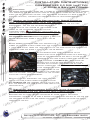
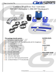
O
RK
O
T
C
R
KSP
O
P
OR
T
S
C
R
K
O
R
T
SP
R
K
G RT CO
O
R
SP
CO
K
O
R
P
eS
CO
RT
O
P
ORKn
S
C
RT
K
O
R
P
O
T
S
CorkSport
Turbo InletRKPipe
C
OR
P
S
- PORT w/ Recirculation & Breather
CO Fitting
K
R
O
T
S
C
OR
RK
P
S
CO6
RT
K
O
R
P
O
C
RT
KS
O
R
P
O
T
C
KS
R
4 RKSPOR
O
T
C
R
O
P
O
T
C6
R
KS
O
R
P
O
T
S
C
R
K
O
R
2
SP
CO
RT
K
O
R
P
CO
RT
KS
O
R
P
O
C
RT
KS
O
R
P
O
T
S
C
R
K
O
R
P
O
T
S
C
R
K
O
R
P
O
T
S
C
R
K
O
P
S
COR
RT
K
O
R
P
O
T
C
KS
OR
R
O
T
SP
R
NOTE: These
instructions
were written for reference onlyC
and the use of a
K
O
R
P
O
Tthese instructions
S manual is recommended. Please
factory
service
read
C
R
? O
K
O
R
P this inlet pipe is
prior to starting installation. S
Because
T
Cthoroughly
R
K
O
R
intended
for
use
with
a
v
takes
that
connect
to
the
factory
COto the installation instructions forORKSP
RTinlet pipe, it is important to have
O
access
P
T Inlet Pipe has a connection for aC
S
RCorkSport
your particular intake. This
O
RK
P
O
T
valvecover breather
hose and includes a silicone hose that replaces
your
S
C
R
K
O
factory clip-lock
P
S
CORbreather hose.
RT
K
O
R
P
O
T
S
C removal of battery box and Vehicle
R ! WARNING: Disconnection
of battery,
K
O
R
P
O
ECU are required for installation.
Consult factory service manual C
or
RT
O
RKS
P
owners manual for
your
car
for
spe
tails
on
disconnection
of
O
T
S on the battery can cause SERIOUS
C
R
K
O
R
Battery. Bridging
the
terminals
damage
to
P to battery weld
Swant
CO and can cause injury. Plus, YouORdon’t
RT
K
vehicle electronics
O
P
T
anyRparts together today - trust us - be careful.C
KS
O
R
P
O
T
S
C
R
O
P
ORKGen-6-462
T
S
MazdaSpeed3
All
2007-2010
C
R
K
O
R
P
O
MazdaSpeed6
2006-2007
T
All
60-90 min
S
C
R
K
O
R
P
O
Mazda
CX-7
MZR
2.3
DISI
Engine
Only
T
2007+
C
KS
2/5
OR
R
P
O
T
S
C
K
OR
P
T
S
COR
K
OR
P
S
COR
RT
K
O
R
P
O
T
S
C
R
K
O
R
P
O
C
RT
KS
O
R
P
O
C
RT
KS
O
R
P
O
T
C
RT
KS
O
R
P
O
T
C
KS
OR
R
P
O
T
S
R call 360-260-CORK (2675) T C
K
O
R
P
O
For
help
with
installation,
C
R
KS
O
R
P
O
T
C
R
O
RKS
CORKSPORT
Mazda Performance Brand
www.CorkSport.com
Part Number:
Model
Year
Trim
Time Estimate:
Wrench Rating:
3/8 Drive Ratchet
6” 3/8 Drive Extension
8mm long socket
10mm Long Socket
12mm Long Socket
Phillips Screwdriver
Longnose Angled Pliers
Channel Lock Pliers
Silicone Spray
Flashlight
CorkSport Turbo Inlet Pipe w/
tting & Crankcase
Recircula
Breather Fitting
2x 63-71mm T-Bolt Band Clamps
54-57mm Silicone Reducer
6” Long, Smaller ID Silicone Hose
12” Long, Larger ID Silicone Hose
RK
O
T
C
R
O Installation
R
Instructions:
P
O
T
S
C
R
K
O
R
Inlet
T
SP CorkSport Turbo
CO
R
K
O
R
T
SP
CO
R
K
O
R
P
the InstructionsRWork
T
S How
COfamiliarity with
O
best cover all of
our
customers
experience
levels
and
P
ORK To
T
C
Rinstructions
KS Mazda, we have broken
the systems on R
their
our
down into
O
P
O
T
S
C
numbered steps, each of which has theR
core
Rhigh
K information in the header
Oawith
P
O
T
additional
detail as needed depending
on your experience. If you have
S
C
R
K skip to
O of experience, you canRjust
R
level
use the checklist below and
then
P
O
T
S
C
K
Oneed
step number where P
you
help or assistance. Video assistance may
S
COR the
RbyTthe HD icon: Areas T
also be available for
certain
steps
and is indicated
K
O
R
P
O
where there isC
a safety concern are indicated
the warning icon: !
KSbyare
OR
R
Cautionary
areas
(where
parts
are
fragile,
etc)
indicated by the caution
P
O
T
S
C
R
O? Key tips are indicatedRwith
icon:
the light bulb icon:
RK
P
O
T
S
C
K
O
P
T
S
COR
R
K
O
R
T
SP
CO
R
K
O
R
SP
CO
RT
K
O
Overview/Checklist:
R
P
T of the build. You can use
COthis as a
Rsteps
KSis an overview of each of
This
the
O
R
P
O
C reference and a checklist
on the
RTcar.
KasS you button up the work
O
R
P
O
T
S
C Cover
R
K
O
R
1: Remove Intercooler
P
O
T
S
C
R
K
O
R
P
O
T
S
2: Remove
Battery
Cover
C
R
K
O
R
P
S
C3:ODisconnect
RT
K
O
R
Battery Terminals,
Hold Down Bracket & P
Battery.
O
T
C
KS
OR
R
O
T
C three harness loom ORKSP
R box front cover, disconnecting
4a: Remove battery
O
P
T
strap connectors
from cover.
S
C
R
K
O
R
P
O
T
C
R
KS
4b: Remove ECU cover.
O
R
P
O
T
C
R
KS
R
O
T
SPO 4c: DisconnectPthe
two
ECU
plugs.
C
OR
RK
O
T
S
C
R
K
O
5a: Disconnect
P
S
COR MAF sensor harness.
RT
K
O
R
P
O
T
S
C vehicle.
from
R5b: Remove factory airbox
K
O
R
P
O
T box from vehicle. C
Rbattery
O
RKS
5c: Unbolt and remove
P
O
Tto it!
S place - your ECU is connected
C
R
K
Put into a R
safe
O
SP
CO
RT
K
O
R
P
O
T
6a:
Remove
valvecover
breather
hose.
C
KS
ORTip to use bent paperclip
R
to unclasp the breather connectors.
P
O
T
S
C
R
O
P
ORK 6b: Remove factory
T
S
C
R inlet.
turbo
K accordion flex hose from
O
R
P
O
T
S plastic turbo inletPpipe.
C Recirculation hose from
R
Kfactory
O
R
6c: R
Disconnect
O
T
C
KS
O
R
P
O
T
S
C bracket by
K
Disconnect factory plastic
valvecover
OR turbo inlet pipe from
T
COR 6d:
removing 10mm nut. KSP
OR
P
OR
S
C
RT
Kfactory inlet pipe.
O
R
7a: Remove
wiring harness loom clips from
P
O
T
S
C
R
K
O
R
P
O
Remove boost control solenoid
C
Rup,Tnotline.
K7b:STake
O
R
P
O
care
to
pull
it
directly
on
angle.
C
RT
KS
O
R
P
O
T
C inlet pipe from turbocharger
KSand out of the vehicle.SPORT
7c: Remove plastic
R
O
T
C
OR
RK
P
O
T
S
C
R
K
O
P
T
For help with
installation,
call 360-260-CORK
(2675)
S
COR
R
K
O
R
CO
RT
O
RKSP
O
CORKSPORT
KSP
CS
O
RK
O
T
C
R
KSP
O Installation Instructions:
R
P
O
T
S
C
R
C
K
O
R
P CorkSport Turbo InletORT
O
S
C
K
R
O ORT
SP
CO
K
R
P
S
CO
RT
(continued): SPO
ORKR Checklist
T
C
R
K
8: Assemble the CorkSport
Turbo Inlet Pipe and hoses.
O
R
P
O
K
T
S
C
OR
RKbracket.
P
O
T
9a: Install
CS Turbo Inlet to Turbocharger and valvecover
S
C
R
K
S KSPO
R
O
T
C
valvecover
OR bracket stud.
P
T
S
COPR 9b: Install CS Turbo InletOonto
R
K
O
R
P
9c: Install 12” long, larger
C ID valvecover breather hose between
RT
KSCS Inlet and
O
R
O Valvecover
breather.
P
O
T
C
KS
OR
R
P
O
T
S
R to boost control solenoid. T C
hose
RCORK9d: Connect 6” long, smaller ID silicone
O
P
S
R
Khose
O
R
P
onto
CS
Inlet
Pipe.
O
T 10a: Install factory recirculation
T
S
C
R
K
O
R
SP
C- O
RTsystem (Cobb, Injen, AEM, Mazdaspeed
K
10b: Install
intake
pick y
avor)
O
R
P
T
S
CO
R
K
O
R
P
O
S
C 11a: Install battery box and 3 10mm
RT
Kbolts.
O
R
P
O
T
S
C
R
K
11b: Install ECU connectors and ECU Cover.
O
R
P
O
T
S
C
R
K
O Hold Down Bracket, Front of Battery
R
P
O
T
S
11c: Install
Battery,
Box and wiring
C
R
K
CclipsORonto front of battery box. ORKSPO
RT
O
P
T
11d: Install intercooler cover. C
KS
OR
R
P
O
T
S
C
R
K
O
R
P
Start the car, ifS
issues, check for leaks at silicone couplers
O
Tand MAF
C
R
K idle
O
SensorO
toR
MAF
Housing on your intake pipe.
T
SP
C
R
K
O
R
CO 21wheel horsepower. ORKSP
RT Buy a CorkSport Downpipe and
get another
O
P
S
C
RT
O
RK
P
O
T
S
C
R
K
O
P
S
COR
RT
K
O
R
P
O
T
S
C
R
K
O
R
P
O
C
RT
O
RKS
P
O
T
S
C
R
K
O
R
SP
CO
RT
K
O
R
P
O
T
C
KS
OR
R
P
O
T
S
C
OR
P
ORK
T
S
C
R
K
O
R
P
O
T
C
R
KS
O
R
P
O
T
C
KS
OR
R
P
O
T
S
C
K
OR
P
T
S
COR
K
OR
P
S
COR
RT
K
O
R
P
O
T
S
C
R
K
O
R
P
O
C
RT
KS
O
R
P
O
C
RT
KS
O
R
P
O
T
C
RT
KS
O
R
P
O
T
C
KS
OR
R
P
O
T
S
C
R
K
O
R
P
O
T
For
help
with
installation,
call
360-260-CORK
(2675)
C
R
KS
O
R
P
O
T
C
R
O
RKS
RK
O
T
C
R
O Installation
R
Instructions:
P
O
T
S
C
R
K
O
R
CorkSport
Pipe
PMZR 2.3 DISI Inlet
T
S
CO
R
K
O
R
Fittings
P
Ow/ Recirc & Breather
TRemove Intercooler Cover
S
C
R
K
O
1:
R
Tintercooler cover is attachedCO
SP
R
The
with two 10mm bolts
K
O
R
O
connect the the cover
to the intercooler. Use
SP which
C
RTdrive
K
O
R
your
10mm
Socket
and
3/8”
ratchet to remove
the
P
O
T
S
C
Rthe
Kin Diagram 1. Lift the front
two bolts shown
of
O
R
P
O
T
S
C
R
intercooler cover off of the intercooler
and push the
Kof
O
R
P
O
T
S
entire
cover
toward
the
firewall
and
off
C
R back of the intercooler.TLift the covertheoutcatch
K
O
R
P
O
at
the
of
S the engine bay and placePitOon
C
R
K
R
your
workbench.
CO
RT
KS
O
R
P
O
T
C
KS
OR Diagram 1
R
P
O
T
S
C
R
K2: Remove the Battery
O
R
Cover.
P
O
T
S on with two clips POR
C The battery box coverORisKheld
T
shown in DiagramC2, pry the clips outward byRKS
R
O
hand and lift
the front of the lid upward and
SP
CO then
K
OlidRT
R
pull S
the
forward out of the latchT
mechanism at
P
CO
R
Kback of the box.
the
O
R
P
O
C
RT
KS
O
R
P
O
T
C Terminals, HoldORKS
R
O
3: Disconnect
Battery
P
T
S
C
R
K
O and Battery. RT
Down Bracket
R 2
P
O
S
Diagram
C
K
A) Use
a
10mm
end
wrench
and
disconnect
the
Oone nearest the firewall),Rplace
P
OR terminal of the battery
T the battery
S
Cnegative
(the
K
O
R
P
O
negative
lead
out
of
the
way
between
the
battery
box
and
fenderwell,
T
Cpainted fender. DisconnectORtheKSpositive lead making
OR
sure not to scratch
the
the
P
T pull the leads clear of theCfront of the batteryusing
R
K
10mm end wrench
and
to
make
itS
O
R
P
O
T
S the battery.
easier to
remove
C
R
K
O
R
P
T 3b
Sthe
CO
R
K
O
R
B)
Remove
two
10mm
nuts
shown
in
Diagram
SPand lift the
COthe battery hold-down O
RT
K
O
from
bracket
R
P
S
Cplacing it on your
RT bracket free of the studs,
O
RK
P
O
T
workbench.
S
C
R
K
O
P
T place it
S
COR
Rand
K
C) Lift O
the
Battery free of the battery P
box,
O
R
T
S
C location.
R
in a safe
K
O
R
P
O
C Cover, ECU
RT
O
RKS
P
4:
Remove
the
Front
Battery
O
T ECU Plugs.
S 3b Cover, and Disconnect
C
R
K
Diagram
O
R
T
SPplace on two grooves inPthe
CObattery cover is just slid
Rmain
K
A) The front
into
O
R
O
T
Citself.
box, and it sits on two pegs
that are at
R top front
KS
Obattery
R
P
the
corners
of
the
box
However,
O
T
S
OR loom straps that RT C
are three wiring
harness
P
ORK there
S
C
K the battery box by a setSofPO
are held in placeRto
O
T
C
push lock connectors.
These are removed
R
Kby
O
R
P
O
T
compressing
their
latching
features
with
a
pair
of
C
KS
OR or straight needle nosed
R
angled
pliers and
P
O
T
S
C
R hole they are
K
O
them back through
the
P
T
S
COR pushing
attached to. It is helpful
to then pivot them out OR
RKnot reconnect
Odo
of the way so they
into the KSP
C
RT
O
R
hole. Remove
all
three
of
these
connectors
P
O
T
S 4a
C
R
K
O
shown
in diagram 4a and remove the front cover
R
Diagram
P
O
C
RT
K
ofSthe battery box.
O
R
P
O
C
RT
KS
O
R
P
O
T
C
RT
KS
O
R
P
O
T
C
KS
OR
R
P
O
T
S
C
R
K
O
R
P
O
T
C
R
KS installation, call S360-260-CORK
For help R
with
(2675)
O
P
O
T
C
R
O
RK
O
CORKSPORT
KSP
1
1Now would be a good time to take a look at your intercooler and see if you have any bent fins or debris
lodged in the intercooler fins or between the fins and the cover or tanks. removal of any and all debris
and straightening of the fins will improve the performance of the unit.
RK
O
T
C
R
O Installation
Instructions:
R
P
O
T
S
C
R
K
O
R
CorkSport
Pipe
PMZR 2.3 DISI Inlet
T
S
CO
R
K
O
R
Fittings
P
Ow/ Recirc & Breather
T
S
C
R
4
(Continued):
K
O
ORcontrol unit (ECU)
SP
b)T
Remove the cover from the engine
C
R
K
O
R
O
disconnecting the latch
attaches the front of C
Tthat
SP by
Rbox
K
O
R
the cover to the battery
and ECU shroud. See
P
O
T
Slocation of ECU cover andPlatch.
C
R
K
Diagram 4b for
O
R
O
S
C
RT
K
O
R
P
O
C) R
Disconnect
two ECU plugs by
the
Tbelow thethe
Cofdepressing
KS
O
R
hasp
white
camlock
latch
the
plug
P
O
C
RT
KS housing. When the hasp
is
O
R
P
O
T
S
C
depressed, lift the
white
R
K
O
R
P
O
T
mechanism
C which will
KS
OR Diagram 4b latch
R
P
unlock and
disconnect the
O
T
S
C
R An example
Kecu plugs. both operate identically.
O
R
P
O
T
S . When done correctly, POR
C can be seen in diagram
4c
K
R
O
T
this process should
S
C be effortless.
R
K
O
R
SP
CO
RT
K
O
R
P
CO
RT
KS
O
R
P
O
T Diagram 4c
SSensor, Remove
C 5: Disconnect theOMAF
R
K
O
R
P
T
the Airbox and C
R
KS
O
R
Battery Box.T
P
O
S
C
R
K
A) The Mass Airflow (MAF) sensor, shown inR
O
P
O sealed
T
S
C
diagram
5a is plugged in with a latch lock
R
K
O
R
Press
(A)
and
P
O
connector.
Press down on the latch
top of
S
CLatch
RT on the
K
O
R
the
connector
and
pull
on
the
connector
with
one
Will
Release
P
O
T
SMAF housing and airbox
C hand while supportingORthe
K
OR
SP
C Unlike the ECU connectors,
RT Clasp with the otherThand.
K
A
O
R
P
O
S
this one can
often times build up a strong C
surface
R
K
O
R
tension
between the sealed o-ring and
mass
Tthe
SPsensor
CO
R
K
O
R
airflow
housing,
so
you’ll
have
to
pull
SP
COhard. When you push down
RT
on
the latch, you will
K
O
R
P
O
T
S
see
the
latch
lift
up
a
retaining
clasp. If the claspK
C
R
O
P
does not moveRup,
you’re not going to pull theCOR
T
S
K
O without breaking it, so push
out
P
T the
S
COR Diagram 5a connector
R
K
latch
down harder rather than pulling
the
O
R
P
O
T
S
C
R
connector harder.
K
O
R
O
T to the car using a single 12mm
C
R
O
RKSP B) The Airbox is connected
and a pair of
O
Tgrommetsbolt
SP that connect into two Prubber
C
R
K
push-in plastic
nubs
below
the
airbox
as
O
R
O
T
Sinlet pipe to the airbox. Once
well as aC
10mm hose clamp attaching R
the
you
R
K
O
P
O
T
the
S 10mm bolt
C box to the vehicle, backOoff
R the 12mm bolt attaching
Kthe
Oremove
R
P
on the hose clamp attachedT
to the rubber accordian inlet pipe
and push the pipe
S
OR
off of the airbox. C
Pull the airbox up and
P
ORK
T compartment
S
C
R
K
out of the
engine
(the
O
R
P
O
T
detents
will hold it R
fairly
C
KSandandsetgrommets
O
R
tight.
it
on
your
workbench.
You
P
O
T
S in the
C will remove the MAF Sensor
R
K
O
later
R
P
O
RT
KS
instructions prior to C
installing the new
O
R
P
O
C
intake, and can
leave it in place for now.
RT
KS
O
R
P
O
T
S
C
Rthe
K the three 10mm boltsSfrom
O
R
C)ORemove
P
T
Cfloor of the battery box shown
R
K in
O
R
P
O
T
S
C
diagram 5c using a ratchet, 10mm
K
OR
P
socket
and 6” 3/8
drive extension. You
S
COR
RtoT
K
O
R
will
now
be
able
P
O
T
S from extract the battery
C
RT
K
box and
ECU
O
R
P
O
T
Diagram
5c
C
KS
OR
R
P
O
T
S
C
R
K
O
R
P
O
T
For
help
with
installation,
call
360-260-CORK
(2675)
S
C
R
K
O
R
CO
RT
O
RKSP
O
CORKSPORT
KSP
RK
O
T
C
R
O Installation
Instructions:
R
P
O
T
S
C
R
K
O
R
CorkSport
Pipe
PMZR 2.3 DISI Inlet
T
S
CO
R
K
O
R
Fittings
P
Ow/ Recirc & Breather
T(Continued):
S
C
R
5:
K
O
ORthe wiring harness
T are a number of elements Cfrom
SP the engine compartment.
There
R
K
O
R
P so often times an extra OsetRT
O
that surround the box,
of hands can be helpful to
S
C
K
R
clear the way O
to extract the box. Put the boxP
on the bench in a safe place as
it
T
S
C
contains your ecu, the brain and nervous
OR
RKsystem of your MazdaSpeed3.
P
O
T
S
C
R
K
O Remove the Valve Cover
R
P
O
6:
Breather
Hose,
Rubber
accordion
T
S
C
K
OR Inlet pipe Bracket.RT
Recirculation
Hose,
P
S
COR hose,
K
A) The valvecover
breather
hose is a tricky one P
R
O
S asOit uses two clip lock PORT
C
connections. you can use two screwdriversRto
K
O clips
T of the latches on the internal
releaseReach
C
KS
O
R
P
(green
on the valvecover, blue onT
the inlet
O
S
C
Kaccordion hose), ? But there
O
R
is R
a much easier way by
P
O
T
S out of a paper clip POR
C fashioning a releaseOmechanism
K
R
T
shown in diagramC6a. Unclip each of the endsK
of
S
R
O
R
the valvecover
hose and remove it
Obe the
SP
Cfrom
RT breather
K
O
engineP
compartment
store it away, it will
not
R
CO
RT
KS
reused.
O
R
P
O
T Diagram 6a
S
C
R
K
O
R
P
O
T
B) The rubber accordion
that connects the
S the turbo inlet pipe withPO
C hose
R
K
R
airbox to the hard
plastic
turbo
inlet
pipe
is
held
onto
O
S
C the hose clamp and extract
RT Back the 10mm boltTout of
K
a 10mm hose
clamp.
the
O
R
P
O
C
accordion
itO
will
R not be reused.
KS hose and store it away,
R
P
O
S recirculation hose is attached
C
RTto the
KThe
O
R
C)
P
O
T
C recirculation valve (sometimes
KS known as a blow-off SP
OR
R
O
T
C and onto a fitting onOthe
valve) on the intercooler
K
OR
R
P
T
S
underside
of
the
hard
plastic
turbo
inlet
pipe
on
the
C
R
K
O in diagram 6c. Both
other, S
asPshown
ends are
T
COR
R
K
O
R
retained
with
a
pair
of
hose
clamps
that
be
P(or by can
O
T
S
C
R
released with channel lock R
pliers
hand if
K
O
O pliers to release the RK
SP
a masochist). use
the
C
RT you’re
O
P
tension and
CO
RtoTmove
KSDiagram 6c clamp
O
R
the hose clamps
the
P
O
C
RT
KSthe hose away
centerR
of
O
P
O
T
C off of the fittings ORKS
Rfrom
the fittings. Pull the hose
O
P
and place it onto your R
workbench.
T
C
O
RKS
P
O
T
Sdisconnect the 10mm nutPthat
C
R
K
D) Finally we
will
O
R
O
T
holds theChard plastic turbo inlet pipe
inSplace.
R
K
O
R
P
O
T
remove
nut and
Chosethe
R Diagram 6d for location,
KS Diagram 6d
OSee
R
P
pull the grommet and hard plastic
free of the
O
T
S
C
ORK mounting stud. RKSPOR
T
C
R
O
P
O
T
7: Disconnect
harness Clips
Intake, Disconnect R
Sfromturbocharger.
C Wiring
Kfrom
O
R
Boost
Solenoid
Line
and
Inlet
pipe
P
O
T
S
C
R
K to it.
OThe hard plastic intake pipeRT
A)
has two wiring harness clips attached
R
P
O
S
C
K
each of these are O
well concealed by other items in the engine
P
T pipe out of the car and
S
COR Because
compartment, diagramK7a
on page 4 shows the turbo inlet
R
O
R
P
O
the locations ofCthe clips are marked for clarity.
RT
KS Remove the clips andSpivot
O
R
them out of
the way.
P
O
T
C
R
K
O
R
P
O
T
S
C
K
OR
P
S
COR
RT
K
O
R
P
O
T
C
RT
KS
O
R
P
O
T
C
KS
OR
R
P
O
T
S
C
R
K
O
R
P
O
T
For
help
with
installation,
call
360-260-CORK
(2675)
S
C
R
K
O
R
CO
RT
O
RKSP
O
CORKSPORT
KSP
O
RK
O
T
C
R
KSP
O Installation Instructions:
R
P
O
T
S
C
R
C
K
O
R
CorkSport MZR
P2.3 DISI Inlet Pipe ORT
O
S
C
K
R
O ORT
Ow/ Recirc & Breather Fittings
SP
C
K
R
7:
(Continued):
P
S
CO
RT
O
P
ORKR B)
T
S
C
R
tting is
K
O
R
SOLENOID
P
O
K marked
T
on diagram
7a. Remove the hose clamp from KS
C
OR
both ends
of the line att
tting by COR
P
T
S
R
K
S KSPO
R
O
T
C
tting on the turbo
pipe and
ORinlet
P
S
COPR the boost control solenoid.
Great
care
should
be
RT
Kon the boost control
O
R
P
O
taken with the end of
the
line
T
C
R
KS
O
R
itT
is a plastic housing. If you have
O solenoidlty,Oastry
P
O
Diagram
S 7a
R rotating the hose to break the sealT C
K
R
P
O
S
then
straight up. It does take
C
Rpulling
RCORKof the rubber to the pl tting lyand
O
P
if
pulled
in
line
with
the
att
tting.
T
R
O
RKS
P
T C) Finally, we are goingCtoOremove
T
S
R
K
the plastic inlet pipe from R
the
turbocharger.
O
Tand model, the inlet pipe will most likely
SP
COhave a hose clamp
DependingO
onR
year
K
R
P
thatK
isS
actuated with a pair of pliers, but on some
models and years there is a
CO
RT
O
R
hose
clamp
with
an
8mm
bolt.
Back
the
hose
cl
lastic
P
O
C
RT
K.SThe stud that mechanically mounts
the
O
R
P
O
T
R
inlet pipe to the bracket mayC
have fallen back into place, so make sure
itSis
K
O
R
P
O
T
removed (see stepR
6d,
Page 3). Extract the plastic turbo inlet C
pipe and put it in
S
K
Obe re-used.
R
P
a box, it will
not
O
T
S
C
R
K
O
P
S
C8:ORAssembling and InstallingOthe
RT
K
Corksport
Power Series Turbo
O
R
P
T
C
Inlet Pipe.
KS
OR
R
O
T
Cclamp that holds the silicone tubing to theORKSP
R as shown in diagram 8a. As seen, the t-bolt
Assemble the turbo inlet
pipe
band
O
P
T but still loose on the silicone coupling. TheC2”
S
turbocharger K
compressor
housing should just be tightened downR
slightly,
O
R
diameter
ared
end connects to the Corksport turbo inlet pipe,
TBoostwith the
SP2.25”
COend connects to the turbocharger whiletheRthesilicone
R
K
O
band clamp 10mm fastener tightened. Each ofO
hoses - the 6” long, smaller (ID) short hose
for
the
SbePlubricated with silicone
RT Control Solenoid and the 12” long,T
larger IDC
hose for the valvecover breather connection R
should
K
O
P
S
CO
R
O
RK
P
O
T
S
C
R
K
Oto
Caution
IDP
hose
?
S
CORshould be taken when installing theOsmaller
RT
K
O
R
P
T
S
C
Rand can bend if too much pressure is applied.
K
O
R
P
O
C
RT
O
RKS
P
O
T
S
C
R
K
O
R
OSolenoid
9: TurboCInlet
Installation, Valvecover Hose Installation
SPand
RT
K
O
R
Boost
Control
Hose
Installation.
P
O
T
C
KS
OR
R
P
O
T
S
tted
down
between
the
ECU
C
ORsimilar to the
harness and the valvecover,
P
ORK wiring
T
S
C
R
Khard plastic turbo inlet.
O
R
orientation of the factory
P
O
T
R
Feed the siliconeC
coupler end of the inlet down in
KS
O
R
P
O
T
the given
space
toward
the
turbocharger
compressor
C
Diagram8a
8a
KSDiagram
ORinlet avoiding ca
R
P
housing
ttings
and
lines
O
T
S
C
K
ORand components in the vicinity.RAlign
turbo inlet on the wiring harness
P
T
S
COR ofthethebracket
KTurbo Inlet pipe with the stud on the
on the Corksport
valvecover
O
P
O2”Rdiameter
S
bracket and connectC
the
silicone coupling over the
end
of the
RT
K
O
R
P
O
turbocharger
compressor
inlet,
taking
care
to
keep
the
loose
band
clamp
in
T
S
C is probably too tight.
R
K
R
pl SPO
ly - if not, the t-bolt band
clamp
O
C
RT
K
O
R
P
O
C
RT
KS
O
R
P
O
T
C
RT
KS
O
R
P
O
T
C
KS
OR
R
P
O
T
S
C
R
K
O
R
P
O
T
For
help
with
installation,
call
360-260-CORK
(2675)
C
R
KS
O
R
P
O
T
C
R
O
RKS
O
RK
O
T
C
R
KSP
O Installation Instructions:
R
P
O
T
S
C
R
C
K
O
R
CorkSport MZR
P2.3 DISI Inlet Pipe ORT
O
S
C
K
R
O O9:RT
Ow/ Recirc & Breather Fittings
SP
C
(Continued)
K
R
P
S
CO
ORT Turbo Inlet over the stud onRT
P
ORKR B)factory
Attach the bracket onS
the
Corksport
the
C
O in
RK and start the nut onto the stud asSindicated
valvecover O
bracket
P
K Diagram
T
C
9b. Check to ensure that the silicone coupling
fully engaged
OR
RKis still
P
O
T
between
the
turbocharger
and
turbo
inlet
pipe
and
tighten
the
nut
the
rest
of
S
C
R
K
S KSPO
R
the
way.
Then
tighten
the
t-bolt
band
clamp
at
O
T
C
R
O
R
the
turbocharger
compressor
inlet.
This
has
to
SP
COP
RT
K
be tight.
O
R
P
O
C
KS larger ID breather hose SPORT
R
O
O
T
C)
Feed
the
12”long,
C the wiring harness toward the ORK
OR
underneath
P
T
S
Rvalvecover brea tting as shownTin C
RCORK
O
P
R
Diagram 9c.
KS Apply
O
R
P
O
T
a
small
T
S
C
R
K
O
R
amount
of
SP
CO
RT
K
O
silicone spray to
R
P
T of the
CO
Rinside
Diagram 9b
KS
the
O
R
P
O
S thehose and to the
C val
RT
Kover
O
R
P
tting
and
slide
the
hose
O
T
C
R
KS
O
R
tting up to the stopT
collar. If there are any
P
O
S
C
R
kinks in the hose,
re-evaluate
the
routing...this
K
Ocrankcase from ventilating RT
R
P
O
S
will prevent
your
C
K
O
P
OR
S
Cproperly.
RT
K
O
R
P
O
T
C spray onto
KS
Diagram 9c
D) Apply a small amount of silicone
OR
R
O
T
SP
C
R
the free end of the 6”
long
smaller
ID
hose
and
K
O
R
P
O
T
connect it toKthe
S boost control solenoid outlet. BePGentle.
C
R
O
R
T
S Intake Installation.
CORecirculation Valve Hose Installation,
R
K
10:
O
R
SP
COhose between the recirculation valve
RT A) Install the factory recirculation
K
O
R
valve
P
O
T Turbo Inlet. The bent end of this Chose
S
RCorksport
O
and the lower pipe on
the
RK
P
O
T
S
C
R
K
O tousing
R Recirculation valve. The other endbeSconnects
connects toO
the
the lower
P
RT
DiagramO
10a
pipe on C
the Corksport Turbo Inlet. Both ends will
secured
the
K
R
P
O
T
S
C 10a.
Rfactory spring clamps as shown inTDiagram
K
O
R
P
O
C
R
O
RKS
P
O
T have
Spipe assembly is installed and all ofPtheOconnections
C
R
K
B) Now that the
inlet
R
O inlet pipe, you’re ready to installRyour
Cthe
been made to
intake system. Your
RT
KSthat
O
P
O
T
intake
installation
will
of
course
require
the
MAF
sensor
is
still
connected
C
KS
OtoRyour OEM airbox that you removed
R
from the vehicle. Start your intake
P
O
T
S
Rthe references to the factory turboTinlet C
instructions and replace
O
P
ORK installation
S
C
pipe with the CorkSport
KTurbo Inlet Pipe and you should beSallPset.OR
R
O
T
C
R
K Battery and Covers.
O
R
11: RT
Installation of Battery Box, ECU Connectors,
P
O
C
KS
O
R
P
O
T
S
C
R fastening into the chassis with the
K A) Install the battery box backSinto
place,
O
P
T
COR three
10mm bolts through the
base
of
the
box.
Feed
the
battery
terminal
lines
R
K
P
through the cutouts C
in O
theR
box as shown in Diagram 11a, on page
6. O
S
RT
K
O
R
P
O
T
S
Rthe ECU connectors and latch the cam
B) Install
locksCto seat the connectors
K
O
R
P
O
T
the
C
Rconnectors.
KintoSthe ecu. Install the ECU cover over
O
R
P
O
C
RT
KS
O
R
P
O
T
C
RT
KS
O
R
P
O
T
C
KS
OR
R
P
O
T
S
C
R
K
O
R
P
O
T
C
R
For help withRinstallation,
call 360-260-CORK (2675)
KS
O
P
O
T
C
R
O
RKS
RK
O
T
C
R
O Installation
Instructions:
R
P
O
T
S
C
R
K
O
R
CorkSport
Pipe
PMZR 2.3 DISI Inlet
T
S
CO
R
K
O
R
Fittings
P
Ow/ Recirc & Breather
T (Continued)
S
C
R
K
11:
O
ORtoward the
Tthe battery box (Negative terminal
SP C) Install the batteryPOinto
C
R
K
R
O
firewall) and install
hold down bracket over R
the
studs on the box.
Ttwoand
S the
C
Kon
O
R
There is a diagram
the bracket that shows
‘Forward’
an arrow which T
P
O
S
C
R
KInstall the two 10mm flange
should point toward the front of the car.
nuts
O
R
P
O
T
S
C
R
onto
studs. Install the positive
K
O thecable
R
P
O
T
battery
onto
its
terminal
and
S
C
R
K
Otight.
the 10mm nut hand
P
S
COR tighten
RT
K
O
Install the negative
battery
cable onto
R
P
O
Ctighten the 10mm nut ORKS
RT
its terminal and
O
P
T
hand tight.
Install the front cover
C
KS
OtheR battery
R
P
onto
box and snap the
O
T
S
C
Ras
Kwiring harness clips into Splace
O
R
P
O
T
C shown in diagram 4a,OPage
R
K 1. Install
O
R
P
T
C into place and latch ORKS
the battery box top
R
O
the two latches
SP
RT on the forward sidesTof C
K
O
R
the box.
P
CO
R
KS
O
R
P
O
T
S
C D) Install the intercooler
cover,
R
K
O
R
P
O
T
making sure that the C
metal bracket
S
R
K
O
R
under the cover
is
latched
onto
the
tab
P
O
T
S
C
R
Diagram
11a
K
O
in the back
of the intercooler tank
R
P
O
T
S
C
R
casting.
Lower
the
front
of
the
intercooler
cover
and
align
the
clearance
K
O
P
OR in the cover with the tapped
holes and install the two 10mm
S
Choles
RT head bolts
K
O
R
hand
tight.
P
O
T
C
KS
OR
R
P
O
T
R car: You are now ready
StartingPthe
toCstart the car, if there are RKS
O
O
T- hose clamps for tightness Cand
Sthe idle, check your connections
issues with
R
K
O
R
Pfully seated in the placeOit Rconnects
check
to make sure the MAF sensorSis
to
Tthe housing
COintake
K
R
your
pipe,
and
not
cocked
at
a
non
parallel
angle
relative
to
P tightness.
O
Sfor
RT surface. After a testTdrive,Crecheck
K
all hose clamps again
O
R
P
O
S
C
R
O
RK
P
O
What’s Next:
Now that you have improved
the induction on your MZRC2.3
T
S
R
K
O with your Power SeriesRT
R consider opening up yourSexhaust
DISI Engine,
Turbo
P
O
C
K
Back Exhaust system featuring:
O
R
P
O
T
S
C
R
K
O
R
O
T Downpipe
Power Series
C
R
O
RKSP CorkSport
The other logical
to go with your Speed3,
Speed6 or CX-7 is to
O
TPower
SPdirection
C
R
K
O
R
open up the
exhaust
system
with
the
CorkSport
Series
Downpipe.
With
SPturbine and wastegatePoutlets,
CO
RT the
separate
K
O
R
O
T
not only increases
tubing size
Sprevents
Cdownpipe
Kthe
OR
R
P
of
the
factory
unit,
but
also
the
O
T
S
C
R
K
O
R
disruption
of
flow
at
full
boost
by
P
O
Tblowing perpendicular to C
S
R
K
wastegate gasses
O
R
T
SP flow out of the turbocharger.
CO
the exhaust
R
K
O
R
Pup which
This
faster turbo spool
SGains
COgivesin you
RT
K
O
R
results
a
larger
power
band.
P
O horsein
T power have been up to 21Cwheel
S
R
K
O
R
T on otherwise stock
SP
CO
power when installed
R
K
O
R
P
O
MZR 2.3 DISI
The CorkSport
S Engine.
C
RT
Kor
O
R
downpipe T
bolts to the stock second catalyst
aftermarket racepipes.
It
is
P
O
SSeries
C system featuring the Power
R of our Turbo Back Exhaust
K
O
theP
lynchpin
R
O
S
C CatBack
RT High Flow Catalyst) T
Racepipe (with or without
and 80mm
KDownpipe,
O
R
P
O
C Exhaust.
KS
OR
R
P
O
T
S
C
RT
K
O
R
P
O
T
C
KS
OR
R
P
O
T
S
C
R
K
O
R
P
O
T
For
help
with
installation,
call
360-260-CORK
(2675)
S
C
R
K
O
R
CO
RT
O
RKSP
O
CORKSPORT
KSP