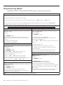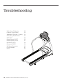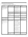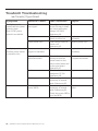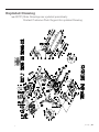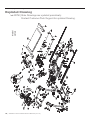
1
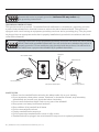
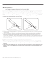
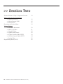
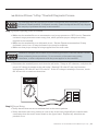
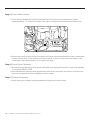
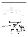
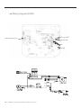
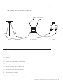
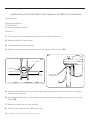
Sears Canada Service Manual
Treadmills
Models
30750, 30727
Table of Contents
>> Table of Contents
Section One
Safety Instructions
Recommended Tools
Parts Diagrams
>> 30750
>> 30727
Maintenance
>> Preventative
>> Lubrication
>> Tensioning & Alignment
Proper Heart Rate Usage
Section Two
3
5
6
7
Horizon Fitness “5-Step” Diagnostic Process
Wiring Diagrams and Schematics
Resetting the Incline Motor
Voltage Checks
Engineering Mode
13
15
18
19
26
Section Three
8
9
10
11
| 2008 Sears CA Treadmill Service Manual [rev 1.0]
Troubleshooting
Exploded Drawings
>> 30750
>> 30727
28
43
44
Section One | Safety Instructions
Safety Instructions
>> Treadmills
WARNING STATEMENTS INDICATE A PARTICULARLY DANGEROUS ACTIVITY.
YOU SHOULD BE EXTREMELY CAUTIOUS WHEN DOING THE FOLLOWING:
• Removing power from the treadmill, or removing the power cord from the wall outlet. Always ensure that the treadmill is unplugged from the wall outlet when you inspect or adjust the treadmill, or when
you isolate, remove, or replace a treadmill component.
• Removing the motor cover exposes high voltage components and potentially dangerous machinery.
Exercise extreme caution when you perform maintenance procedures with the motor cover removed.
• During service operations you will be very close to moving machinery and high voltage components.
When you perform maintenance procedures with the hood removed, remove jewelry (especially from
ears and neck), tie up long hair, remove neckties, and do not wear loose clothing.
• When the treadmill is operating, the capacitor will hold a lethal amount of charge. Do not touch the
capacitor as serious injury or death might result.
• When the treadmill is turned off and the power cord is removed from the wall outlet, the capacitor will
hold voltage for 30-60 seconds. Allow the capacitor to discharge for a period of one minute before you
touch or work near the capacitor. Do not attempt to discharge the capacitor by any other means.
• Exercise caution when touching any wire or electrical component during treadmill operation.
• When it is necessary to lift the treadmill, ensure that the treadmill has adequate support. Do not lift the
treadmill by the front.
SAFETY GUIDELINES YOU SHOULD KNOW AND FOLLOW INCLUDE:
• Read the owner’s manual and follow all operation instructions.
• Operate the treadmill on a solid, level surface. Locate the rear of the treadmill at least four feet from
walls or furniture. Keep the area behind the treadmill clear.
• Visually check the treadmill before beginning service or maintenance operations. If it is not completely
assembled or is damaged in any way, exercise extreme caution while operating and checking the
treadmill.
• When operating the treadmill, do not wear loose clothing. Do not wear shoes with heels or leather soles.
Check the soles of your shoes and remove any embedded stones. Tie long hair back.
• Use care when getting on or off the treadmill. Use the handrails whenever possible. Do not get on or off
the treadmill when the running belt is moving.
• Before starting the running belt, straddle the belt by placing your feet firmly on the guide rails of the
treadmill. You should also step off the belt and onto the guide rails of the treadmill after turning off the
running belt.
• Do not rock the unit. Do not stand or climb on the handrails, electronic console, or motor cover.
• Do not set anything on the handrails, electronic console, or motor cover. Never place liquids on any part
of the treadmill.
• To prevent electrical shock, keep all electrical components, such as the drive motor, power cord, and
circuit breaker away from water and other liquids.
• Do not use accessory attachments that are not recommended by the manufacturer-such attachments
might cause injuries.
• Turn off the treadmill when adjusting or working near the rear roller. Do not make any adjustments to
the running belt when someone is standing on the machine.
• Keep all loose items away from the treadmill running surface. A treadmill running belt will not stop
immediately if an object becomes caught in the belt or rollers.
2008 Sears CA Treadmill Service Manual [rev 1.0] | Section One | Safety Instructions
WARNING
Connect this unit to a properly grounded, dedicated 20-amp outlet only.
See grounding instructions.
GROUNDING INSTRUCTIONS
This product must be grounded. If a treadmill should malfunction or breakdown, grounding provides
a path of least resistance for electrical current to reduce the risk of electrical shock. This product is
equipped with a cord having an equipment-grounding conductor and a grounding plug. The plug must
be plugged into an appropriate outlet that is properly installed and grounded in accordance with local
codes and ordinances.
WARNING
Improper connection of the equipment-grounding conductor can result in a risk of electric
shock. Check with a qualified electrician if you are in doubt as to whether the product is
properly grounded. Do not modify the plug provided with the product, if it will not fit in
the outlet; have a proper outlet installed by a qualified electrician.
Grounded Outlet
Adapter
Metal Screw
Grounding Pin
Grounded Outlet Box
TAS For
Grounding Screw
SAFETY TIPS
• Never use the treadmill before securing the safety tether clip to your clothing.
• If you experience chest pains, nausea, dizziness, or shortness of breath, stop exercising
immediately and consult your physician before continuing.
• Do not wear clothes that might catch on any part of the treadmill.
• Keep power cord away from heated surfaces.
• Keep children off of treadmill at all times.
• Do not use treadmill outdoors.
• Unplug treadmill before moving it.
• Do not remove the treadmill motor cover or roller covers.
• Treadmill should be plugged into a dedicated 20 amp circuit for optimal performance.
| 2008 Sears CA Treadmill Service Manual [rev 1.0]
Section One | Recommended Tools
>> Recommended Tools and Equipment
The following list is a summary of the tools and equipment required by the procedures in this manual.
Tools are not supplied by Horizon Fitness.
• Phillips screwdrivers
• Anti-static wrist strap (when handling electronic parts)
• Flat-head screwdrivers
• Digital multi-meter
• Drive belt tension gauge
• Allen wrench set (Metric)
• Open-end wrenches of assorted sizes (Metric)
• Clamp-on amp meter
• 1/2” drive ratchet and sockets of assorted sizes
• Blue Thread Lock
• Cable ties
• *Motor commutator stone
• Needle nose pliers
• Damp cloth
• Rubber mallet
• Hammer
• Drop cloth
• Ruler
• Snap ring pliers
• Wire cutters
*Available through Horizon Fitness at Cost.
2008 Sears CA Treadmill Service Manual [rev 1.0] | Section One | Parts Diagrams
>> Treadmill Parts Diagram | 30750
Control
Panel
CONTROL
PANEL
Console
CONSOLE
WATER BOTTLE
POCKET Pocket
Water
Bottle
Safety Key
Placement
SAFTEY
KEY PLACEMENT
Console
Mast
CONSOLE
MAST
On
Off Switch
ON/OFF| SWITCH
Motor
Cover
MOTOR
COVER
Circuit
Breaker
CIRCUIT BREAKER
Running BeltRUNNING
| Running
Deck
BELT/RUNNING
DECK
RAIL
SideSIDERail
Roller ROLLER
EndEND
Cap
CAP
RearREAR
Roller
ROLLER
Adjustment
Bolts
ADJUSTMENT
BOLTS
| 2008 Sears CA Treadmill Service Manual [rev 1.0]
Power
POWER CORDCord
TRANSPORT WHEELWheel
Transport
Section One | Parts Diagrams
>> Treadmill Parts Diagram | 30727
SPEAKERS
Speakers
WaterWATER
Bottle
Pocket
BOTTLE
HOLDER
LCD
Display
LCD DISPLAY
Audio
In Jack
AUDIO IN JACK
Console
CONSOLE
Reading
Rack
READING
RACK
Grip Pulse
Handrails
GRIP PULSE
HANDRAILS
Console
MastMAST
Cover
CONSOLE
COVER
Support
SUPPORTBar
BAR
On | Off
Switch
ON/OFF
SWITCH
Circuit
Breaker
CIRCUIT
BREAKER
POWER
CORD
Power
Cord
MP3
Pocket
MP3 POCKET
Console
CONSOLE FANFan
Handlebar
HANDLEBAR
Safety
Placement
SAFETY KEYKey
PLACEMENT
Headphone
HEADPHONE JACK Jack
Console
Mast
CONSOLE MAST
Motor
Cover
MOTOR COVER
Foot
Lock
FOOT LOCK
LATCHLatch
RUNNING BELTBelt
/ RUNNING
DECK
Running
| Running
Deck
Side
Rail
SIDE RAIL
Orthoflex
Gel Cushion
ORTHOFLEX
GEL CUSHION
Transport
Wheel
TRANSPORT
WHEEL
Roller
End
ROLLER END
CAP Cap
RearREAR
Roller
ROLLER
ADJUSTMENT BOLTS Bolts
Adjustment
2008 Sears CA Treadmill Service Manual [rev 1.0] | Section One | Maintenance
Maintenance
>> Treadmill Preventative Maintenance Procedures
Cleanliness of your treadmill and its operation environment will keep maintenance problems and service
calls to a minimum. For this reason, we recommend that the following preventive maintenance schedule
be followed.
AFTER EACH USE (DAILY)
Clean and inspect, following these steps:
• Turn off the treadmill with the on/off switch, then unplug the power cord at the wall outlet.
• Wipe down the running belt, deck, motor cover, and console casing with a damp cloth. Never use
solvents, as they can cause damage to the treadmill.
• Inspect the power cord. If the power cord is damaged, contact Horizon Fitness.
• Make sure the power cord is not underneath the treadmill or in any other area where it can become pinched or cut.
• Check the tension and alignment of the running belt. Make sure that the treadmill belt will not damage
any other components on the treadmill by being misaligned.
EVERY WEEK
Clean underneath the treadmill, following these steps:
• Turn off the treadmill with the on/off switch, then unplug the power cord at the wall outlet.
• Fold the treadmill into the upright position, making sure that the lock latch is secure.
• Move the treadmill to a remote location.
• Wipe or vacuum any dust particles or other objects that may have accumulated underneath the
treadmill.
• Return the treadmill to its previous position.
EVERY MONTH - IMPORTANT!
• Turn off the treadmill with the on/off switch, then unplug the power cord at the wall outlet.
• Inspect all assembly bolts of the machine for proper tightness.
• Turn off the treadmill and wait 60 seconds.
• Remove the motor cover. Wait until ALL LED lights turn off.
• Clean the motor and lower board area to eliminate any lint or dust particles that may have
accumulated. Failure to do so may result in premature failure of key electrical components.
• Vacuum and wipe down the belt with a damp cloth. Vacuum any black/white particles that may
accumulate around the unit. These particles may accumulate from normal treadmill use.
Note: Maintenance is NOT covered under manufacturer’s warranty.
| 2008 Sears CA Treadmill Service Manual [rev 1.0]
Section One | Maintenance
Maintenance
>> Treadmill Lubrication | 30727 Only
EVERY 6 MONTHS OR 150 MILES
It is necessary to lubricate your treadmill running deck every six months or 150 miles to maintain optimal
performance of your treadmill. Once the treadmill reaches 150 miles, the console will prompt you to
lubricate the treadmill. Only use lubricant provided by Horizon Fitness!
• Turn off the treadmill with the on/off switch, then unplug the power cord at the wall outlet.
• Loosen both the rear roller bolts. (For best results, place two removable marks on both sides of the
frame and note roller position). Once the belt is loosened, take the bottle of lubricant and apply it to the
entire top surface of the running deck. Tighten both rear roller bolts (matching up the marks for proper
position) to original position. After you have applied lubricant, plug in the power cord, insert the safety
key, start the treadmill and walk on the belt for two minutes to spread the lubricant.
• Lubricate the air shocks with Teflon based spray.
• Once lubrication is complete, reset the console by pressing and holding ‘STOP’ and Speed (s) buttons
for 5 seconds.
LUBRICATION
Running Belt
Running Deck
2008 Sears CA Treadmill Service Manual [rev 1.0] | Section One | Maintenance
Maintenance
>> Tensioning and Aligning the Running Belt
If you can feel a slipping sensation when running on the treadmill, the running belt must be tightened.
In most cases, the belt has stretched from use, causing the belt to slip. This is a normal and common
adjustment. Make sure that the unit is turned off and not running. To eliminate this slipping, tension
both the rear roller bolts with the appropriate sized Allen wrench, turning both the left and right bolt 1/4
TURN as shown below. Try the treadmill again to check for slipping. Repeat if necessary, but NEVER
TURN the roller bolts more than 1/4 turn at a time. Belt is too far to the left side.
Belt is too far to the right side.
1 | If the running belt moves rapidly to one side when performing the next step, press the Stop button
immediately.
• Turn on the treadmill. With the treadmill speed between 3-4mph, stand behind the treadmill and
watch the movement of the running belt. DO NOT STAND ON THE TREADMILL AND DO NOT
TOUCH THE TREADMILL WHILE PERFORMING THIS PROCEDURE. As you watch the running belt,
make sure that the belt runs without moving from one side to the other and that the belt is centered
between the side rails.
2 | If the running belt is not tracking properly, follow the procedures below:
• If the running belt tracks to the left, turn the left roller bolt clockwise 1/4 of a turn, keeping the belt
tension in mind. Over-tightening the running belt may cause damage to the running belt and roller
bearings.
• If the running belt tracks to the right, turn the right roller bolt clockwise 1/4 of a turn, keeping the belt
tension in mind. Over-tightening the running belt may cause damage to the running belt and roller
bearings.
10 | 2008 Sears CA Treadmill Service Manual [rev 1.0]
Section One | Proper Heart Rate Usage
>> Proper Heart Rate Usage
HAND GRIPS | THUMB PULSE
Place the palm of you hands directly on the grip pulse handlebars. Both hands must grip the bars for your
heart rate to register. It takes 5 consecutive heartbeats (15-20 seconds) for your heart rate to register
accurately. When gripping the pulse handlebars, do not grip tightly. Holding the grips tightly may elevate
your blood pressure. Keep a loose, cupping hold. You may experience an erratic readout if consistently
holding the grip pulse handlebars. Make sure to clean the pulse sensors to ensure proper contact can be
maintained.
TROUBLESHOOTING-HEART RATE
Check your exercise environment for sources of interference such as fluorescent lights, computers,
underground fencing, home security systems or appliances containing large motors. These items may
cause erratic heart rate readouts.
You may experience an erratic readout under the following conditions:
• Gripping the heart rate handlebars too tight. Try to maintain moderate pressure while holding onto the
heart rate handlebars.
• Constant movement and vibration due to constantly holding the heart rate handlebars while
exercising. If you are receiving erratic heart rate readouts, try to only hold the grips long enough to
monitor your heart rate.
• When you are breathing heavily during a workout.
• When your hands are constricted by wearing a ring.
• When your hands are dry or cold. Try to moisten your palms by rubbing them together to warm them.
• Anyone with heavy arrhythmia.
• Anyone with arteriosclerosis or peripheral circulation disorder.
• Anyone whose skin on the measuring palm is especially thick.
2008 Sears CA Treadmill Service Manual [rev 1.0] | 11
Table of Contents
>> Section Two
Horizon Fitness “5-Step” Diagnostic Process
Wiring Diagrams and Schematics
>> Digital Drive 30727
>> Wiring Diagram 30750
>> Power Source
Resetting the Incline Motor
Voltage Checks
>> No Motor Movement
>> Motor | AC Wire
>> Console Cable
>> Speaker Amp Board
>> 9 Wire Console Cable (30750)
>> 12 Wire Console Cable (30727)
>> Incline Wire
Engineering Mode (30727)
12 | 2008 Sears CA Treadmill Service Manual [rev 1.0]
13
15
16
17
18
19
21
22
22
23
24
25
26
Section Two | Horizon Fitness “5-Step” Diagnostic Process
>> Horizon Fitness “5-Step” Treadmill Diagnostic Process
The following steps are provided as routine checkpoints when diagnosing problems on
a Horizon Fitness treadmill. If followed correctly, these checkpoints should help diagnos
the majority of problems that may be encountered.
Step 1 | Proper supplying power to treadmill.
• Make sure the treadmill is not on an extension cord, surge protector or GFCI circuit. Extension
cords and surge protectors create energy loss, which prevents proper voltage from being
supplied to the treadmill.
• Make sure the treadmill is on a dedicated circuit. Horizon Fitness recommends a 20 amp
dedicated circuit, but a 15 amp dedicated circuit may be sufficient.
• Make sure that proper voltage is being supplied from the wall outlet.
WARNING
Hazardous voltages will be tested in the following procedure. Exercise extreme caution
when performing these procedures. Do not connect or disconnect any wiring,
connectors, or other components with the power applied to the treadmill.
• Disconnect the treadmill power cord from the wall outlet. Using an AC voltmeter, verify that the
proper AC voltage is present at the wall outlet. Nominal 120 volts AC may vary between
approximately 105 volts AC and 135 volts AC. If the AC voltage is missing or incorrect, check the AC service or consult an electrician.
120 VAC
Step 2 | Proper Wiring
• Verify that all wires are secure and attached in the correct position.
• Verify that there aren’t any pinches or cuts in any of the wires, especially the console cable
connecting from the motor control board to the upper board. Replace any wires that are
pinched or cut.
2008 Sears CA Treadmill Service Manual [rev 1.0] | 13
Section Two | Horizon Fitness “5-Step” Diagnostic Process
Step 3 | Proper Motor Function
• Verify that the treadmill is properly lubricated and drive motor is operating at the proper
amperage rating. To verify the current draw, place a clamp meter around the red motor wire.
02.31
• Remove the brush covers on the drive motor and inspect the brushes and the motor commutator
for any uneven wear. If the surface of the motor brush is pitted, rough, has burn marks, or the
commutator has a black residue on it, replace the motor.
Step 4 | Proper Speed Calibration
• To ensure proper belt speed and proper calibration use engineering mode to verify that machine
is running in MPH not KM.
• Auto-calibrate the machine from engineering mode if the belt speed is erratic or the belt speed
does not correspond to what is displayed on the console.
Step 5 | Voltage Checkpoints
• Verify that proper voltage is being transferred through the console cable.
14 | 2008 Sears CA Treadmill Service Manual [rev 1.0]
Section Two | Wiring Diagrams and Schematics
>> Digital Drive Wiring Diagram (30727)
30727
Digital Ground
Digital Ground
BLACK
WHITE
RED
BLUE
BLACK
EL - Vcc (+2.5v)
EL - Pot
Gnd
RPM
Power Voltage (+15V)
Power Voltage (+15V)
Speed Command pwr
RELAY
DOWN Incline
UP Incline
Optic Speed Sensor
+2.5vdc
EL. Pol
EL. GND
+GND
PULSE
+5V
GND
GND
BLACK
RED
Speed Sensor
WHITE
GREEN
Incline Motor
MCB
BLACK
RED
WHITE
BLACK
GREEN
Drive Motor
0-90 VDC
WHITE
BLACK
BREAKER
GREEN
Power Cord
110-120 VAC
LCD Board
071206
1
9
059940-A
9
1
1
17
-
1
HR2
2
感應器握管
VREF+
ELE
N/A
GND
GND
RPM-IN
VDD
VDD
S-PWM1
MOTOR
DOWN
UP
+
COM1
D1
COM2
D2
D3
D4
NULL
074973
1
UP
DOWN
MOTOR
S-PWM1
VDD
VDD
RPM-IN
GND
GND
N/A
ELE
VREF+
POWER+
2
071206
SIGN
GND
1
7
GND
A座
075922
COM1
D1
COM2
D2
D3
D4
空
1
3
safekey
COM6
D1
D2
D3
D4
F+
N/A
F-
COM5
D4
D5
D6
4
1
功放板
1
074949
(Upper Control Board)
1
072156
2
PCB(SXT7.7)
KEYPAD
2
1
1
3
2
1
076820
076819
5
078691
078690
070674
Speaker(L)
Speaker(R)
002671-A
3
3
COM6
D1
D2
D3
D4
5
1
COM5
D4
D5
D6
AUDIO IN
1
078687
078687
Incline -
073705
1
073303
4
4
1
1
插至PCB A座
HR1
2
075204
1
-
34
12
18
+
AUDIO OUT
077117
067517-00
Incline +
Fan
Speed -
Speed +
START
STOP
2008 Sears CA Treadmill Service Manual [rev 1.0] | 15
30750
Section Two | Wiring Diagrams and Schematics
>> Wiring Diagram (30750)
Pulse
Receiver
FingerFinger
Pulse
Receiver
Console Cable
Console
Cable
Switch Key
Switch
Key
NG
NG
Safe Key
Safe
Key
16 | 2008 Sears CA Treadmill Service Manual [rev 1.0]
Section Two | Wiring Diagrams and Schematics
>> Power Source Wiring Diagram
To Motor Control Board
D
E
F
C
A
A
B
F
C
Socket
On | Off Switch
Breaker
A – Socket wire to breaker or on/off switch.
Wire Length will determine connection point.
B – Ground
C – Socket wire to breaker or on/off switch.
Wire Length will determine connection point.
D – On/Off switch to motor control board.
E – On/Off switch to motor control board.
F – On/Off switch to breaker.
Note: Wires A & C are interchangeable.
2008 Sears CA Treadmill Service Manual [rev 1.0] | 17
Section Two | Resetting The Incline Motor
>> Resetting the Incline Motor after replacing the Motor Control Board
Tools Required:
• Phillips Screwdriver
• 17mm Socket
• 17mm Combination Wrench
Procedure:
1 | Turn off power to the treadmill and unplug power cord from wall outlet.
2 | Replace the Motor Control Board.
3 | Fold treadmill into locked position.
4 | Undo bolt that attaches the elevation tube to the bottom of the machine (F1).
F2
F1
17 mm Nut
17 mm Bolt
Proper Zero
Shaft Position
5 | Power up the machine and let the incline spin freely in the tube until it reaches its “zero” position,
and then turn power off.
6 | Spin shaft manually until it is almost flush with the incline motor casing and only about 1 thread is
visible (F2).
7 | Reinsert bolt and power up the machine.
8 | Test the incline function and calibrate the unit.
18 | 2008 Sears CA Treadmill Service Manual [rev 1.0]
Section Two | Voltage Checks
>> No Motor Movement Voltage Checkpoints
Upper Board Checkpoints
Procedures:
Using a dc volt meter (if non-auto ranging set for the 20vdc range), test the voltage at the grey and again at the
white console cable connections using the yellow, orange or red wires as ground. Two tests are to be performed;
test once with power on before the treadmill is started and again after Start is pressed.
Desired Results:
The voltage charts contain typical desired results on a fully functional system. A variance from the norm would
indicate a defective component.
Checkpoint
Console Cable Grey to Yellow (Gnd)
Voltage Before Start
0.0 vdc
Console Cable White to Yellow (Gnd)
4.3 +/- .3 vdc
Voltage After Start
0.3 +/- .3 vdc, increases as speed increases.
(as shown on console)
0.0 vdc
Lower Board Checkpoints
Console Cable Connection
Procedures:
Using a dc volt meter (if non-auto ranging set for the 20vdc range), test the voltage at the grey and again at the
white console cable connections using the yellow, orange or red wires as ground. Two tests are to be performed;
test once with power on before the treadmill is started and again after Start is pressed. Note: this is the same
procedure as the upper board console cable connection. If results vary from the upper board, the console cable is
the likely cause and a continuity check should be performed.
Desired Results:
The voltage charts contain typical desired results on a fully functional system. A variance from the norm would
indicate a defective component.
Checkpoint
Console Cable Grey to Yellow (Gnd)
Voltage Before Start
0.0 vdc
Volatge After Start
0.3 vdc, increases as speed increases.
(as shown on console)
Console Cable White to Yellow (Gnd) 4.3 vdc
0.0 vdc
Note: 2.75 Hp motors and higher: the reading on the console cable -white to yellow (gnd) is 1.6 + or - .3vdc
Digital Speed Sensor Connection
Procedures:
Using a dc volt meter (if non-auto ranging set for the 20vdc range); test the voltage at the red wire and again at
the yellow wire using the blue, black or black as ground. The yellow wire should be measure twice, once with the
optic speed sensor obstructed and once not obstructed. This can be done by slowly turning the motor and aligning
the tines or open spaces of the optic disk with the sensor.
Desired Results:
The voltage charts contain typical desired results on a fully functional system. A variance from the norm would
indicate a defective component.
Checkpoint
Yellow Digital Speed Sensor
Red Digital Speed Sensor
Voltage With Sensor
Obstructed
5.0 +/- 0.4 vdc
5.0 +/- 0.4 vdc
Voltage With Sensor Not Obstructed
0.3 vdc
5.0 +/- 0.4 vdc
2008 Sears CA Treadmill Service Manual [rev 1.0] | 19
Section Two | Voltage Checks
>> No Motor Movement Voltage Checkpoints Continued
Drive Motor Connection
Procedures:
Using a dc volt meter (if non-auto ranging set for the 200vdc range), test the voltage at the red and black motor
leads with the motor still attached.
Note: This should be tested after the console cable and optic sensor points because they can give the same
results as a defective lower board.
Note: A non-functional system may still have a voltage present with no motor attached. For accurate results, the
motor must be attached when the voltage is checked.
Desired Results:
The voltage charts contain typical desired results on a fully functional system. A variance from the norm would
indicate a defective component.
Checkpoint
Voltage Before Start
Across Motor Out, 0.0-22.5 vdc
No Motor
Attached
Across Motor Out, 0.0 vdc
W/ Motor
Attached
Voltage After Start @
0.5mph
0.0-22.5 vdc
Voltage After Start @ 10.0mph
2.5- 0 vdc
80-100.0 vdc
0.0-22.5 vdc
Drive Motor Checkpoints
Procedures:
Unplug the motor from the lower board. Using a dc volt meter (if non-auto ranging set for the 20vdc range), attach
volt meter leads directly into the motor leads and turn the running belt.
Desired Results:
The motor should generate 5-15 vdc depending on the speed it is turned.
Procedures:
Unplug the motor from the lower board. Using an ohm meter (if non-auto ranging set for the 200 ohm range),
attach ohm meter leads directly into the motor leads.
Desired Results:
The motor should read approximately 1.0-1.5 ohms.
20 | 2008 Sears CA Treadmill Service Manual [rev 1.0]
Section Two | Voltage Checks
>> Motor Voltage Check | Spin motor flywheel to produce voltage
1.20
V DC
>> AC Wire Voltage Check
7"$
"$8JSFT
2008 Sears CA Treadmill Service Manual [rev 1.0] | 21
Section Two | Voltage Checks
>> Console Cable Voltage Check
V DC
GND
GND
M
VD
P
Mo
Dow
UP
To check the voltage of a specific function (i.e. elevation, motor control, etc), place the negative lead of
your multi-meter on pin B3, B4 or B5, and place the positive lead on the desired pin. Follow the voltage
charts on p23 (9wire) and p24 (12wire).
Note | 1: Wire colors are subject to change.
Note | 2: It may be necessary to remove the glue from the console cable to access the pins.
>> Speaker Amp Board Voltage | 30727 Only
wer
Acepo
CON2
D12
JOHNSON
Voltage In
Voltage Out
120v
12v
22 | 2008 Sears CA Treadmill Service Manual [rev 1.0]
Section Two | Voltage Checks
>> 9 Wire Console Cable Voltage Chart (DC Volts) Model 30750
Polarity tab will face User
P1:
Up
P1: Incline
Incline Up
P2: Incline
Down
Incline Down
P3:
P3: GND
GND
P4: Power
Voltage
(to UCB)
Power Voltage
(to UCB)
P5: Drive
Drive Motor
Relay
P5:
Motor
Relay
Stop
P6: Stop
P7: Incline
Incline Pot/VREF+
P7:
Pot | VREF+
P8:
VCC | ELE
P8: Incline
Incline VCC/ELE
RPM
P9: RPM
Polarity tab will face
Polarity tab will face User
User
Wire
Color
Function
Console Cable Voltage
no wires cut
Voltage at UCB
after wire’s cut
Voltage at MCB
after wire’s cut
Physical Symptoms-If Wire Cut
1
Red
Incline Up
0.0 vdc before started, +1.9
vdc while inclining, 0.0 vdc
while declining. Voltage
constant while inclining/
declining.
2.5 vdc b/f start,
5.0 vdc after start.
3.7 vdc b/f start,
0.0 vdc after start.
Incline motor will go up but not down.
2
Brown
Incline Down
0.0 vdc before started, 0.0
vdc while inclining, +1.9
vdc while declining. Voltage
constant while inclining/
declining.
2.5 vdc b/f start,
0.8 vdc after start.
0.0 vdc b/f start,
0.1 vdc after start.
Incline motor will go down but not up.
3
Orange
GND
n/a ground
0.0 vdc
0.0 vdc
4
Yellow
Power
Voltage (to
UCB)
+15 vdc constant range.
0.0 vdc
14.55 vdc
Console will not turn on.
5
Green
Drive Motor
Relay
+1.6 vdc before started, 0.0
vdc after started.
1.4 vdc b/f start
0.8 vdc after start
0.0 vdc b/f start
1.4 vdc after start
No belt movement.
6
Blue
Stop
Constant 0.53 vdc-0.69 vdc
3.6 vdc when the safety key
is removed. Will remain at
3.6 vdc until Start is pressed.
5.0 vdc safe off
1.3 vdc safe on
1.7 vdc running
1.9 vdc paused
16.6 vdc safe off
0.0 vdc safe on
and running
No physical symptoms were noticed when
this wire was removed.
7
Purple
Incline Pot/
VREF+
+2.5 vdc at 0.0% incline,
+0.5 vdc at max incline.
Voltage changes with each
change in incline.
2.5 vdc
3.7 vdc b/f start,
5.0 vdc after start.
If the incline is changed from 0.0%, the
motor will move constant up until the incline on the console is returned to 0.0%. It
will then stop in place and NOT go down.
8
Grey
Incline VCC/
ELE
+2.5 vdc constant.
3.8 vdc b/f start
4.8 vdc after start
2.5 vdc
Incline constant up as soon as start is
pressed. Incline will work in Hardware
test.
9
White
RPM
When the speed sensor is
aligned to the magnet; short,
0.0vdc. When the speed
sensor is not aligned: open,
+5.0 vdc.
5.0 vdc
0.0 vdc
Console will use default PWM value or
auto-cal values. Will not auto-cal, will not
show speed in Hardware Test.
Console will not turn on.
Note: Wire colors are subject to change.
2008 Sears CA Treadmill Service Manual [rev 1.0] | 23
Section Two | Voltage Checks
>> 12 Wire Console Cable Voltage Chart (DC Volts) Model 30727
B1:
VCC
B1: Incline
Incline VCC
B2:
POT
B2: Incline
Incline Pot
B3:
GND
B3: Incline
Incline GND
B4: Digital
Digital GND
B4:
GND
B5: Digital
Digital GND
B5:
GND
B6: RPM
RPM
B6:
B7: Power
Power Voltage
(to UCB)
B7:
Voltage
(to UCB)
B8:
Voltage
(to UCB)
B8: Power
Power Voltage
(to UCB)
B9:
Command
(PWM)
B9: Speed
Speed Command
(PWM)
B10: Drive
Motor
RelayRelay
B10:
Drive
Motor
B11: Incline
Down
B11:
Incline
Down
B12: Incline
UpUp
B12:
Incline
Wire
Color
Function
Console Cable
Voltage
no wires cut
Voltage at
UCB
no wires cut
1
Black
Incline VCC
2.5 vdc
0.0 vdc
2.5 vdc
After Start pressed constant down incline, down LED
constant on. In Hardware Test the motor moves down
but not up, value always at maximum.
2
Brown
Incline Pot
2.5 vdc at 0.0% incline,
0.5 vdc at max incline.
Voltage changes with
each change in incline.
2.5 vdc
0.0 vdc
After Start pressed constant down incline, down LED
constant on. In Hardware Test the motor moves down
but not up, value always at maximum.
3
Red
Incline
GND
n/a ground
2.5 vdc, grounded
at MCB not UCB.
0.0 vdc, grounded at
MCB not UCB.
Constant up incline. In Hardware Test, motor moves
up and down. Incline value started low and went
down to 0 but not up past 10. Value changes very
slowly.
4
Orange
Digital
GND
n/a ground
0.0 vdc
0.0 vdc
5
Yellow
Digital
GND
n/a ground
0.0 vdc
0.0 vdc
If one removed, no issues. If both removed: UCB does
not turn on. Both incline lights are on and incline motor hums and gets hot quickly. See below for voltage
chart if both grounds removed.
6
Green
RPM
When speed sensor
aligned to
magnet: short, 0.0vdc.
When sensor not
aligned:open,5.0 vdc
5.0 vdc
0.0 vdc
Everything works in normal mode but the console
does not register a speed in Hardware Test or Auto
Calibration
7
Blue
15 vdc constant
Range=15 to 17 vdc
0.0 vdc
17 vdc
8
Purple
Power
Voltage
(to UCB)
15 vdc constant
Range=15 to 17 vdc
0.0 vdc
17 vdc
If one removed, no issues. If both removed: UCB does
not turn on. At UCB green measures 0.46 vdc, white
1.4 vdc, all others 0.0 vdc.
9
Grey
Speed
Command
(PWM)
0.0 vdc before started,
0.5 vdc at 0.5 mph, 4
vdc at 10 mph. Voltage changes as speed
changes.
“0.0 vdc b/f start
0.36vdc aft start
increases as
console speed
increased”
“0.8 vdc b/f start
0.7 vdc aft start no
change as console
speed increased”
No belt movement, MCB relay clicks. LCD 1 lights.
When measuring MCB voltage, there is a slight belt
movement, then stops
10
White
Drive Motor
Relay
4.3 vdc before started
0.0 vdc after started
“5.0 vdc b/f start
0.0 vdc aft start”
“1.4 vdc b/f start
1.4 vdc aft start”
No belt movement, no click from MCB relay. LED 1
does not light.
11
Pink
Incline
Down
0.0 vdc before started,
0.0 vdc while inclining,
1.9 vdc while declining.
Voltage constant while
inclining/declining.
“0.0 vdc b/f start
5.0 vdc if press
incline down”
0.0 vdc
Up incline functions, no down incline, LED’s function
for up, not for down. If incline then decline, motor
does not move again until past incline point. Ex. If incline to 2.0 % then back down to 0%, the motor will not
move until 2.5 %. In Hardware Test, only up incline,
value increases, does not decrease.
12
Light
Blue
Incline Up
0.0 vdc before started,
1.9 vdc while inclining,
0.0 vdc while declining.
“0.0 vdc if at 0%
5.0 vdc if not at
0% or at console
height”
0.0 vdc
Down incline functions, no up incline, LED’s function
for down but not up. In Hardware Test, down incline
functions until value at 0, no up incline. Similar
phenomenon to cut Pink wire if incline stopped not
at 0%.
Note: Wire colors are subject to change.
24 | 2008 Sears CA Treadmill Service Manual [rev 1.0]
Voltage at MCB
after wire’s cut
Physical Symptoms-If Wire Cut
Section Two | Voltage Checks
>> Incline Wire Voltage Chart
Small Connector
Wire
Color
Blue
Function
Ground
Before Start
At 0.0%
At 10%
Physical
Symptoms-If Wire
Cut
ENG 1 Test Results
n/a Ground
n/a Ground
n/a Ground
Constant up incline,
no down incline.
Incline value 0, no down incline.
0.6 vdc*
Constant down incline, no up incline.
Incline value at max, no up
incline.
Constant down incline, no up incline.
Incline value started one less
than max, pressed up once and
value maxed out, thereafter no
up incline.
Brown
Incline Pot
2.3 vdc*
0.6 vdc*
Orange
VCC
2.4 vdc
constant
2.4 vdc constant 2.4 vdc constant
* The voltage changes as the incline changes
Large Quick Connects
Wire
Color
Function Before
Start
After Start,
Not Inclining
Or
Declining
While
Inclining
While
Declining
Physical
Symptoms-If Wire
Cut
ENG 1 Test Results
Black
w/white
as
ground
Incline Up
0.15 vac
0.15 vac
171 vac
120 vac
Up incline works, no down
incline.
Up incline works, down does not.
Value increases, does not decrease.
Red
w/white
as
ground
Incline
Down
0.15 vac
0.15 vac
120 vac
186 vac
Down incline works, no up
incline.
Down incline works (until value 0), up
does not. Value decreases to 0 then
no down incline, does not increase.
Red
w/black
as
ground
Ground
0.03 vac
0.03 vac
219 vac
228 vac
Neither up nor down function.
Neither up nor down function. Value
does not change.
Parameter: Use functioning incline motor and remove one wire at a time to observe malfunction
2008 Sears CA Treadmill Service Manual [rev 1.0] | 25
Section Two | Engineering Mode
Engineering Mode
>> Model 30727 Only | Model 30750 has no engineering mode.
Note: At Any time, Press and hold the STOP button to exit the engineering menu.
1 | Turn the treadmill power to ON.
2 | Place the safety key in position on the console.
3 | Simultaneously press and hold (for about three seconds) the incline “+” (s) and speed “-” (t) buttons.
4 | The console should beep three times and ENG0 (EN90) should be displayed in the time window, “ENGINEERING MENU” scrolls in matrix or is static in the text box.
Note: To navigate through the engineering menu, use the incline “+” (s) and speed “-” (t) buttons.
Display | Button Test (Eng0)
Switch Function (Eng3)
Eng0 appears in the time window.
DISPLAY TEST will scroll in the matrix or will be static in
text box.
Eng3 appears in the time window.
SWITCH FUNCTION will scroll in the matrix or will be
static in text box.
Press ENTER to select.
Press ENTER to select .
When selected each display segment should be lit up.
If the treadmill has a Demo Mode then:
When pressed each button should have a unique display
-The brickyard will scroll “DEMO ON” or “DEMO OFF”.
change.
-Default will be “DEMO ON”.
-Stop button turns off all lights.
-The “+” (s) or “-” (t) buttons will change the Demo on/off
-Start button turns all lights on.
settings.
Hardware Test (Eng1)
Start Selects miles or km.
Eng0 appears in the time window.
-The display will show “0” for miles or “1” for km.
HARDWARE TEST will scroll in the matrix or will be static
-The display will scroll “MILES” OR “KM” when Start is
in text box.
pressed to change.
Press ENTER to select.
-The new setting is automatically saved when Start is
Press START to begin.
pressed, no other buttons need to be pressed to save.
-Speed “+” (s) or “-” (t) will change the speed.
Information (Eng4)
-Speed quick keys will change the speed.
Preset to be within 20%.
Eng4 appears in the time window.
-Incline “+” (s) or “-” (t) will change the incline.
INFORMATION will scroll in the matrix or will be static in
-Quick incline keys will beep but do not function.
text box.
-Incline motor will stop at minimum or maximum incline (not Press ENTER to select .
continue to move) if “+” ((s)or “-” (t) is held.
Auto Calibrate (Eng2)
ACCUMULATED will scroll in matrix.
Time window will show accumulated time.
Eng2 appears in the time window.
AUTO CALIBRATE will scroll in the matrix or will be static Distance window will show accumulated distance.
If Time and Distance are in the same window, the time will
in text box.
show F00 and the distance will show F01. Press“+” (s) or “-”
Press ENTER to select.
(t) to change.
Press START to begin.
If console has an accumulated reset function, hold Start for 5
-There should be no excessive speed overshoot.
seconds to reset. This will not apply to most models.
-The engineering menu will be exited upon successful
completion of the auto calibration.
Note: The auto calibration process takes about two minutes to complete.
26 | 2008 Sears CA Treadmill Service Manual [rev 1.0]
Table of Contents
>> Section Three
Troubleshooting
Exploded Drawings
28
43
2008 Sears CA Treadmill Service Manual [rev 1.0] | 27
Table of Contents
Troubleshooting
Failed Auto Calibration
Console | Upper Board
Membrane | Keypad | Overlay
Safety Key | Reed Switch
Heart Rate
Erratic Speed | 30727
Erratic Speed | 30750
Elevation | 30727
Elevation | 30750
No Motor Movement
Circuit Breaker
Noise
29
30
32
33
34
35
37
38
39
40
41
42
28 | 2008 Sears CA Treadmill Service Manual [rev 1.0]
Section Three | Troubleshooting
Treadmill Troubleshooting
>> Failed Auto Calibration | 30727 Only
Symptom
Possible Cause
Failed Auto Calibration
– Belt runs for a few
seconds and then stops
and E1 message on
console.
Failed RPM sensor.
Test Procedure
Repair
-Put machine into Eng1
(Reference p26) and
check for slight
fluctuation of speed in
speed window of
display. (Speed should
not fluctuate more than
a few hundredths.)
RPM sensor misaligned. -Adjust sensor bracket
to correct position.
Magnet missing in front
roller pulley.
Replace RPM sensor.
Failed console cable.
Replace console cable.
Failed Auto Calibration
– Belt never runs and E1
message on console.
Failed Auto
RPM sensor not aligned
Calibration – Board
properly or has failed.
never sets speeds. Belt
will
continue to run and not
stop.
Failed motor control
board (MCB).
-Check voltage and
continuity of console
cable. Reference p22.
- Verify positioning of
sensor wire. (Wire
coming from RPM
sensor points toward the
front of the unit, sensor
is as close as possible to
the magnet in the pulley
without touching, and
the sensor bracket
90-degree angle, not
bent in any way.)
- Put machine into Eng1
(Reference p26) and
check for slight
fluctuation of speed in
speed window of
display. (Speed should
not fluctuate more than
a few hundredths.)
Replace magnet.
See troubleshooting for
no motor movement.
Reference p40.
Replace RPM sensor.
Replace MCB.
2008 Sears CA Treadmill Service Manual [rev 1.0] | 29
Section Three | Troubleshooting
Treadmill Troubleshooting
>> Console | Upper Board
Symptom
Possible Cause
No display on the
console and the power
switch is dark.
Note: 30750 power
switch is not backlit.
Circuit breaker in home
has tripped.
No display on the console and power switch
on machine is lit.
Test Procedure
Repair
-Check for dedicated
circuit (20 amp is ideal)
and check wall outlet
voltage (120 VAC).
Reference p14.
Failed power switch.
-Make sure power
switch is turned on.
Failed power cord.
-Take voltage check of
power cord.
Reference p13.
Breaker on machine has -Reset breaker.
tripped or has failed.
Reset breaker.
Improper wiring or AC
wires have failed.
Connect wires correctly
or replace as needed.
Failed console cable.
Failed upper board.
Failed motor control
board (MCB).
30 | 2008 Sears CA Treadmill Service Manual [rev 1.0]
-Check all wiring
coming in from the
power switch to the
motor control board and
to the upper board.
Reference p17.
-Check console cable
voltages at B7, B8
Reference p22.
-Check voltage and
continuity of console
cable. Reference p22.
-Check voltage and
continuity of console
cable. Reference p22.
-Verify the power LED is
lit on the MCB.
Replace power switch if
necessary.
Replace power cord.
Replace breaker if
necessary.
Replace console cable.
Replace upper board.
Replace motor control
board.
Section Three | Troubleshooting
Treadmill Troubleshooting
>> Console | Upper Board Continued
Symptom
Possible Cause
Test Procedure
Repair
Running belt stops and
console resets during
workout.
Safety key or reed
switch is positioned
incorrectly or Safety key
is damaged.
-Verify that the safety
key is in position and
that it is secure.
-Manually adjust the
position of the reed
switch trigger and/or
the plastic tab on the
console shell. (Slot style
safety key only.)
-Check for dedicated
circuit (20 amp is ideal).
and check wall outlet
voltage (120 VAC).
Reference p13.
-Make sure machine is
not on extension cord or
surge protector.
- Replace safety key.
- If plastic tab is broken
replace console shell.
(Slot style safety key
only.)
Inadequate power.
Damaged or improper
wiring.
Inadequate lubrication
on deck and running
belt.
Membrane keys.
If the AC voltage is
missing or incorrect,
check the AC service or
consult an electrician.
-Verify there are no
Replace parts as
pinches or cuts in the
needed.
power cord, power wires
motor wires, or console
cable.
-Verify the connections
of above wires and
cords.
-Place hand underneath
running belt and feel for
adequate silicone
application.
Reference Membrane
Troubleshooting p32.
Apply silicone.
2008 Sears CA Treadmill Service Manual [rev 1.0] | 31
Section Three | Troubleshooting
Treadmill Troubleshooting
>> Membrane | Key Pad | Overlay
Symptom
Possible Cause
Test Procedure
All or some of the keys
on the console will not
work.
Ribbon cables
connecting the
membrane keypad to
upper board are not
seated properly or are
disconnected.
-Verify the ribbon cables Remove and reseat
are connected securely cables.
into the upper board.
Membrane keypad
defective.
-Keys are pressed, some Replace membrane
of the buttons may
keypad.
function but there are
no corresponding beeps.
-Put in Eng0 to chech
button function.
Reference p26.
-Keys are pressed and
Replace upper board.
there are corresponding
beeps, but console does
not respond.
(Sometimes the key
will not beep until it is
released).
Upper board defective.
Unit starts as soon as
safety key is in place or
console will reset itself
after a few seconds of
use.
Membrane keypad
defective.
32 | 2008 Sears CA Treadmill Service Manual [rev 1.0]
-Massage buttons on
keypad to make sure
that none are stuck.
-Remove overlay and
press keypad for proper
function.
-Put in Eng0 to chech
button function.
Reference p26.
Repair
Replace membrane
keypad.
Section Three | Troubleshooting
Treadmill Troubleshooting
>> Safety Key | Reed Switch
Symptom
Possible Cause
Test Procedure
Repair
Console only displays
dashes or ‘Safety Key
Off’ in the display
window – Magnet style
key.
Safety key is positioned
incorrectly or has failed.
Replace safety key.
Safety key will only
register if moved
outside of the proper
position.
Improperly aligned
reedswitch.
-Remove safety key and
reapply.
-Test magnet.
-Short the switch
connector on the upper
board by using a flat
blade screwdriver or by
placing a jumper switch
on the connector.
Remove glue from
reedswitch and
reposition.
Failed reed switch
or failed uper control
board.
If the upper board still
displays dashes then
replace upper board.
Otherwise replace
reedswitch.
Test for proper function
and glue into place.
2008 Sears CA Treadmill Service Manual [rev 1.0] | 33
Section Three | Troubleshooting
Treadmill Troubleshooting
>> Heart Rate
Symptom
Possible Cause
Test Procedure
Heart rate erratic.
User error.
Reference Proper Heart
Rate Usage p11.
Reference Proper Heart
Rate Usage p11.
Failed heart rate
receiver.
Failed upper board.
No heart rate function.
(Hand Grips)
Failed heart rate grips.
Heart rate erratic.
User error.
Electromagnetic
interference.
34 | 2008 Sears CA Treadmill Service Manual [rev 1.0]
Reference Proper Heart
Rate Usage p11.
Reference Proper Heart
Rate Usage p11.
Reference Proper Heart
Rate Usage p23.
Check immediate area
for causes of
interference: florescent
lighting, electric dog
fences, large electric
motors, etc..
Repair
If proper heart rate
instructions are followed
and heart rate continues
to be erratic, replace
heart rate receiver.
Replace upper board.
If there is absolutely no
heart response, replace
heart rate grips.
Remove interference
from vicinity of the unit.
Section Three | Troubleshooting
Treadmill Troubleshooting
>> Erratic Speed | Model 30727 Only
Symptom
Possible Cause
Test Procedure
Repair
Erratic speeds - Upon
pressing start, belt speed
increases rapidly for a few
second and then comes to
a complete stop.
Erratic speeds - Upon
pressing start, belt speed
increases rapidly and
does not stop.
Erratic speeds - Running
belt speed is not stable.
Failed optic sensor.
-Test voltage from Optic
Sensor. Reference p19.
Replace optic sensor.
Failed motor control
board (MCB).
Machine not calibrated
properly.
Inadequate power.
Replace MCB.
-Run auto calibration.
Reference Eng. Mode
p26.
If unit fails to auto
calibrate, refer to auto
calibration
troubleshooting.
Reference p29.
If the AC voltage is
missing or incorrect,
check the AC service or
consult an electrician.
-Check for dedicated
circuit (20 amp is ideal)
and check wall outlet
voltage (120 VAC).
Reference p13.
-Make sure machine is
not on extension cord,
surge protector or GFCI
circuit.
Failed or improper wiring. -Verify there are no
Replace parts as needed.
pinches or cuts in the
power cord, power wires,
motor wires, or console
cable.
-Verify the connections of
above wires and cords.
-Running belt is too loose -The running belt should Set proper drive belt and
or too tight.
not slip at all when
running belt tension.
-Drive belt is too loose or customer is using the
too tight.
machine. Reference Belt
Tensioning p10.
-The drive belt should
have approximately 3/8 of
inch deflection.
2008 Sears CA Treadmill Service Manual [rev 1.0] | 35
Section Three | Troubleshooting
Treadmill Troubleshooting
>> Erratic Speed Continued
Symptom
Possible Cause
Test Procedure
Repair
Erratic speeds Running belt speed is
not stable. (Continued)
Inadequate lubrication
on deck and running
belt.
-Place hand underneath
running belt and feel for
adequate silicone
application. Reference
Maintenance p8.
Apply silicone.
Failed motor control
board (MCB).
In a program.
Erratic Speeds-belt
speed increases without
command, but shows
change on display and
beeps.
Stuck button.
Failed upper board.
36 | 2008 Sears CA Treadmill Service Manual [rev 1.0]
Replace MCB.
-Remove safety key,
then replace.
-Start in P1 and see if
reoccurs.
Reference membrane
keypad and overlay
troubleshooting p32.
Replace UCB.
Section Three | Troubleshooting
Treadmill Troubleshooting
>> Erratic Speed | Running Belt | Model 30750 Only
Symptom
Possible Cause
Test Procedure
Repair
Belt overshoots desired Failed speed sensor or
speed on console and
console cable.
then slow back down.
This can happen
during operation or
when you first press
start.
-Speed of the belt will
not match the displayed
speed.
-Check to see if the
Send speed sensor and
speed sensor is properly console cable. Replace
connected to the lower parts as needed.
board.
-Check position of
sensor (Wire coming
from sensor points
towards the front of the
machine, is a close to
the front roller as
possible without
touching, and the
sensor bracket is at a
90- degree angle, not
bent in any way).
-Verify there is a magnet
in the front roller.
-Check console cable for
pinches and make sure
it is connected properly
to both the upper and
lower boards.
Running belt feels
-Torque adjustment on
-Tighten running belt.
Replace lower board.
choppy, almost like it’s
lower board is incorrect. (Do not overtighten belt
stuttering when a cus-Running belt is loose.
if it still feels choppy.)
tomer walks
-Tech in the field only:
Adjust torque pod until
belt runs smooth.
Running belt continues -Torque Adjustment on -Tech in field only:
Replace lower board.
to move even after stop lower board is incorrect. Adjust torque pod until
is pressed
belt stops.
Why this happens: If the speed sensor is defective then the belt will keep moving as it’s trying to get
that info. It will speed up a little as it realizes there is no signal from the speed sensor then slow down
to the default PWM value in the console. For the units without auto-cal there are some speeds that are
preset in the upper board to keep it running. It will try to use the speed sensor but if that is not working
it will use the pre-programmed values instead. It works kind of like auto cal but the values are already
programmed instead of set for each individual unit so they will not be as accurate.
2008 Sears CA Treadmill Service Manual [rev 1.0] | 37
Section Three | Troubleshooting
Treadmill Troubleshooting
>> Elevation | Model 30727 Only
It’s recommended to send console cables for elevation repairs on all models using
sectional console cables.
Symptom
Possible Cause
Elevation motor starts
Failed lower board.
running as soon as the power
is turned on. Constant down
or up..
Elevation motor bobs up and
down with out command.
Elevation motor does not
reach minimum or maximum
settings.
Failed elevation motor.
Elevation is stuck down and
does not function. Console
is responsive to the buttons
being pressed.
Failed console cable (CC).
-Failed elevation motor.
-Failed console cable (CC).
-Improperly calibrated
elevation motor.
Failed elevation motor.
Failed upper board.
Elevation is stuck at the
highest position and will
not come down. Console is
responsive to the buttons being pressed.
The incline will go up, but
not down. (very rare)
Failed upper board, lower
board, console cable, and
elevation motor.
Failed lower board.
38 | 2008 Sears CA Treadmill Service Manual [rev 1.0]
Test Procedure
Repair
-Turn on power. Do not press Replace lower board.
start. Wait 30-60 seconds and
see if motor is hot. Use
caution. Motor can get very
hot.
Replace elevation motor.
-Verify there are no pinches
or cuts on the elevation
wires. Reference CC
continuity p22.
-Verify the connections of
above wires.
-Verify console cable
connections. Verify there
are no pinches or cuts in the
cable. Reference CC
continuity p22.
-Put machine in hardware
test (Eng1) and press start.
Elevation doesn’t respond
when buttons are pressed.
(You may see a value for
elevation that reads 255 or
1023. That value will not
change when the buttons are
pressed).
Reference Eng. Mode p26.
-Put machine in hardware
test (Eng1) and press start.
Incline will work in hardware
test only.
Reference Eng. Mode p26.
-Verify all wire connections.
-Recalibrate elevation motor
by hand. Reference Resetting
the Incline Motor p18.
-Replace elevation motor.
Replace console cable.
Replace elevation motor.
Replace upper board.
Replace upper board, console
cable, and elevation motor.
-The incline will act normally Replace lower board.
when going up, bet when the
down incline is pressed there
is no movement.
Section Three | Troubleshooting
Treadmill Troubleshooting
>> Elevation | Model 30750 Only
1. VERIFY the Customer is using the Two Touch Confirm
2. Verify C.C. connection at the MCB and customer assembly points
Symptom
Possible Cause
Incline is Stuck Up or Not
Functioning
CC is loose, unattached or
damaged.
Improper use of the Two
Touch membrane Keys.
MCB is defective.
The incline increases as
soon as power is applied
without pressing start.
The incline will only go up. Buttons are stuck.
It is stuck either at the top
or the middle.
CC is defective.
Test Procedure
Repair
Turn off the Unit at the
base. Wait 30 seconds
then turn unit back on.
Check CC at each
-Replace CC if damaged.
connection point.
Unplug and reattach,
making sure the
connection is secure.
Verify the CC is connected
to the MCB.
Verify the customer is
confirming each selection.
-Replace MCB.
Test the Incline Buttons
Verify they are
functioning.
Verify The CC conections.
-Replace CC .
2008 Sears CA Treadmill Service Manual [rev 1.0] | 39
Section Three | Troubleshooting
Treadmill Troubleshooting
>> No Motor Movement
Symptom
Possible Cause
Test Procedure
Repair
No Motor Movement
- Upon pressing start,
console responds
normally, keys respond
normally, and elevation
works but no belt
movement.
Inadequate power.
-Check for dedicated
circuit (20 amp is ideal)
and check wall outlet
voltage (120 VAC).
-Make sure machine is
not on extension cord or
surge protector or GFCI.
Reference p4.
-Verify there are no
pinches or cuts in the
power cord, power wires
motor wires, or console
cable.
-Verify console cable
continuity.
Reference p24.
-Verify the connections
of above wires and
cords.
-Verify power from
MCB. Reference p19.
-Measure voltage output
from motor. Reference
motor, AC Wire Voltage
Check p21.
-Verify voltage of digital
sensor. Reference p19.
If the AC voltage is
missing or incorrect,
check the AC service or
consult an electrician.
Damaged or improper
wiring.
Failed motor control
board (MCB).
Failed drive motor.
Failed optic sensor.
40 | 2008 Sears CA Treadmill Service Manual [rev 1.0]
Replace parts as
needed.
Replace MCB.
Replace drive motor.
Replace optic sensor.
Section Three | Troubleshooting
Treadmill Troubleshooting
>> Circuit Breaker
Symptom
Possible Cause
Test Procedure
Repair
Machine will trip home
circuit breaker.
Inadequate power.
-Check for dedicated
circuit (20 amp is ideal)
and check wall outlet
voltage. (120 VAC).
Reference p4.
-Make sure machine is
not on extension cord,
surge protector or GFCI.
-Place hand underneath
running belt and feel for
adequate silicone
application.
-Feel underside of
running belt. It should
have a rough feel to it.
(similar to denim)
-Perform AMP draw test
on motor. Reference
AMP Draw, p14.
If the AC voltage is
missing or incorrect,
check the AC service or
consult an electrician.
Inadequate lubrication
on deck and running
belt.
Failed running belt.
Failed drive motor.
Machine breaker will
trip.
Failed motor control
board (MCB).
Failed circuit breaker.
Apply Silicon
lubrication. Reference
Lubrication p9.
Replace running belt.
Replace drive motor.
Replace MCB.
Replace circuit breaker.
2008 Sears CA Treadmill Service Manual [rev 1.0] | 41
Section Three | Troubleshooting
Treadmill Troubleshooting
>> Noise
Symptom
Possible Cause
Test Procedure
Thumping sound when
running belt is
engaged.
New treadmill.
Let the treadmill run for
about 30 min. at 5mph
without a load to break
in new running belt in.
Failed roller.
Rubbing or grinding
sound from underneath
motor cover.
Misaligned drive belt.
Optic disk is hitting the
optic sensor/guard.
Failed drive motor
bearings.
Motor brushes are not
seated properly.
Banging or clunking
sound.
-Unit not level.
-Bent frame.
42 | 2008 Sears CA Treadmill Service Manual [rev 1.0]
- Remove motor cover
and verify alignment of
drive belt.
- Inspect for debris on
drive motor pulley, front
roller pulley, or on drive
belt.
-Run unit and look for
optic sensor/disk
missalignment.
Inspect motor brushes
and commutator for
abnormal wear.
-Check levelers and the
floor.
-Inspect frame for
damage.
Repair
Replace front or rear
roller as needed.
Align drive belt and/or
replace drive belt.
Bend optic disk to
straighten or replace
optic disk.
Replace drive motor.
Replace motor brushes
and/or stone
commutator.
-Adjust levelers.
-Move unit to a level
surface.
-Place on rubber mat.
Section Three | Exploded Drawings
Exploded Drawing
>> 30727 | Note Drawings are updated periodicaly:
Contact Customer Tech Support for updated Drawing.
2008 Sears CA Treadmill Service Manual [rev 1.0] | 43
Section Three | Exploded Drawings
Exploded Drawing
V07
Model
30750
>> 30750 | Note Drawings are updated periodicaly:
Contact Customer Tech Support for updated Drawing.
44 | 2008 Sears CA Treadmill Service Manual [rev 1.0]
Horizon Fitness | 1620 Landmark Drive, Cottage Grove WI 53527
Phone 800-244-4192 | Fax 608.839.1280 |
Version 1.0 JHP December 2007