1
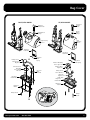
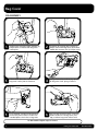
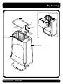
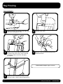
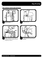
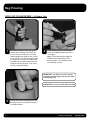
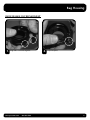
Upright
Service Manual
Table of Contents
ATTENTION
Before servicing any part or
proceeding with any repair
procedure on any ProTeam vacuum,
ALWAYS disconnect the vacuum
from power source.
BAG COVER
Index ...................................................................................................... 2
Disassembly ............................................................................................ 3
BAG HOUSING
Index ......................................................................................................
Disassembly ............................................................................................
Bag Lockout Switch Replacement ...........................................................
Hose Cap Collar Repair ...........................................................................
Quick Release Clip Replacement .............................................................
Bag Housing to Motor Housing Assembly...............................................
4
5
6
7
8
9
MOTOR HOUSING
Index .................................................................................................... 10
Disassembly ..................................................................................... 11-14
Wand Guide ......................................................................................... 15
ELECTRICAL
Wire Harness Replacement .............................................................. 16-23
MOTOR
Carbon Brushes .................................................................................... 24
POWER NOZZLE
Index ....................................................................................................
Assembly ..............................................................................................
Power Nozzle to Body Assembly ...........................................................
Hose Sleeve Replacement .....................................................................
Pivot Bearing Replacement/Wheel Replacement ...................................
Detent Spring Replacement ..................................................................
25
26
27
28
29
30
HOSE AND POWER CORD
Index .................................................................................................... 31
HANDLE
Index .................................................................................................... 32
Assembly ......................................................................................... 33-35
Handle/New Power Cord & Strain Relief Replacement .................... 36-37
Handle and Power Cord Installation ..................................................... 38
Impact Bumper Installation ................................................................... 39
FINAL VACUUM
Assembly .............................................................................................. 40
View Upright Vacuum
Wiring Schematic
at www.pro-team.com
TROUBLESHOOTING
Clearing Hose and Wand Obstructions ............................................ 41-42
www.pro-team.com
866.888.2168
Bag Cover
BASE/HEPA MODEL
XP/HEPA MODEL
Bag Cover
Release
Latch
Bag Cover
Release Latch
Release
Button
Springs
Release Button
Springs
Bag
Housing
Cover
Bag Housing
Cover
Bag Cover
Latch Plate
Bag Cover
Latch Plate
Bag Cover
Latch
Spring
Phillips Screws
Duct Crossover
Bag Cover
Transition Duct/Bag
Cover Upper Seal
Bag Cover
Latch Spring
Transition Duct
Bag Cover
Lower Crossover
Duct/Bag
Cover Nozzle
Plate Seal
Crossover
Duct
Inlet Seal
Phillips Screws
Lower Transition
Duct Seal
Bag Cover
Nozzle Plate
Bag Cover
Nozzle Plate
Bag Cover
Nozzle Plate
Bag Cover
Gasket
Bag Cover
Gasket
Phillips Screws
Phillips
Screws
BOTTOM VIEW
www.pro-team.com
866.888.2168
2
Bag Cover
DISASSEMBLY
1.
Tilt bag cover forward to open. Remove (4)
Phillips screws to release from bag cover
nozzle plate.
2.
To release XP transition duct remove (2)
Phillips screws from bag cover nozzle. Base
model duct crossover has (4) Phillips screws.
3.
Lift transition duct/duct crossover from
bag cover nozzle plate and remove.
4.
Using a flathead screwdriver pry upward
on bag cover latch spring to release.
5.
Insert flathead screwdriver beneath bag
cover latch plate to release. Make sure
rounded points clear holes in bag cover.
6.
Using thumb to hold in place, insert flathead screwdriver into bag cover (near
top) to release bag cover release latch.
To Reassemble. Repeat steps in reverse.
3
www.pro-team.com
866.888.2168
Bag Housing
Completed Bag Housing
Bag Housing Seal Gasket
Phillips Screw
Handle
Nut Plate
Filter Lock-Out
Cover Switch
Filter
Lock-Out
Switch
Rivet for Bag
Housing Assembly
Bag Housing Assembly with Riveted Hinge and
Bag Cover Nozzle Plate
www.pro-team.com
866.888.2168
4
Bag Housing
DISASSEMBLY
1.
Remove screw on carry handle. Slide tube away
from base. Unplug power cord.
2.
Remove cover screw.
3.
Remove switch cover and filter lockout switch.
To remove the switch cover, insert a flathead
screwdriver under switch lever and gently
pry upward.
4.
Remove crimps by pressing locking tab on
locked connector.
To Reassemble. Repeat steps in reverse.
5.
5
Remove 4 screws located near bottom of bag
housing (2 front, 2 back). Remove bag housing.
www.pro-team.com
866.888.2168
Bag Housing
BAG LOCKOUT SWITCH REPLACEMENT
1.
Open filter bag housing.
Remove filter bag.
2.
Remove cover screw.
3.
Remove switch cover and filter lockout
switch. To remove the switch cover, insert
a flathead screwdriver under switch lever
and gently pry upward.
4.
Remove crimps by pressing locking tab
on locked connectors. Reverse steps to
reassemble.
www.pro-team.com
866.888.2168
6
Bag Housing
HOSE CAP COLLAR REPAIR – XP Models Only
1.
To inspect the collar, attach the quick
release cuff to the bag cover collar. Lift
the vacuum by the hose cuff. The collar
should support the weight of the vacuum.
If not, the collar will fail and separate from
the bag cover. The collar will need to be
removed from the quick release cuff and
re-glued into the bag cover. If this collar
test fails, Proceed to Step 2.
2.
Clean the quick release cuff and bag
cover with rubbing alcohol to ensure a
secure grip.
Apply a continuous bead of adhesive*
around the entire perimeter of the
detached collar. Care should be taken
to avoid drips and runs.
IMPORTANT: you have only a few seconds
to apply the bead of glue and seat the collar
into the bag cover.
*IMPORTANT: use only Loctite adhesive #454.
3.
7
Quickly insert collar into bag cover evenly,
pressing firmly for 20 seconds to ensure
an adequate bond.
www.pro-team.com
866.888.2168
Bag Housing
QUICK RELEASE CLIP REPLACEMENT
1.
Aligh tabs. Push ends together.
www.pro-team.com
866.888.2168
2.
Snap into place.
8
Bag Housing to Motor Housing
ASSEMBLY
(a) Feed bag switch wires through bag housing.
(b) Align duct with opening in bag housing
(APPLIES TO XP MODELS ONLY).
Bag Housing Cover
(c) Bag housing assembly should fit neatly
onto bulkhead.
(d) Insert bag housing screws and tighten.
Switch Cover
Phillips Screw
(e) Attach harness connectors to switch and place
switch into position.
Filter Lock-Out
Switch Cover
Bag Housing
Gasket Seal
(f) Fasten switch cover with screw.
(d)
(f)
(g) If replacing the bag housing seal, do not let the
seal cover the lockout switch cover opening.
Handle Nut Plate
Filter Lock-Out
Switch
NOTE: Make sure the handle nut plate is in place before
you replace the bag housing gasket seal.
(e)
Bag Housing
Assembly
(a)
(d)
(d)
(d)
Left/Right Wand Guide or
(both) Duct Assembly
APPLIES TO
XP MODELS ONLY
(b)
(c)
Motor Housing
9
www.pro-team.com
866.888.2168
Motor Housing
APPLIES TO
XP MODELS ONLY
Completed
Motor Housing
Completed
Motor Housing
APPLIES TO
XP MODELS
ONLY
BASE MODEL
HEPA MODEL
Bulkhead
Phillips Screw for Wand Guide
Upper
Motor
Mount
Motor
(Includes
Wires)
Lower
Motor Mount
Lower
Air Duct
Phillips Screw
Left Panel
Motor Housing
Sound Foam
Front Panel
Motor Housing
Sound Foam
Upper Left Wand Guide
APPLIES TO XP MODELS ONLY
Upper Right Wand
Guide APPLIES TO
XP MODELS ONLY
A. Main Power
Supply Harness
(105754 Wire
Harness Kit
Includes A-D)
Wand
Lockout
Switch
Lower
Air Duct
Seal
C. Bag Full
Indicator
Sensor
Air Duct
Assembly
B. Jumper
Harness
Rear Panel Motor
Housing
Sound Foam
Motor
Housing
High Filtration
Filter Exhaust
E. Power
Nozzle
Switch
Harness
Rear Wheel
Motor
Housing
Pivot Bearing
Filter Cartridge Cover
Pivot
Bearing
D. Power Nozzle
Switch Harness
HEPA Media
Exhaust Filter
Rear Wheel
Filter Cartridge Cover
www.pro-team.com
866.888.2168
10
Motor Housing
DISASSEMBLY
1.
Remove handle and power cord. Open bag housing
cover. Remove Intercept Micro® Filter.
2.
Remove switch cover screw.
3.
Remove switch cover and filter lockout switch.
To remove the switch cover, insert a flathead screwdriver under switch lever and gently pry upward.
4.
Remove crimps by pressing locking tab on
connector.
(Continued on page 12)
11
www.pro-team.com
866.888.2168
Motor Housing
DISASSEMBLY
(CONTINUED FROM PAGE 11)
5.
Remove (4) bag housing screws and bag housing.
6.
Remove the bag full indicator tube (tube not
pictured) from the bulkhead and lift off the
bulkhead.
7.
Remove upper motor mount. Lift motor from
housing.
8.
Disconnect motor crimps from motor and from
lower air duct. Remove motor.
(Continued on page 13)
www.pro-team.com
866.888.2168
12
Motor Housing
DISASSEMBLY
9.
11.
(CONTINUED FROM PAGE 12)
Remove (2) lower air duct screws from inside
motor housing then remove the foam that covers
wire harness.
10.
Housing should look like this after the foam and
air duct are removed.
Turn vacuum over and remove (8) screws.
12.
Slide duct flex hose from powerhead.
(Continued on page 14)
13
www.pro-team.com
866.888.2168
Motor Housing
DISASSEMBLY
13.
(CONTINUED FROM PAGE 13)
Remove (2) wheel clamp screws on left and
right wheels.
14.
Remove wheels and pivot bearings.
Pull wire harness through body housing.
To Reassemble. Repeat steps in reverse.
15. Remove exhaust filter.
www.pro-team.com
866.888.2168
14
Motor Housing
WAND GUIDE – For XP Models Only
Note: Use care in prying open latches with
screwdriver so as not to break tabs.
Unsnap latches closest
to fingers first
1.
Separate left wand guide from right wand guide by
inserting two fingers between two guides. Use a flat tip
screwdriver with opposite hand to unsnap lock latches
and pry open wand guides using your two fingers.
Left Wand Guide
Lock Latches
Right Wand Guide
Latch Hole
Switch
Guide Latch
2.
15
Switch Installation. Seat switch into the left wand
guide. Snap lock latches together all the way up
both sides of the wand guides.
www.pro-team.com
866.888.2168
Wire Harness
WIRE HARNESS REPLACEMENT
1.
Remove handle and power cord. Open bag housing
cover. Remove Intercept Micro Filter.
2.
Remove switch cover screw.
3.
Remove switch cover and filter lockout switch.
To remove the switch cover, insert a flathead
screwdriver under switch lever and gently pry
upward.
4.
Remove crimps by pressing locking tab
on connector.
www.pro-team.com
866.888.2168
(Continued on page 17)
16
Wire Harness
WIRE HARNESS REPLACEMENT (CONTINUED FROM PAGE 16)
5.
Remove (4) bag housing screws and remove
bag housing.
6.
Remove the bag full indicator tube (tube not pictured) from the bulkhead and lift off the bulkhead.
7.
Remove upper motor mount.
8.
Disconnect motor crimps from motor and
remove motor.
(Continued on page 18)
17
www.pro-team.com
866.888.2168
Wire Harness
WIRE HARNESS REPLACEMENT (CONTINUED FROM PAGE 17)
9.
Remove (2) lower air duct screws from inside
motor housing then remove the foam that covers
wire harness.
10.
Cut lower wire harness between the motor housing
and the base assembly. Pull the air duct system,
air duct hose and lower wire harness out of the
motor housing.
Note: Rotate brass fitting so it cannot be trapped
by the lower duct.
11.
Insert new power nozzle wire harness in
motor housing, locking brass fitting into
position as shown.
www.pro-team.com
866.888.2168
(Continued on page 19)
18
Wire Harness
WIRE HARNESS REPLACEMENT (CONTINUED FROM PAGE 18)
lower duct assembly and foam. Tighten (2)
12. Install
screws. Wire harness should remain behind lower
13.
Install upper wire harness and connect the vacuum
bag full sensor.
15.
Replace vacuum motor as shown.
duct assembly. Reinstall foam as shown.
RED
14.
WHITE
Connect wires as shown – Red to red. White to
white.
Note: The two black wires are threaded up
through the wand guide.
Note: motor must be properly seated. It is
properly seated when the motor can no longer rotate easily. The bulkhead will not fully
seat over the motor housing if the motor is
not properly installed.
(Continued on page 20)
19
www.pro-team.com
866.888.2168
Wire Harness
WIRE HARNESS REPLACEMENT (CONTINUED FROM PAGE 19)
16.
Replace sound foam and install the motor mount.
18.
Pull wires up through housing – one on each side.
17.
19.
Tuck wires below bulkhead, leaving the bag full
indicator tube out to insert into the bulkhead as
shown. If the bulkhead does not seat firmly onto
the motor housing, you must adjust the motor
until the motor is properly installed.
Reinstall bag lockout switch.
(Continued on page 21)
www.pro-team.com
866.888.2168
20
Wire Harness
WIRE HARNESS REPLACEMENT (CONTINUED FROM PAGE 20)
20.
Attach bag housing. Insert (4) bag housing screws.
Upper wire harness replacement now complete.
22. Disconnect all wire connections.
21.
To replace lower wire harness remove (8)
baseplate screws and turn vacuum back over to
remove base cover.
wire ties. Remove the circuit breaker and
23. Remove
power nozzle lockout switch. Do not remove power
nozzle motor.
*ProCare models do not have a power nozzle
lockout switch.
(Continued on page 22)
21
www.pro-team.com
866.888.2168
Wire Harness
WIRE HARNESS REPLACEMENT (CONTINUED FROM PAGE 21)
24. Remove screw that holds the cover and air duct.
25.
Thread the air duct hose into the motor housing,
turning counter clockwise.
WHITE
RED
BLUE
BLACK
the hose sleeve into the other end of the hose
26. Put
and position in the base assembly. Replace the
cover, air duct, and screw.
www.pro-team.com
866.888.2168
27.
Connect wires as shown and verify orientation of
switches.
(Continued on page 23)
22
Wire Harness
WIRE HARNESS REPLACEMENT (CONTINUED FROM PAGE 22)
LOCKOUT
SWITCH ON XP
MODELS ONLY
28. Attach new blue and black wires.
29. Replace base cover and screws.
To Reassemble.
Reverse Steps 29 through 1 to finish reassembly.
TO PERFORM A FUNCTION TEST:
1. Reinstall handle assembly and cord.
2. Install Intercept Micro Filter.
3. Plug in vacuum and turn vacuum on in the number two (II) position.
4. Powerhead motor should be running. Release vacuum from upright locked position.
5. The brush roll motor should stop and the red warning light should light up. Release the switch and the
powerhead should go back to normal operation.
6. Turn the vacuum on in position number one (I). The vacuum motor should be on. Pull out the wand and cover
the end of the wand with your hand. This will simulate blockage and the bag full light should come on. Take
your hand off the end of the wand and the light should turn off. If your vacuum passes these tests, your
vacuum is ready to use.
23
www.pro-team.com
866.888.2168
Motor
REMOVING CARBON BRUSHES
1.
Disconnect wire from carbon
brush.
2.
INSTALLING CARBON BRUSHES
1.
Insert carbon brush into
bracket.
www.pro-team.com
866.888.2168
2.
Remove both locking connectors with small flat tip screwdriver. Press brass tab (inside
bracket) down so it is flush
with brush.
3.
Using pliers (or fingers), carefully
grasp tab and remove carbon
brush from bracket
Carefully bend brass tab slightly
upward with small flat tip
screwdriver.
3.
Re-connect wire. Replace
locking tabs. Bend tabs
downward.
24
Power Nozzle
Fully Assembled Power Nozzle
Upright Lock Detent
Spring
Power
Nozzle
Cover
Circuit Breaker
Brush Retainer
Phillips Screw
Vacuum Operation Indicator Board
Safety Lockout Switch
XP models only
Air Duct Cover
Motor Vibration Grommet
Brush Roll
Retainer
Motor Phillips Screw
14" Brush Roll
Motor
Brush Roll Drive Belt
Air Duct
Base Cover Seal
Formed Wire Brace
Lower Hose to Air Duct
Air Duct Hose Sleeve
Phillips Screw
Baseplate
Rear Wheel Clamp
Front Roller
Front Roller
Axle Shaft
Base Cover Phillips Screw
Vinyl Bumper
25
www.pro-team.com
866.888.2168
Power Nozzle
ASSEMBLY
1.
2.
Insert braces.
Install motor, brush roll, and belt. Be careful. Do
not attempt to over-tighten screws.
d
b
a
Fully assembled power nozzle (bottom view).
3.
Additional components:
a) Install sleeve and hose.
b) Install duct cover.
c) Install electronic components, Vacuum Operation Indicator Board, circuit breaker, and power nozzle lockout
switch (lockout switch XP models only – not pictured).
d) Attach jumper wire to Vacuum Operation Indicator Board.
e) Make sure components are properly seated in the base.
www.pro-team.com
866.888.2168
26
Power Nozzle to Body Assembly
ASSEMBLY
1.
Place axle sleeve onto motor axle,
making sure the shoulder is facing
the motor housing. Put wheel
onto motor housing axle.
3.
Flip the unit and fasten cover to power nozzle base using (8) screws.
27
2.
Wheel axles on the motor housing should be placed in the grooves on the
power nozzle base. Wheel clamps are then put into place and screwed
down. Power nozzle cover will then be placed on top of the base.
www.pro-team.com
866.888.2168
Power Nozzle
HOSE SLEEVE REPLACEMENT
1.
Remove (8) screws from base plate. Turn vacuum
over and pull base cover off powerhead.
2.
Unclip circuit board and move aside.
3.
Unscrew air duct cover.
4.
Pull off air duct cover. Pull out hose sleeve.
Replace with new sleeve. Sleeve must sit in groove to
be properly seated. Reverse steps to reassemble.
www.pro-team.com
866.888.2168
28
Power Nozzle
PIVOT BEARING REPLACEMENT/WHEEL REPLACEMENT
1.
Remove 8 screws from base plate.
2.
Turn vacuum over and pull base cover
off powerhead.
3.
Remove right and left rear wheel clamps.
4.
Lift bag housing from powerhead and remove
wheel.
To Reassemble.
Repeat steps in reverse.
5.
29
Remove old pivot bearing. Install new pivot
bearing.
www.pro-team.com
866.888.2168
Power Nozzle
DETENT SPRING REPLACEMENT
1.
Place vacuum on flat surface in unlocked
position exposing detent springs.
2.
Use needle nose pliers to remove detent
spring if there is adequate spring to grab.
3.
If there is not enough detent spring
to remove with pliers use a flat head
screwdriver to pry out broken spring.
4.
Place new detent spring into spring slot in
vacuum power head as shown.
5.
Push down on detent spring until fully
seated.
www.pro-team.com
866.888.2168
30
Hose and Power Cord
WAND AND HOSE APPLY TO
XP MODELS ONLY
Power Cord with Strain Relief
Hose Assembly with Cuffs
Strain Relief Clasp
Handle
Assembly Screw
for XP Model
Quick
Release
Hose Clip
Carry Handle with Tool
Caddy for XP Model
Quick
Release
Hose Cuff
Handle
Assembly Screw
for Base Model
Wand
Carry Handle with Tool
Caddy for Base Model
31
Cord Retention Clip
www.pro-team.com
866.888.2168
Handle
Handle with Over Mold and Decal
On/Off Rocker Switch
Cord Wrap Bracket
Cord Wrap Phillips Screw
Cord Wrap Bracket Compression Spring Washer
Handle Bezel with Screws
(XP version pictured)
Cord Wrap Bracket Compression Spring
Handle Assembly Phillips Screw
Handle Tube with Wire Harness, Rivet Nut and Plug Rivet
Handle Tube Bushing
and Screw
www.pro-team.com
866.888.2168
32
Handle
HANDLE ASSEMBLY
fig. 1
1.
fig. 2
Use a flathead screwdriver (fig. 1) to pry bottom of switch from the handle body. Disconnect all wires from switch
posts by depressing locking tab on base of crimps. (fig. 2)
fig. 3
2.
Remove screw at base of handle and remove from
handle tube (fig. 3).
fig. 4
3.
Feed handle wire harness through new handle and
replace screw at the base of the handle (fig. 4).
(Continued on page 34)
33
www.pro-team.com
866.888.2168
Handle
HANDLE ASSEMBLY
(CONTINUED FROM PAGE 33)
front of switch
I
0
II
position II must be on the bottom
before attaching wires to spades
Feed wires through opening on handle bezel.
short
brown
long
blue
Using the diagram provided above, attach wires to
switch. Orient the switch box with the II
position on the down side.
a) Attach the first plug on the brown wire to the
middle left spade.
b) Attach the first plug on the blue wire to the
lowest left spade. Wait to attach the last
blue plug.
c) Wrap the second brown plug underneath blue
and attach to the middle right spade.
d) Attach the last blue plug to the upper
right spade. The bottom right spade will
remain unattached.
e) Connect the red wire to the top right spade.
B
BR
When finished with steps a) through e) your final
wire connection configuration should appear
as above.
www.pro-team.com
long
brown
O
WN
B
N
BROWN BROWN
6.
W
RO
UE
red
LUE
RED
ED
RED R
RED RED
BL
5.
short
blue
BLUE
4.
back of switch
866.888.2168
Install the switch into the handle bezel. Place the long
BLUE, BROWN, then RED wires between the screw bosses
in that order (as shown). BROWN and BLUE wire loops
must be positioned above the screw bosses on the handle
bezel as shown.
(Continued on page 35)
34
Handle
HANDLE ASSEMBLY
7.
(CONTINUED FROM PAGE 34)
Switch must remain flat to the handle bezel when
installed into handle body as shown.
8.
Press the switch into place in the handle bezel.
The II position should be closest to the front of
the bezel.
A
9.
Lay the long red, brown and blue wires between
the circular shoulders and gently place handle
bezel into handle.
10.
B
Slide tab A into handle slot B and press firmly
into place at C. Be sure all switch wires are routed
between screw bosses to ensure that the wires do
not get damaged. Insert screws into bezel (fig. 5).
fig. 5
C
35
www.pro-team.com
866.888.2168
Handle and Power Cord
NEW CORD AND STRAIN RELIEF REPLACEMENT
1.
Use a flathead screwdriver and hammer to push the
strain relief towards the handle. Snap off remaining
strain relief.
2.
Remove screw from carry handle and remove carry
handle.
4.
Feed new strain relief clasp over the new power
cord. Slide strain relief up to the groove on the
power cord and snap strain relief clasp into place.
Cord Retension Clip
3.
Unscrew cord retension clip and set aside. Slide
handle tube away from base. Unplug old power
cord.
NOTE: Use care when sliding the strain relief clasp
over the handle tube bushing so as not to damage
bushing.
(Continued on page 37)
www.pro-team.com
866.888.2168
36
Handle and Power Cord
NEW CORD AND STRAIN RELIEF REPLACEMENT
5.
Slide handle tube through opening in strain relief.
Align holes on strain relief and handle tube.
Insert new ratchet fastener in hole and push flush.
7.
Use flathead screwdriver to reattach carry handle
to handle tube. Ensure proper alignment of carry
handle by verifying bag cover closure.
37
6.
(CONTINUED FROM PAGE 36)
Plug in new cord and slide handle tube into handle
sleeve on motor housing. Press firmly down on handle to ensure it is fully seated. Install cord retension
clip next to power cord. Install screw and tighten.
www.pro-team.com
866.888.2168
Handle and Power Cord
HANDLE INSTALLATION
1.
Insert the handle tube into the channel on the bag
housing and press downward until it is 2-3 inches
inside the channel. It will be correctly inserted
when the handle bushing hole in the handle tube
aligns with the nut plate hole in the bag housing.
2.
Insert ratchet fastener into cord clasp opening by
pushing with thumb to connect cord to handle.
3.
www.pro-team.com
866.888.2168
38
Handle
IMPACT BUMPER INSTALLATION
Old Washer
1.
Using a Phillips Head screwdriver, remove screw
from cord wrap bracket. Discard screw only.
3.
Insert impact bumper assembly into cord wrap
bracket.
Note: Screw should be inserted inside spring from
original assembly. Do not over tighten.
39
2.
Place new washer on new screw and insert into impact
bumper. Place old washer on end of screw.
Note: Make sure spring is installed as shown above.
www.pro-team.com
866.888.2168
Final Vacuum Assembly
ASSEMBLY
Hose Assembly with Cuffs
1.
Install all 3 filters:
(a) Intercept Micro Filter
(b) Motor Intake Filter
(c) Exhaust Filter
2.
Install Power Cord and Handle with
Over Mold and Decal.
Attach with Handle Tube Bushing and
Carry Handle with Tool Caddy.
WAND AND HOSE APPLY TO
XP MODELS ONLY
Handle with Over
Mold and Decal
Quick
Release
Hose
Cuff
3.
Wrap Power Cord around
Cord Wrap Post.
Cord Wrap
Screw
Wand
Power Cord
Handle
Tube
Bushing
Handle
Assembly
Screw
(a)
Carry Handle
with
Tool Caddy
(b)
Cord Wrap Post
(c)
www.pro-team.com
866.888.2168
40
Troubleshooting
CLEARING HOSE AND WAND OBSTRUCTIONS – XP MODELS
RE
E T
E T
S
RE
S
CLEARING THE BRUSH ROLL
Obstructions such as hair, string, and throw rugs may cause the red brush indicator light to be illuminated and the power nozzle to shut off.
Turn off vacuum and unplug power cord from outlet.
1.
2.
On underside of vacuum, pull out, or cut away, obstructions on the brush
roll. (Figure A)
3.
Press the reset button on top side of powerhead. Plug-in power cord, and
restart motor (Figure A).
Figure A
Airflow path and possible
obstruction locations
FIG.
1
CLEARING HOSE & WAND
Obstructions in hoses and wands may reduce or eliminate suction.
Quick
release
tabs
FIG. 2
FIG. 3
Lower air duct
Figure B
Wand
opening
1.
Familiarize yourself with air flow path and possible obstruction locations
(Figure B).
2.
To determine obstruction location, remove wand from port. (Figure C). Turn
on vacuum and place hand over wand opening to check for proper suction.
If no suction exists, blockage is at location A or B (as shown in Figure B) and
proceed to Step 3. If there is proper suction, the blockage is at location C or
D (as shown in Figure B) and proceed to Step 5.
3.
Open Bag Housing Cover (FIG. 1) and replace Intercept Micro Filter. A full
filter will restrict airflow.
4.
Remove hose from the bag housing cover by using the quick release tabs.
(FIG. 2). Look into upper hose and wand. Shake or insert broom handle to
clear any visible debris. Replace hose and wand on vacuum.
5.
If blockage is not in the wand or upper hose, disconnect the lower air duct
hose on the back of the power nozzle (FIG 3). Visually check the lower air
duct hose for debris and remove. To check for unobstructed air flow, turn
on vacuum and place hand over opening on lower air duct. If you feel
proper suction, reconnect lower air duct and resume vacuuming. If blockage
is not in lower air duct hose, proceed to step 6.
6.
With bottom air duct hose and upper hose and wand disconnected, carefully
insert a broom handle (or any similar item like a short length of hose, pipe,
etc) approximately 14 inches into wand guide on top of vacuum housing
(Figure D) to dislodge obstruction or debris. Debris should then drop or move
into the lower air duct hose where you can then remove it with your hand
(FIG 3).
Wand
port
Wand
guide
Wand
port
Lower
air duct
Figure C
41
Figure D
7.
Reconnect the lower air duct hose and upper hose assembly, and turn on
the vacuum.
www.pro-team.com
866.888.2168
Troubleshooting
CLEARING HOSE AND WAND OBSTRUCTIONS – HEPA MODELS
CLEARING THE BRUSH ROLL
RE
S
E T
RE
S
E T
Figure A
Obstructions such as hair, string, and throw rugs may cause the red brush
indicator light to be illuminated and the power nozzle to shut off.
Turn off vacuum and unplug power cord from outlet.
1.
2.
On underside of vacuum, pull out, or cut away, obstructions on the
brush roll. (Figure A).
3.
Press the reset button on top side of powerhead. Plug-in power cord,
and restart motor. (Figure A).
CLEARING HOSE & WAND
Obstructions in hoses and wands may reduce or eliminate suction.
Figure B
Figure C
1.
Turn off vacuum and unplug power cord from outlet
2.
Open Bag Housing Cover (Figure B) and replace Intercept Micro Filter. A
full filter will restrict airflow.
3.
Disconnect the lower air duct hose on the back of the power nozzle
(Figure C). Visually check the lower air duct hose for debris and remove.
4.
To check for unobstructed air flow, turn on vacuum with bag housing
cover closed and place hand over opening on lower air duct (Figure C). If
you feel prope suction, reconnect lower air duct and resume vacuuming.
If blockage is not in lower air duct hose, proceed to step 5.
5.
Carefully insert a broom handle (or any similar item like a short length of
hose, pipe, etc ) approximately 14 inches into guide on top of vacuum
housing (Figure D) to dislodge obstruction or debris. Debris should then
drop or move into the lower air duct where you can then remove it with
your hand.
6.
Reconnect the lower air duct and upper hose assembly. Close bag housing cover and power on the vacuum.
Port
Guide
Lower air duct
Figure D
www.pro-team.com
866.888.2168
42
P.O. Box 7385, Boise, Idaho 83707 • 866.888.2168
www.pro-team.com
#106243 Revised 12/12