1
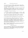
Soft Serve Freezer
\
SINGLE FLAVOR COUNTER MODEL UC-71G
OPERNION and SERVICE
MANUAL
COLDELITE CORPORATION OF AMERICA
3760 INDUSTRIAL DR.
WINSTON-SALEM, N.C. 27105
TEL(919) 661-9893
FAX (9.19) 661-9895
I N D E X
Page
PART I
INSTALLATION
A) Uncrating
B) Electrical Requirements
C ) Electrical Connections
PART I1
EXPLANATION OF ELECTRICAL CONTROLS
A) Selector Switch
B ) Control Box
C ) Other Controls
PART I11
INITIAL CLEANING PROCEDURE
Assembly of Freezer
Head Assembly - Diagram
Sanitizing the Freezer
PART IV
STARTING THE FREEZER
Accessories for Model UC-71G
Routine, Periodic Cleaning Procedures
PART V
TECHNICAL INFORMATION
A) Refrigeration
Adjusting Product Temperature
How to Adjust Rear Micro Switch
Hard-0-Matic Springs
WARNING
Energy Conservation
Mix Tank Refrigeration
B) Drive System
Spigot Switch - How It Ogerates
How to Adjust Front Micro Switch
Gravity Feed Valve - How to Operate
How to Adjust Gravity Feed Valve
MAINTENANCE
WARNING
TROUBLE SHOOTING GUIDE
APPENDIX - Figures 1 to 10
FOREWORD
Thank you for selecting COLDELITE to meet today's fast growing demands. Your
COLDELITE freezer has been manufactured at the most modern freezer manufacturing plant
in the U.S. A., our Winston Salem, N.C., facility, utilizing the most advanced equipment
and technology available in the industry. We, at Coldelite, take great pride and care in the
manufacture of each and every freezer, using only the finest components available, to
provide you with years of trouble-free operation.
Over twenty-five years of experience in the manufacturing of dispensing equipment have
guided us in the preparation of this Operation and Service Manual. PLEASE READ IT
CAREFULLY, Keep it for future reference and most of all, follow the instructions from the
very time your machine is delivered.
On the following pages, you will find important information and procedures which
describe the proper installation, sanitizing, operation and maintenance of your COLDELITE
machine. We feel certain that your full compliance with these instructions will assure you
of excellent performance, trouble-free operation and a profitable business for years to
come.
NOTICE
Failure to closely follow set-up and maintenance procedures can void your warranty.
Coldelite Corporation will not be responsible for any machine not properly maintained.
In the event this unit should malfunction, please contact your Coldelite distributor or an
authorized service agency.
WARNING
EXTREME CARE MUST BE TAKEN WHEN REMOVING SIDE. REAR
OR CONTROL BOX PANELS.
ALWAYS TURN THE SELECTOR SWITCH TO THE OFF POSITION.
ALSO TURN OFF THE DISCONNECT SWITCH ON ELECTRICAL
SUPPLY LINE BEFORE EXPOSING ANY ELECTRICAL CONNECTIONS
AND/OR MOVING PARTS, SUCH AS BELTS, PULLEYS, FAN BLADES
AND BEATER.
I N S T A L L A T I O N
PART I
Before s t a r t i n g t h i s p r o c e d u r e , make s u r e t h e c a r t o n d o e s
n o t show a n y e v i d e n c e of h a v i n g been dropped, tampered w i t h
o r abused i n s u c h a way a s t o i n d i c a t e t h a t i t s c o n t e n t s may
have been damaged i n t r a n s i t .
-
Should t h e o u t s i d e of t h e c a r t o n g i v e any i n d i c a t i o n of p o s s i b l e a h i d d e n damage, s t a t e t h i s on t h e B i l l of
Lading b e f o r e s i g n i n g . C o n t a c t t h e c a r r i e r immediately and
I f t h i s i s n o t done,
r e q u e s t a n i n s p e c t i o n of t h e damage.
you a r e r e s p o n s i b l e and must pay f o r any r e p a i r s r e q u i r e d .
IMPORTANT
A)
UNCRATING
- Proceed a s f o l l o w s :
I. The c a r t o n i s h e l d t o t h e s k i d by s t e e l s t r a p p i n g . When
you c u t t h i s s t r a p p i n g , do it w i t h c a u t i o n , a s it may s p r i n g
Do not force.
out.
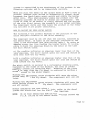
Remove c a r t o n by l i f t i n g it s t r a i g h t up.
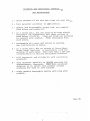
2 . Remove s i n g l e screw a t t h e bottom of each s i d e p a n e l .
Remove p a n e l s by s l i d i n g p a n e l upward s l i g h t l y , t h e n p u l l
outward a t t h e bottom and a l l o w t h e p a n e l t o s l i d e down.
3. The f r e e z e r i s h e l d t o t h e s k i d by a n u t and b o l t on t h e
l e f t and r i g h t s i d e .
Remove t h e s e b o l t s and t h e s k i d .
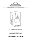
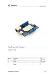
The f r e e z e r i s now r e a d y t o b e p l a c e d on t h e c o u n t e r .
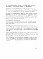
Note t h e i l l u s t r a t i o n s on t h e f o l l o w i n g page.
The c o u n t e r
must b e c a p a b l e of s u p p o r t i n g 2 7 5 l b s . w i t h o u t v i b r a t i o n .
Reinforce i t , i f necessary.
Remember, when choosing a
l o c a t i o n t h a t t h i s u n i t i s a n a i r cooled u n i t and t h e p r o p e r
a i r flow m u s t be m a i n t a i n e d .
Allow a t l e a s t 6 i n c h e s on
e i t h e r s i d e a n d a minimum o f 1 2 i n c h e s between t h e r e a r o f
t h e machine and any o b s t r u c t i o n .
4.
Note: I f t h e s e c l e a r a n c e s are n o t m a i n t a i n e d , t h e p r o d u c t i o n
w i l l be r e d u c e d , c y c l i n g w i l l i n c r e a s e and p o s s i b l y t h e
machine w i l l s t o p c o m p l e t e l y .
I M P O R - T A N T
S a n i t a r y r e g u l a t i o n s r e q u i r e t h a t c o u n t e r model machines be
sealed t o c a b i n e t top.
Apply a c o a t of p r o p e r s e a l i n g compound (RTV 7 3 2 o r e q u i v a l e n t ) t o machine frame b a s e b e f o r e
securing u n i t .
After i n s t a l l a t i o n , excess s e a l e r around
p e r i m e t e r s h o u l d be removed.
Page 2
f
TIS""
--2
4
I
FRONT V I E W UC-71G
SIDE VIEW UC-71 G
R E A R VIEW UC-71G
(B) ELECTRICAL REQUIREMENTS
Wiring should be made in accordance with the National
Electrical Code and/or local electrical codes, rules and
regulations.
Voltage
UC-71G
115/1/60
Running Amperage
FLA
-
19.0 Amperes
Fuse Size
30 AMP. MAX.
Power Supply must be adequate to meet requirements at all
times. Voltage fluctuations with the machine in operation
should not exceedL+ 10% of the normal or rated voltage.
Adequate Wiring should be provided with respect to wire size
or gauge. Unless otherwise required by the local Electrical
Code, the same size wire gauge at the machine junction box
should be used for the direct power line. A separate circuit
breaker with adequate fuse protection should be employed.
Page 3
An u n f u s e d d i s c o n n e c t s w i t c h o r a proper s i z e p l u g and
r e c e p t a c l e , c l o s e t o t h e f r e e z e r , i s recommended.
C o l d e l i t e f r e e z e r s a r e provided with protection f o r the
b e a t e r motor.
Should t h e l i n e v o l t a g e drop o r i f t h e r e i s
a s h o r t c i r c u i t , t h e overload protector w i l l automatically
d i s c o n n e c t t h e s t a r t e r and t h e machine w i l l s t o p immediately
s o t h a t no permanent damage c a n be caused t o t h e motor.
To s t a r t t h e f r e e z e r a g a i n , push t h e RESET b u t t o n ( a c c e s s e d
t h r o u g h a h o l e i n t h e r i g h t s i d e p a n e l ) . The h e a t e r must
c o o l down f o r s e v e r a l m i n u t e s b e f o r e t h e RESET w i l l o p e r a t e .
The c o m p r e s s o r i s a l s o i n t e r n a l l y p r o t e c t e d .
I f t h e Klixon
p r o t e c t o r t r i p s due t o an o v e r l o a d t o t h e compressor, t h e
p r o t e c t o r w i l l r e s e t automatically.
( C ) ELECTRICAL CONNECTIONS
A f t e r removing t h e r i g h t s i d e p a n e l , t h e f i e l d w i r i n g box
w i l l b e f o u n d on t h e bottom p l a t e and i s l a b e l e d "Connect
Power L i n e Here".
The power l i n e i s passed t h r o u g h a h o l e , l o c a t e d a t t h e
bottom r i g h t a t t h e r e a r o f t h e machine i n t h e p e d e s t a l ,
t h e n it i s p a s s e d through a h o l e on t h e bottom deck d i r e c t l y
below t h e f i e l d w i r i n g box.
The power l i n e may t h e n be conn e c t e d t o t h e f i e l d w i r i n g box.
Upon c o m p l e t i o n , t h e power
l i n e s h o u l d b e clamped t o s i d e o f c o n t r o l box w i t h t h e clamp
supplied.
I n a l l i n s t a l l a t i o n s , t h e machine must b e . p r o p e r l y grounded.
S i n c e a l l h i g h v o l t a g e components ( c o n t r o l s a r e 2 4 v o l t s )
a r e c o n n e c t e d by means of f l e x i b l e c o n d u i t , a d e q u a t e ground
c o n t i n u i t y i s a s s u r e d by r u n n i n g and f a s t e n i n g a ground l i n e
t o t h e machine j u n c t i o n box ground lug.
A f t e r e l e c t r i c a l c o n n e c t i o n s are completed, check t h e r o t a I t s h o u l d b e c o u n t e r c l o c k w i s e when
t i o n of t h e b e a t e r .
I f checking from t h e r e a r
f a c i n g t h e f r o n t of t h e machine.
of t h e machine, n o t e d i r e c t i o n of arrow on f l y wheel f o r
rotation.
Page 4
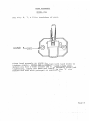
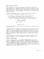
SELECTOR SWITCH
- Fig. A
-
Positions of switch are, as
follows :
OFF
-
- . Machine is off .
AUTO
- This position is used for the production and
dispensing of ice cream, yogurt, etc.
ENERGY
- This position is used for prolonged idle periods.
CONSER-
Product is held at a safe temperature which is
above serving temperature and controlled by a
thermostat. The product may not be served when
in this position. The beatzr motor will operate
whenever the compressor does.
VATION
BEATER
- This position will only activate the beater motor,
(compressor circuits are de-energized) which will
be necessary during the cleaning, sanitizing, and
start-up operation.
Page 5
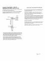
B ) CONTROL BOX
-
located under right side panel and consists
of the following: (See Figure 9)
Compressor Starter
eater
Motor Contactor
Overload Protector - This device senses the current
supplied to the beater motor and will stop the entire
machine in the event of an overload. This device also
houses the reset button.
Transformer - Steps down line voltage to 24 volts to
supply controls.
Thermostat - Controls temperature of the product in the
freezing cylinder when the unit is in the ENERGY CONSERVATION mode.
~imer/TimeDelay - The timer portion of the control will
start the beater motor every 10 minutes when the unit is
in the AUTO mode, allowing the torque control to sense
the consistency of the product. The Time Delay will
delay the start of the compressor 1.5 seconds later than
the beater motor in the AUTO position.
C) OTHER CONTROLS -
.
_
.
:'.
.
1) Solenoid Valve - This valve, located on the left side,
is normally closed. It will open during the compressor
operation.
2) Rear Micro Switch - operates in conjunction with the
Hard-0-Matic to keep the product at the proper consistency.
(For adjustment, See .Part.
V., Paragraph 2. )
3) High Pressure Cut-Out - Located on right side of the
freezer and teed into the discharge line near the compressor; it will cut out the compressor in the event of
a high pressure situation, such as a clogged condenser,
loss of air circulation, etc. {See Figure 9).
NOTE !
CAUTION!
The fan blade is mounted directly to the beater motor
shaft. When cleaning the interior of the machine, ALWAYS
CUT OFF THE MAIN CIRCUIT BREAKER OR TURN OFF THE DISCONNECT SWITCH BEFORE SERVICING THE INSIDE OF THE MACHINE.
THE FAN BLADE WILL BE IN MOTION ANY TIME THE BEATER MOTOR
IS ACTIVATED,
--
Page 6
PART 111 - I N I T I A L CLEANING PROCEDURE
T h i s i s a new machine and it must be completely d i s a s s e m b l e d ,
Proceed, a s f o l l o w s :
washed, a n d s a n i t i z e d b e f o r e s t a r t i n g .
1) Remove mix t a n k c o v e r and i t e m s 5acked i n t h e t a n k ( s p a r e
p a r t s , s a n i t i z e r , l u b r i c a n t , g r a v i t y feed t u b e , e t c . ) ,
2 ) Now remove t h e remaining p a r t s from t h e machine.
Remove
t h e two h a n d knobs h o l d i n g t h e head i n p l a c e .
Then remove
t h e head a s s e m b l y i t s e l f .
P u l l t h e auger o u t of t h e c y l i n d e r .
Make c e r t a i n t h a t t h e l i p s e a l on t h e r e a r of t h e s h a f t i s
removed.
I t i s p o s s i b l e t h a t it may s t i c k t o t h e back of t h e
cylinder,
Take t h e s e p a r t s t o t h e s i n k and wash,
Remove t h e
p i n holding t h e handle i n t h e dispensing plunger.
Remove t h e
h a n d l e and t h e p l u n g e r f o r washing. It i s a d v i s a b l e t o u s e a
d i s h pan t o p u t t h e p a r t s i n s o t h a t no p a r t i s dropped o r
lost.
T h i s s h o u l d be a p l a s t i c pan.
3 ) You now h a v e a l l t h e p a r t s f o r t h e f r e e z e r i n t h e s i n k .
Wash a l l t h e s e p a r t s w i t h a d e t e r g e n t and t h e b r u s h e s s u p p l i e d
DO NOT U S E - H O T - W A T E R ON ANY PLASTIC PARTS.
w i t h t h e machine.
D o not d r y t h e s e p a r t s b u t
Rinse a l l p a r t s i n warm w a t e r .
allow t o a i r dry o r assemble w e t .
ASSEMBLY O F FREEZER - R e v e r s e t h e above p r o c e d u r e .
Install the
a u g e r f i r s t , b e i n g s u r e t h a t t h e l i p s e a l i s on t h e r e a r of t h e
a u g e r and h a s been l u b r i c a t e d on both s i d e s w i t h t h e sample
l u b r i c a n t supplied.
A l l ' 0 ' r i n g s must be l u b r i c a t e d l i g h t l y
with P e t r o g e l o r equivalent.
When r e a s s e m b l i n g t h e f r e e z e r , r e f e r t o t h e i l l u s t r a t i o n s ,
F i g u r e s 6 , 3, and 8 .
CAUTION - I t i s v e r y i m p o r t a n t . t o have t h e i d l e r i n s t a l l e d correctly.
I f n o t done p r o p e r l y , damage can b e caused t o t h e s p i g o t head a s s e m b l y .
Assembly i n s t r u c t i o n s s h o u l d be c a r e f u l l y f o l lowed.
When a s s e m b l i n g t h e i d l e r , f i r s t h o l d it s o t h a t t h e f i n s a r e i n
an u p r i g h t p o s i t i o n .
Then i n s e r t it s o t h a t t h e t h i n n e r p o r t i o n
of t h e i d l e r s h a f t f i t s i n t o t h e grooved s l o t a t t h e f r o n t of t h e
b e a t e r / a u g e r , I t e m #21, F i g . 8.
The grooved s l o t must be f a c i n g
The f r o n t b a r o f t h e i d l e r s h o u l d b e i n a horup a t a l l t i m e s .
izontal position.
Push t h e i d l e r back, i n s e r t i n g i t s s h a f t i n t o
the h o l e - o f t h e b e a t e r / a u g e r s h a f t . I f i n s t a l l e d c o r r e c t l y , t h e
i d l e r , when t u r n e d , s h o u l d r o t a t e f r e e l y and w i l l b e a u t o m a t i c a l l y locked i n place.
I f it d o e s n o t r o t a t e , it i s i n s t a l l e d i n G o t h r o u g h t h e above i n s t r u c t i o n s a g a i n .
correctly.
F i n a l l y , when p r o p e r l y i n s t a l l e d , t h e f r o n t b a r o f - t h e i d l e r
should be i n a v e r t i c a l p o s i t i o n s o t h a t t h e b a r w i l l n o t i n t e r f e r e w i t h t h e two p i n s l o c a t e d i n s i d e t h e s p i g o t h e a d , when t h e
head i s i n s t a l l e d .
See F i g u r e 3 .
Page 7
HEAD ASSEMBLY
MODEL 7 1 G
See F i g .
6, 7,
&
8 f o r breakdown of p a r t s .
HAND KNOBS
P l a c e head a s s e m b l y on s t u d s and t u r n b o t h hand knobs t o
t i g h t e n evenly.
NEVER USE A WRENCH - hand t i g h t o n l y .
Should you h a v e a l e a k around t h e head assembly a f t e r hand
t i g h t e n i n g , remove t h e head and l u b r i c a t e t h e ' 0 ' r i n g
behind t h e head with p e t r o g e l o r equivalent.
Page .8
SANITIZING THE FREEZER
The freezer is now washed and reassembled. The next step
is to sanitize the machine which is most important. This
procedure will retard the growth of bacteria and insure
excellent tests on your product when examined by the
Sanitation and/or Department of Agriculture.
First, mix the sanitizer in a clean pail. Hot water first,
to dissolve the powder, and then cold water. Instructions
are on the sample sanitizer that is included with the
machine. Usually two tablespoons to two gallons of water
will give you a solution of 200 ppm chlorine, which is sufficient to kill the bacteria. Do not exceed the formula as
it does not add to its effectiveness.
OFF position, pour one
With the selector switch.in the gallon of sanitizer into the mix tank. Lay the gravity feed
tube in the mix tank so that it is covered with the sanitizing solution. Now turn the selector switch to BEATER for
only a few seconds.
The sanitizer will now run freely into the cylinder. Simply
place a bucket or drain attachment under the head and allow
the sanitizer to run out. During this operation, the selector switch is in the OFF position.
We recommend that the auger/beater be turned as little as
possible during the washing and sanitizing operations. In
the last phase, you can turn the selector switch to BEATER
for two or three seconds to help remove the last of the
sanitizer.
For sanitary reasons, the plastic cover on top of the mix
tank should be removed only for the time strictly necessary
to make the desired adjustments.
Page 8a
CLEANING AND SANITIZIKG INSTRUCTIONS
NSF REGULATIONS
1
-
D r a i n machine of a l l mix and r i n s e w i t h c o o l w a t e r .
2
-
Turn s e l e c t o r switch ( s ) t o OFF p o s i t i o n .
3
-
Remove and d i s a s s e m b l e s p i g o t head, mix pump(s) ,
f e e d elbow and b e a t e r f s )
4
-
I n a c l e a n p a i l , mix one ounce of Nu-Foam Liquid
Detergent (or equivalent) with three gallons of
warm w a t e r (70-80°F). Clean and brush a l l s u r f a c e s
i n c o n t a c t with product.
F l u s h thoroughly w i t h
warm w a t e r .
.
5 - Reassemble a l l p a r t s and i n s t a l l on machine.
See i n s t r u c t i o n s i n manual.
6
-
I n a c l e a n p a i l , mix two ounces of Stera-Sheen
Green L a b e l S a n i t i z e r ( o r e q u i v a l e n t ) w i t h two
T h i s w i l l make a 2 0 0 ppm
g a l l o n s o f warm w a t e r .
c o n c e n t r a t i o n of c h l o r i n e s a n i t i z i n g s o l u t i o n .
7
-
F i l l h o p p e r ( s ) and c y l i n d e r ( s ) w i t h s a n i t i z i n g
solution.
8
-
Turn s e l e c t o r s w i t c h ( s ) t o BEATER p o s i t i o n f o r
Make s u r e s a n i t i z e r
a p p r o x i m a t e l y 3 0 seconds.
s o l u t i o n i s i n contact with product contact
s u r f a c e s f o r t h r e e t o f i v e minutes.
9
-
D r a i n machine t h o r o u g h l y b e f o r e r e f i l l i n g w i t h
product.
Page 8b
PART I V
The Model UC-71G
STARTING THE FREEZER
i s now s a n i t i z e d and r e a d.y f o r prod1
S t a r t t h e machine, as follows:
1) I n s e r t t h e g r a v i t y f e e d t u b e i n t h e mix t a n k .
Pour a t
l e a s t o n e g a l l o n o f l i q u i d mix i n t o t h e mix t a n k .
The
maximum c a p a c i t y o f t h e h o p p e r i s two g a l l o n s .
Never l o a d
mix above t h e t o p o f t h e f e e d i n g t u b e .
See Page 1 4 .
Turn t h e s e l e c t o r s w i t c h t o BEATER and a l l o w t h e machine t o
r u n a few s e c o n d s .
P l a c e a p a i l o r cup u n d e r t h e d i s p e n s i n g
n o z z l e , o p e n t h e d i s p e n s i n g p l u n g e r and l e t t h e mix push o u t
any s a n i t i z e r l e f t i n t h e c y l i n d e r . When p u r e mix comes o u t
o f t h e h e a d , c l o s e t h e p l u n g e r and a l l o w t h e machine t o cont i n u e t o r u n w i t h t h e s w i t c h i n t h e BEATER p o s i t i o n f o r o n e
minute.
2 ) Now t u r n t h e s e l e c t o r s w i t c h t o AUTO.
This activates t h e
Then
torque c o n t r o l t o sense t h a t refrigeration is required.
s i m p l y a l l o w t h e machine t o r u n u n t i l i t g o e s o f f a u t o m a t i c a l l y .
3 ) You a r e now r e a d y t o draw a f i n i s h e d p r o d u c t .
Pull the
d i s p e n s i n g h a n d l e down s l o w l y u n t i l t h e p r o d u c t comes o u t .
The f r e e z e r i s now i n t h e normal o p e r a t i n g p o s i t i o n .
Be s u r e
t o add mix when n e c e s s a r y , and sim?ly d i s p e n s e t h e p r o d u c t ,
as r e q u i r e d .
4 ) P r o d u c t i o n o f t h e machine i s 4 g a l l o n s p e r h o u r ( c a l c u l a t e d a t 4 0 % o v e r r u n ) or 2-3 c o n e s p e r m i n u t e ( 4 - 5 o z . volume
per cone).
ACCESSORIES FOR THE MODEL UC-71G
A d r a i n a t t a c h m e n t f o r t h e d i s p e n s i n g h e a d , which c o n s i s t s o f
a w a t e r t i g h t c o n n e c t i o n t o t h e head a s s e m b l y , and a h o s e t o
d i r e c t t h e w a s t e water to a suitable drain, during t h e cleaning
operation.
T h i s d r a i n must b e lower t h a n t h e s p i g o t head ( p r e f e r a b l y a
f l o o r d r a i n ) a s t h e w a t e r must f l o w o u t o f t h e machine.
Page 9
ROUTINE,
P E R I O D I C CLEANING PROCEDURES
C l e a n i n g and s a n i t i z i n g s c h e d u l e s a r e
o r l o c a l r e g u l a t o r y a g e n c i e s and must
A w e l l planned cleaning schedule w i l l
w a s t e of t i m e and p r o d u c t w i t h i n your
governed b y your s t a t e
be f o l l o w e d a c c o r d i n g l y .
eliminate excessive
organization.
On a d e s i g n a t e d day ( s ) of t h e week, run t h e mix i n t h e mix
t a n k a s low as f e a s i b l e .
P r o c e e d t o c l e a n t h e machine, as follows:
1) Turn t h e S e l e c t o r Switch t o BEATER p o s i t i o n and l e t t h e
machine r u n f o r 4 t o 5 m i n u t e s .
This w i l l s o f t e n t h e p r o d u c t
i n t h e c y l i n d e r and a l l o w t h e remaining p r o d u c t t o be r e moved more e a s i l y .
2 ) P l a c e a c o n t a i n e r o r b u c k e t under t h e s p i g o t head.
Slowly
p u l l t h e h a n d l e down and remove remaining p r o d u c t from t h e
cylinder.
3 ) When t h e p r o d u c t h a s s t o p p e d flowing, t u r n t h e S e l e c t o r
Switch t o t h e OFF position,
Close the s p i g o t handle.
(See
P a r t 111 - I n i t i a l C l e a n i n g P r o c e d u r e . )
4 ) F i l l t h e mix t a n k w i t h lukewarm water and t u r n t h e S e l e c t o r
Turn S e l e c Switch t o t h e BEATER p o s i t i o n f o r 2 t o 3 Seconds
O F F p o s i t i o n and d r a i n o f f w a t e r by opening
t o r Switch t o t h e Repeat t h i s p r o c e s s two t o t h r e e t i m e s
t h e s p i g o t handle.
A mild d e t e r u n t i l t h e w a t e r d r a i n e d off i s r e l a t i v e l y c l e a r .
g e n t can b e used i n t h i s r i n s i n g o r flushing process.
.
5 ) Brush m i x t a n k t h o r o u g h l y and d r a i n machine.
Then f l u s h
w i t h a s a n i t i z i n g s o l u t i o n t o remove a l l mix p a r t i c l e s .
6 ) Remove s p i g o t head assembly, b e a t e r and s h a f t s e a l .
t o P a r t I11 - I n i t i a l C l e a n i n g Procedure.
Refer
7 ) Thoroughly c l e a n a l l d i s a s s e m b l e d p a r t s and s u r f a c e s w i t h
a m i l d d e t e r g e n t and t h e n s a n i t i z i n g s o l u t i o n ( r e f e r t o
S a n i t i z i n g The F r e e z e r , Page 8a and Assembling t h e F r e e z e r ,
Page 7 .
Page 10
PART V
TECHNICAL INFORMATION
(A) Refriqeration
Compressor - Hermetic - 1 hp - R 502
Actual Running Amperage - 9.5 - 10.0
Suction Pressure - 22 psig
Discharge Pressure - 245 psig @ 72°F ambient
Cooling System - Air
Use of R 502 only - 1.5 lbs.
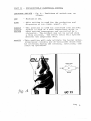
1) ADJUSTING PRODUCT TEMPERATURE - Coldelite uses a
Hard-0-Matic system (patented) which is referred to as g .
This mechanical device controls the refrigeration system for
the freezing cylinder by 'sensing' the consistency or hardness
of the product inside the freezing cylinder. No thermostats
are used in this system.
Basically, the HON control consists of a clutch assembly
The inclines of a disc, fastened to the fly wheel,
(Fig. 2 ) .
are engaged to the inclines of another disc which in turn
rotates the auger.
A set of springs, properly calibrated and radially located
around the fly whee1,'maintains the two discs engaged by
exerting a certai-npressure.
With the gradual hardening of the product inside the freezing
cylinder, a certain resistance or drag will be exerted on the
auger by the product itself.
The disc, rotating the auger, will also be affected by this
drag and will start sliding on the inclines of the other disc,
overcoming the pressure of the springs.
The gradual separation of the two discs, as a result of the
sliding of the inclined surfaces of one disc against the other
will move the complete drive assembly toward the rear of the
machine.
By the time the product has reached the proper consistency or
hardness, the drive assembly will have moved backwards just
enough to open a normally closed micro switch fastened to the
support on the rear frame of the machine.
The opening of this micro switch will de-energize the coil of
the compressor contactor, which will immediately stop the beater
motor and compressor simultaneously. Thus the refrigeration
Page 11
s y s t e m i s c o n t r o l l e d by t h e c o n s i s t e n c y o f t h e product i n t h e
f r e e z i n g c y l i n d e r and n o t by t e m p e r a t u r e c o n t r o l s .
When you p u l l t h e h a n d l e on t h e s p i g o t head t o draw a cone o r
p o r t i o n , a n o t h e r m i c r o s w i t c h i s a u t o m a t i c a l l y c l o s e d , which
b y p a s s e s t h e Hard-0-Matic micro switch and s t a r t s t h e b e a t e r
motor o n l y .
T h i s s i m u l t a n e o u s l y pumps new p r o d u c t i n t o t h e
The
f r e e z i n g c y l i n d e r and s t a r t s t o change i t s c o n s i s t e n c y .
f o r c e o r d r a g on t h e b e a t e r i s slowly r e d u c e d and t h e s p r i n g s
o f t h e s l i p c l u t c h r e t u r n t h e assembly t o i t s normal p o s i t i o n .
The compressor s t a r t s and t h u s keeps t h e p r o d u c t i n t h e f r e e z i n g c y l i n d e r a t t h e proper consistency.
HOW TO A D J U S T THE REAR MICRO SWITCH
The f i r m n e s s o f t h e p r o d u c t depends on t h e p o s i t i o n of t h e
m i c r o s w i t c h i n r e l a t i o n t o t h e d r i v e assembly.
The compressor must be c u t o f f when t h e c u r r e n t , absorbed b y
t h e b e a t e r m o t o r , i s e q u a l t o t h e amperage i n d i c a t e d on t h e
l a b e l i n t h e e l e c t r i c a l box (B/M Cut-Out Amps.)
By u s i n g a n
ammeter a c r o s s t h e l i n e f e e d i n g t h e b e a t e r motor, it i s poss i b l e t o check t h e amperage drawn by t h e motor a t t h e time
t h e m i c r o s w i t c h opens.
a ) I f a r e a d i n g i n d i c a t e s an amperage lower t h a n t h a t of t h e
l a b e l amperage, t h e micro s w i t c h opens t o o soon and should be
moved away from t h e fly wheel.
b ) I f a r e a d i n g i n d i c a t e s an amperage h i g h e r t h a n t h a t o f t h e
l a b e l amperage, t h e micro s w i t c h opens t o o l a t e and should b e
moved toward t h e f l y wheel.
The m i c r o s w i t c h i s s e c u r e d t o a r e c t a n g u l a r mounting p l a t e ,
f a s t e n e d t o t h e frame of t h e machine, b u t f r e e t o r o t a t e
R o t a t i o n of t h e p l a t e
s l i g h t l y around i t s r e t a i n i n g b o l t .
toward o r away from t h e f l y wheel i s a c h i e v e d by t u r n i n g a
screw l o c a t e d on t h e p l a t e i t s e l f .
Turning t h e a d j u s t m e n t screw clockwise w i l l move t h e micro
s w i t c h away from t h e f l y wheel.
The.compressor w i l l c u t o f f
later.
Turning t h e a d j u s t m e n t screw, c o u n t e r c l o c k w i s e w i l l move t h e
m i c r o s w i t c h c l o s e r t o t h e f l y wheel.
The compressor w i l l
c u t o f f sooner.
Before a d j u s t i n g t h e r e a r micro s w i t c h , r e f e r t o t h e d e c a l
i n s i d e t h e e l e c t r i c a l box f o r HOM.Cut-Out Amperage.
NOTE:
A t no t i m e s h o u l d t h e HOM Cut-Out Amperage exceed t h e
F.L.A.
r a t i n g o f t h e b e a t e r motor.
Page 12
HARD-0-MATIC SPRINGS
The springs are of the best quality and have a very long
life expectancy. However, should it become evident that the
adjustment of the HOM cannot be achieved by moving the micro
switch within the proper range, replacement of the springs is
then necessary. Only springs from the original manufacturer
should be used.
If the HOM assembly must be taken apart, the following instructions are important and must be observed:
1) Grease the inclines of both discs generously.
2) Re-assemble the springs with the spacers.
3) After tightening the retaining bolt, make sure the
disc is not locked but is free to rotate slightly.
CUT-OUT AMPERAGE
Single Phase - 8.5
W A R N I N G
The maximum travel of the disc and assembly is approximately
1/4 of an inch.
In adjusting the distance of the micro switch from the drive
assembly, do not increase this distance more than 1/4 of an
inch. If this adjustment is increased more than 1/4 of an
inch, the drive assembly would never move back far enough to
open the normally closed micro switch. Therefore, the compressor and beater motor would run continuously and cause a
freeze-up.
The adjustment of the micro switch position requires only
slight movements of the assembly in either direction.
ENERGY CONSERVATION
Unlike the AUTO mode, the ENERGY CONSERVATION mode makes
use of a thermostat (see Fig. 9). The sensing element for
this thermostat is located on the left side of the hopper in
a well, encased by foam. This element senses the temperature
of the evaporator (freezing cylinder), and due to loss of
temperature, is set approximately 10°F colder than the product
temperature, which should be 30°F-3S°F.
Page 13
It is important to note that the beater motor will run on
ENERGY CONSERVATION. This is necessary to drive the condenser
fan blade.
MIX TANK REFRIGERATION
Refrigeration for the mix tank is provided by the use of a
"cold plate" which is common to the freezing cylinder and mix
tank walls. This "cold plate" will conduct heat away from
the mix tank to the freezing cylinder. This plate has been
engineered to maintain temperatures necessary for mix storage.
This is a fixed feature and no adjustments can be made.
DRIVE SYSTEM
The transmission between the motor and the beater is obtained
by a belt system. The tension of the belt is preset at the
factory and is automatically self-regulated. It is advisable
to check the belt periodically. The tension should be 3 / 8 "
when depressed in the middle between the two pulleys.
- - - 3 / 4 hp
Beater Motor
Actual Running Amps. - 8 - 5
Main Drive Belt
- - 490J16
SPIGOT SWITCH - How It Operates (See Fig. 4)
A micro switch, located in the housing directly above the
spigot head assembly, actuates the beater motor whenever the
dispensing handle is pulled down to draw product. The
selector switch must be in the AUTO position.
The actuating lever is preset at the factory.
HOW TO ADJUST THE FRONT MICRO SWITCH
Should it become necessary to take the assembly apart for any
reason, proper calibration must be maintained. The micro
switch must energize and start the beater motor before the
product is dispensed from the head. To check, physically
bend down and look up through the opening at the bottom of
the dispensing head. Slowly pull the dispensing handle down
to raise the piston inside the ,head. The micro switch must
be activated (you will hear the switch click) before you can
see the opening (orifice) inside the head. If this opening
shows before you hear the click, the adjusting screw must be
raised. To do so, loosen the lock nut under the adjustment
screw and turn the screw counter clockwise. Re-tighten the
lock nut after this adjustment.
Page 14
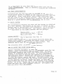
-
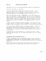
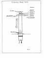
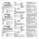
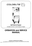
Gravity Feed Valve How to
Operate and Make Adjustments
Gravity Feed ~ u b &
Adjustment Settings
.
The Gravity Feed Valve consists of two tubes, one sliding inside
the other, and a plunger/splash guard.
'
The inner tube blends the flow of air and mix into the freezing
cylinder. Air enters through the top of the tube and the mix,
through a round hole at the base. See illustration below.
The plunger/splash guard keeps the mix from splashing on the
mix tank cover and serves as a device to eliminate potential
clogging inside the tubes.
,You may find it necessary to adjust the position of the outer
tube in order to regulate the amount of mix entering the
freezing cylinder after start-up. Actually, sales conditions will
dictate the proper adjustment.
If more production is required, increase the opening by rotating
the outer tube to a larger hole, and conversely when business
is slow, rotate to a smaller hole on the outer tube, reducing the
opening. Naturally, when the mix runs low in the mix tank, you
will open the slot more and eventually take the feed tube out
completely to use the last of mix in the mix tank.
Energy Conservation
During long idle periods, it is recommended the, outer sleeve of
the gravity feed tube be rotated to the position which closes
the mix intake hole completely.
.
The outer tube is actually a valve. Rotating it from hole to fiole
on the outer tube varies the size of the hole and the amount of
mix that flows into the freezing cylinder. The size of the air
inlet, at the top of the tube, does not change so the amount of
air that enters the freezing cylinder is constant.
You can vary the overrun (yield) by letting more or less mix
enter the freezing cylinder by manually regulating the valve.
You must align the mix inlet holes on both the inner and outer
tubes or no mix will enter the cylinder. You can see this hole at
the top of both tubes. See illustration below.
IMPORTANT: Remember to rotate the outer tube to the appropriate opening before switching to the AUTO mode.
M A I N T E N A N C E
Your COLDELITE machine h a s b e e n d e s i g n e d , e n g i n e e r e d and manuf a c t u r e d t o a c h i e v e h i g h p e r f o r m a n c e and l o n g d u r a b i l i t y .
The l i f e e x p e c t a n c y o f a m a c h i n e , any machine, d o e s n o t depend
o n l y on t h e q u a l i t y o f i t s components and d e s i g n , b u t a l s o o n
t h e b e n e f i c i a l e f f e c t s of b a s i c m a i n t e n a n c e p r o c e d u r e s .
I t i s i m p o r t a n t t o you, t h e r e f o r e , t o become f a m i l i a r w i t h a
few o f t h e s e b a s i c p r o c e d u r e s :
Remove ' 0 ' r i n g s o n l y w i t h t h e ' 0 ' r i n g e x t r a c t o r s u p p l i e d
w i t h t h e machine.
C l e a n t h e machine a c c o r d i n g t o t h e i n s t r u c t i o n s .
L u b r i c a t e a l l ' 0 ' r i n g s and s e a l s , a s i n s t r u c t e d .
The w e a r i n g o r t h e i m p r o p e r c l e a n i n g of t h e b e a t e r and t h e
pump s h a f t s e a l s , w i l l r e s u l t i n l e a k a g e from t h e r e a r .
C h e c k s t h e d r i p c h u t e p a n s f r e q u e n t l y and r e p l a c e s e a l s , when
necessary.
Replace any ' 0 ' r i n g t h a t h a s a nick i n it. I t w i l l l e a k
a n d i n t e r f e r e w i t h t h e p r o p e r performance o f t h e machine.
When a l l t h e s p a r e p a r t s s u p p l i e d w i t h t h e machine a r e u s e d ,
r e - o r d e r immediately.
Do n o t w a i t u n t i l t h e p a r t i s r e q u i r e d
again.
NEVER u s e t h e AUTO p o s i t i o n p o s i t i o n f o r w a s h i n g , s a n i t i z i n g ,
and i n i t i a l l y f i l l i n g t h e f r e e z i n g c y l i n d e r .
IMPORTANT - During t h e w a s h i n g and s a n i t i z i n g p e r i o d , r u n t h e
machine o n l y f o r t h e t i m e s t r i c t l y necessary f o r t h i s operation.
P r o l o n g e d u s e of t h e beater i n t h e c l e a n i n g p o s i t i o n
may c a u s e s e v e r e damage t o t h e machine.
Always wash m e t a l , p l a s t i c o r r u b b e r p a r t s i n lukewarm w a t e r .
NEVER, NEVER USE HOT WATER!
You s h o u l d b e a b l e t o
Check t h e b e l t t e n s i o n p e r i o d i c a l l y .
d e p r e s s t h e b e l t a b o u t 3 / 8 o f a n i n c h between t h e p u l l e y
and t h e f l y w h e e l .
Page 1 6
I M P O R T A N T
THE MODEL UC-71G I S AN A I R COOLED MACHINE AND THUS
I T S E F F I C I E N C Y DEPENDS ON THE A I R COOLED CONDENSER.
THE F I N S O F THE CONDENSER MUST BE CLEANED EVERY TWO
OR T H R E E MONTHS TO ASSURE E F F I C I E N C Y .
W A R N I N G
EXTREME CARE MUST BE TAKEN WHEN REMOVING S I D E ,
OR CONTROL BOX PANELS.
REAR
OFF POSITION.
ALWAYS TURN T H E SELECTOR SWITCH TO THE A L S O , TURN O F F DISCONNECT SWITCH ON ELECTRICAL SUPPLY
L I N E BEFORE EXPOSING ANY E L E C T R I C A L CONNECTIONS AND/OR
MOVING P A R T S , SUCH A S B E L T S , P U L L E Y S , FAN BLADES AND
BEATER.
Page 17
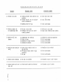
T R O U B L E
S H O O T I N G
G U I D E
SUGGESTED REMEDY
PROBABLE CAUSE
PROBLEM
1) Product too soft
A) Drawing faster than machine can
produce.
B) Torque control out of calibration or defective
C) Machine short of gas
A) Slow down draw rate
A) No mix in mix tank
B) Feeding tube hole not sufficiently opened.
A) Add mix to mix tank
B) Open outer feeding tube jacket.
A) Compressor not working
B ) Short of gas
C) Defective torque control
D) Defective starter
A)
B)
C)
D)
A) Front micro switch stuck on
ON position
B) 10 Minute Timer stuck on ON
position
C) No gas
A) Readjust micro switch
5) Beater motor humming
A) No mix in cylinder
A) Proceed as per 1 and 4 above
6) Beater motor will not
A) Front micro switch activated
A) Proceed as per 4 above
2) Nothing comes out
of dispensing head
3) Machine will not
freeze
-
4) Machine runs continuously
.,
shut off
:9
B) Call serviceman
C) Call serviceman
Defective starting capacitor
Call serviceman
Call serviceman
Call serviceman
B) Call serviceman
C) Call serviceman
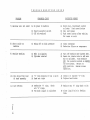
T R O U B L E
PROBLEM
S H O O T I N G
G U I D E
PROBABLE CAUSE
SUGGESTED REMEDY
B) Faulty selector switch
C ) Off on overload
A) Check plug, disconnect switch
or fuses. Push reset button
B) Call serviceman
C ) Push reset button after waiting
for reset to cool.
8) Short cycle on
machine
A) Going off on high pressure
A) Clean condenser
B) Defective Klixon on compressor
9) Machine smoking
A) Belt is slipping
B) Cylinder starved
A) Turn off machine and tighten belt.
B) Reset mix intake tube to add more
mix to cylinder. Turn machine
OFF. Put selector switch on BEATER
for one minute. Return to
AUTO position. Resume nor~i~al
operation.
7) Machine will not start
A) No power to machine
. -. .-
10) Mix drips from rear
of head assembly
11) Low overrun
,
A) '0' ring missing or has a split
B) Head not tight
A) Install or replace '0' ring
B) Tighten hand knobs
A) Defective '0' ring. Check
all '0' rings.
B ) Too much liquid in cylinders
A) Replace any ' 0 ' ring with a nick
B) Close liquid hole in feeding
tube.
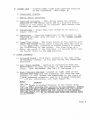
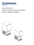
Model
UC-71 C
Fig. 1
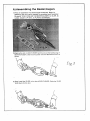
Beater, Drive Assembly
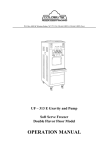
A) Assembling the BeateVAugers
1) First, re-assemble the beaterlauger assembly. Begin by
gathering t h e four parts needed to complete each assembly:
A) plastic "END PUSHER", B) BEATERIAUGER, C) IDLER, D)
rubber, beater LIP SEAL, E) PLASTIC SCRAPERS
2)Aligning the slot on END PUSHER and the one on the holding ring of
BEATEWAUGER, slide the end pusher onto the BEATERIAUGER as
shown.
......
. ..
fig 3
3) Next, install the IDLER, in the slot of END PUSHER. Guide the IDLER
shaft down into the slot.
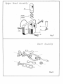
F ~ o n Micro
t
Switch Assembly
M i x Tank C o v e r
Fig. 5
h.
Gravity Feed Tube
Production
Maximum
Air Intake
Moderate H.
1
I
Moderate L.
-
1I
.
-
~ n e & Conservation
Mix Intake
-a
d
l
Fig. 6
S p igo t H e a d A s s e m b l y
Fig. 7
B e a f e r Assembly
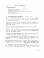
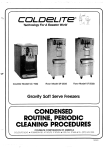
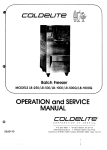
SELECTOR SWITCH
TRANSFORMER
TERMINAL BLOCK
THERMOSTAT
OVERLOAD PROTECTOR
BEATER MOTOR CONTACTOR
COMPRESSOR CONTACTOR
REAR MICRO SWITCH
TERMINAL BLOCK
TIMER
'
FILTER/DRYER
TENSION S P R I N G
CONDENSER F A N
BEATER MOTOR
HIGH
g*9
PRESSURE CUT-OUT
HIGH S I D E ACCESS
COMPRESSOR R E L A Y
M o d e l UC-71G R i g h t Side View
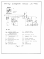
'IIZ7iring D i a g r a m
M o d e l UC-71 G
AB AC AD A €
ENERGY CONSERVATION
AUTOMATIC
CR=BR
39003
FU - Fuse
PR
-
CAC
MC
-
Compressor Motor
- Starting
MIA
-
Rear Micro Switch
PT
-
O v e r l o a d Protector
MIR
7
Spigot Micro Switch
RTA
-
O v e r l o a d Protector f o r
Beater Motor
RA
- :Compressor
Rotary Switch
TEC
- storage
TTA
-
B e a t e r Motor C o n t a c t o r
Beater Motor
TTC
-
Compressor Motor C o n t a c t o r
Transformer
TZF
-
Timer
CR
Pressure Control
C a p a c i t o r for
Compressor Motor
-
EVC - C y l i n d e r S o l e n o i d Valve
MA
TR
-
IML - Level magnetic switch
Motor S t a r t i n g
Relays
Thermostat
LSL - Level pilot lamp
figure 1 0