1
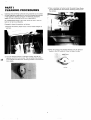
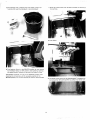
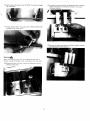
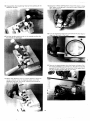
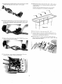
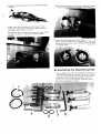
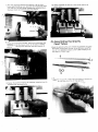
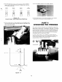
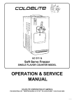
Technology For A Sweeter World
Counter Model UC-113G
Floor Model UF-203G
Floor Model UF-253G
Gravity Soft Serve Freezers
CONDENSED
ROUTINE, PERIODIC
CLEANING PROCEDURES
COLDELITE CORPORATION OF AMERICA
COLDELITE BLDG.
ROBINSON RD. AT ROUTE 17 SOUTH
LODI, N.J. 07644
TEL. (201)843-7400
PART I
CLEANING PROCEDURES
3) Place a container or bucket under the spigot head. Slowly
pull the handle down and remove remaining product from
the cylinder.
Cleaning and sanitizing schedules are governed by your State
or local regulatory agencies and must be followed accordingly.
A well planned cleaning schedule will eliminate excessive
waste of time and product within your organization.
On a designated day(s) of the week, allow the mix in the mix
tank t o run as low as feasible.
Proceed t o clean the machine, as follows:
1) Remove the Gravity Feed Tubes. Pull the tubes straight up
and out.
4) When the product has stopped flowing, turn the Selector
Switch to the OFF position. Close the spigot handle.
2) Turn the Selector Switch to BEATER position and let the
machine run for 4 t o 5 minutes. This will soften the product
in the cylinder and allow the remaining product to be removed
more easily.
5 ) Fill hopper@)and cylinder(s) with cold water (a mild, nonfoaming dish washing detergent is recommended).
7) Brush all surface areas, with brushes provided, to remove all
mix particles.
8) Drain Water:
6) Turn Selector Switch to the BEATER position for one minute.
Turn Selector Switch to OFF position, drain water by opening
the spigot handle. Repeat this process until water is clear.
IMPORTANT: Operate unit only in the BEATER position when
cleaning. Do not operate unit for excessive periods in the
BEATER position, one minute intervals per rinse is recommended.
9) The Gravity Tubes must now be disassembled. To disassemble,
first remove the "SPLASH GUARD" by pulling it out of the tube.
10) Next, remove the gravity tube "SLEEVE" by pulling it straight
off of the tube.
13) Loosen and remove the four (4) dispensing head retaining
knobs. The knobs are removed by turning in a counterclockwise direction.
11) Finally, remove the o-rings using the O-RING EXTRACTOR
included in the "start-up kit".
14) Remove the dispensing head by pulling it straight towards
you and away from the machine.
warnings
Never use anything other than the O-RING EXTRACTOR to
remove o-rings as damage to the o-ring and/or part can result
12) Remove the two mix level "floats" by lifting them off the
stainless steel shaft.
15) Disassemble the dispensing head by first opening all the
dispense handles.
18) Using the O-RING EXTRACTOR, remove the piston o-rings
Each piston O-ring groove is notched for easy insertion of
the o-rina extractor.
19) Turn the dispensing head over and remove the two large 0 rinas from the back of the head.
16) Pull the handle retaining rod out far enough to allow the
first handle to disengage.
20) Remove the beater/augers from the freezer cylinders. Pull
the beaters STRAIGHT out towards you. Should they become
jammed, DO NOT FORCE. Tap the,front of the beater back
into the cylinder with the palm of your hand.
17) Return the retaining rod to its orig~nalposition. Using the
rod as a fulcrum, lever the dispense piston out of the
dispense head with the handle. Repeat this process for
each of the three pistons.
21) Disassemble the beater/auger by first removing the rubber
beater shaft (lip) seal, simply slide it off the shaft.
25) Wash all the parts in luke warm water (80" - 85'F) using a
mild detergent and the cleaning brushes provided in the
START-UP KIT.
DO NOT USE HOT WATER O N ANY OF THE PLASTIC
PARTS AS DAMAGE TO THE PARTS CAN RESULT.
41 Alr Dry
3' San'tlze
22) Continue disassembly by removing the beater IDLER. Pull
forward until the grooved portion of the shaft lines up with
the opening at the front of the beater/auger. Lift the idler
up and out.
n
\
t
Figure 10
26) Rinse the parts in luke warm water (80 - 85 F)
27) Place the parts in luke warm, sanitized water for 2 to 5
minutes. Use the sanitizer provided In the START-UP KIT
following the manufacturers directions.
23) Finally, remove the beaterlauger END PUSHER by pulling
straight and away from the beater.
24) The machine is now completely disassembled. The parts
should now be washed, rinsed and sanitized.
28) Place the parts on a clean, sanitized counter area and
allow to air dry or assemble wet. DO NOT TOWEL DRY OR
RINSE SANITIZED PARTS.
PART I1
ASSEMBLING
THE FREEZER
Push the idler back, inserting its shaft into the hole of the
beaterlauaer shaft.
Once the parts have been washed, rinsed and sanitized, the
freezer is ready to be re-assembled. Prior to beginning the reassembly procedure, sanitize your hands by submerging in the
sanitizing solution. Begin to re-assemble as follows:
A) Assembling the Beater/Augers
1) First, re-assemble the beater/auger assembly. Begin by
gathering the four parts needed to complete each assembly:
A) plastic "END PUSHER", B) BEATERIAUGER, C) IDLER, D)
rubber, beater LIP SEAL.
When installed correctly, the idler (when turned) should rotate
freely. If the idler does not rotate, it is incorrectly installed
and must not be installed into the machine. Repeat the
above instructions.
4) Next, lubricate and install the beater lip seal by first lubricating
the beaterlauger shaft with the lubricant included in the
START-UP KIT. Place three, 114" beads in equal distances
around the shaft as shown below.
Sl~dethe rubber, beater Ilp seal onto the shaft.
2) Al~qninsthe end-pusher slot w ~ t hthe slotted shaft located at
the-froit
of the beater/auger, slide the end pusher onto the
3 ) Next, install the idler. Holding the idler in a horizontal
position, turn the idler until the fins are in an upright position.
Then insert the idler by aligning the thinner portion of the
Lubricate the end of the beater lip seal which is not lubricated
by placing three, 114" beads in equal distances around the
seal surface as shown below.
5) Repeat the above procedure for the second beaterlauger
assembly.
Rotate the beater/auger until you feel the drive shaft engage
6) Finally, insert the beaterlauger into the freezer cylinder.
Halding the beaterlauger horizontally, slide it straight into
the cylinder until it can go no further.
IMPORTANT: Before installing the beaterlauger, make certain
the beater lip seal is in place and the idler is properly
7) Insert the second beaterlauger. Once installed, make certain
the flat portion of the idler is in a vertical position. The idlers
should spin freely and are counter weighted to naturally rest
in a vertical position.
B) Assembling the Dispensing Head
1) Begin by gathering all the parts necessary to assemble the
dispensing head. These parts include: A) two (2),4" diameter
O-rings, B) the dispending head<body,C) the center piston
O-ring, D) four (4), 13/d' diameter end piston O-rings, E)
center piston, F) two (2) end pistons, G) handle retaining
rod. H) three (3) dispense handles.
2) First, remount the end piston O-rings onto the end pistons.
Simply roll onto the piston until they drop into the O-ring
notches.
5) Insert the two end pistons into the two end chambers of
the dispensing head body making certain to align the
square notch of the piston with the rectangular notch at
the front of the dispense head. Repeat this process with
center piston and center chamber.
3) Remount the center piston O-ring onto the center piston.
This O-ring and piston are easily identified as they appear
to b e two O-rings and O-ring grooves interconnected by
two vertical posts.
6) Turn the dispense head over and install the two 4" diameter
O-rings into O-ring grooves located in the back of the
head.
4) Once the O-rings have been mounted, liberally lubricate
the area between the two O-rings. Place a bead of lubricant
around the entire piston as shown.
Lightly lubricate the O-rings with the sanitary lubricant.
Spread the lubricant on the surface area between the two
O-rings and the O-rings as well. This will ensure free
movement of the dispense handles once the head is
completely assembled.
7) Affix the dispensing head t o the machine. Lift the front
micro switch activating lever and slide the dispensing head
onto the four mounting studs. Release the activating lever,
the lever should rest vertically atop the pistons.
8) Install the dispensing handles. Insert the round lobe of the
handle cam into the square notch of the piston. Slide the
retaining rod through the dispense head and cam hole to
secure.
10) HAND TIGHTEN the knobs in a criss-cross manner as
shown below.
C) Assembling the Gravity
Feed Tubes
1) Begin by gathering the parts needed to assemble the gravity
feed tubes. These parts include: A) the SPLASH GUARD, B)
two (2) 314" diameter O-rings, C) the TUBE SLEEVE, and D)
the GRAVITY FEED TUBE.
2) Slide the two (2) 314" O-rings onto the bottom of the gravity
feed tube until they drop in the O-rings grooves.
9) Fasten the dispense head t o the machine using the four (4)
stainless steel retaining knobs.
3) Slide the sleeve onto the tube. Please note that the slots in
the sleeve should be at the top of the tube when installed.
7) Install the two (2) mix level floats by simply sliding one each
onto the stainless steel shaft in the mix tank.
4) Slide the splash guard into the tube.
The machine is now completely assembled and ready to be
sanitized.
PART Ill
SANITIZING THE FREEZER
5) Lubricate the two O-rings with sanitary lubricant.
Prior to starting the machine with your soft serve product, the
machine must be sanitized. The frequency of cleanina and
- .sanitizing cycles must comply with local health regulations. If
uncertain about local regulations, contact your local Board of
Health.
-
Sanitizing the machine is most important. This procedure will
retard the growth of bacteria and insure excellent test results
on your product when examined by local Health and/or
Agriculture Departments.
6) Insert the assembled tubes into the hole at the bottom of
the mix tank. Press the tube down until it seats and the
flange at the base of the tube rests against the bottom of
the mix tank.
To begin, you will need a clean pail, sanitizer (sample packets
included in the start-up kit), spatula (included in start-up kit),
and brush (plastic bristle).
%$
1) Mix the san~tlzer(2 ounces of Steera Sheen green label or
equ~valent)Into a clean pall c o n t a ~ n ~ ntwo
g gallons of warm
water. T h ~ ssolut~onwill make a 200 P.P.M (parts per rnllllon)
concentration of chlorlne sanitmng solut~onPour the ~ o l u t l 0 n
into t h e mlx tanks.
4) Turn the selector swltch to the "OFF" pos~t~on.
ENERGYCONS
5) Using a sanitized soft bristle brush, brush the sides of the
mix tank, and all other product contact areas. Allow the
sanitizing solution to remain in contact with all product
contact areas for three to five minutes.
IMPORTANT: Do not exceed the formula recommended b y the
sanitizer manufacturer as i t will not add to its effectiveness.
2) Pull the gravity feed tubes out of the mix tank holes and lay
them down in the tank. This will allow the cylinders to
c o m ~ l e t e l yfill with the sanitizing solution.
6) Place the clean, sanitized pail under the dispensing head
and open the handles by pulling them in a downward direction.
3) Turn the selector switch to the "BEATER" position for 30
seconds.
7) Allow the sanitizer to completely drain. Close handles.
2) Rest the gravity feed tubes upright against the side of mix
tank as shown.
3) Pour ll/z pints of mix into each mix tank. Allow the mix to
drain into the freezer cylinders. This will properly "prime"
each cylinder.
HELPFUL SUGGESTION: When the sanitizer stops flowing,
leave the handles open and turn the selector switch to the
"BEATER" position for two to three seconds to help remove the
last of the sanitizer.
CAUTION: We recommend the beater/auger be turned as little
as possible during the washing and sanitizing operations.
Excessive use will cause premature wear to the beater/auger
and cylinders.
PART IV
STARTING THE FREEZER
Only after the machine has been thoroughly cleaned and
sanitized is the unit ready for production.
Start the machine as follows:
1) Pour 1 % pints of liquid mix (soft serve ice cream, ice milk,
frozen yogurt, dietary or non-dairy mix) into a clean, sanitized
measuring container.
SUGGESTION: When initially pouring mix into the tank, it is
recommended the dispense handles be opened to allow any
residual sanitizer to be "chased" out by the mix entering the
cylinders. Place a cup under the dispense head to catch any
residual sanitizer, 2 - 3 oz. is sufficient to purge the sanitizer
out.
4) Once the pre-measured 1% pints of mix has completely
drained into the freezing cylinders, insert the gravity feed
tubes into the holes at the bottom of the mix tank. Make
certain the hole at the top of sleeve and tube are facing
toward the front of the machine and are visible.
5 ) Turn the adjustment sleeve of the aravity until the medium
sized hole for moderate production-is aligned with the hole
in the gravity feed tube.
A+i:
Mlnlmum
Production
Moderaie
Productton
Maxlmum
Production
7 )Turn the selector switch to the "AUTO" position.
Energy
conservation
Figure 12
Gravity Feed Tube Adjustment Settings
6) Fill the tanks w ~ t hmix. Total capacity is two (2) gallons each.
Never fill the tanks higher than the bottom of the slots in the
gravity feed tube sleeve.
8) Initial freeze-down of the product will take 7 - 1 0 minutes
dependent on the type of product being frozen.
PART V
OPERATING THE FREEZER
The machine will automatically shut-off when the product has
been frozen to the pre-set "consistency". After the 7-10 minute
initial freeze-down period, you will hear the beaterlauger drive
motor shut down indicating the product is ready t o be served.
The compressor will continue to run for a short period as the
machine automatically directs refrigeration to the mix tanks
immediately after the freeze-down cycle.
To serve, simply place a cup, container or cone under the
dispensing spout and slowly pull the dispensing handle down.
As the product begins to flow, move the cup or cone in a
circular fashion to create a tapering tower.
Max FIII Level
-
Figure d 1
When the portion is the size you want, close the handle and
pull the cup or cone straight down to add a peak.
The outer tube is actually a valve. Rotating it from hole to hole
on the outer tube varies the size of the hole and the amount of
mix that flows into the freezing cylinder. The size of the alr
inlet, at the top of the tube, does not change so the amount of
air that enters the freezing cylinder is constant.
You can vary the overrun (yield) by letting more or less mix
enter the freezing cyl~nderby manually regulating the valve.
You must align the mix inlet holes on both the inner and outer
tubes or no mix will enter the cylinder. You can see this hole at
the top of both tubes. See illustration below.
Figure 1 2
Gravity Feed Tube Adjustment Settings
Typical portion sizes are: SMALL = 3 OUNCE SERVING
MEDIUM = 5 OUNCE SERVING
LARGE = 7 OUNCE SERVING
Gravity Feed Valve - HOWto
Operate and Make Adjustments
The Gravity Feed Valve consists of two tubes. one slid~rlginside
the other, and a plungerlsplash guard.
The inner tube blends the flow of air and mix into the freezing
cylinder. Air enters through the top of the tube and the mlx.
through a round hole at the base. See illustration below
The plunger/splash guard keeps the mix from splashing on the
mix tank cover and serves as a device to eliminate potent~al
clogging inside the tubes
You may find it necessary to.adjust the position of the outer
tube in order to regulate the amount of mix entering the
freezing cylinder after start-up. Actually, sales conditions will
dictate the proper adjustment.
If more production is required, increase the opening by rotating
the outer tube to a laraer
- hole, and converselv when business
is slow, rotate to a smaller hole on the outer tube, reducing the
opening. Naturally, when the mix runs low in the mix tank, you
will open the slot more and eventually take the feed tube out
completely to use the last of mix in the mix tank.
Energy Conservation
During long idle periods. it is recammended the outer sleeve of
the gravity feed tube be rotated to the position which closes
the mix intake hole completely.
IMPORTANT. Remember to rotate the outer tube to the appropriate opening Sefore switching to the AUTO mode.
For further Operational or Technical Data, please refer to the
"Operation and Service Manual" or contact your authorized
Coldelite Distributor or Service Agency.
All technical data, pictures and drawings contained in this
leaflet are not binding on the manufacturer; nor can the
manufacturer be held liable for any modification of the machine
in part or completely.
dL
Figure 11
.,