1
Order No. PHAAM1010087C2
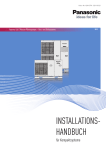
Monobloc Air-to-Water Heatpump System
Monobloc Unit
WH-MDF09C3E8
WH-MDF12C9E8
WH-MDF14C9E8
WH-MDF16C9E8
WARNING
This service information is designed for experienced repair technicians only and is not designed for use by the general public.
It does not contain warnings or cautions to advise non-technical individuals of potential dangers in attempting to service a product.
Products powered by electricity should be serviced or repaired only by experienced professional technicians. Any attempt to
service or repair the product or products dealt with in this service information by anyone else could result in serious injury or death.
PRECAUTION OF LOW TEMPERATURE
In order to avoid frostbite, be assured of no refrigerant leakage during the installation or repairing of refrigerant circuit.
© Panasonic HA Air-Conditioning (M) Sdn. Bhd. 2010.
Unauthorized copying and distribution is a violation of law.
TABLE OF CONTENTS
PAGE
PAGE
1
Safety Precautions .............................................3
12.15. External Room Thermostat Control
(Optional)................................................... 61
2
Specifications .....................................................5
2.1.
2.2.
2.3.
2.4.
13 Protection Control ........................................... 62
WH-MDF09C3E5 ...........................................5
WH-MDF12C6E5 ...........................................7
WH-MDF14C6E5 ...........................................9
WH-MDF016C6E5 .......................................11
3
Features.............................................................13
4
Location of Controls and Components..........14
13.1. Protection Control for All Operations .......... 62
13.2. Protection Control for Heating Operation.... 63
14 Servicing Mode ................................................ 64
14.1.
14.2.
14.3.
14.4.
4.1. Monobloc Unit ..............................................14
5
Dimensions .......................................................21
15 Maintenance Guide.......................................... 65
5.1. Monobloc Unit ..............................................21
6
Refrigeration And Water Cycle Diagram........22
7
Block Diagram ..................................................24
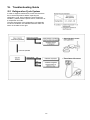
16 Troubleshooting Guide................................... 67
16.1. Refrigeration Cycle System ........................ 67
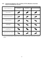
16.2. Relationship between the Condition of
the Air-to-Water Heatpump Indoor and
Outdoor Units and Pressure and Electric
Current ........................................................ 68
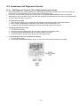
16.3. Breakdown Self Diagnosis Function ........... 69
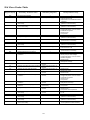
16.4. Error Codes Table....................................... 70
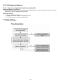
16.5. Self-diagnosis Method ................................ 72
7.1. WH-MDF09C3E8 .........................................24
7.2. WH-MDF09C9E8 WH-MDF12C9E8
WH-MDF14C9E8 .........................................25
8
Wiring Connection Diagram ............................26
8.1. WH-MDF09C3E8 .........................................26
8.2. WH-MDF12C9E8 WH-MDF14C9E8
WH-MDF16C9E8 .........................................28
9
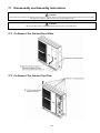
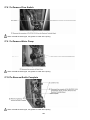
17 Disassembly and Assembly Instructions ... 105
17.1.
17.2.
17.3.
17.4.
17.5.
17.6.
To Remove The Cabinet Front Plate ........ 105
To Remove The Cabinet Top Plate .......... 105
To Remove The Cabinet Rear Plate......... 106
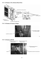
To Remove Pressure Gauge .................... 106
To Remove RCCB .................................... 106
To Remove Transformer and Electronic
Controller Board........................................ 107
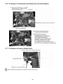
17.7. To Remove Pressure Relief Valve............ 107
17.8. To Remove Flow Switch ........................... 108
17.9. To Remove Water Pump .......................... 108
17.10. To Remove Bottle Complete ................. 108
Electronic Circuit Diagram ..............................30
9.1. WH-MDF09C3E8 .........................................30
9.2. WH-MDF12C9E8 WH-MDF14C9E8
WH-MDF16C9E8 .........................................32
10 Printed Circuit Board .......................................34
10.1. Water System ..............................................34
10.2. Refrigerant System ......................................36
11 Installation Instruction.....................................38
11.1.
11.2.
11.3.
11.4.
Test Run ..................................................... 64
Proper Pump Down Procedure................... 64
How to Adjust Water Flow Rate.................. 64
Expansion Vessel Pre Pressure
Checking ..................................................... 64
Select the Best Location ..............................40
Monobloc Unit Installation............................40
Piping Installation.........................................41
Connect The Cord And Cable To Monobloc
Unit...............................................................42
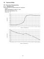
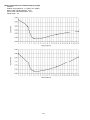
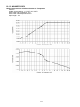
18 Technical Data ............................................... 109
12 Operation and Control .....................................47
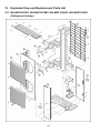
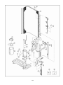
19 Exploded View and Replacement Parts
List ............................................................... 118
18.1. Operation Characteristics ......................... 109
18.2. Heating Capacity Table............................. 117
18.3. Hydraulic Pump Performance................... 117
12.1. Basic Function .............................................47
12.2. Water Pump .................................................54
12.3. Pump Down Operation ................................54
12.4. Flow Switch..................................................54
12.5. Force Heater Mode Operation .....................55
12.6. Monobloc Unit Safety...................................55
12.7. Auto Restart Control ....................................55
12.8. Indication Panel ...........................................56
12.9. Back-Up Heater Control...............................56
12.10. Tank Booster Heater Control......................57
12.11. Three Way Valve Control ...........................57
12.12. Sterillization Mode ......................................57
12.13. Quiet Operation ..........................................57
12.14. Solar Operation (Optional) .........................58
19.1. WH-MDF09C3E5 WH-MDF12C6E5
WH-MDF14C6E5 WH-MDF16C6E5......... 118
19.2. WH-MDF09C3E5 WH-MDF12C6E5
WH-MDF14C6E5 WH-MDF16C6E5......... 123
2
1. Safety Precautions
Read the following “SAFETY PRECAUTIONS” carefully before perform any servicing.
Electrical work and water installation work must be installed or serviced by a licensed electrician and licensed
water system installer respectively. Be sure to use the correct rating and main circuit for the model installed.
The caution items stated here must be followed because these important contents are related to safety. The
meaning of each indication used is as below. Incorrect installation or servicing due to ignoring of the instruction
will cause harm or damage, and the seriousness is classified by the following indications.
WARNING
This indication shows the possibility of causing death or serious injury.
CAUTION
This indication shows the possibility of causing injury or damage to properties.
The items to be followed are classified by the symbols:
This symbol denotes item that is PROHIBITED from doing.
Carry out test run to confirm that no abnormality occurs after the servicing. Then, explain to user the operation,
care and maintenance as stated in instructions. Please remind the customer to keep the operating instructions for
future reference.
WARNING
1. Do not modify the machine, part, material during repairing service.
2. If wiring unit is supplied as repairing part, do not repair or connect the wire even only partial wire break. Exchange the whole wiring unit.
3. Do not wrench the fasten terminal. Pull it out or insert it straightly.
4. Engage dealer or specialist for installation and servicing. If installation of servicing done by the user is defective, it will cause water leakage,
electrical shock or fire.
5. Install according to this installation instructions strictly. If installation is defective, it will cause water leakage, electric shock or fire.
6. Use the attached accessories parts and specified parts for installation and servicing. Otherwise, it will cause the set to fall, water leakage,
refrigerant leakage, fire or electrical shock.
7. Install at a strong and firm location which is able to withstand the set’s weight. If the strength is not enough or installation is not properly done,
the set will drop and cause injury.
8. Do not install outdoor unit near handrail of veranda. When installing outdoor unit at veranda of high rise building, child may climb up to
outdoor unit and cross over the handrail and causing accident.
9. For electrical work, follow the local national wiring standard, regulation and the installation instruction. An independent circuit and single outlet
must be used. If electrical circuit capacity is not enough or defect found in electrical work, it will cause electrical shock or fire.
10. This equipment must be properly earthed. Earth line must not be connected to gas pipe, water pipe, earth of lightning rod and telephone.
Otherwise, it may cause electric shock in case equipment breakdown or insulation breakdown.
11. Do not use joint cable for monobloc unit connection cable. Use specified monobloc unit connection cable, refer to Installation
Instructions CONNECT THE CABLE TO THE MONOBLOC UNIT and connect tightly for monobloc unit connection. Clamp the cable
so that no external force will be acted on the terminal. If connection or fixing is not perfect, it will cause heat up or fire at the connection.
12. When install or relocate monobloc unit, do not let any substance other than the specified refrigerant, eg. air etc. mix into refrigerant
cycle (piping). Mixing of air etc. will cause abnormal high pressure in refrigeration cycle and result in explosion, injury etc.
13. This is a R410A model. When connecting the piping, do not use any existing (R22) pipes and flare nuts. Using such same may cause
abnormally high pressure in the refrigeration cycle (piping), and possibly result in explosion and injury. Use only R410A refrigerant.
Thickness of copper pipes used with R410A must be more than 0.8 mm. Never use copper pipes thinner than 0.8 mm. It is desirable
that the amount of residual oil is less than 40 mg/10 m.
14. During installation, install the refrigerant piping properly before run the compressor. Operation of compressor without fixing refrigeration piping
and valves at opened condition will cause suck-in of air, abnormal high pressure in refrigeration cycle and result in explosion, injury etc.
15. During pump down operation, stop the compressor before remove the refrigeration piping. Removal of refrigeration piping while compressor is
operating and valves are opened condition will cause suck-in of air, abnormal high pressure in refrigeration cycle and result in explosion, injury
etc.
16. After completion of the installation servicing confirm there is no leakage of refrigerant gas. It may generate toxic gas when the refrigerant
contacts with fire.
17. Ventilate the room if there is refrigerant gas leakage during operation. Extinguish all fire sources if present. It may cause toxic gas when the
refrigerant contacts with fire.
18. Only use the supplied or specified installation parts, else, it may cause unit vibrate loose, water/refrigerant leakage, electrical shock or fire.
3
WARNING
19. The unit is only for use in a closed portable water system. Utilization in an open water circuit or non-portable water circuit, may lead to
excessive corrosion of the water piping and risk of incubating bacteria colonies, particularly Legionella, in water.
20. Do not insert your fingers or other objects into the unit, high speed rotating fan may cause injury.
21. Do not dismantle refrigerant piping using pipe wrench. It might deform the piping and cause the unit to malfunction.
22. Select a location where in case of water leakage, the leakage will not cause damage to other properties.
23. Do not locally purchase electrical parts of the product for the purpose of installation, service, maintenance and etc. They might cause
electrical shock or fire.
24. Do not branch the power from terminal block to heater tape. Overloaded terminal block will cause electrical shock or fire.
25. Installation or servicing work. It may need four or more people to carry out the installation or servicing work.
26. Do not use unspecified cord, modified cord, joint cord or extension cord for power supply cord. Do not share the single outlet with other
electrical appliances. Poor contact, poor insulation or over current will cause electrical shock or fire.
27. Tighten the flare nut with torque wrench according to specified method. If the flare nut is over-tightened, after a long period, the flare may
break and cause refrigerant gas leakage.
CAUTION
1. Do not install the monobloc unit at place where leakage of flammable gas may occur. In case gas leaks and accumulates at
surrounding of the monobloc unit, it may cause fire.
2. Carry out drainage piping as mentioned in installation instructions. If drainage is not perfect, water may enter the room and damage
the furniture.
3. It may need four or more persons to carry out the installation work. The weight of monobloc unit might cause injury if carried by less than four
person.
4. Do not touch monobloc unit air inlet and aluminum fin. It may cause injury.
5. Select an installation location which is easy for maintenance.
6. Pb free solder has a higher melting point than standard solder; typically the melting point is 50°F - 70°F (30°C - 40°C) higher. Please
use a high temperature solder iron. In case of the soldering iron with temperature control, please set it to 700 ± 20°F (370 ± 10°C).
Pb free solder will tend to splash when heated too high (about 1100°F / 600°C).
7. Power supply connection to Monobloc unit.
Power supply point should be in easily accessible place for power disconnection in case of emergency.
Must follow local national wiring standard, regulation and this installation instruction.
Strongly recommended to make permanent connection to a circuit breaker.
For WH-MDF09C3E8:
- Power 1: Use approved 20A 4-poles circuit breaker with a minimum contact gap of 3.0mm.
- Power 2: Use approved 15/16A 2-poles circuit breaker with a minimum contact gap of 3.0mm.
For WH-MDF12C9E8,WH-MDF14C9E8,WH-MDF16C9E8:
- Power 1: Use approved 20A 4-poles circuit breaker with a minimum contact gap of 3.0mm.
- Power 2: Use approved 15/16A 2-poles circuit breaker with a minimum contact gap of 3.0mm.
- Power 3: Use approved 15/16A 4-poles circuit breaker with a minimum contact gap of 3.0mm.
8. Do not release refrigerant during piping work for installation, servicing, re-installation and during repairing a refrigeration parts. Take
care of the liquid refrigerant, it may cause frostbite.
9. Do not install this appliance in a laundry room or other high humidity location. This condition will cause rust and damage to the unit.
10. Make sure the insulation of power supply cord does not contact to hot part (i.e. refrigerant piping, water piping) to prevent from
insulation failure (melt).
11. Do not sit, step or place anything on the unit, you may fall down accidentally.
12. Do not touch the sharp aluminum fins or edges of metal parts.
If you are required to handle sharp parts during installation or servicing, please wear hand glove.
Sharp parts may cause injury.
13. After installation, check the water leakage condition in connection area during test run. If leakage occur, it will cause damage to other
properties.
14. The unit described in this manual is designed for use in a closed water system only. Utilization in an open water circuit may lead to
excessive corrosion of the water piping.
4
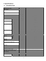
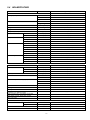
2. Specifications
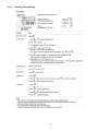
2.1
WH-MDF09C3E8
Item
Performance Test Condition
Unit
Refrigerant System
Heating Capacity
kW
9.00
BTU/h
30700
kcal/h
7740
EUROVENT
COP
Air Flow
W/W
4.74
kcal/hW
4.07
3
3
m /min (ft /min)
Refrigeration Control Device
Refrigeration Oil
cm
Refrigerant (R410A)
Pipe Diameter
Compressor
3
FV50S (1200)
kg (oz)
2.30 (81.2)
Liquid
mm (inch)
9.52 (3/8)
Gas
mm (inch)
15.88 (5/8)
Type
Hermetic Motor
Motor Type
Rated Output
Fan
Brushless (4-poles)
kW
3.00
Type
Propeller Fan
Material
PP
Motor Type
Input Power
Output Power
Fan Speed
Heat Exchanger
76.8 (2710)
Expansion Valve
Induction (8-poles)
W
—
W
60
rpm
490 (Top Fan) 530 (Bottom Fan)
Fin material
Aluminium (Pre Coat)
Fin Type
Corrugated Fin
Row × Stage × FPI
Size (W × H × L)
881.5 × 1295.4 × 44
Unit
Monobloc Unit
mm (inch)
1410 (55.5)
Width
mm (inch)
1283 (50.5)
Depth
mm (inch)
320 (12.6)
Net Weight
kg (lbs)
157 (346)
Noise Level
dB-A
49
Dimension
Item
Height
2 × 51 × 18
mm
Power Source (Phase, Voltage, Cycle)
Input Power
Power Level dB
66
ø
Three
V
400
Hz
50
kW
1.90
Starting Current
A
2.9
Running Current
A
2.9
A/kW
7.5 (11.8) / 4.94 (7.94)
A/kW
Common ELCB to Heatpump
A/kW
13.0 / 3.00
Max. Current/Max. Input Power Heatpump unit
(Heatpump unit + Back-up Heater)
Back-up Heater: Max. Current/Max. Input Power
Tank Heater [1 Phase, 230V]: Max. Current/
Max. Input Power
Power Factor
%
Power factor means total figure of compressor and outdoor fan motor.
Power Cord
95
Number of core
Length
m (ft)
-
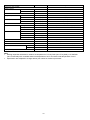
5
Item
Unit
Monobloc Unit
Thermostat
Electronic Control
Protection Device
Electronic Control
Item
Performance Test Condition
Operation Range
Unit
EUROVENT
Outdoor Ambient
Water Outlet
Internal Pressure Differential
Refrigerant Pipe Diameter
Water Pipe Diameter
°C
-20 ~ 35
°C
25 ~ 55
kPa
15.0
Liquid
mm (inch)
9.52 (3/8)
Gas
mm (inch)
15.88 (5/8)
Inlet
mm (inch)
30 (1-3/16)
mm (inch)
30 (1-3/16)
Outlet
Water Drain Hose Inner Diameter
Pump
Water System
mm (inch)
Motor Type
No. of Speed
3
Input Power
Hot Water Coil
W
180
Type
Brazed Plate
No. of Plates
60
Size (W x H x L)
Water Flow Rate
Pressure Relief Valve Water Circuit
mm
93 × 100 × 325
3
l/min (m /h)
25.8 (1.6)
kPa
Open: 190, Close: 186 and below
A
Residual Current Circuit Breaker (40)
Volume
I
10
MWP
bar
1
kW
3.00
Flow Switch
Magnetic Lead Switch
Protection Device
Expansion Vessel
Capacity of Integrated Electric Heater
15.00 (19/32)
Capacitor Run Induction Motor (5 μF)
Note:
Heating capacities are based on outdoor air temperature of 7°C Dry Bulb (44.6°F Dry Bulb), 6°C Wet Bulb
(42.8°F Wet Bulb) with controlled indoor water inlet temperature of 30°C and water outlet temperature of 35°C.
Specification are subjected to change without prior notice for further improvement.
6
2.2
WH-MDF12C9E8
Item
Performance Test Condition
Unit
Heating Capacity
kW
Refrigerant System
EUROVENT
COP
Air Flow
12.00
BTU/h
40900
kcal/h
10320
W/W
4.67
kcal/hW
4.02
3
3
m /min (ft /min)
Refrigeration Control Device
Refrigeration Oil
cm
Refrigerant (R410A)
Pipe Diameter
Compressor
3
FV50S (1200)
kg (oz)
2.30 (81.2)
Liquid
mm (inch)
9.52 (3/8)
Gas
mm (inch)
15.88 (5/8)
Type
Hermetic Motor
Motor Type
Rated Output
Fan
Brushless (4-poles)
kW
4.30
Type
Propeller Fan
Material
PP
Motor Type
Input Power
Output Power
Fan Speed
Heat Exchanger
80.0 (2830)
Expansion Valve
Induction (8-poles)
W
—
W
60
rpm
510 (Top Fan) 550 (Bottom Fan)
Fin material
Aluminium (Pre Coat)
Fin Type
Corrugated Fin
Row × Stage × FPI
Size (W × H × L)
881.5 × 1295.4 × 44
Unit
Monobloc Unit
mm (inch)
1410 (55.5)
Width
mm (inch)
1283 (50.5)
Depth
mm (inch)
320 (12.6)
Net Weight
kg (lbs)
157 (346)
Noise Level
dB-A
50
Dimension
Item
Height
2 × 51 × 18
mm
Power Source (Phase, Voltage, Cycle)
Power Level dB
67
ø
Three
V
400
Hz
50
kW
2.57
Starting Current
A
3.9
Running Current
A
3.9
A/kW
8.8 / 5.85 (Separate ELCB)
A/kW
13.0 / 9.00
A/kW
13.0 / 3.00
Input Power
Max. Current/Max. Input Power Heatpump unit
(Heatpump unit + Back-up Heater)
Back-up Heater: Max. Current/Max. Input Power
Tank Heater [1 Phase, 230V]: Max. Current/
Max. Input Power
Power Factor
%
Power factor means total figure of compressor and outdoor fan motor.
Power Cord
96
Number of core
Length
m (ft)
-
Thermostat
Electronic Control
Protection Device
Electronic Control
7
Item
Performance Test Condition
Operation Range
Unit
EUROVENT
Outdoor Ambient
°C
-20 ~ 35
Water Outlet
°C
25 ~ 55
Internal Pressure Differential
Refrigerant Pipe Diameter
Water Pipe Diameter
Liquid
kPa
27.5
mm (inch)
9.52 (3/8)
Gas
mm (inch)
15.88 (5/8)
Inlet
mm (inch)
30 (1-3/16)
Outlet
Water Drain Hose Inner Diameter
Pump
Water System
mm (inch)
30 (1-3/16)
mm (inch)
15.00 (19/32)
Motor Type
Capacitor Run Induction Motor (5 μF)
No. of Speed
3
Input Power
Hot Water Coil
W
180
Type
Brazed Plate
No. of Plates
60
Size (W x H x L)
Water Flow Rate
Pressure Relief Valve Water Circuit
mm
93 × 100 × 325
3
l/min (m /h)
34.4 (2.1)
kPa
Open: 190, Close: 186 and below
Flow Switch
Magnetic Lead Switch
Protection Device
Expansion Vessel
Volume
MWP
Capacity of Integrated Electric Heater
A
Residual Current Circuit Breaker (40)
I
10
bar
1
kW
9.00
Note:
Heating capacities are based on outdoor air temperature of 7°C Dry Bulb (44.6°F Dry Bulb), 6°C Wet Bulb
(42.8°F Wet Bulb) with controlled water inlet temperature of 30°C and water outlet temperature of 35°C.
Specification are subjected to change without prior notice for further improvement.
8
2.3
WH-MDF14C9E8
Item
Performance Test Condition
Unit
Heating Capacity
kW
Refrigerant System
EUROVENT
COP
Air Flow
14.00
BTU/h
47800
kcal/h
12040
W/W
4.50
kcal/hW
3.87
3
3
m /min (ft /min)
Refrigeration Control Device
Refrigeration Oil
cm
Refrigerant (R410A)
Pipe Diameter
Compressor
3
FV50S (1200)
kg (oz)
2.30 (81.2)
Liquid
mm (inch)
9.52 (3/8)
Gas
mm (inch)
15.88 (5/8)
Type
Hermetic Motor
Motor Type
Rated Output
Fan
Brushless (4-poles)
kW
4.30
Type
Propeller Fan
Material
PP
Motor Type
Input Power
Output Power
Fan Speed
Heat Exchanger
84.0 (2970)
Expansion Valve
Induction (8-poles)
W
—
W
60
rpm
540 (Top Fan) 580 (Bottom Fan)
Fin material
Aluminium (Pre Coat)
Fin Type
Corrugated Fin
Row × Stage × FPI
Size (W × H × L)
881.5 × 1295.4 × 44
Unit
Monobloc Unit
mm (inch)
1410 (55.5)
Width
mm (inch)
1283 (50.5)
Depth
mm (inch)
320 (12.6)
Net Weight
kg (lbs)
157 (346)
Noise Level
dB-A
51
Dimension
Item
Height
2 × 51 × 18
mm
Power Source (Phase, Voltage, Cycle)
Power Level dB
68
ø
Three
V
400
Hz
50
kW
3.11
Starting Current
A
4.7
Running Current
A
4.7
A/kW
9.4 / 6.25 (Separate ELCB)
A/kW
13.0 / 9.00
A/kW
13.0 / 3.00
Input Power
Max. Current/Max. Input Power Heatpump unit
(Heatpump unit + Back-up Heater)
Back-up Heater: Max. Current/Max. Input Power
Tank Heater [1 Phase, 230V]: Max. Current/
Max. Input Power
Power Factor
%
Power factor means total figure of compressor and outdoor fan motor.
Power Cord
96
Number of core
Length
m (ft)
-
Thermostat
Electronic Control
Protection Device
Electronic Control
9
Item
Performance Test Condition
Operation Range
Unit
EUROVENT
Outdoor Ambient
°C
-20 ~ 35
Water Outlet
°C
25 ~ 55
Internal Pressure Differential
Refrigerant Pipe Diameter
Water Pipe Diameter
Liquid
kPa
36.0
mm (inch)
9.52 (3/8)
Gas
mm (inch)
15.88 (5/8)
Inlet
mm (inch)
30 (1-3/16)
Outlet
Water Drain Hose Inner Diameter
Pump
Water System
mm (inch)
30 (1-3/16)
mm (inch)
15.00 (19/32)
Motor Type
Capacitor Run Induction Motor (5 μF)
No. of Speed
3
Input Power
Hot Water Coil
W
180
Type
Brazed Plate
No. of Plates
60
Size (W x H x L)
Water Flow Rate
Pressure Relief Valve Water Circuit
mm
93 × 100 × 325
3
l/min (m /h)
40.1 (2.4)
kPa
Open: 190, Close: 186 and below
Flow Switch
Magnetic Lead Switch
Protection Device
Expansion Vessel
Volume
MWP
Capacity of Integrated Electric Heater
A
Residual Current Circuit Breaker (40)
I
10
bar
1
kW
9.00
Note:
Heating capacities are based on outdoor air temperature of 7°C Dry Bulb (44.6°F Dry Bulb), 6°C Wet Bulb
(42.8°F Wet Bulb) with controlled indoor water inlet temperature of 30°C and water outlet temperature of 35°C.
Specification are subjected to change without prior notice for further improvement.
10
2.4
WH-MDF16C9E8
Item
Performance Test Condition
Unit
Heating Capacity
kW
Refrigerant System
EUROVENT
COP
Air Flow
16.00
BTU/h
54600
kcal/h
13760
W/W
4.23
kcal/hW
3.64
3
3
m /min (ft /min)
Refrigeration Control Device
Refrigeration Oil
cm
Refrigerant (R410A)
Pipe Diameter
Compressor
3
FV50S (1200)
kg (oz)
2.30 (81.2)
Liquid
mm (inch)
9.52 (3/8)
Gas
mm (inch)
15.88 (5/8)
Type
Hermetic Motor
Motor Type
Rated Output
Fan
Brushless (4-poles)
kW
4.30
Type
Propeller Fan
Material
PP
Motor Type
Input Power
Output Power
Fan Speed
Heat Exchanger
90.0 (3180)
Expansion Valve
Induction (8-poles)
W
—
W
60
rpm
580 (Top Fan) 620 (Bottom Fan)
Fin material
Aluminium (Pre Coat)
Fin Type
Corrugated Fin
Row × Stage × FPI
Size (W × H × L)
881.5 × 1295.4 × 44
Unit
Monobloc Unit
mm (inch)
1410 (55.5)
Width
mm (inch)
1283 (50.5)
Depth
mm (inch)
320 (12.6)
Net Weight
kg (lbs)
157 (346)
Noise Level
dB-A
53
Dimension
Item
Height
2 × 51 × 18
mm
Power Source (Phase, Voltage, Cycle)
Power Level dB
70
ø
Three
V
400
Hz
50
kW
3.78
Starting Current
A
5.7
Running Current
A
5.7
A/kW
9.9 / 6.59 (Separate ELCB)
A/kW
13.0 / 9.00
A/kW
13.0 / 3.00
Input Power
Max. Current/Max. Input Power Heatpump unit
(Heatpump unit + Back-up Heater)
Back-up Heater: Max. Current/Max. Input Power
Tank Heater [1 Phase, 230V]: Max. Current/
Max. Input Power
Power Factor
%
Power factor means total figure of compressor and outdoor fan motor.
Power Cord
96
Number of core
Length
m (ft)
-
Thermostat
Electronic Control
Protection Device
Electronic Control
11
Item
Performance Test Condition
Operation Range
Unit
EUROVENT
Outdoor Ambient
°C
-20 ~ 35
Water Outlet
°C
25 ~ 55
Internal Pressure Differential
Refrigerant Pipe Diameter
Water Pipe Diameter
Liquid
kPa
47.5
mm (inch)
9.52 (3/8)
Gas
mm (inch)
15.88 (5/8)
Inlet
mm (inch)
30 (1-3/16)
Outlet
Water Drain Hose Inner Diameter
Pump
Water System
mm (inch)
30 (1-3/16)
mm (inch)
15.00 (19/32)
Motor Type
Capacitor Run Induction Motor (5 μF)
No. of Speed
3
Input Power
Hot Water Coil
W
180
Type
Brazed Plate
No. of Plates
60
Size (W x H x L)
Water Flow Rate
Pressure Relief Valve Water Circuit
mm
93 × 100 × 325
3
l/min (m /h)
45.9 (2.8)
kPa
Open: 190, Close: 186 and below
Flow Switch
Magnetic Lead Switch
Protection Device
Expansion Vessel
Volume
MWP
Capacity of Integrated Electric Heater
A
Residual Current Circuit Breaker (40)
I
10
bar
1
kW
9.00
Note:
Heating capacities are based on outdoor air temperature of 7°C Dry Bulb (44.6°F Dry Bulb), 6°C Wet Bulb
(42.8°F Wet Bulb) with controlled water inlet temperature of 30°C and water outlet temperature of 35°C.
Specification are subjected to change without prior notice for further improvement.
12
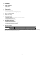
3. Features
Inverter Technology
- Energy saving
High Efficiency
Compact Design
Environment Protection
- Non-ozone depletion substances refrigerant (R410A)
Easy to use remote control
Weekly Timer setting
Quality Improvement
-
Serviceability Improvement
-
Random auto restart after power failure for safety restart operation
Gas leakage protection
Prevent compressor reverse cycle
Inner protector to protect compressor
Breakdown Self Diagnosis function
System Status Check Buttons for servicing purpose
System Pumpdown Button for servicing purpose
Front maintenance design for monobloc unit
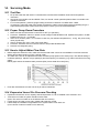
Operation Condition
HEATING
Maximum
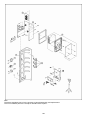
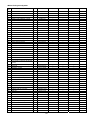
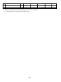
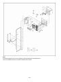
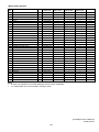
Minimum
Water outlet temperature (°C)
55
25
Ambient temperature (°C)
35
-20
NOTICE : When the outdoor temperature is out of the above temperature range, the heating capacity will drop significantly
and monobloc unit might stop for protection control.
13
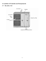
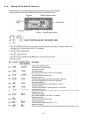
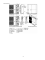
4. Location of Controls and Components
4.1
Monobloc Unit
14
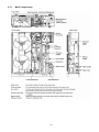
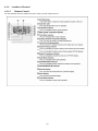
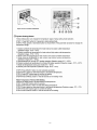
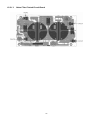
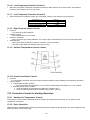
4.1.1
Main Components
15
4.1.2
4.1.2.1
Location of Control
Remote Control
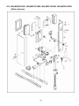
The user interface allows the installer and user to setup, use and maintain the unit.
16
17
18
4.1.3
Weekly Timer Setting
19
4.1.4
Setting Up The Special Functions
20
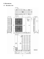
5. Dimensions
5.1
Monobloc Unit
21
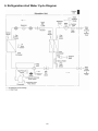
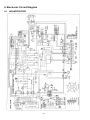
6. Refrigeration And Water Cycle Diagram
22
23
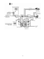
7. Block Diagram
7.1
WH-MDF09C3E8
24
7.2
WH-MDF12C9E8 WH-MDF14C9E8 WH-MDF16C9E8
25
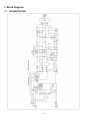
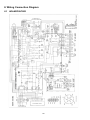
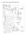
8. Wiring Connection Diagram
8.1
WH-MDF09C3E8
26
27
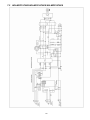
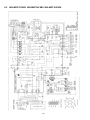
8.2
WH-MDF12C9E8 WH-MDF14C9E8 WH-MDF16C9E8
28
29
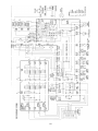
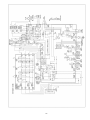
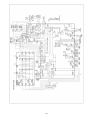
9. Electronic Circuit Diagram
9.1
WH-MDF09C3E8
30
31
9.2
WH-MDF12C9E8 WH-MDF14C9E8 WH-MDF16C9E8
32
33
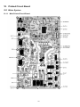
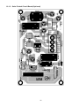
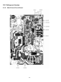
10. Printed Circuit Board
10.1 Water System
10.1.1 Main Printed Circuit Board
34
10.1.2 Solar Printed Circuit Board (Optional)
35
10.2 Refrigerant System
10.2.1 Main Printed Circuit Board
36
10.2.1.1
Noise Filter Printed Circuit Board
37
11. Installation Instruction
Monobloc Unit
Dimension Diagram
38
Main Components
39
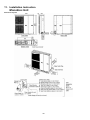
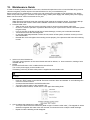
11.1 Select the Best Location
11.2 Monobloc Unit Installation
Install Monobloc unit at outdoor only.
Avoid location where ambient temperature is
below -20°C.
Must install on a flat horizontal and solid hard
surface.
A place where should not be any heat source or
steam near the Monobloc unit.
A place where air circulation is good.
A place where drainage can be easily done.
A place where Monobloc unit’s operation noise
will not cause discomfort to the user.
A place where accessible for maintenance.
Ensure to keep minimum distance of spaces as
illustrated below from wall, ceiling, or other
obstacles.
A place where flammable gas leaking might not
occur.
A place where the Monobloc unit’s piping and
wiring lengths come within reasonable ranges.
If an awning is built over the unit to prevent direct
sunlight or rain, be careful that heat radiation from
the condenser is not obstructed.
Do not place any obstacles which may cause a
short circuit of the discharged air.
Avoid install the Monobloc unit at a location where
suction side may be exposed directly to wind.
If Monobloc unit installed near sea, region with
high content of sulphur or oily location (e.g.
machinery oil, etc.), it lifespan maybe shorten.
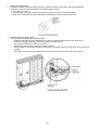
When installing the product in a place
where it will be affected by typhoon or
strong wind such as wind blowing
between buildings, including the
rooftop of a building and a place
where there is no building in
surroundings, fix the product with an
overturn prevention wire, etc.
(Overturn prevention fitting model
number: K-KYZP15C)
When connecting solar pump station cable
between Monobloc unit and solar pump station,
the distance between both apparatuses shall be
2 ~ 8 meters and the length of the said cable must
be shorter than 10 meters.
Fail to do so may lead to abnormal operation to
the system.
Monobloc unit will become heavy when filled with
water.
Therefore, please install the Monobloc unit on strong
concrete floor, by considering weight of unit and water.
Fix Mono bloc unit on the concrete floor with M12
anchor bolt at 4 locations.
Pull-out strength of these anchor bolts must be
above 15000N.
40
11.3 Piping Installation
WARNING
This section is for authorized and licensed electrician / water
system installer only. Work behind the front plate secured by
screws must only be carried out under supervision of qualified
contractor, installation engineer or service person.
Please engage a licensed water circuit installer to install this
water circuit.
The minimum requirement of water in the system is 50
litres.If this value could not be achieved, please install
additional buffer tank (field supply).
This water circuit must comply with relevant European
and national regulations (including EN61770), and local
building regulation codes.
Ensure the components installed in the water circuit could
withstand water pressure during operation.
Do not apply excessive force to piping that may damage
the pipes.
Do not install any valve between Monobloc unit and water
piping to avoid accidental closure of water supply to the
Monobloc unit.
Use Rp 1 ¼” nut for both water inlet and water outlet
connection and clean all piping with tap water before
install.
If old heat pump terminal / tank is utilized, please clean
the dust properly before installation.
Refer Diagram 3.1 for installation of 3-way Valve Kit.
Must install an external filter (30 mesh or more, field
supply) before water inlet connector of Monobloc unit
(indicate with “WATER IN”).
Connect the external of Monobloc unit (indicate with
“WATER OUT”) to boiler tank inlet. Fail to connect the
tube appropriately might causing the Monobloc unit
malfunction.
Choose proper sealer which can withstand the pressures
and temperatures of the system.
Make sure to use two spanners to tighten the connection.
Further tighten the nuts with torque wrench in specified
torque as stated in the table.
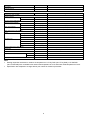
Model
Nut size (Torque)
Water
WH-MDF09C3E5
WH-MDF12C6E5
WH-MDF14C6E5
Rp 1 1/4" [117.6 N•m]
WH-MDF16C6E5
If non-brass metallic piping is used for installation, make
sure to insulate the piping to prevent galvanic corrosion.
Do not use worn out piping.
Make sure to insulate the water circuit piping (insulator
thickness : 20mm or more) to prevent reduction of heating
capacity, as well as avoid freezing of the outdoor water
circuit piping during winter season.
After installation, check the water leakage condition in
connection area during test run.
Drainage piping installation
Use a drain hose with inner diameter of 15 mm.
The hose must be installed in a continuously downward
direction and left open to the frost-free atmosphere.
If drain hose is long, use a metal support fixture along the
way to eliminate the wavy pattern of drain tube.
The water may drip from this discharge hose. Therefore
must guide the hose without close or block the outlet of
the hose.
Do not insert this hose into sewage hose or cleaning hose
that may generate ammonia gas, sulfuric gas, etc.
If necessary, use a hose clamp to tighten the hose at
drain hose connector to prevent it from leaking.
In case of a power supply failure or pump operating failure,
drain the system (as suggested in the figure below)
When water is idle inside the system, freezing up is very
likely to happen which could damage the system
41
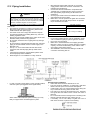
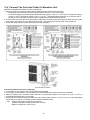
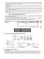
11.4 Connect The Cord And Cable To Monobloc Unit
(REFER TO WIRING DIAGRAM AT UNIT FOR DETAIL)
1. Cable connection to the power supply through isolating device (Disconnecting means).
Isolating device (Disconnecting means) should have minimum 3.0 mm contact gap.
2
Connect the approved polychloroprene sheathed power supply 1 cord (3 x 4.0 or 6.0 mm ) and power supply 2
2
2
cord (3 x 4.0 mm ) and power supply 3 cord (3 x 1.5 mm ), type designation 60245 IEC 57 or heavier cord to
the RCCB, and to the other end of the cord to isolating device (Disconnecting means).
2. To avoid cable and cord harmed by sharp edge, cable and cord must go through bushing (located at the right side
of Monobloc unit) before carry out electrical connection. The bushing must be used and must not take off.
3. Secure the cable onto the control board with the holder (clamper).
Connecting with external device (optional)
1. All connections shall follow to the local national wiring standard.
2. It is strongly recommended to use manufacturer-recommended parts and accessories for installation.
3. Maximum output power of booster heater shall be ≤ 3 kW. Booster Heater’s cord must be (3 x min 1.5 mm2), of
type designation 60245 IEC 57 or heavier.
4. Three-way Valve shall be spring and electronic type. Valve’s cable shall be (3 x min 0.5 mm2), of type designation
60245 IEC 57 or heavier, or similarly double insulation sheathed cable.
* note: - Shall be CE marking compliance component.
- It shall be directed to heating mode when it is OFF.
- Maximum load for the valve is 3VA.
42
5. Receiver shall be connected to “Room Thermostat”, refer to “Field Supply Accessories” table for details.
Receiver’s cable must be (4 or 3 x min 0.5 mm2), double insulation layer of PVC-sheathed or polychloroprene
sheathed cable. (connection refer to Diagram 4.2).
6. Tank OLP’s cable must be (2 x min 0.5 mm2), double insulation layer of PVCsheathed or polychloroprene
sheathed cable.
* note: if such connection deemed NO necessary for tank OLP, please connect jumper between terminal no
#13 and #14.
7. Tank Sensor shall be resistance type, please refer to Graph 4.1 for the characteristic and details of sensor. Its
cable shall be (2 x min 0.3 mm2), double insulation layer (with insulation strength of min 30V) of PVC-sheathed
or polychloroprene sheathed cable.
8. External Controller shall be connected to 1-pole switch with min 3.0mm contact gap. (connection refer to
Diagram 4.3). Its cable must be (2 x min 0.5 mm2), double insulation layer of PVC-sheathed or polychloroprene
sheathed cable.
* note: - When making such connection, kindly remove the jumper between terminal no #17 and #18.
- Switch used shall be CE compliance component.
- Maximum operating current shall be less than 3Arms.
9. Solar Three-way Valve’s cable shall be (3 x min 0.5 mm2), double insulation layer PVC-sheathed or
polychloroprene sheathed cable.
to Monobloc unit when Solar Pump Station is utilized. Refer Solar
10. Must install Solar Connection PCB
Connection PCB’s installation instruction for detail of installation.
11. Solar Pump Station’s cable shall be (2 x min 0.5 mm2), of double insulation PVC-sheathed or polychloroprene
sheathed cable. Strongly recommended install with maximum length of 10 meter only.
Terminal screw
Tightening torque N•cm {kgf•cm}
M4
157~196 {16~20}
M5
196~245 {20~25}
11.4.1 Wire Stripping And Connecting Requirement
11.4.2 Connecting Requirement
For WH-MDF09C3E5:
The equipment’s power supply 1 complies with IEC/EN 61000-3-12 provided that the short-circuit power Ssc is greater than or
equal to 858kW (for WH-MDF09C3E5) at the interface point between the user’s supply and the public system. It is the
responsibility of the installer or user of the equipment to ensure, by consultation with the distribution network operator if
necessary, that the equipment is connected only to a supply with a short-circuit power Ssc greater than or equal to 858kW.
43
The equipment’s power supply 1 shall be connected to a suitable supply network, having service current capacity ≥100A per
phase. Please liaise with supply authority to ensure that the service current capacity at the interface point is sufficient for the
installation of the equipment.
The equipment’s power supply 2 complies with IEC/EN 61000-3-12.
The equipment’s power supply 2 shall be connected to a suitable supply network, with the following maximum permissible
system impedance Zmax at the interface for models:
WH-MDF09C3E5 : 0.236Ω
Please liaise with supply authority to ensure that the power supply 2 is connected only to a supply of that impedance or less.
For WH-MDF12C6E5, WH-MDF14C6E5, WH-MDF16C6E5:
The equipment’s power supply 1 complies with IEC/EN 61000-3-12 provided that the short-circuit power Ssc is greater than or
equal to 858kW (for WH-MDF12C6E5, WH-MDF14C6E5, WH-MDF16C6E5) at the interface point between the user’s supply
and the public system. It is the responsibility of the installer or user of the equipment to ensure, by consultation with the
distribution network operator if necessary, that the equipment is connected only to a supply with a short-circuit power Ssc
greater than or equal to 858kW.
The equipment’s power supply 1 shall be connected to a suitable supply network, having service current capacity ≥100A per
phase. Please liaise with supply authority to ensure that the service current capacity at the interface point is sufficient for the
installation of the equipment.
The equipment’s power supply 2 complies with IEC/EN 61000-3-12.
The equipment’s power supply 2 shall be connected to a suitable supply network, with the following maximum permissible
system impedance Zmax at the interface for models:
WH-MDF12C6E5, WH-MDF14C6E5, WH-MDF16C6E5 : 0.236 Ω
Please liaise with supply authority to ensure that the power supply 2 is connected only to a supply of that impedance or less.
The equipment’s power supply 3 complies with IEC/EN 61000-3-12.
The equipment’s power supply 3 shall be connected to a suitable supply network, with the following maximum permissible
system impedance Zmax at the interface for models:
WH-MDF12C6E5, WH-MDF14C6E5, WH-MDF16C6E5 : 0.464 Ω
Please liaise with supply authority to ensure that the power supply 3 is connected only to a supply of that impedance or less.
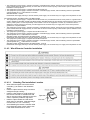
11.4.3 Wired Remote Controller Installation
11.4.3.1
Selecting The Installation Location
Allow sufficient space around the remote
controller (1) as shown in the illustration
above.
Install in a place which is away from direct
sunlight and high humidity.
Install in a flat surface to avoid warping of
the remote controller. If installed to a wall
with an uneven surface, damage to the LCD
case or operation problems may result.
Install in a place where the LCD can be
easily seen for operation. (Standard height
from the floor is 1.2 to 1.5 meters.)
Avoid installing the remote controller cable
near refrigerant pipes or drain pipes, else
it will cause electrical shock or fire.
44
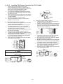
11.4.3.2
1.
2.
3.
4.
5.
Installing The Remote Controller Unit To The Wall
Remove the remote controller (1) lower case.
(Insert a flat-tipped screw driver or similar tool 2 to 3
mm into one of the gaps at the bottom of the case, and
twist to open. Refer to the illustration at right.)
Be careful not to damage the lower case.
Do not remove the protective tape which is affixed to
the upper case circuit board when remove the remote
controller lower case.
Secure the lower case to an outlet box or wall. Refer to
(A) or (B) instructions below depending on your choice
of cable installation.
Be sure to use only the screws provided.
Do not over tighten the screws, as it may result in
damage to the lower case.
B.
A. If Remote Controller Cable Is Embedded
1.
Embed an outlet box (JIS C 8336) into the wall. Outlet
box may be purchased separately.
Medium-sized square outlet box (obtain locally) Part
No. DS3744 (Panasonic Co., Ltd.) or equivalent.
2.
Secure the remote controller lower case to the outlet
box with the two accessory screws (3).
Make sure that the lower case is flat against the wall at
this time, with no bending.
3.
Pass the remote controller cable (2) into the box.
4.
Route the remote controller cable (2) inside the lower
case through rear feeding-out direction.
5.
Insert firmly the connector of remote controller cable (2)
to connector (CON1) in the upper case circuit board.
[Refer to the illustration at below.]
6.
Secure the remote controller upper case to the lower
case with the tabs provided.
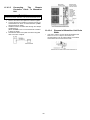
If Remote Controller Cable Is Exposed
1. Install the remote controller lower case to the wall
with the two accessory screws (4).
2. Fasten the screws properly until screw head is lower
than the rib and reach the base of remote controller
lower case to ensure they do not damage the PCB
inside the remote controller (1).
3.
The feeding-out direction for the remote controller
cable can be either via top, left or right side.
4. Use nipper to cut a notch at the upper case. (Select
the intended feeding-out position)
5. Route the remote controller cable (2) inside the
lower case in accordance with the intended feedingout direction. (Refer to the illustration at below)
6. Insert firmly the connector of remote controller cable
(2) to connector (CON1) in the upper case circuit
board (Refer to the illustration at below)
7. Secure the remote controller upper case to the lower
case with the tabs provided.
When the wall is hollow, please be sure to use the sleeve for
remote controller cable to prevent dangers caused by mice
biting the cable.
45
11.4.3.3
Connecting
The
Remote
Controller Cable To Monobloc
Unit
Be sure to turn off the main power before installing and connecting
the remote controller. Otherwise, it will cause the electrical shock.
1. Remove the cabinet front plate and cabinet top plate.
2. Connect the remote controller’s connector to PCB CN-REMOTE2 as shown in below illustration. (Refer
wiring diagram for detail.)
3. Guide the remote controller cable through the clamper
and Bushing .
(Refer illustration “How to connect Remote Controller
to PCB” for detail.)
4. Reinstall the cabinet front plate and cabinet top plate
after connection complete.
11.4.3.4
46
Disposal of Monobloc Unit Drain
Water
If the unit is used in an area where temperature falls
below 0°C for 2 or 3 days in succession, it is
recommended not to use a drain elbow, for the drain
water freezes and the fan will not rotate.
12. Operation and Control
12.1 Basic Function
Inverter control, which equipped with a microcomputer in determining the most suitable operating mode as time
passes, automatically adjusts output power for maximum comfort always. In order to achieve the suitable operating
mode, the microcomputer maintains the set temperature by measuring the temperature of the environment and
performing temperature shifting. The compressor at monobloc unit is operating following the frequency instructed
by the microcomputer at monobloc unit that judging the condition according to internal water setting temperature
and water outlet temperature.
12.1.1 Internal Water Setting Temperature
Once the operation starts, control panel setting temperature will be taken as base value for temperature shifting
processes. These shifting processes are depending on the monobloc unit settings and the operation environment.
The final shifted value will be used as internal water setting temperature and it is updated continuously whenever
the electrical power is supplied to the unit.
12.1.2 Heating Operation
12.1.2.1
Thermostat control
Compressor is OFF when Water Outlet Temperature - Internal Water Setting Temperature > 2°C for continuously
3 minutes.
Compressor is ON after waiting for 3 minutes, if the Water Outlet Temperature - Water Inlet Temperature
(temperature at thermostat OFF is triggered) < -3°C.
12.1.3 Tank Mode Operation
Control contents:
3 ways valve direction
- 3 ways valve switch and fix to tank side.
Heatpump Thermostat characteristic
- Water set temperature = Tank set temperature or [55°C] whichever lower.
- Heatpump Water Outlet set temperature is set to Maximum (55°C) at tank mode
i. Case 1
- THERMO OFF TEMP:
1 THERMO OFF TEMP = Water set temperature + [+2°C].
2 Tank temperature > THERMO OFF TEMP for continuous 3 minutes, heatpump OFF and water pump OFF.
- THERMO ON TEMP:
1 THERMO ON TEMP = Water set temperature + [-3°C].
2 When detect tank temperature < THERMO ON TEMP, water pump ON for 3 minute then heatpump ON.
- Pump ON when Tank temperature is less than tank temperature when Heatpump Thermo Off - [-3°C].
47
ii. Case 2
- Heatpump THERMO OFF TEMP:
1 Heatpump THERMO OFF TEMP = 55°C + [+2°C].
2 Water outlet temperature > Heatpump THERMO OFF TEMP for continuous 3 minutes, heatpump OFF
but water pump ON.
- Heatpump THERMO ON TEMP:
1 Heatpump THERMO ON TEMP = Water inlet during thermo off time + [-3°C].
2 Heatpump ON back when water outlet temperature < Heatpump THERMO ON TEMP.
iii. Case 3
- Heatpump THERMO OFF TEMP:
1 Water inlet temperature > 52°C for continuous 60 seconds, heatpump OFF and water pump OFF.
- Heatpump THERMO ON TEMP:
1 Heatpump THERMO ON TEMP = Water inlet during thermo off time + [-3°C].
2 Water pump ON back when tank temp. < Tank temp. when heatpump thermo off + [-3°C].
3 Heatpump only ON back after water outlet temperature < Heatpump THERMO ON TEMP & water pump
ON for 3 minutes.
Booster heater control
- Booster heater turn On and Off follow normal operation.
- Booster heater turn ON condition:
1 During startup time (initialization), Booster heater turn ON after DELAY TIMER.
2 When tank temperature lower than HEATER ON TEMP
3 20 minutes from previous heater off.
- Booster heater turn OFF condition:
1 When tank temperature higher than tank set temperature for continous 15 sec.
Solar 3 way valve
- Solar pump operates follow solar operation specification.
Others
- Indoor backup heater cannot be ON during tank mode only.
48
12.1.4 Heat + Tank Mode Operation
Setting 1: When Heating priority is set by control panel:
1 3 ways valve control:
o 3 ways valve switch and fix to room side.
2
Heatpump operation control:
o Heatpump operate follow normal operation.
3
Backup Heater control:
o Backup heater operate follow normal operation.
4
Booster heater control:
o Booster heater On/Off follow normal operation.
5
Solar 3 way valve:
o Solar 3 way valve operates follow solar operation specification.
* Under solar priority is set condition, when solar 3 way valve is ON, booster heater turn OFF.
Setting 2: When heating priority is not set by control panel:
When Solar Priority is set/not set by control panel:
1 3 ways valve control:
o 3 ways valve switch to room side during heating heat-up interval, and switch to tank side during tank
heat-up interval. Both mode will switch alternatively.
2
Heatpump operation control:
o During heating heat-up interval
- Follow normal heating operation.
Under solar priority set condition:
- Always detect the tank temperature after heating heat-up interval. Switch only to tank heat-up
interval and start counting tank heat-up timer when tank temperature < THERMO ON TEMP AND
solar 3WV OFF
Under solar priority not set condition:
- Always detect the tank temperature after heating heat-up interval. Switch only to tank heat-up
interval and start counting tank heat-up timer when tank temperature < THERMO ON TEMP
* THERMO ON TEMP is defined form following Case1 to Case4.
o During tank heat-up interval
- Heatpump tank target temperature = Tank set temperature or [55°C] whichever lower
- Heatpump Water Outlet set temperature is set to Maximum [55°C] during tank interval
49
i. Case 1
- THERMO OFF TEMP:
1. THERMO OFF TEMP = Heatpump tank target temperature + [+2°C].
2. Tank temperature > THERMO OFF TEMP for continuous 3 minutes, switch 3 ways valve to room side.
End Tank heat-up interval and start count heating heat-up interval.
- THERMO ON TEMP:
1. THERMO ON TEMP = Heatpump tank target temperature + [-3°C].
2. After Heating heat-up interval, always detect tank temperature. Switch to next tank heat-up interval
when tank temperature < THERMO ON TEMP
ii. Case 2
- Heatpump THERMO OFF TEMP:
1. Heatpump THERMO OFF TEMP = 55°C + [+2°C].
2. Water outlet temperature > Heatpump THERMO OFF TEMP for continuous 90 seconds, switch
3 ways valve to room side. End Tank heat-up interval and start count heating heat-up interval.
- THERMO ON TEMP:
1. THERMO ON TEMP = Tank temp. when heatpump thermo off + [-3°C].
2. After Heating heat-up interval, always detect tank temperature. Switch to next tank heat-up interval
when tank temperature < THERMO ON TEMP
iii. Case 3
- Heatpump THERMO OFF TEMP:
1. Water inlet temperature > 52°C for continuous 60 seconds, switch 3 ways valve to room side. End
tank heat-up interval and start count heating heat-up interval.
- THERMO ON TEMP:
1. THERMO ON TEMP = Tank temp. when heatpump thermo off + [-3°C].
2. After Heating heat-up interval, always detect tank temperature. Switch to next tank heat-up interval
when tank temperature < THERMO ON TEMP
iv. Case 4 (Only during solar priority is set condition)
When solar pump ON, tank heat-up interval end early and 3 ways valve switch to room side.
- THERMO ON TEMP:
1. THERMO ON TEMP = Heatpump tank target temperature + [-3°C].
2. After Heating heat-up interval, always detect tank temperature. Switch to next tank heat-up interval
when tank temperature < THERMO ON TEMP and solar 3 way valve OFF.
3
Backup heater control:
o During heating heat up interval.
- Follow normal backup heater control operation.
o During tank heat-up interval.
- Backup heater OFF during this interval.
4
Booster heater control:
o During heating heat-up interval.
- Booster heater ON/OFF according to booster heater operation control.
o During tank heat-up interval.
- Once switch from heating heat-up interval to tank heat-up interval, turn off the booster heater and start
counting the BOOSTER HEATER DELAY TIMER.
- Booster heater turn ON after BOOSTER HEATER DELAY TIMER fufil and tank temperature lower
than tank set temperature.
- BOOSTER HEATER DELAY TIMER is clear when switch to heating heat-up interval.
5
Solar 3 way valve:
o Solar 3WV operates follow solar operation specification.
50
* Under solar priority is set condition, when solar 3WV is ON, booster heater turn OFF.
* Under solar priority is not set condition, solar 3WV only can ON during heating heat-up interval.
51
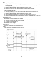
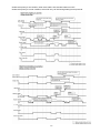
12.1.5 Setting Water Outlet Temperature for Heat Mode
The set temperature define the parameters for the outdoor ambient temperature dependent operation of the unit.
Where by the internal water setting temperature is determined automatically depending on the outdoor
temperature. The colder outdoor temperatures will result in warmer water and vice versa. The user has the
possibility to shift up or down the target water temperature by remote control setting.
Water
Temp.
OUT LO = Low outdoor ambient set temperature
OUT HI = High outdoor ambient set temperature
H2O LO = Water outlet set temperature at low outdoor ambient temperature
H2O HI = Water outlet set temperature at high outdoor ambient temperature
H2O LO
H2O HI
OUT HI
OUT LO
• Change in setting water outlet temperature is updated every 30 minutes
Outdoor temperature is updated every 30 minutes when operation ON.
12.1.5.1
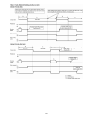
Heating Mode Operation Time Chart
Example
1
2
3
4
3 ways valve control:
o 3 ways valve switch and fix to heating side.
Heatpump operate follow normal heating operation.
Backup heater operate follow normal operation.
Solar 3 way valve operates follow solar operation specification.
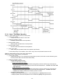
12.1.6 Water Temperature Thermo Shift Setting
Switchs are ignored during “PUMPDW” = ON.
Switchs are ignored during “STATUS” = ON.
52
Outdoor
Temp.
“▲”, “▼”, “SELECT” switch are ignored if “SETTING” = OFF.
“CANCEL” switch is ignored if “SETTING” = OFF & “STATUS” = OFF.
If “SET” Switch pressed for less than 5secs, immediately enter water temperature shift setting mode.
Once enter this setting mode, “SETTING” display is ON.
This setting mode is used to easily shift the target water outlet temperature.
Water
Temp.
H2O LO
+5
H2O HI
Shift value
±0
-5
OUT HI
OUT LO
Outdoor
Temp.
OUT LO = Low outdoor ambient set temperature
OUT HI = High outdoor ambient set temperature
H2O LO = Water outlet set temperature at low outdoor ambient temperature
H2O HI = Water outlet set temperature at high outdoor ambient temperature
Shift Value = Setting water temperature thermo shift
12.1.7 Fan Motor Operation
Fan motor is adjusted according to operation condition. It starts when compressor starts operation and it stops 30
seconds after compressor stops operation.
53
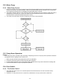
12.2 Water Pump
12.2.1 Water Pump Control
1
2
3
Once the monobloc unit is ON, the water pump will be ON immediately and no error judgement for 9 minutes.
However, during this 9 minutes operation, if there is any abnormality cause at monobloc unit or malfunction,
the compressor should be OFF immediately and restart delay after 3 minutes.
The system will start checking on the water flow level after operation start for 9 minutes. If water flow level is
detected low continuously for 1 minute, the water pump and compressor will be OFF permanently and
OFF/ON remote control LED will blink (H62 error occurs)
The water pump will remain ON when compressor OFF due to thermostat OFF.
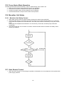
12.3 Pump Down Operation
Purpose
Ensure the pump down operation when relocating or disposing of the unit. The pump down operation will extract
all refrigerant from the piping into the outdoor unit.
1
2
3
4
Make sure the OFF/ON control panel LED is OFF (no operation).
Press the Pump Down button to start the pump down operation.
No low pressure protection error during pump down operation and 3-way valve will be shift to heating side.
Press OFF/ON button to stop the pump down operation.
12.4 Flow Switch
12.4.1 Flow Switch Control
1
2
The water flow switch serve as an overload protector that shuts down the unit when the water level is
detected to be low.
Detection is Lo (0V) when there is no water flow, and detection is Hi (5V) when there is water flow.
54
12.5 Force Heater Mode Operation
The backup heater also serves as backup in case of malfunctioning of the outdoor unit.
1 Make sure the OFF/ON control panel LED is OFF (no operation).
2 Press the Force button to start the force heater mode operation.
3 During force heater mode, all other operations are not allowed.
4 Press OFF/ON button to stop the force heater mode operation.
12.6 Monobloc Unit Safety
12.6.1 Monobloc Unit Safety Control
1
2
3
When water pump is ON, the system will start checking flow switch status (ON/OFF).
If the flow switch ON for 10 seconds, the system will check on the water inlet temperature for 10 seconds.
If the water inlet temperature not exceeds 80°C, the water pump shall be continuously running with normal
mode.
If the water inlet temperature exceeds 80°C for continuously 10 seconds, the water pump will be OFF
immediately.
After water pump OFF for more than 10 minutes, it will be ON back and the monobloc unit safety control
checking is restarted.
12.7 Auto Restart Control
1
When the power supply is cut off during the operation of Monobloc unit, the compressor will re-operate after
power supply resumes.
55
12.8 Indication Panel
LED
Color
Light ON
Light OFF
Operation
Green
Operation ON
Operation OFF
Note:
If Operation LED is blinking, there is an abnormality operation occurs.
12.9 Back-Up Heater Control
12.9.1 Electric Heater Control
1
Normal Heating Mode
o Heater On condition:
a. Heater switch is ON
b. After Heatpump thermo ON for [30] mins
c. After water pump operate [9] mins
d. Outdoor air temperature < Outdoor set temperature for heater
e. When water outlet temperature < Water set temperature + [-8°C]
f. [20] minutes since previous Backup heater Off
* When heatpump cannot operate due to error happens during normal operation, heater will go into
force mode automatic
* Heater need to operate during deice operation
o
2
Heater Stop Condition:
a. When outdoor set temperature > outdoor set temperature + [+2°C] for continuous 15 secs OR
b. When water out temp> water set temperature + [-2°C] for continuous 15 secs OR
c. Heater switch is Off OR
d. Heatpump thermo-off or OFF condition
Force Heater Mode
o Heater On Condition:
a. After water pump operate [9] mins
b. When water outlet temperature < water set temperature + [-8°C]
c. [20] minutes since previous Backup heater Off
o
Heater Stop condition
a. Force mode off OR
b. When water outlet temperature > water set temperature + [-2°C] for continuous 15 secs
* Do not operate heater at the following situation
1 Water outlet temperature sensor, and water inlet sensor abnormal
2 Flow switch abnormal
3 Circulation pump stop condition
4 During Heatpump switch to tank side
56
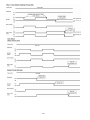
12.10 Tank Booster Heater Control
12.10.1 Tank booster heater control
Heating operation condition:
1
2
Booster heater Turn On condition:
o After BOOSTER HEATER DELAY TIMER fulfil during heatpump startup time in tank mode, or during
switching from heating heat-up interval to tank heat-up interval in heat+tank mode (heating priority not
set).
o Tank temperature < tank set temperature + [-5°C],
o 20 minutes since previous heater off.
* BOOSTER HEATER DELAY TIMER is clear when tank heat-up interval end.
Booster heater Turn Off condition:
o Tank temperature > Tank set temperature + [+2°C] for continuous 15 sec
o When BOOSTER HEATER DELAY TIMER start count after switch from heating heat-up interval to tank
heat-up interval
* DELAY TIMER can be set by control panel.
12.11 Three Way Valve Control
Purpose:
- 3 ways valve is used to change flow direction of hot water from heatpump between heating side and tank side
Control contents:
1 3 ways valve switch Off:
o During 3 ways valve switch Off time, the hot water will provide heat capacity to heating side.
2 3 ways valve switch On:
o During 3 ways valve switch On time, the hot water will provide heat capacity to tank side.
3 Stop condition:
o During stop mode, 3 ways valve will be in switch off position
12.12 Sterillization Mode
1
2
3
4
During sterillization mode, Tank will be heat up to the sterillize Set temperature for a certain period of time,
also set by controller.
The function can only be set on timer to operate once in a week.
It will be cancelled even when the temperature is not reached after 4 hours.
When tank mode is OFF or disabled, sterillization is cancelled.
12.13 Quiet Operation
Purpose:
- To provide quiet operation compare to normal operation by reduces outdoor unit noise.
Starting condition:
1 When quiet button is presses.
2 When quiet request ON time by weekly timer (Refer to remote control.)
When any of above mentioned condition is achieved, this control is activated.
New target FM speed = Present target FM speed - 80rpm
Minimum target FM speed = 200rpm
Cancellation condition:
1
2
3
Cancel by press quiet button
Stop by OFF/ON button
When quiet request OFF time by weekly timer
When any of above mentioned condition is achieved, this control is cancelled.
57
12.14 Solar Operation (Optional)
12.14.1 Solar Operation
1
2
3
Control according to preset whether solar priority is set or not.
When tank connection is NOT set at SETTING mode, Solar operation is disabled.
When Pump A (from Solar pump station) is detected On through connection Y3 and Y4, then the Solar pump
3 Way Valve is requested ON (Refer to figure below).
12.14.2 Solar Operation Control
When solar priority is SET
1 Operation condition:
a
Solar pump operates if all of the following conditions are fulfilled: Power On. (regardless operation ON or OFF)
There is operation request from Solar pump station.
Tank hot water temp is below solar on upper limit temp [EEPROM 1 : 70]°C.
2 Stop condition:
a
Solar pump stops operating when: No power supply to unit OR
There is NO operation request from solar pump station OR
Tank hot water temp is above solar off upper limit temp [EEPROM 2 : 77]°C.
* heatpump OFF OR operate to room side when solar pump operate during solar priority set.
* booster heater OFF when solar pump operate during solar priority set.
When solar priority is NOT SET
1 Operation condition:
a
Solar pump operates if all of the following conditions are fulfilled: Power On. (regardless operation ON or OFF).
There is operation request from Solar pump station.
Tank hot water temp is below solar on upper limit temp [EEPROM 1 : 70]°C.
Heatpump thermo OFF in tank mode OR Heatpump operate to room side
(During Operation ON and tank mode selected).
2 Stop condition:
a
Solar pump stops operating when: No power supply to unit OR
There is NO operation request from solar pump station OR
Tank hot water temp is above solar off upper limit temp [EEPROM 2 : 77]°C.
Heatpump thermo ON and operate to tank side. (During Operation ON and tank mode selected).
58
59
60
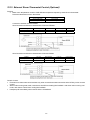
12.15 External Room Thermostat Control (Optional)
Purpose:
1 Better room temperature control to fulfill different temperature request by external room thermostat.
Recommended external room thermostat:
Maker
Siemen (REV200)
Siemen (RAA20)
Characteristic
Touch panel
Analog
Connection external room thermostat:
Wire Connection and thermo characteristic of Siemen REV200:
Setting
Set Temp < Actual Temp
Set Temp > Actual Temp
L/L1 (H)
Open Circuit
Short Circuit
Heat Thermo
OFF
ON
L/L2 (C)
Short Circuit
Open Circuit
Cool Thermo
ON
OFF
Wire Connection and thermo characteristic of Siemen RAA20:
Setting
Set Temp < Actual Temp
Set Temp > Actual Temp
L/Y1 (H)
Open Circuit
Short Circuit
Heat Thermo
OFF
ON
L/Y2 (C)
Short Circuit
Open Circuit
Cool Thermo
ON
OFF
Control Content:
External room thermostat control activate only when remote thermostat connection select YES by Indoor remote
control.
When indoor running heat mode, refer thermo On/Off from heating line feedback. And when indoor running cool
mode, refer thermo On/Off from cooling line feedback.
Heatpump Off immediately when receive thermo off feedback.
61
13. Protection Control
13.1 Protection Control for All Operations
13.1.1 Time Delay Safety Control
1
The compressor will not start for three minutes after stop of operation.
13.1.2 30 Seconds Forced Operation
1
2
Once the compressor starts operation, it will not stop its operation for 30 seconds.
However, it can be stopped using remote control.
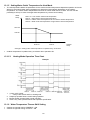
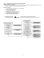
13.1.3 Total Running Current Control
1
2
3
When the monobloc unit running current exceeds X value, the compressor frequency will decrease.
If the monobloc unit running current does not exceed X value, the compressor frequency will return to normal
operating frequency.
If the monobloc unit running current continue to increase till exceed Y value, compressor will stop, and if this
occurs 3 times within 20 minutes, system will stop operation and OFF/ON remote control LED will blink (F16
error occurs).
09C
Operation Mode
Heating
X (A)
6.2
12C
Y (A)
10.6
X (A)
7.4
14C
Y (A)
10.6
X (A)
8.0
16C
Y (A)
10.6
X (A)
8.5
Y (A)
10.6
13.1.4 IPM (Power Transistor) Prevention Control
A. Overheating Prevention Control
1 When the IPM temperature rises to 95°C, compressor will stop immediately.
2 Compressor will restart delay 3 minutes when the IPM temperature decreases to 90°C.
If this condition repeats continuously 3 times within 30 minutes, system will stop operation and OFF/ON
remote control LED will blink (F22 error occurs).
B. DC Peak Current Control
1 When the current to IPM exceeds set value of 40.1 ± 5.0 A (MDF09C), 44.7 ± 5.0 A (MDF12C, MDF14C,
MDF16C), compressor will stop. Compressor will restart after three minutes.
2 If the set value exceeds again for more than 30 seconds after the compressor restarts, operation will restart
after two minutes.
3 If the set value exceeds again for within 30 seconds after the compressor restarts, operation will restart after
one minute. If this condition repeats continuously for seven times, system will stop operation and OFF/ON
remote control LED will blink (F23 error occurs).
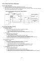
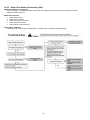
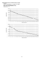
13.1.5 Compressor Overheating Prevention Control
The compressor operating frequency is regulated in accordance to compressor tank temperature as shown in
below figures. When the compressor tank temperature exceeds 112°C, compressor will stop, and if this occurs
4 times within 30 minutes, system will stop operation and OFF/ON remote control LED will blink (F20 error
occurs).
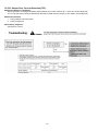
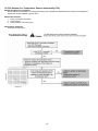
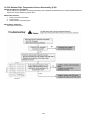
62
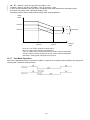
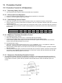
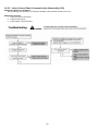
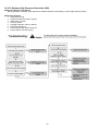
13.1.6 Low Frequency Protection Control 1
When the compressor continuously operates at frequency lower than 25 Hz for 240 minutes, the operation
frequency will change to 24 Hz for 2 minutes.
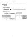
13.1.7 Low Frequency Protection Control 2
When all the below conditions comply, the compressor frequency will change to lower frequency.
Temperature, T, for:
Outlet water (°C)
Outdoor air (°C)
Indoor heat exchanger (°C)
Heating
T < 14 or T 48
T < 4 or T 24
T 0
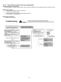
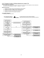
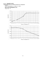
13.1.8 High Pressure Sensor Control
Purpose:
- To protect the system operation.
Detection period:
- After compressor on for 5 minutes.
Detection conditions:
- When abnormal high voltage detection, 5V or when open circuit detection 0V for 5 seconds continuously.
After detection:
- When abnormality is detected continue 5 seconds, unit stop operation.
- OFF/ON control panel LED will blink (H64 error occurs).
13.1.9 Outside Temperature Current Control
13.1.10 Crank Case Heater Control
Purpose:
- For compressor protection during low outdoor ambient operation (during heating low temperature operation).
Control content:
a. Trigger heater START condition
o when the outdoor air temperature is 4°C or below, and discharge temperature is 11.6°C or below.
b. Resetting heater STOP condition
1. when the outdoor air temperature exceeds entry condition (6°C)
2. when the discharge temperature exceeds entry condition (18.8°C)
13.2 Protection Control for Heating Operation
13.2.1 Outdoor Air Temperature Control
The maximum current value is regulated when the outdoor air temperature rises above 14°C in order to avoid
compressor overloading.
13.2.2 Deice Operation
When Monobloc unit (Refrigerant system) pipe temperature and outdoor air temperature is low, deice operation start
where monobloc unit fan motor stop.
63
14. Servicing Mode
14.1 Test Run
1
2
3
Fill up the boiler tank with water. For details refer to boiler tanks installation instruction and operation
instruction.
Set ON to the monobloc unit and RCCB. Then, for remote control operation please refers to monobloc unit
operation instruction.
For normal operation, pressure gauge reading should be in between 0.05 MPa and 0.2 MPa.
If necessary, adjust the water pump speed accordingly to obtain normal water pressure operating range. If
adjust water pump speed cannot solve the problem, contact your local authorized dealer.
14.2 Proper Pump Down Procedure
1
2
3
4
5
6
Make sure the OFF/ON remote control LED is OFF (no operation).
Press the “PUMPDW” switch on remote control to begin PUMP DOWN mode. Operate the system in PUMP
DOWN mode for 10 ~ 15 minutes.
After 10-15 minutes, (after 1 or 2 minutes in case very low ambient temperatures (< 10°C)), fully close 3 way
valve (Liquid side).
After 3 minutes, fully close 3 way valve (Gas Side).
Press the “OFF/ON” switch on remote control to stop PUMP DOWN mode.
Remove the refrigerant piping.
14.3 How to Adjust Water Flow Rate
Before adjust the water flow rate, make sure that the total water volume in the installation is 30 litres minimum
(09C3) and 50 litres minimum (12C6, 14C6 & 16C6).
The water flow rate can be adjusted with select the water pump speed on the water pump. The default setting is
moderate speed (II). Adjust it to high speed (III) and slow speed (I) if necessary (e.g. reduce the noise of running
water).
Below graph shown the external static pressure (kPa) versus water flow rate (l/min).
Flow rate characteristic of indoor unit is as per above mentioned.
14.4 Expansion Vessel Pre Pressure Checking
Expansion Vessel with 10L air capacity and initial pressure of 1 bar is installed in this monobloc unit.
Total amount of water in system should be below 200L.
(Note: This amount of water is not include the tank unit volume)
If total amount of water is over 200L, please add expansion vessel.
Please keep the installation height difference of system water circuit within 7m.
(Inner volume of same monobloc unit is about 5L)
64
15. Maintenance Guide
In order to ensure optimal performance of the unit, checks and inspections on the unit and the field wiring must be
carried out regularly. Please request a licensed technician for carry out maintenance job.
Before carried out any maintenance or repair work, and removing the front plate of heat exchanger unit, always
switch off all power supply (i.e. monobloc unit power supply, heater power supply and sanitary tank power supply).
Below checks must be carried out at least once a year.
1
2
3
4
Water pressure
Water pressure should not lower than 0.05 MPa (with inspects the pressure gauge). If necessary add tap
water into boiler tank. Refer to boiler tank installation instruction for details on how to add water.
Pressure relief valve
o Take out the cover with remove the mounting screw for access to the pressure relief valve.
o Check for correction operation of pressure relief valve by turn up the lever to become horizontal. (Refer
to figure below)
o If you do not hear a clacking sound (due to water drainage), contact your local authorized dealer.
o Turn down the lever after checking finish.
o In case the water keeps drained out from the unit, switch off the system, and then contact your local
authorized dealer.
o Reinstall the cover with tighten the mounting screws properly, if the pressure relief valve is functioning
normal.
Indoor unit control board area
Thorough visual inspection of the control board and look for defects, i.e. loose connection, melting of wire
insulator and etc.
RCCB
Ensure the RCCB set to “ON” condition before check RCCB.
Turn on the power supply to the monobloc unit.
This testing could only be done when power is supplied to the monobloc unit.
WARNING
Be careful not to touch parts other than RCCB test button when the power is supplied to Monobloc Unit. Else, electrical shock
may happen.
o
o
o
o
5
Push the “TEST” button on the RCCB. The lever would turn down and indicate “0” and indicate green
colour if it functions normal.
Contact authorized dealer if the RCCB malfunction.
Turn off the power supply to the monobloc unit.
If RCCB functions normal, set the lever to “ON” again after testing finish.
How to release the trapped air in water circuit
o Turn up the lever to become horizontal. (Refer to figure “Pressure relief valve”). The trapped air will be
drained out together with water. After few seconds, turn down the lever to stop the water drainage.
o Repeat it until the bubbling sound disappear.
65
6
Reset overload protector
Overload Protector serves the safety purpose to prevent the water over heating. When the Overload
Protector trip at high water temperature, take below steps to reset it.
a. Take out OLP Cover.
b. Use a test pen to push the centre button gently in order to reset the Overload protector.
c. After finish, install back the Overload protector following the reverse order of step a & b.
7
External water filter (field supply)
Clean the external water filter in regularly basic.
o External water filter is located inside the tube connector which is before water inlet connector of
monobloc unit (indicated with “WATER IN”). (Refer to figure below)
o Use spanner to detach the tube connector nut.
o Take out the filter carefully so that not deforms it shape.
o Use tap water only to wash the residue on the filter. If necessary, gently use soft brush only to clean the
hard dirt.
o After clean, put it back to the original location and tighten the nut connection with torque wrench.
66
16. Troubleshooting Guide
16.1 Refrigeration Cycle System
In order to diagnose malfunctions, make sure that there
are no electrical problems before inspecting the
refrigeration cycle. Such problems include insufficient
insulation, problem with the power source, malfunction of
a compressor and a fan.
The normal pressure of the refrigeration cycle depends
on various conditions, the standard values for them are
shown in the table on the right.
67
16.2
Relationship Between The Condition Of The Monobloc Unit And
Pressure And Electric Current
Heating Mode
Condition of the Monobloc Unit
Low Pressure
High Pressure
Electric current during operation
Water leakage or insufficient water flow
rate in the system
Excessive amount of refrigerant
Inefficient compression
Insufficient refrigerant
(gas leakage)
Monobloc unit (refrigerant system) heat
exchange deficiency
Clogged expansion valve or Strainer
Carry out the measurements of pressure, electric current, and temperature fifteen minutes after an operation is
started.
68
16.3 Breakdown Self Diagnosis Function
16.3.1 Self Diagnosis Function (Three Digits Alphanumeric Code)
When abnormality occur during operation, the system will stop operation, and OFF/ON remote control LED will
blink and error code will display on the remote control Timer display LCD.
Even error code is reset by turning OFF power supply or by pressing ERROR RESET button, if the system
abnormality is still un-repaired, system will again stop operation, and OFF/ON remote control LED will again blink.
The error code will store in IC memory.
To check the error code
1 When an abnormality occurs, system will stop operation and OFF/ON remote control LED will blink.
2 Error code of the abnormality will display on the remote control timer display LCD.
3 To determine the abnormality description, the Error Code table needs to be referred.
To display past/last error code
1 Turn ON power supply.
2 Press and hold the CHECK button for more than 5 seconds to enter status mode.
3 Press the SEARCH DOWN/UP button to retrieve past/last error code.
4 Press the CANCEL button or wait 30 seconds to exit status mode.
To permanently delete error code from IC memory
1 Turn ON power supply.
2 Press and hold the ERROR RESET button for more than 8 seconds till a beep sound is heard.
69
16.4 Error Codes Table
Diagnosis display
Abnormality / Protection control
Abnormality Judgement
H00
H12
No abnormality detected
Indoor/Outdoor capacity unmatched
—
90s after power supply
H15
Continue for 5 sec.
H42
Outdoor compressor temperature sensor
abnormality
Indoor refrigerant liquid temperature
sensor abnormality
Compressor low pressure abnormality
H62
H64
Water flow switch abnormality
Refrigerant high pressure abnormality
Continue for 1 min.
Continue for 5 sec.
H70
Back-up heater OLP abnormality
Continue for 60 sec.
H72
H76
Continue for 5 sec.
—
H90
Tank sensor abnormal
Indoor – remote control communication
abnormality
Indoor/outdoor abnormal communication
> 1 min after starting operation
H91
Tank heater OLP abnormality
Continue for 60 sec.
H95
H98
Indoor/Outdoor wrong connection
Outdoor high pressure overload
protection
—
—
H99
Indoor heat exchanger freeze prevention
—
F12
Pressure switch activate
F14
Outdoor compressor abnormal revolution
F15
Outdoor fan motor lock abnormality
F16
Total running current protection
F20
Outdoor compressor overheating
protection
F22
IPM (power transistor) overheating
protection
Outdoor Direct Current (DC) peak
detection
Refrigeration cycle abnormality
3 times occurrence within 30
minutes
7 times occurrence
continuously
2 times occurrence within 20
minutes
Cooling/Heating cycle changeover
abnormality
Pressure switch abnormality
Outdoor air temperature sensor
abnormality
Indoor water inlet temperature sensor
abnormality
Outdoor discharge pipe temperature
sensor abnormality
4 times occurrence within 30
minutes
Continue for 1 min.
Continue for 5 sec.
H23
F23
F24
F25
F27
F36
F37
F40
Continue for 5 sec.
—
4 times occurrence within 20
minutes
4 times occurrence within 20
minutes
2 times occurrence within 30
minutes
3 times occurrence within 20
minutes
4 times occurrence within 30
minutes
Continue for 5 sec.
Continue for 5 sec.
70
Primary location to verify
—
Indoor/outdoor connection wire
Indoor/outdoor PCB
Specification and combination table in
catalogue
Compressor temperature sensor
(defective or disconnected)
Refrigerant liquid temperature sensor
(defective or disconnected)
Outdoor pipe temperature sensor
Clogged expansion valve or strainer
Insufficient refrigerant
Outdoor PCB
Compressor
Water flow switch
Outdoor high pressure sensor
(defective or disconnected)
Back-up heater OLP
(Disconnection or activated)
Tank sensor
Indoor - control panel
(defective or disconnected)
Internal/external cable connections
Indoor/Outdoor PCB
Tank heater OLP
(Disconnection or activated)
Indoor/Outdoor supply voltage
Outdoor high pressure sensor
Water pump or water leakage
Clogged expansion valve or strainer
Excess refrigerant
Outdoor PCB
Indoor heat exchanger
Refrigerant shortage
Pressure switch
Outdoor compressor
Outdoor PCB
Outdoor fan motor
Excess refrigerant
Outdoor PCB
Compressor tank temperature sensor
Clogged expansion valve or strainer
Insufficient refrigerant
Outdoor PCB
Compressor
Improper heat exchange
IPM (Power transistor)
Outdoor PCB
Compressor
Insufficient refrigerant
Outdoor PCB
Compressor low compression
4-way valve
V-coil
Pressure switch
Outdoor air temperature sensor
(defective or disconnected)
Water inlet temperature sensor
(defective or disconnected)
Outdoor discharge pipe temperature
sensor (defective or disconnected)
Diagnosis display
Abnormality/Protection control
F41
PFC control
F42
Outdoor heat exchanger temperature
sensor abnormality
Outdoor defrost sensor abnormality
F43
F45
F46
F95
Indoor water outlet temperature sensor
abnormality
Outdoor Current Transformer open
circuit
Abnormality Judgement
4 times occurrence within 10
minutes
Continue for 5 sec.
Continue for 5 sec.
Continue for 5 sec.
—
Cooling high pressure overload
protection
—
71
Primary location to verify
Voltage at PFC
Outdoor heat exchanger temperature
sensor (defective or disconnected)
Outdoor defrost sensor (defective or
disconnected)
Water outlet temperature sensor
(defective or disconnected)
Insufficient refrigerant
Outdoor PCB
Compressor low
Outdoor high pressure sensor
Water pump or water leakage
Clogged expansion valve or strainer
Excess refrigerant
Outdoor PCB
16.5 Self-diagnosis Method
16.5.1 Connection Capability Rank Abnormality (H12)
Malfunction Decision Conditions:
During startup operation of cooling and heating, the capability rank of indoor checked by the outdoor is used to
determine connection capability rank abnormality.
Malfunction Caused:
1 Wrong model interconnected.
2 Wrong indoor unit or outdoor unit PCB (main) used.
3 Faulty indoor unit or outdoor unit PCB (main).
Abnormality Judgment:
Continue for 90 seconds.
72
16.5.2 Compressor Tank Temperature Sensor Abnormality (H15)
Malfunction Decision Conditions:
During startup and operation of cooling and heating, the temperatures detected by the compressor tank
temperature sensor are used to determine sensor error.
Malfunction Caused:
1 Faulty connector connection.
2 Faulty sensor.
3 Faulty outdoor unit PCB (main).
Abnormality Judgment:
Continue for 5 seconds.
73
16.5.3 Indoor Refrigerant Liquid Temperature Sensor Abnormality (H23)
Malfunction Decision Conditions:
During startup and operation of cooling and heating, the temperatures detected by the indoor refrigerant liquid
temperature sensor are used to determine sensor error.
Malfunction Caused:
1 Faulty connector connection.
2 Faulty sensor.
3 Faulty indoor unit PCB (main).
Abnormality Judgment:
Continue for 5 seconds.
74
16.5.4 Compressor Low Pressure Protection (H42)
Malfunction Decision Conditions:
During operation of heating and after 5 minutes compressor ON, when outdoor pipe temperature below -29°C or
above 26°C is detected by the outdoor pipe temperature sensor.
Malfunction Caused:
1 Dust accumulation on the outdoor unit heat exchanger.
2 Air short circuit at outdoor unit.
3 2 way valve partially closed.
4 Faulty outdoor unit fan motor.
5 Refrigerant shortage (refrigerant leakage).
6 Clogged expansion valve or strainer.
7 Faulty outdoor pipe temperature sensor.
8 Faulty outdoor unit main PCB (main).
75
16.5.5 Water Flow Switch Abnormality (H62)
Malfunction Decision Conditions:
During operation of cooling and heating, the water flow detected by the indoor water flow switch is used to
determine water flow error.
Malfunction Caused:
1 Faulty water pump.
2 Water leak in system.
3 Faulty connector connection.
4 Faulty water flow switch.
5 Faulty indoor unit PCB (main).
Abnormality Judgment:
Continue for 10 seconds (but no judgment for 9 minutes after compressor startup/restart).
76
16.5.6 Outdoor High Pressure Abnormality (H64)
Malfunction Decision Conditions:
During operation of cooling and heating, when the outdoor high pressure sensor output signal is 0Vdc or 5Vdc.
Malfunction Caused:
1 Faulty connector connection.
2 Faulty sensor.
3 Faulty outdoor unit PCB (main).
Abnormality Judgment:
Continue 4 times in 20 minutes.
77
16.5.7 Indoor Backup Heater OLP Abnormality (H70)
Malfunction Decision Conditions:
During operation of indoor backup heater, when no power supplies to indoor backup heater or OLP open circuit.
Malfunction Caused:
1 Faulty power supply connector connection.
2 Faulty connector connection.
3 Faulty indoor backup heater overload protector (OLP).
4 Faulty indoor unit PCB (main).
Abnormality Judgment:
Continue for 60 seconds.
78
16.5.8 Tank Temperature Sensor Abnormality (H72)
Malfunction Decision Conditions:
When tank connection is set to ON, the temperatures detected by the tank temperature sensor are used to
determine sensor error.
Malfunction Caused:
1 Faulty connector connection.
2 Faulty sensor.
3 Faulty indoor unit PCB (main).
Abnormality Judgment:
Continue for 5 seconds.
79
16.5.9 Indoor-Control Panel Communication Abnormality (H76)
Malfunction Decision Conditions:
During standby and operation of cooling and heating, indoor-remote control error occur.
Malfunction Caused:
1 Faulty connector connection.
2 Faulty remote contro.
3 Faulty indoor unit PCB (main).
80
16.5.10 Indoor/Outdoor Abnormal Communication (H90)
Malfunction Decision Conditions:
During operation of cooling and heating, the data received from outdoor unit in indoor unit signal transmission is
checked whether it is normal.
Malfunction Caused:
1 Faulty outdoor unit PCB (main).
2 Faulty indoor unit PCB (main).
3 Indoor-outdoor signal transmission error due to wrong wiring.
4 Indoor-outdoor signal transmission error due to breaking of wire in the connection wires between the indoor
and outdoor units.
5 Indoor-outdoor signal transmission error due to disturbed power supply waveform.
Abnormality Judgment:
Continue for 1 minute after operation.
81
16.5.11 Tank Booster Heater OLP Abnormality (H91)
Malfunction Decision Conditions:
During operation of tank booster heater, and tank booster heater OLP open circuit.
Malfunction Caused:
1 Faulty connector connection.
2 Faulty tank booster heater overload protector (OLP).
3 Faulty indoor unit PCB (main).
Abnormality Judgment:
Continue for 60 seconds.
82
16.5.12 Unspecified Voltage between Indoor and Outdoor (H95)
Malfunction Decision Conditions:
The supply power is detected for its requirement by the indoor/outdoor transmission.
Malfunction Caused:
1 Insufficient power supply.
2 Faulty outdoor unit PCB (noise filter/main).
83
16.5.13 Outdoor High Pressure Protection (H98)
Malfunction Decision Conditions:
During operation of heating, when pressure 4.0 MPa and above is detected by outdoor high pressure sensor.
Malfunction Caused:
1 Faulty water pump.
2 Insufficient water flow rate in system.
3 Water leak in system.
4 2/3 way closed.
5 Clogged expansion valve or strainer.
6 Excessive refrigerant.
7 Faulty outdoor high pressure sensor.
8 Faulty outdoor unit PCB (main).
84
16.5.14 Indoor Freeze-up Protection (H99)
Malfunction Decision Conditions:
During anti-freezing control in cooling operation, when the indoor refrigerant liquid temperature < 0°C.
Malfunction Caused:
1 Faulty water pump.
2 Insufficient water flow rate in system.
3 Water leak in system.
4 2 way valve partially closed.
5 Clogged expansion valve or strainer.
6 Refrigerant shortage (refrigerant leakage).
7 Faulty indoor refrigerant liquid temperature sensor.
8 Faulty indoor unit PCB (main).
85
16.5.15 Outdoor High Pressure Switch Activate (F12)
Malfunction Decision Conditions:
During operation of cooling and heating, when pressure 4.5MPa and above is detected by outdoor high pressure
switch.
Malfunction Caused:
1 Dust accumulation on the outdoor unit heat exchanger.
2 Air short circuit at outdoor unit.
3 Faulty water pump.
4 Insufficient water flow rate in system.
5 Water leak in system.
6 2/3 way valve closed.
7 Clogged expansion valve or strainer.
8 Excessive refrigerant.
9 Faulty outdoor high pressure sensor and switch.
10 Faulty outdoor unit PCB.
Abnormality Judgment:
Continue 4 times in 20 minutes.
86
16.5.16 Compressor Rotation Failure (F14)
Malfunction Decision Conditions:
A compressor rotation failure is detected by checking the compressor running condition through the position
detection circuit.
Malfunction Caused:
1 Compressor terminal disconnect.
2 Faulty outdoor unit PCB (main).
3 Faulty compressor.
Abnormality Judgment:
Continue 4 times in 20 minutes.
87
16.5.17 Outdoor Fan Motor (DC Motor) Mechanism Locked (F15)
Malfunction Decision Conditions:
The rotation speed detected by the Hall IC of the fan motor during fan motor operation is used to determine
abnormal fan motor (feedback of rotation > 2550rpm or < 50rpm).
Malfunction Caused:
1 Operation stop due to short circuit inside the fan motor winding.
2 Operation stop due to breaking of wire inside the fan motor.
3 Operation stop due to breaking of fan motor lead wires.
4 Operation stop due to fan motor Hall IC malfunction.
5 Operation error due to faulty outdoor unit PCB.
Abnormality Judgment:
Continue 2 times in 30 minutes.
88
16.5.18 Input Over Current Detection (F16)
Malfunction Decision Conditions:
During operation of cooling and heating, when outdoor current above 10.6A is detected by the current
transformer (CT) in the outdoor unit PCB.
Malfunction Caused:
1 Excessive refrigerant.
2 Faulty outdoor unit PCB (main).
Abnormality Judgment:
Continue 3 times in 20 minutes.
89
16.5.19 Compressor Overheating (F20)
Malfunction Decision Conditions:
During operation of cooling and heating, when temperature above 112°C is detected by the compressor tank
temperature sensor.
Malfunction Caused:
1 Faulty compressor tank temperature sensor.
2 2/3 way valve closed.
3 Refrigerant shortage (refrigerant leakage).
4 Clogged expansion valve or strainer.
5 Faulty outdoor unit PCB (main).
6 Faulty compressor.
Abnormality Judgment:
Continue 4 times in 30 minutes.
90
16.5.20 IPM Overheating (F22)
Malfunction Decision Conditions:
During operation of cooling and heating, when temperature 95°C is detected by the outdoor IPM temperature
sensor.
Malfunction Caused:
1 Faulty outdoor unit fan motor.
2 Faulty outdoor unit PCB (main).
Abnormality Judgment:
Continue 3 times in 30 minutes.
91
16.5.21 Output Over Current Detection (F23)
Malfunction Decision Conditions:
During operation of cooling and heating, when outdoor DC current is above 40.1 ± 5.0A (for: UD07~09CE) OR
44.7 ± 5.0A (for:UD12~16CE) is detected by the IPM DC Peak sensing circuitry in the outdoor unit PCB (main).
Malfunction Caused:
1 Faulty outdoor unit PCB (main).
2 Faulty compressor.
Abnormality Judgment:
Continue for 7 times.
92
16.5.22 Refrigeration Cycle Abnormality (F24)
Malfunction Decision Conditions:
1 During operation of cooling and heating, compressor frequency > Frated.
2 During operation of cooling and heating, running current: 0.65A < I < 1.65A.
3 During operation of cooling, water inlet temperature - indoor refrigerant liquid temperature < 5°C.
4 During operation of heating, indoor refrigerant liquid temperature - water inlet temperature < 5°C.
Malfunction Caused:
1 Faulty water inlet or indoor refrigerant liquid temperature sensors.
2 2/3 way valve closed.
3 Refrigerant shortage (refrigerant leakage).
4 Clogged expansion valve or strainer.
5 Faulty outdoor unit PCB (main).
6 Poor compression of compressor.
Abnormality Judgment:
Continue 2 times in 20 minutes.
93
16.5.23 Four Way Valve Abnormality (F25)
Malfunction Decision Conditions:
1 During heating operation, when the indoor pipe temperature of thermostat ON indoor unit < 0°C.
2 During cooling operation, when the indoor pipe temperature of thermostat ON indoor unit > 45°C.
Malfunction Caused:
1 Faulty sensor.
2 Faulty connector connection.
3 Faulty outdoor unit PCB (noise filter/main).
4 Faulty four way valve.
Abnormality Judgment:
Continue 4 times in 30 minutes.
94
16.5.24 Outdoor High Pressure Switch Abnormal (F27)
Malfunction Decision Conditions:
During compressor stop, and outdoor high pressure switch is remain opened.
Malfunction Caused:
1 Faulty connector connection.
2 Faulty switch.
3 Faulty outdoor unit PCB (main).
Abnormality Judgment:
Continue for 1 minute.
95
16.5.25 Outdoor Air Temperature Sensor Abnormality (F36)
Malfunction Decision Conditions:
During startup and operation of cooling and heating, the temperatures detected by the outdoor air temperature
sensor are used to determine sensor error.
Malfunction Caused:
1 Faulty connector connection.
2 Faulty sensor.
3 Faulty outdoor unit PCB (main).
Abnormality Judgment:
Continue for 5 seconds.
96
16.5.26 Indoor Water Inlet Temperature Sensor Abnormality (F37)
Malfunction Decision Conditions:
During startup and operation of cooling and heating, the temperatures detected by the indoor water inlet
temperature sensor are used to determine sensor error.
Malfunction Caused:
1 Faulty connector connection.
2 Faulty sensor.
3 Faulty indoor unit PCB (main).
Abnormality Judgment:
Continue for 5 seconds.
97
16.5.27 Outdoor Discharge Pipe Temperature Sensor Abnormality (F40)
Malfunction Decision Conditions:
During startup and operation of cooling and heating, the temperatures detected by the outdoor discharge pipe
temperature sensor are used to determine sensor error.
Malfunction Caused:
1 Faulty connector connection.
2 Faulty sensor.
3 Faulty outdoor unit PCB (main).
Abnormality Judgment:
Continue for 5 seconds.
98
16.5.28 Power Factor Correction (PFC) Abnormality (F41)
Malfunction Decision Conditions:
During operation of cooling and heating, when the PFC protection circuitry in the outdoor unit PCB (main) senses
abnormal high DC voltage level.
Malfunction Caused:
1 Power supply surge.
2 Compressor windings not uniform.
3 Faulty outdoor unit PCB (main).
Abnormality Judgment:
Continue 4 times in 10 minutes.
99
16.5.29 Outdoor Pipe Temperature Sensor Abnormality (F42)
Malfunction Decision Conditions:
During startup and operation of cooling and heating, the temperatures detected by the outdoor pipe temperature
sensor are used to determine sensor error.
Malfunction Caused:
1 Faulty connector connection.
2 Faulty sensor.
3 Faulty outdoor unit PCB (main).
Abnormality Judgment:
Continue for 5 seconds.
100
16.5.30 Outdoor Defrost Temperature Sensor Abnormality (F43)
Malfunction Decision Conditions:
During startup and operation of cooling and heating, the temperatures detected by the outdoor defrost
temperature sensor are used to determine sensor error.
Malfunction Caused:
1 Faulty connector connection.
2 Faulty sensor.
3 Faulty outdoor unit PCB (main).
Abnormality Judgment:
Continue for 5 seconds.
101
16.5.31 Indoor Water Outlet Temperature Sensor Abnormality (F45)
Malfunction Decision Conditions:
During startup and operation of cooling and heating, the temperatures detected by the indoor water outlet
temperature sensor are used to determine sensor errors.
Malfunction Caused:
1 Faulty connector connection.
2 Faulty sensor.
3 Faulty indoor unit PCB (main).
Abnormality Judgment:
Continue for 5 seconds.
102
16.5.32 Outdoor Current Transformer Open Circuit (F46)
Malfunction Decision Conditions:
A current transformer (CT) open circuit is detected by checking the compressor running frequency ( rated
frequency) and CT detected input current (< 0.65A) for continuously 20 seconds.
Malfunction Caused:
1 CT defective.
2 Faulty outdoor unit PCB.
3 Compressor defective (low compression).
Abnormality Judgment:
Continue 3 times in 20 seconds.
103
16.5.33 Cooling High Pressure Overload Protection (F95)
Malfunction Decision Conditions:
During operation of cooling, when pressure 4.0MPa and above is detected by outdoor high pressure sensor.
Malfunction Caused:
1 Dust accumulation in the outdoor unit heat exchanger.
2 Air short circuit at outdoor unit.
3 2 way valve closed.
4 Faulty outdoor unit fan motor.
5 Clogged expansion valve or strainer.
6 Excessive refrigerant.
7 Faulty outdoor high pressure sensor.
8 Faulty outdoor unit PCB (main).
104
17. Disassembly and Assembly Instructions
WARNING
High Voltage are generated in the electrical parts area by the capacitor. Ensure that the capacitor has discharged sufficiently before proceeding
with repair work. Failure to heed this caution may result in electric shocks.
WARNING
Be sure to switch off all the power supply before performing each of the below action.
17.1 To Remove The Cabinet Front Plate
17.2 To Remove The Cabinet Top Plate
105
17.3 To Remove The Cabinet Rear Plate
17.4 To Remove Pressure Gauge
To
Remove RCCB
17.5 To Remove RCCB
106
17.6 To Remove Transformer and Electronic Controller Board
17.7 To Remove Pressure Relief Valve
When reinstall the water pipe, use grease or water at the joining.
107
17.8 To Remove Flow Switch
When reinstall the water pipe, use grease or water at the joining.
17.9 To Remove Water Pump
When reinstall the water pipe, use grease or water at the joining.
17.10 To Remove Bottle Complete
When reinstall the water pipe, use grease or water at the joining
108
18. Technical Data
18.1 Operation Characteristics
18.1.1 WH-MDF09C3E8
Heating Characteristics at Different Outdoor Air Temperature
Condition
Outdoor air temperature : 7°C (DBT), 6°C (WBT)
Indoor water inlet temperature : 30°C
Indoor water outlet temperature : 35°C
Piping length : 7m
109
Heating Characteristics at Different Piping Length
Condition
Outdoor air temperature : 7°C (DBT), 6°C (WBT)
Indoor water inlet temperature : 30°C
Indoor water outlet temperature : 35°C
Piping length : 7m
110
18.1.2 WH-MDF12C9E8
Heating Characteristics at Different Outdoor Air Temperature
Condition
Outdoor air temperature : 7°C (DBT), 6°C (WBT)
Indoor water inlet temperature : 30°C
Indoor water outlet temperature : 35°C
Piping length : 7m
111
Heating Characteristics at Different Piping Length
Condition
Outdoor air temperature : 7°C (DBT), 6°C (WBT)
Indoor water inlet temperature : 30°C
Indoor water outlet temperature : 35°C
Piping length : 7m
112
18.1.3 WH-MDF14C9E8
Heating Characteristics at Different Outdoor Air Temperature
Condition
Outdoor air temperature : 7°C (DBT), 6°C (WBT)
Indoor water inlet temperature : 30°C
Indoor water outlet temperature : 35°C
Piping length : 7m
113
Heating Characteristics at Different Piping Length
Condition
Outdoor air temperature : 7°C (DBT), 6°C (WBT)
Indoor water inlet temperature : 30°C
Indoor water outlet temperature : 35°C
Piping length : 7m
114
18.1.4 WH-MDF16C9E8
Heating Characteristics at Different Outdoor Air Temperature
Condition
Outdoor air temperature : 7°C (DBT), 6°C (WBT)
Indoor water inlet temperature : 30°C
Indoor water outlet temperature : 35°C
Piping length : 7m
115
Heating Characteristics at Different Piping Length
Condition
Outdoor air temperature : 7°C (DBT), 6°C (WBT)
Indoor water inlet temperature : 30°C
Indoor water outlet temperature : 35°C
Piping length : 7m
116
18.2 Heating Capacity Table
18.2.1 WH-MDF09C3E8
Water Out
Outdoor Air
-15
-7
2
7
25
30
35
40
45
50
55
Input
Input
Input
Input
Input
Input
Capacity
Capacity
Capacity
Capacity
Capacity
Capacity
Power
Power
Power
Power
Power
Power
8650
3100
8300
3250
7950
3450
7600
3650
7150
3750
6700
3850
9350
2950
9000
3200
8850
3500
8700
3800
8300
3850
7900
3900
9310
2390
9000
2550
9000
2820
9000
3090
8900
3530
8800
3980
9000
1580
9000
1900
9000
2200
9000
2500
9000
2800
9000
3100
9000
1090
9000
1280
8730
1480
8460
1680
8280
1860
8100
2040
18.2.2 WH-MDF12C9E8
Water Out
Outdoor Air
-15
-7
2
7
25
30
35
40
45
50
Input
Input
Input Outdoor
Input
Capacity
Capacity
Capacity
Capacity
Capacity
Power
Power
Power
Air
Power
9300
3500
8900
3660
8500
3830
8100
3990
7500
4090
10400 3410 10000 3700
9600
3900
9200
4100
8700
4200
11800 3140 11400 3340 11000 3570 10600 3780
9800
3980
12000 2140 12000 2570 12000 3000 12000 3430 12000 3820
12000 1420 12000 1700 11800 1980 11700 2270 11500 2530
55
Input
Capacity
Power
7000
4200
8200
4310
9100
4180
12000 4200
11400 2780
30
55
Input
Capacity
Power
7300
4560
8500
4740
9500
4400
13300 5080
14000 3440
30
55
Input
Capacity
Power
7900
4950
9000
4990
9800
4550
14500 5450
15900 3930
18.2.3 WH-MDF14C9E8
Water Out
Outdoor Air
-15
-7
2
7
25
35
40
45
50
Input
Input
Input Outdoor
Input
Capacity
Capacity
Capacity
Capacity
Capacity
Power
Power
Power
Air
Power
9900
3910
9500
4050
9000
4190
8600
4330
7900
4450
11100 3730 10700 4000 10200 4200
9800
4400
9100
4570
12900 3510 12400 3730 11900 3950 11400 4170 10400 4290
14000 2600 14000 3110 14000 3630 14000 4140 13600 4610
14000 1750 14000 2100 14000 2450 14000 2800 14000 3050
18.2.4 WH-MDF16C9E8
Water Out
Outdoor Air
-15
-7
2
7
25
35
40
45
50
Input
Input
Input Outdoor
Input
Capacity
Capacity
Capacity
Capacity
Capacity
Power
Power
Power
Air
Power
10600 4130 10300 4420 10000 4710
9700
5000
8800
4980
11900 4070 11400 4300 10800 4500 10300 4700
9600
4850
13500 3780 13000 4000 12400 4220 11900 4440 10800 4500
16000 3250 16000 3780 16000 4310 16000 4840 15200 5150
16000 2350 16000 2730 16000 3110 16000 3490 16000 3710
18.3 Hydraulic Pump Performance
117
19. Exploded View and Replacement Parts List
19.1 WH-MDF09C3E5 WH-MDF12C6E5 WH-MDF14C6E5 WH-MDF16C6E5
(Refrigerant System)
118
119
Note:
The above exploded view is for the purpose of parts disassembly and replacement.
The non-numbered parts are not kept as standard service parts.
120
<Model: Refrigerant System>
REF.
DESCRIPTION & NAME
NO.
QTY. WH-MDF09C3E8 WH-MDF12C9E8 WH-MDF14C9E8 WH-MDF16C9E8 REMARKS
1
BASE PAN ASS’Y
1
CWD52K1251
←
←
←
2
COMPRESSOR
1
5JD420XBA22
←
←
←
3
BUSHING - COMPRESSOR MOUNT
3
CWH50055
←
←
←
4
NUT-COMPRESSOR MOUNT
3
CWH561049
←
←
←
4a
GASKET FOR TERMINAL COVER
3
CWB811017
←
←
←
5
CRANKCASE HEATER
1
CWA341053
←
←
←
6
CONDENSER COMPLETE
1
CWB32C3035
←
←
←
7
HIGH PRESSURE SENSOR
1
CWA50C2570
←
←
←
8
DISCHARGE MUFFLER
1
CWB121014
←
←
←
9
PRESSURE SWITCH
1
CWA101013
←
←
←
10
3-WAYS VALVE (GAS)
1
CWB011251
←
←
←
11
4-WAYS VALVE
1
CWB001046
←
←
←
12
3-WAYS VALVE(LIQUID)
1
CWB011292
←
←
←
13
STRAINER
1
CWB111032
←
←
←
20
SOUND PROOF MATERIAL
1
CWG302265
←
←
←
21
SOUND PROOF MATERIAL
1
CWG302266
←
←
←
22
SOUND PROOF BOARD
1
CWH15K1031
←
←
←
23
V-COIL COMPLETE - 4-WAY VALVE
1
CWA43C2169J
←
←
←
O
24
V-COIL COMPLETE - EXP.VALVE
1
CWA43C2385
←
←
←
O
25
SENSOR-OD TEMP/ COIL
1
CWA50C2730
←
←
←
26
SENSOR-COMP.DISCHARGE
1
CWA50C2576
←
←
←
←
O
27
SENSOR-COMP. TOP
1
CWA50C2629
←
←
27a
SENSOR-COMP.DEF
1
CWA50C2577
←
←
←
28
CABINET REAR PLATE-COMPLETE
1
CWE02K1019A
←
←
←
29
CONTROL BOARD CASING
1
CWH10K1133
←
←
←
31
TERMINAL BOARD ASS’Y
1
CWA28K1214
←
←
←
38
ELECTRONIC CONTROLLER (NOISE
FILTER)
1
CWA745822
←
←
←
O
O
44
ELECTRONIC CONTROLLER (MAIN)
1
CWA73C5078R
CWA73C5079R
CWA73C5080R
CWA73C5081R
46
REACTOR
1
G0C293J00001
←
←
←
48
TERMINAL COVER
1
CWH171039A
←
←
←
49
NUT-TERMINAL COVER
1
CWH7080300J
←
←
←
50
FAN MOTOR BRACKET
1
CWD54K1024
←
←
←
50a
SCREW-FAN MOTOR BRACKET
8
CWH551040J
←
←
←
53
FAN MOTOR (UPPER)
1
EHDS80AAC
←
←
←
O
54
FAN MOTOR (BOTTOM)
1
EHDS80BAC
←
←
←
O
54a
SCREW-FAN MOTOR MOUNT
8
CWH551016J
←
←
←
55
PROPELLER FAN ASSY
2
CWH00K1006
←
←
←
56
NUT-PROPELLER FAN
2
CWH561051
←
←
←
57
CABINET FRONT PLATE
1
CWE061098A
←
←
←
58
DISCHARGE GRILLE
2
CWE201073
←
←
←
59
CABINET SIDE PLATE ASSY
1
CWE04K1023A
←
←
←
60
WIRE NET
1
CWD041103A
←
←
←
61
CABINET TOP PLATE
1
CWE03C1105
←
←
←
62
ACCESSORY-COMPLETE
1
CWH82C1535
←
←
←
66
CABINET FRONT PLATE
1
CWE061274A
←
←
←
67
HANDLE
2
CWE161014
←
←
←
68
TUBE ASSY (CAP.TUBE)
1
CWT07K1541
←
←
←
70
EXPANSION VALVE
1
CWB051028
←
←
←
71
ELECTRO MAGNETIC SWITCH
1
K6C2AGA00002
←
←
←
72
ELECTRO MAGNETIC SWITCH
1
K6C4E8A00001
←
←
←
73
RECEIVER
1
CWB141055
←
←
←
74
REACTOR
3
G0C153J00009
←
←
←
121
REF.
DESCRIPTION & NAME
NO.
QTY. WH-MDF09C3E8 WH-MDF12C9E8 WH-MDF14C9E8 WH-MDF16C9E8 REMARKS
75
ACCESSORY CO.(DRAIN ELBOW)
1
CWG87C2030
←
←
←
76
PTC THERMISTOR
1
DADDG101001
←
←
←
Note:
All parts are supplied from PHAAM, Malaysia (Vendor Code: 00029488).
“O” marked parts are recommended to be kept in stock.
122
19.2 WH-MDF09C3E5 WH-MDF12C6E5 WH-MDF14C6E5 WH-MDF16C6E5
(Water System)
123
Note:
The above exploded view is for the purpose of parts disassembly and replacement.
The non-numbered parts are not kept as standard service parts.
124
<Model: Water System>
REF.
NO.
DESCRIPTION & NAME
QTY.
WHMDF09C3E8
WHMDF12C9E8
WHMDF14C9E8
WHMDF16C9E8
REMARKS
1
BASE PAN ASS’Y
1
CWD52K1242
←
←
←
2
HOT WATER COIL-COMPLETE
1
CWB90C1046
←
←
←
3
RECEIVER
1
CWB141039
←
←
←
4
FLOAT (FLOW SWITCH)
1
CWB601008
←
←
←
O
O
9
PUMP
1
CWB532096
←
←
←
16
BOTTLE COMP.
1
CWH90C0013
←
←
←
17
HEATER ASS'Y
1
CWA34K1029
CWA34K1030
←
←
O
O
18
SOUND PROOF MATERIAL
1
CWG302592
←
←
←
18a
SOUND PROOF MATERIAL
1
CWG302594
←
←
←
18b
SOUND PROOF MATERIAL
1
CWG302599
←
←
←
19
THERMOSTAT
4
CWA151065
←
←
←
O
20
ELECTRONIC CONTROLLER (MAIN)
1
CWA73C5088R
CWA73C5089R
CWA73C5090R
CWA73C5091R
O
21
TERMINAL BOARD ASS'Y
1
CWA28K1200
←
←
←
25
TERMINAL BOARD ASS'Y
1
CWA28K1211
←
←
←
26
TERMINAL BOARD ASS'Y
1
CWA28K1221
←
←
←
27
ELECTRO MAGNETIC SWITCH
1
K6C1AYY00004
←
←
←
28
TERMINAL BOARD ASS'Y
1
CWA28K1222
←
←
←
29
CIRCUIT BREAKER
1
CWA181005
←
←
←
O
30
TRANSFORMER-COMPLETE
1
CWA40C1075
←
←
←
O
31
SENSOR-COMPLETE
1
CWA50C2749
←
←
←
O
32
REMOTE CONTROL COMPLETE
1
CWA75C3687
←
←
←
O
33
PRESSURE GAUGE
1
CWB070001
←
←
←
O
34
PRESSURE RELIEF VALVE
1
CWB621011
←
←
←
O
39
OPERATING INSTRUCTION
1
CWF567865
←
←
←
40
INSTALLATION INSTRUCTION
1
CWF614632
←
←
←
42
TUBE CONNECTOR-COMPLETE
1
CWT29C1050
←
←
←
43
TUBE CONNECTOR-COMPLETE
1
CWT29C1055
←
←
←
44
CONTROL BOARD COVER
1
CWH131420A
←
←
←
45
HANDLE
2
CWE161014
←
←
←
46
CABINET SIDE PLATE ASS'Y
1
CWE04K1060A
←
←
←
47
CABINET FRONT PLATE
1
CWE061275A
←
←
←
48
CRANKCASE HEATER
1
CWA341071
←
←
←
49
CIRCUIT BREAKER
1
CWA181008
←
←
←
Note:
All parts are supplied from PHAAM, Malaysia (Vendor Code: 00029488).
“O” marked parts are recommended to be kept in stock.
[PHAAM] Printed in Malaysia
SYBZ1010-00
125