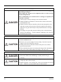
1
Service Manual PARAMAGNETIC OXYGEN ANALYZER TYPE: ZAJ TN512955b-E PREFACE This service manual contains information required for service engineers to perform maintenance and check of the paramagnetic oxygen analyzer. Since this manual does not provide basic description such as operating principle and key operation, you are requested to use this service manual together with related instruction manual. First read the instruction manual and the service manual carefully until an adequate understanding is acquired, and then proceed to installation, operation and maintenance of the gas analyzer. Wrong handling may cause an accident or injury. The specifications of this analyzer will be changed without prior notice for further product improvement. Modification of this gas analyzer is strictly prohibited unless a written approval is obtained from the manufacturer. Fuji Electric will not bear any responsibility for a trouble caused by such a modification. Delivered items Name Analyzer main frame Manufacturer: Type: Date of manufacture: Product nationality: Q'ty 1 Filter Restrictor Packing Packing Fuse Instruction manual 2 1 2 4 2 1 Test report 1 Wrench 2 Remarks Spare Spare Spare (filter area) Spare (for restrictor) 2A For reference gas joint Fuji Electric Co., Ltd. Described in Fuji Electric’s company nameplate on main frame Described in Fuji Electric's company nameplate on main frame Japan ©Fuji Electric Co., Ltd. 2001 Request Issued in Sep., 2001 Rev. 1st edition April, 2011 Rev. 2nd edition April, 2013 It is prohibited to transfer part or all of this manual without Fuji Electric’s permission in written format. Description in this manual will be changed without prior notice for further improvement. TN512955-E i CONTENTS PREFACE ..........................................................................................................................i CONTENTS ......................................................................................................................ii CAUTION ON SAFETY .................................................................................................iii 1. 2. NAME OF EACH PART...........................................................................................1 BEFORE MAINTENANCE ......................................................................................2 2-1. How to stop analyzer................................................................................................... 2 2-2. How to operate analyzer.............................................................................................. 2 2-3. How to pull out inner case........................................................................................... 2 3. ADJUSTMENT..........................................................................................................4 3-1. LCD contrast adjustment (Display 1: LCD at the top-front)....................................... 3 3-2. Output adjustment (4 to 20mA, 0 to 1V)..................................................................... 5 4. REPLACEMENT OF PARTS ...................................................................................6 4-1. 4-2. 4-3. 4-4. 5. Replacement of restrictor ............................................................................................ 6 Replacement of switching power supply..................................................................... 6 Replacement of sensor................................................................................................. 7 Replacement of display ............................................................................................... 8 CHECK FOR SIGNALS............................................................................................9 5-1. Check of voltage across printed circuit board ............................................................. 9 5-2. Check of magnet driven pulse ..................................................................................... 9 5-3. Check and adjustment of synchronous rectification waveforms ................................. 9 6. Countermeasures against trouble .............................................................................11 6-1. Error code and countermeasures ............................................................................... 11 6-2. Troubleshooting......................................................................................................... 13 7. Maintenance parts ....................................................................................................14 8. Others .......................................................................................................................15 Appendix .........................................................................................................................16 ii TN512955-E CAUTION ON SAFETY First of all, read this “Caution on safety” carefully, and then use the analyzer in the correct way. The cautionary descriptions listed here contain important information about safety, so they should always be observed. Those safety precautions are ranked in 2 levels; DANGER and CAUTION. DANGER Wrong handling may cause a dangerous situation, in which there is a risk of death or heavy injury. CAUTION Wrong handling may invite a dangerous situation, in which there is a possibility of medium-level trouble or slight injury or only physical damage is predictable. Caution on installation and transport of gas analyzer DANGER This unit is not explosion-proof type. Do not use it in a place with explosive gases to prevent explosion, fire or other serious accidents. This unit should be installed in a place which conforms to the conditions noted in the instruction manual. Otherwise, it may cause electric shocks, fire or malfunction of the unit. During installation work, care should be taken to keep the unit free from entry of cable chips or other foreign objects. Otherwise, it may cause fire, trouble or malfunction of the unit. CAUTION For lifting the gas analyzer, be sure to wear protective gloves. hands may invite an injury. Before transport, fix the casing so that it will not open. casing may be separated and fall to cause an injury. Bare Otherwise, the The gas analyzer is heavy. It should be transported carefully by two or more persons if manually required. Otherwise, body may be damaged or injured. TN512955-E iii Caution on piping In piping, the following precautions should be observed. Wrong piping may cause gas leakage. If the leaking gas contains a toxic component, there is a risk of serious accident being induced. Also, if combustible gas is contained, there is a danger of explosion, fire or the like occurring. Connect pipes correctly referring to the instruction manual. DANGER Exhaust should be led outdoors so that it will not remain in the locker and installation room. Exhaust from the analyzer should be relieved in the atmospheric air in order that an unnecessary pressure will not be applied to the analyzer. Otherwise, any pipe in the analyzer may be disconnected to cause gas leakage. For piping, use a pipe and a pressure reducing valve to which oil and grease are not adhering. If such a material is adhering, a fire or the like accident may be caused. Caution on wiring The unit must be earthed as specified. Otherwise, it may cause electric shocks, malfunction, etc. CAUTION Be sure to use a power supply of correct rating. Connection of power supply of incorrect rating may cause fire. Wiring work must be performed with the main power set to OFF to prevent electric shocks. Wires should be the proper one meeting the ratings of this instrument. If using a wire which cannot endure the ratings, a fire may occur. Caution on use DANGER CAUTION iv When handling the standard gas such as calibration gas, read the instruction manual of the standard gas carefully and use the gas correctly. Avoid continuous operation with the casing drawn out. casing may fall to cause an injury. Otherwise, the During operation, avoid opening the casing and touching the internal parts. Otherwise, you may suffer a burn or shock hazard. TN512955-E Caution on maintenance and check DANGER CAUTION Before working such as restrictor replacement with the casing open, be sure to turn off power supply, and perform air and N2 gas purging of not only the analyzer inside, but also the sample gas line and reference gas line. In addition, carefully prevent oil and grease from adhering to the restrictor, filter, packing, etc. Otherwise, poisoning, fire or explosion may be caused due to gas leakage, etc. Before working, take off a wrist watch, finger ring or the like metallic accessories. And never touch the instrument with a wet hand. Otherwise, you will have a shock hazard. If the fuse is blown, eliminate the cause, and then replace it with the one of the same capacity and type as before. Otherwise, shock hazard or fault may be caused. Others If the cause of any fault cannot be determined despite reference to the instruction manual, be sure to contact your dealer or Fuji Electric's technician in charge of adjustment. If the instrument is disassembled carelessly, you may have a shock hazard or injury. CAUTION Do not use a replacement part other than specified by the instrument maker. Otherwise, adequate performance will not be provided. Besides, an accident or fault may be caused. Replacement parts such as a maintenance part should be disposed of as incombustibles. TN512955-E v 1. NAME OF EACH PART 1 Handle OXYGEN GAS ANA POWER ON LYZER RANG O2 - vol% vol% 2 Knurled screw ESC MODE ENT 1 Handle OFF ZERO SPAN 2 Knurled screw 3 Power switch 4 Display and operation panel Front 8 Reference gas inlet 7 Purge gas inlet 6 Sample gas outlet 5 Sample gas inlet 12 Power terminal 9 I/O signal terminal 1 11 Screw for FG 10 I/O signal terminal 2 (option) 13 RS-232C connector (option) Rear TN512896-E 1 2. BEFORE MAINTENANCE 2-1. How to stop analyzer If sample gas includes flammable, corrosive, and toxic gases, purge the inner case by supplying a safe gas such as N2 or air from the cylinder, and then pull it out. To stop the gas, supply zero gas for a few minutes for protection of the sensor. First, stop the sample gas and then stop supplying the reference gas in 10 minutes. Turn OFF the power and disconnect the power cable except for LCD contrast adjustment given in Section 3-1, output adjustment in 3-2, and signal check in 5. 2-2. How to operate analyzer After sensor replacement, restrictor replacement or internal piping replacement has been completed, be sure to perform an airtightness test and flow check for reference gas according to “preparation for operation” in the instruction manual. Turn ON the power while supplying the reference gas to warm up the instrument. After replacement of a printed circuit board, sensor or switching power supply has been performed, carry out the signal check as described in Section 5. After that, perform zero calibration and span calibration and flow sample gas. (Caution) For protection of the sensor, be sure to flow reference gas first, and then sample gas. 2-3. How to pull out inner case Be sure to purge the cylinders and give protection to the sensor according to “How to stop analyzer” given in section 2-1. Turn the knurled screw on the front panel counterclockwise (as shown in Photo 2-1) and pull out the inner case by holding the handles with hands (refer to Photo 2-2.). In the inner case, the sensor, printed circuit boards and switching power supply are arranged. The sensor in the inner case is connected to the gas inlet of the outer case by Teflon tube. The printed circuit boards in the inner case are wired to output printed circuit boards of the outer case by cables. So, be careful when pulling out the inner case to avoid confusing the piping or wiring. Photo 2-1 Description of knurled screw Knurled screw Loosen the 2 knurled screws as shown in the Photo by turning them counterclockwise with a driver or fingers. 2 TN512955-E Photo 2-2 Inner case drawn Pull the handles toward you by holding them with hands. A stopper provided on the outer case prevents the inner case from being removed fully. Photo 2-3 Components inside the inner case SW power supply (1) (for magnet driving) SW power supply (2) (for circuit driving) Sensor A/D printed circuit board CPU printed circuit board Fuse TN512955-E Display printed circuit board 3 3. ADJUSTMENT 3-1. LCD contrast adjustment (Display 1: LCD at the top-front) The LCD of the concentration display is not provided with a means of performing contrast adjustment. The LCD contrast adjustment is performed by means of the VR of the display printed circuit board. When the VR is turned clockwise by a precision driver, display characters turn dark, and when it is turned counterclockwise, they turn light. Adjust the contrast to make it easy for the users to see the display. Photo 3-1 Contrast adjustment Contrast adjustment VR 4 TN512955-E 3-2. Output adjustment (4 to 20mA, 0 to 1V) To perform output adjustment, connect a digital voltmeter to the output terminal and set the measurement screen in the Factory Adjustment mode. Caution: Perform the output adjustment within the range of 4 to 2mA and 0 to 1V on the Adjustment screen. If other adjustment screen appears and you are at a loss what to do on the screen, press the ESC key several times to change it to the Measurement mode. In this case, don’t press the ENT key. Otherwise the adjustment contents would change, and disable adjustment. • Factory adjustment mode Press the MODE key several times on the Measurement screen, and the User Adjustment screen appears. Press the ZERO key 5 times on the User Adjustment screen, and the Factory Adjustment mode will be selected. This mode contains 4 to 20mA output, 0 to 1V output, coil pulse, manual gain, synchronous pulse, zero memory, span memory, magnet, reset, and peak code input. Be careful not to get in items other than “4 to 20mA output” and “0 to 1V output”. In 4 to 20mA output and 0 to 1V output, be sure to press the ENT key to save the change that is adjusted by (▲) or (▼) key. After adjustments, press the ESC key to escape to the Measurement mode. MEAS MODE H:ON R:OFF ESC ADJUST MODE ▲CLOCK ESC Factory Mode ▲4-20mA L:OFF A:OFF Press the MODE key several times to get in the Adjustment mode. >MOVE AVE Press the ZERO 0-1V ▼Sync period key 5 times. Move “4-20mA” or “0-1V” up one line by (▲) or (▼) key. ( > ) key to enter the Output Adjustment screen. 0-1V OUT ▼1V 0V ESC 0-1V OUT Press ▲▼ key Press the 0V ENT Select either 0V (zero) or 1V (span) and press the ( > ) key. ESC Adjust the output by (▲) or (▼) key while reading the digital voltmeter and press the ENT key. * Adjustment of 4 to 20mA should be performed in the same procedure as in 0 to 1V. TN512955-E 5 4. REPLACEMENT OF PARTS 4-1. Replacement of restrictor Stop the analyzer as described in section 2.1, “How to stop analyzer”. Then, pull out the inner case. The restrictor for reference gas line should be replaced when it is clogged (if gas flow is reduced to less than 5 mL.) Be careful when handling the restrictor to prevent it from being clogging with foreign matter since the restrictor diameter is very small. Never touch the restrictor directly. If the restrictor is dropped or touched in error, rinse it with acetone for about 10 seconds and mount it after drying. After restrictor replacement, apply soapy water to the connections of the pipe and joint and check for a gas leak. After confirming that there is no sign of a gas leak, check the gas flow to the restrictor (5 to 20 mL). Photo 4-1 Replacement of restrictor Illustration of disassembly Z A J Do not turn this wrench. Turn with wrench. Joint Packing Restrictor Packing Filter Cap screw Pipe 4-2. Replacement of switching power supply The switching power supply is classified into two types for magnet driving and for circuit use. As shown in the Photo 2-3, SW power supply (1) is used for magnet driving and SW power supply (2) for circuit use. To replace the switching power supply, perform “how to stop analyzer” given in section 2-1. Turn OFF this instrument power switch and disconnect the AC power cable. Then, pull the inner case out of the instrument as described in section 2-3, and remove the mounting board on which the switching power supply is mounted by loosening 2 screws from the top. Disconnect the primary and secondary connectors. Remove 4 screws and insulation washers fastening the mounting board and switching power supply to remove the switching power supply from the mounting board. When mounting a new switching power supply, reverse the removal procedure. Be sure to attach insulation screw washers required for mounting the new switching power supply on the mounting board. For replacement of switching power supply (1), check the magnet driving pulse (section 5-2), and for switching power supply (2), check voltage for the printed circuit board as shown in section 5-1. 6 TN512955-E 4-3. Replacement of sensor Caution: Since accuracy cannot be guaranteed when sensors are replaced at the site, sensors must be factory-adjusted at replacement. First, be sure to turn OFF the power switch to the instrument. Disconnect the AC power cable. Supply a zero gas and then pull out the inner case from the instrument, and detach cap nuts for pipes ① and ② which are connected to the sensor (as shown in Photo 4-2). Next, remove the SUS pipe for the reference gas in the same procedure as when the restrictor has been replaced. Remove thermistor (soldered) cable, magnet driving cable (screwed to the sensor lower part), and sensor signal cable (connector). Unscrew 3 screws from the mounting board while holding the sensor by hand and remove the sensor and mounting board from the instrument. Unscrew 4 screws fastening the mounting board so that the sensor can be separated from the mounting board. When mounting a new sensor, reverse the removal procedure. Before connecting the sensor signal cable, adjust voltage with VR1 until voltage specified on the replacement sensor is obtained from between CN 2 pins 1 and 4 on the A/D printed circuit board. After sensor voltage adjustment has been completed, connect the sensor signal cable and check the sensors against the operation check list. Photo 4-2 Sensor piping Pipe ① Pipe ② Photo 4-3 Photo 4-4 Inner case as viewed from upper part Inner case as viewed from lower part Magnet driving Sensor signal cable Thermistor cable TN512955-E 7 4-4. Replacement of display unit First, turn OFF the instrument power switch. Pull out the AC power cable. Draw the inner case from the instrument as described in section 2-3. Unscrew 6 screws from the side panel, 2 screws from the lower part of the inner case and remove the front frame from the inner case. Note that the soldered AC power cable cannot completely be removed from the instrument. Unscrew 6 screws fastening the display printed circuit board from the rear of the frame. Replace the display printed circuit board. After replacement, measure contrast of LCD according to section 3-1. Photo 4-5 Removal of front frame Screw Photo 4-6 Screw Removal of display printed circuit board. Screw 8 TN512955-E 5. CHECK FOR SIGNALS 5-1. Check of voltage across printed circuit board Check of power supply voltage CPU board J6 (GND) – J5 (+5V) ·············· +5.0 0.3V A/D board J13 (GND) – ··································· J11 (+15V) +15.0 0.5V J13 (GND) – ···································· J12 (-15V) -15.0 0.5V J13 (GND) – ···································· J14 (-12V) -12.0 0.5V J13 (GND) – ····································· J15 (+5V) +5.0 0.5V Output board CN1 11 pin (Vss) – CN1 - 10 (+5V) ························ +5.0 0.3V CN5 2 pin (VG) – CN5 - 1 (+15V) ······················ +15.0 0.5V CN5 2 pin (VG) – CN5 - 3 (-15V) ························ -15.0 0.5 5-2. Check of magnet driven pulse Check the pulse between terminals at the lower part of the sensor using an oscilloscope. 12.5or15Hz 30V 0V Pulse cycles depend on power frequencies: At power frequency of 50Hz, 12.5 0.5Hz At power frequency of 60Hz, 15.0 0.5 Hz 5-3. Check and adjustment of synchronous rectification waveforms Synchronous rectification waveforms should be checked if they vary widely. Check points Use an oscilloscope to check waveforms between pin 4 of AC amplifier board Q7 and A/D board J13. Note that the tester should be directly applied to the IC pin since pin 4 of the AC amplifier board Q7 is not provided with a check terminal. Be careful not to short between adjacent pins. Observe and check the waveforms according to waveform examples. TN512955-E 9 ・Good 2 0.5V 0V ・Not good 2 0.5V 0V Perform the following procedure when synchronous rectification waveforms are widely different from the good example. Caution: Failure to adjust synchronous rectification waveforms may result in inaccurate measurement. If you go into a wrong Adjustment Item screen of the Factory mode, be sure to press the ESC key, and then retry from the first step. On the different Adjustment Item screen, don’t press the “ENT” key or the > key, or accurate measurement cannot be performed and poor measurement results will be obtained. MEAS MODE H:ON R:OFF ESC ADJUST MODE ▲ CLOCK L:OFF A:OFF MODE Press the key several times to change to the Adjustment mode. >MOVE AVE ESC ZERO Factory Mode ▲Amp gain Sync phase ▼Zero save Press the key 5 times. In the Factory mode that is displayed, move Synchronous Pulse one line up by using ▲ or ▼ key. Press the ( > ) key to go into the Synchronous Pulse Phase adjustment screen. Sync-phase Press ▲▼ key ENT ESC 10 While observing the synchronous rectification waveforms with an oscilloscope, adjust them by using ▲ or ▼ key. Establish waveforms with the ENT key. If you want to stop halfway, press the ESC key. TN512955-E 6. Countermeasures against trouble 6-1. Error code and countermeasures Error code Error message Err1 AUTO ZERO CAL ERR Err2 AUTO SPAN CAL ERR Err3 INPUT OVER ERR Err4 INPUT UNDER ERR Err5 OUTPUT DEVICE ERR Cause Check and measures Calibration ・ Confirm the set zero or span calibration value is more value. than 20% FS ・ Confirm the gas concentration in gas different from cylinder. previous value. ・ Confirm the range. Sensor input value is abnormal. ・ Check if gas outside effective range is flowing. Output printed circuit board is abnormal. ・ Check if the connector of output printed circuit board is unplugged. ・ Replace the output printed circuit board. ・ Contact the nearest Fuji representative. Errl Auto zero calibration error (AUTO ZERO CAL ERR) This code is displayed if zero calibration values as measured in the automatic calibration fluctuate 20% larger than previous calibration value. If an error occurs, the instrument will be stopped without calibration. Countermeasures Perform zero point calibration manually. If an error does not occur with manual zero calibration, there is nothing wrong with the instrument. Check the settings for gas flowing time in the automatic calibration and the sampling system that is different between manual calibration and automatic calibration. If the MANUAL ZERO CAL ERR code appears in the manual calibration, check calibration gas, range settings, and calibration concentration settings. Caution) If the range settings have changed, an error may be displayed in an initial calibration. But, this is not an error. Perform zero-point calibration forcedly in the manual zero calibration. Err2 Auto span calibration error (AUTO SPAN CAL ERR) This code is displayed if span calibration value as measured in the automatic calibration fluctuates 20% larger than previous calibration value. If an error occurs, the instrument will be stopped without calibration. Countermeasures Perform span point calibration manually. If a span calibration error does not occur with manual span calibration, there is nothing wrong with the instrument. Check the settings for gas flow time in the span calibration and sampling system that is different between manual calibration and automatic calibration. If the MANUAL SPAN CAL ERR code is displayed in the manual calibration, check if calibration gas, range settings, and calibration concentration settings are proper. Caution) If the range setting has changed or when a gas cylinder for span calibration that is widely different from previous concentration value has been replaced, an error may occur in an initial calibration, but it there is nothing wrong with the instrument. Perform span-point calibration forcedly in the manual span calibration. TN512955-E 11 Err3 Input over error (INPUT OVER ERR) This code is displayed when the sensor signal is large. Countermeasures This error relates to reference gas, sample gas and range settings. First, check if the range settings are proper. Check if the reference gas is properly selected within the range to be set. (Starting from 0, N2 gas is If the reference gas is selected. From 21, air gas is selected, and from 100, O2 is selected.) correctly selected, check if there is possibility that any of the sample gases exceeds the range (oxygen is included too much). If the sample gas is beyond the range, change the range. Err 4 Input under error (INPUT UNDER ERR) This code is displayed when the sensor signal is larger in the negative direction. Countermeasures This error relates to reference gas, sample gas and range settings. Check for the range settings. Check if the reference gas is properly selected within the range to be set. (Starting from 0, N2 gas is selected. From 21, air gas is selected, and from 100, O2 is selected.) If it is properly selected, check if some gas among the sample gases is included as set in the range, or if even a small quantity of oxygen is contained in the reference gas, for example. If the sample gas is not included as set in the range, change the reference gas and range. Err 5 Output device error (OUTPUT DEVICE ERR) This code is displayed when a response is not received from an output printed circuit board. Countermeasures Check the cable between the CPU printed board and output printed board. Check if there is poor contact between the connector and receptacle or if the cable is disconnected. Manual zero calibration error (MANUAL ZERO CAL ERR) When zero calibration has been performed in the manual mode (via key operation), this code appears when calibrated values fluctuate 20% larger than previous calibrated values. Countermeasures Check that the range and calibration concentration settings are proper. Check the sampling system and calibration gas. Caution) If the range settings have changed, an error may be displayed in an initial calibration. But, this is not an error. Perform zero-point calibration forcedly in the manual zero calibration. Manual span calibration error (MANUAL SPAN CAL ERR) When span calibration has been performed in the manual mode (via key operation), this code appears when calibrated values fluctuate 20% larger than previous calibrated ones. Countermeasures Check that the range and calibration concentration settings are proper. Check the sampling system and calibration gas. Caution) If the range settings have changed, an error may be displayed in an initial calibration. But, this is not an error. Perform span-point calibration forcedly in the manual span calibration. 12 TN512955-E 6-2. Troubleshooting Indication fluctuates large. Is ambient vibration large? YES Take anti-vibration countermeasure. YES Include buffer tank in exhaust line. NO Is ambient noise large? NO By stopping measured gas Is it reduced? NO By stopping measured gas and reference gas Is it reduced? YES Does measurement gas pressure fluctuate? NO Reduce pressure fluctuation. For reference gas joint YES Is cap screw loose? YES NO NO Is reference gas line properly airtight? Is there any power noise? YES NO YES YES Tighten cap screw. Perform air-tightness check about reference gas line. Reduce noise. NO Is PC board abnormal? To external terminal] No output Replace PC board. YES NO Overhaul Is power supply supplied? NO Check power supply line. YES Replace fuse. NO Check measurement gas line. NO Check reference gas supply source. YES Is fuse burn out? NO Does measurement gas flow? YES Span adjustment cannot be made. Is reference gas pressure normal? YES Does reference gas flow? Needle valve for reduce valve NO YES YES To reference gas line] Zero adjustment cannot be made. Is air contained? Is valve fully open. YES NO Open needle valve fully. Replace restrictor and filter. Purge reference gas line. NO TN512955-E 13 7. Maintenance parts No. Name Man. Drawing No. Remarks Recommended replacement cycle 1 2 3 4 Restrictor Filter Packing Packing TK708941C1 TK708922P2 TK722676P4 TK722676P4 Reference gas joints Reference gas joints Near the filter For restrictor 2 years 2 years 2 years 2 years 5 Fuse 757642 2A, 6, 4 x 30 mm 2 years * Recommended replacement cycle for maintenance parts is at least 2 years. Prepare maintenance parts every 2 years. * Maintenance parts including No. 1 to No. 4 used near the reference gas should be replaced every 2 years. However, if there is no problem with reference gas flow (a constant flow of 5 to 20 mL is maintained) or indication (does not fluctuate), there is no need to replace them. 14 TN512955-E 8. Others If transmission function (RS232C) is available as an option, the following parameters can be viewed by a dedicated tool. Zero and span calibration coefficients Temperature table Span temperature compensation table Zero temperature compensation table 2% gain 100% gain Name Zero and span calibration coefficients Temperature table Span temperature compensation table Zero temperature compensation table 2% gain 100% gain : : : : : : Length of data Byte Number of data E00C6 8(8) 4 Word E011A 12 (C) 3 Long E00DA 36 (24) 9 Long E034E 12 (C) 3 Long E00C4 E00C5 1 (1) 1 (1) 1 1 Byte Byte First address * Length of data is expressed in bytes. TN512955-E A/D counted value at calibration Temperature table for temperature compensation Temperature compensation table for span point Temperature compensation table for zero point 2% O2 gain 100% O2 gain Type of data Figures in parenthesis are expressed in hexadecimal. 15 Appendix Appendix-1. Piping diagram Rear panel of analyzer 16 Inner case INLET ① OUTLET ② SUBGAS ④ Sensor ⑤ Gas inlet Gas outlet ③ No. Name of product Applicable length Piping diameter ① Teflon tube About 0.5 m 3 mm/2mm ② Teflon tube About 0.5 m 5 mm/4mm ③ SUS tube ④ Nylon tube About 0.5 m 3 mm/2mm ⑤ Teflon tube About 0.5 m 5 mm/4mm Reference gas inlet TN512955-E Power terminal block Noise filter TN512955-E Output board 2 A/D board AC amplifier Thermistor Thermistor Magnet terminal block Sensor 3-1 Output board 1 CPU board Flat cable Magnet driven wiring Appendix Flat cable Relay terminal block Appendix-3 Display board Fuse holder Power supply switch Appendix-2. Wiring diagram Printed circuit board CPU printed circuit board 17 Appendix 3-1 CPU printed board J5 J6 18 TN512955-E Appendix 3-2 A/D printed circuit board J11 J15 J13 J12 J14 TN512955-E 19 Appendix 3-3 Display output printed circuit board VR1 20 TN512955-E Appendix 3-4 Analyzer printed circuit board Appendix 3-5 Output printed circuit board CN1 TN512955-E CN5 21