1
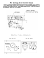
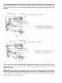
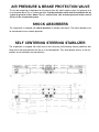
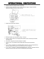
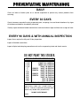
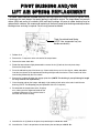
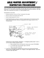
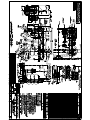
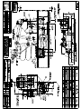
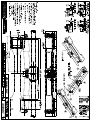
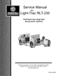
Service Manual
for
RSS-236 and RSS-236R
SURE-TRAC SELF STEER AIR RIDE
SUSPENSION SYSTEM
Revised 11/2003
Ridewell Corporation P.O. Box 4586 Springfield, MO 65808
800-641-4122 (417) 833-4565 Fax (417) 833-4560
www.ridewellcorp.comRidewell Corporation CONTENTS
Basic Operation...................................................................................................X
Air Control Panel.................................................................................................X
Operational Inspection........................................................................................X
Axle Caster Adjustment/Inspection.....................................................................X
Preventative Maintenance....................................................................................X
Basic Trouble Shooting.......................................................................................X
Bushing Replacement..........................................................................................X
Parts Illustration..................................................................................................X
SUSPENSION IDENTIFICATION: Ridewell Suspensions are identified by a metal tag welded to the left-hand
hanger that indicates part number, model number, capacity and date of manufacture. Consult your
vehicle manufacturer for your correct mounting height.
PARTS: For optimum suspension performance, order only Ridewell parts. Replacement parts for Model
RSS-236 are shown in Section 8 of this manual.
SALES, SERVICE & WARRANTY: If you need assistance regarding this product, please contact us and
we will be glad to help you.
Mailing Address
Ridewell Corporation
P.O. Box 4586
Springfield, MO 65808
Shipping Address
Ridewell Corporation
3715 E. Farm Rd. 94
Springfield, MO 65803
Phones, Fax, email
800-641-4122, (417) 833-4565
(417) 833-4560, fax
[email protected]
BASIC OPERATION
When properly maintained and operated within design limits, Ridewell's SURE-TRAC RSS-236
& RSS-236R self-steering suspension will provide many years of trouble-free service. It has several
features which make it easy to operate and will keep maintenance and downtime to an absolute
minimum.
1.) Extended life clamp-in urethane hanger pivot bushings for easy replacement.
2.) Optional automatic caster positioning for forward and reverse vehicle operation, with axle
down and loaded.
3.) Cab mounted controls for axle lift-load position.
4.) Self-contained shock absorbers that allow precise installation and insure proper shock and
air spring tolerances.
5.) Easy to install heavy-duty axle self-centering steering stabilizer.
Air Springs & Air Control Valve
This air ride suspension is designed to provide an auxiliary or "part-time" steerable axle for the vehicle.
The 4 air springs on this suspension work in conjunction to "lift" the axle off the ground when not in use
and provide "load" support when in use. The air control system controls the "lift" and "load" air springs
by controlling the volume of the air in the springs.
The air control system will also control the caster, if the axle of your suspension is a “reversing” type,
by automatic control through the vehicle back-up lighting systems, which actuates the reversing cylinder.
This means if the axle is in use under load, the caster will automatically switch to the direction of the vehicle travel.
The air control system for a “non-reversing” suspension (meaning the caster is fixed for a vehicle forward operation only with the axle down and loaded) will automatically raise the axle as the vehicle is
shifted into reverse.
IMPORTANT! It is recommended the suspension be allowed 5-10 seconds to activate prior to forward
and reverse operation. If either suspension system fails to activate, the vehicle operator may put the axle
in the up position or cease operations and inspect for the cause of failure. This will avoid causing possible damage to the suspension or axle.
AIR PRESSURE & BRAKE PROTECTION VALVE
The air ride suspension is dependent on air pressure from the vehicle supply system. Air pressure must
be maintained above 70 p.s.i. before operation. A brake protection valve must be installed in the air
system to prevent air loss below 70 p.s.i. and to insure safe air brake pressure in the event of
air loss in the suspension system.
SHOCK ABSORBERS
The suspension is equipped with shock absorbers to dampen road inputs. The shock absorber must
be maintained to insure smooth operation.
SELF CENTERING STEERING STABILIZER
The suspension is equipped with either one or two heavy-duty self-centering steering stabilizers that
keep the tie rod centered while the axle is in the lifted position. They also dampen shimmy in the suspension as transmitted by the road and tires.
OPERATIONAL INSPECTION
1. Inspect all fasteners at hanger to frame connection.
2. Inspect for proper installation of cross members between hangers. Hangers should be
adequately supported to prevent side movement.
3. Inspect axle to lower beam fasteners.
4. Build and maintain truck air pressure to 80 p.s.i. minimum.
5. Inspect air springs. Make sure all springs inflate and do not leak. Leaks may be checked
with soapy water.
6. Check all air connections for leaks and tighten if needed.
7. Inspect air lines. They should be free of sharp edge contact to prevent premature
failure.
8. If your vehicle is equipped with a reversing caster suspension, check reversing feature by
alternately shifting from forward to reverse with the axle in the lift position.
9. If your vehicle is equipped with non-reversing fixed caster suspension, alternately shift from
forward to reverse to make sure the axle will automatically raise and lower.
PREVENTATIVE MAINTENANCE
DAILY
Check for loose or broken parts on or around suspension to prevent any serious problems from
occurring.
EVERY 30 DAYS
Check clearances around all moving suspension parts, air springs, tires and shock absorbers. Any signs
of interference should be immediately corrected.
Visually inspect axle beam bolted connection to make sure bolts are tight and there are no signs of wear.
EVERY 90 DAYS & WITH ANNUAL INSPECTION
Inspect items required in daily and 30-day inspections.
Inspect all welded connections.
Inspect all pivot and clamping connections such as the suspension pivots and shock mounts.
DO NOT PAINT THIS STICKER
RIDEWELL SUSPENSION TORQUE CHART
BOLT SIZE
LUBRICATED THREADS
1 1/2”
1,100 FT. LB. (1,490
1 1/4”
1,000 FT. LB. (1,350
1 1/8”
500 FT. LB. (680
1”
GRADE 5
360 FT. LB. (490
1”
GRADE 8
460 FT. LB. (625
7/8”
350 FT. LB. (475
3/4”
GRADE 5
160 FT. LB. (220
3/4”
GRADE 8
190 FT. LB. (260
5/8”
100 FT. LB. (135
*3/4”
50 FT. LB. (70
*1/2”
25 FT. LB. (35
* AIR SPRING CONNECTION ONLY
N·m)
N·m)
N·m)
N·m)
N·m)
N·m)
N·m)
N·m)
N·m)
N·m)
N·m)
After suspension has been in operation for
approximately 6,000 miles (10,000 KLMS), all
fasteners must be re-tightened to specified torque.
Repeat every 50,000 miles (80,000 KLMS).
DO NOT OVER TORQUE!
990301
PIVOT B U S H I N G A N D / O R
L I F T AIR S P R I N G R E P L A C E M E N T
The SURE-TRAC RSS-236 and RSS-236R self-steering suspensions feature an easy to replace clampin bushing at the main hanger. No special tooling is required for service. The torque beam has press-in
rubber (2002 and earlier) or urethane (2002 and later) bushings. All press-in rubber bushings may be
replaced with urethane. We recommend replacing all urethane hanger pivot bushings and torque beam
bushings when servicing is required. Service may proceed as follows:
Triple Convoluted Load Spring
(NOTE: Your suspension may use
double convoluted.)
1. Deflate all air springs.
2. Remove the 1” cap screw at the axle end of the torque beam.
3. Remove the lower shock bolt.
4. Rotate the torque beam slightly downward to remove the six (6) bolts at the main pivot clamp.
Remove the torque beam.
5. Press the old bushing out of the beam eye. Clean inside the eye so it is free of glue, rubber and debris.
Coat the inner sleeve of the replacement bushing with light coat of anti-seize. Press in each half of the
new bushing followed by the inner sleeve.
6. Remove the urethane bushing from hanger pivot tube. (NOTE: The bushing is pre-split along its length
for easy removal and replacement.)
7. Clean the pivot tube on the hanger and apply a light coating of anti-seize to the tube. Install the new
bushing. (NOTE: The lift spring may be replaced at this time if required.)
8. Re-assemble the torque beam to the lift spring
arm, making sure the alignment knobs on the
urethane bushing are in line with the holes in
the beam and lift arm housing.
9. Assemble the six (6) bolts to the pivot clamp and torque to 120 ft. lbs. each.
10.
Assemble the 1” bolt in torque beam to lower beam pivot and torque to 460 ft. lbs.
OPERATING INSTRUCTIONS AIR CONTROL PANEL
UNDERSTANDING THE CONTROL PANEL
The control panel is equipped with one (1) adjustable pressure regulator, one (1) air gauge, and one (1)
flip switch or push/pull knob. The pressure regulator is labeled “Axle Load” and is used to adjust the
pressure in the load air spring. The flip switch or push/pull knob is labeled “Up/Down” and is used to
raise or lower the axle. The air gauge displays the air pressure in the load air spring only.
TO LIFT AXLE
Move the flip switch lever to the “Up” position or pull the knob out to raise the tires from the ground. This
will exhaust air from the load springs and fill the lift springs.
TO LOAD AXLE
Move the flip switch lever to the “Down” position or push the knob in to lower tires to the ground. This
will exhaust air from the lift springs and fill the load springs. Slowly turn pressure regulator labeled “Axle
Load” clockwise while noting the pressure reading on the air gauge. As air pressure increases, the load
applied to the auxiliary axle will increase. For the desired axle load distribution, correlate scaled axle
weights to the reading on the air pressure gauge. CAUTION: Do not operate suspension in “down”
position with less than 30 p.s.i. shown on gauge.
TRACTION CONTROL
Turn pressure regulator labeled “Axle Load” counterclockwise to reduce air pressure (load). This will
transfer load to the driving axle(s). Turn the regulator only until the desired traction is obtained.
CAUTION: Do not overload drive axle(s).
SUSPENSION PERFORMANCE
For trouble-free operation, follow instructions and perform maintenance as outlined on installation
drawings.
AXLE C A S T E R A D J U S T M E N T /
INSPECTION PROCEDURE
Your Ridewell SURE-TRAC RSS-236 and RSS-236R suspension offers an adjustable caster torque rod
feature, which can easily adjust to the proper axle caster angle that will give you optimum suspension
performance. The caster angle should be checked and/or adjusted during annual inspection, after major
repairs, after re-bushing the main pivots, or if “tracking” problems occur.
PROCEDURE AS FOLLOWS:
1. Build and maintain a minimum of 80 p.s.i air pressure in the system.
2. With the vehicle on level ground, lower the axle.
3. Adjust load spring pressure to 30 p.s.i.
4. Check forward caster by placing an inclinometer (angle gauge) on the load spring mounting
plate or other machined axle surface that is perpendicular to the king pin center line. See
illustration below:
Forward caster angle should be set between 3 - 5 1/2 degrees positive caster. If caster is
not in this range, see Basic Operation section.
a.
Loosen adjustable torque rod clamp bolts (reference part number 5037482B000).
b.
Turn threaded torque rod until proper angle is achieved.
c.
Tighten clamp bolts to 60 ft. lbs.
5. If you have a reversing caster suspension, shift vehicle to reverse and read inclinometer.
Reverse caster should be between 3 1/2 - 5 degrees in the negative direction. If adjustment
is required, repeat steps above.
BASIC T R O U B L E S H O O T I N G
MODEL RSS-236 (FIXED CASTER)
NOTE: Do not check system until minimum 80 p.s.i. air pressure is built and maintained.
1. Tracking Improperly - Check the following:
a.
Caster angle
b.
Excessive bushing wear
c.
Axle mounting bolts
d.
Load spring air pressure
e.
Steering stabilizer(s)
f.
Hanger alignment
2. Axle Fails to Lift - Check the following:
a.
Air system and lift springs
b.
Solenoid and electrical
c.
Improper assembly of torque beam after servicing
3. Tie Rod Not Centering in Lift Position - Check the following:
a.
Steering stabilizer(s)
MODEL RSS-236R (REVERSING CASTER)
NOTE: Do not check system until minimum 80 p.s.i. air pressure us built and maintained.
1. Tracking Improperly - Check the following:
a.
Caster angle
b.
Excessive bushing wear
c.
Axle mounting bolts
d.
Load spring air pressure
e.
Steering stabilizer(s)
f.
Hanger alignment
g.
Reversing cylinder and lever
h.
Solenoid and electrical
i.
Air system (supply)
2. Axle Fails to Lift - Check the following:
a.
Air system and lift springs
b.
Solenoid and electrical
c.
Improper assembly of torque beam after servicing
3. Tie Rod Not Centering in Lift Position - Check the following:
a.
Steering stabilizer(s)
b.
Solenoid and electrical
c.
Air system (supply)
PARTS I L L U S T R A T I O N S