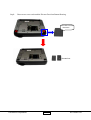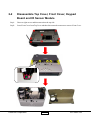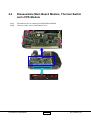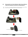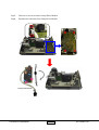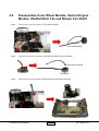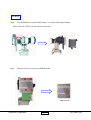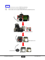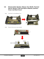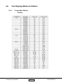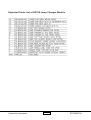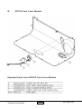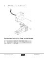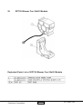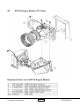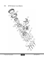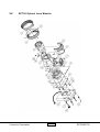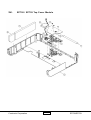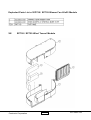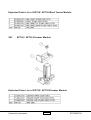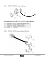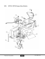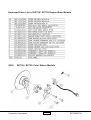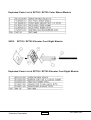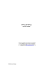
1
SERVICE MANUAL
Model Name : EP758/EP759
Prepared by SI :
________________________________________
Prepared by TSE :
________________________________________
Check by :
________________________________________
Approved by :
________________________________________
Date
Revise Version
Description
2004/10/12
V1.0
Initial Issue
2004/10/22
V1.1
Revise 7-2, 7-4, 7-6, 7-16, 7-17 and 7-32
Copyright October, 2004 . All Rights Reserved
Document #896-G04-01A . P/N: 36.89601.001
Preface
This manual is prepared for the maintenance service for EP758/EP759 Micro-portable XGA DLP
Projector. Maintenance procedures described in this manual are intended to isolate faulty parts and replace
them in the field. It also aims to serve as a guide in procuring replacement parts for this product.
This manual is copyrighted and all rights are reserved. This product may not, in whole or in part, be
copied, photocopied, translated or reduced to any electronic or machine readable form without prior written
consent except for copies retained by the purchaser for backup purpose.
This manual includes system overview, major system assembly, components’ description, and the
“Troubleshooting” making explanations on how to detect errors. It also includes a flow chart for checking or
correcting faults.
No warranty or representation, either expressed or implied, is made with respect to this
documentation, its quality, performance, merchantability or fitness for particular purpose.
No event that the vendor will be liable for direct, indirect, special, incidental or consequential damages arising out of the user or inability to use this product or documentation.
Notice:
The information found in this manual is subject to change without prior notice. Any subsequent
changes made to the data herein will be incorporated in further edition.
EP758/EP759 Service Manual
Copyright July, 2004
All Rights Reserved
Manual Version 1.0
Document #896-G04-01A
i
EP758/EP759
Table of Contents
Chapter 1
Chapter 2
Chapter 3
Chapter 4
Chapter 5
Introduction
1-1
Product Highlight
Optical Specification
Electrical Specification
Mechanical Specification
Environment
Compatible Modes
1-1
1-2
1-3
1-5
1-5
1-6
Disassembly of Procedure
2-1
Disassemble Lamp Module and Elevator Foot
Disassemble Top Cover, Front Cover, Keypad Board and
IR Sensor Module
Disassemble Main Board Module, Thermal Switch and LVPS Module
Disassemble Fan Guider Module, Wind Tunnel Module, Lamp Driver
Module and Axial Fan 90*25
Disassemble Color Wheel Module, Optical Engine Module, 45*45*9
Dish Fan and Blower Fan 60*25
Disassemble Speaker, Blower Fan 50*20, Thermal Sensor Board,
Interrupt Switch Module, Bottom Cover and Rear Cover
2-1
2-3
2-6
2-9
2-12
2-16
Troubleshooting
3-1
Equipment Needed
Main Procedure
3-1
3-2
Function Test and Alignment Procedure
4-1
Product
Test Equipment
Test Condition
Test Display Modes and Pattern
Inspection Procedure
4-1
4-1
4-1
4-2
4-7
Firmware Upgrade Procedure
5-1
Equipment Needed
Hardware Setup Procedure
Firmware Program Installation Procedure
5-1
5-1
5-2
ii
EP758/EP759
Chapter 6
DDC Key-in Procedure
6-1
Equipment Needed
Setup Procedure
DDC Key in Procedure
6-1
6-2
6-3
Appendix A
7-1
Exploded Overview
7-1
Appendix B
7-37
Serial Number System Definition
Reader’s Response
7-37
7-38
iii
EP758/EP759
Chapter 1
Introduction
This manual is applied to 0.7”*1 DMD Color Projector with digital imaging functionality based on Digital
Micromirror Device (DMD) technology. It’s the mode of single panel, 250watt(EP758) / 300 watt(EP759)
long life lamp.
The manual gives you a brief description of basic technical information to help in service and main taining
the product.
Your customers will appreciate the quick response time when you immediately identify problems that occur
with our products. We expect your customers will appreciate the service that you offer them.
This manual is for technicians and people who have an electronic background. Send the product back to the
distributor for repairing and do not attempt to do anything that is complex or is not mentioned in the
troubleshooting.
1-1
Product Highlights
-
One 0.7" DDR DMD projection system with 2000(EP758) / 2210(EP759) ANSI lumen
-
Contrast (FOFO) : 1000 : 1
-
250(EP758) / 300(EP759) - Watt Lamp 1500hrs (user replaceable)
-
High efficiency cooling system with system acoustic noise level 33dBA(EP758) / 36dBA
(EP759) ( Average )
-
Dimensions : 250*335*100mm w/wind tunnel
-
NTSC/PAL/SECAM video capability with S-video / composite / component, and HDTV
(480i/p, 576i/p, 720p, 1080i)
-
Auto detection of computer signal input.
-
Auto Image.(Auto-tracking /frequency /position adjustment)
-
Automatically saves adjustments for future use
-
On-screen menu with 11 languages(EP758) / 9 languages(EP759)
-
One DVI input ( Including Analog and Digital RGB signal ) with HDCP function
-
Wireless remote controller
Coretronic Corporation
1-1
EP758/EP759
1-2
Optical Specification
Technology
Single 0.7” XGA DDR DMD chip
Resolution
1024 x 768
Brightness
Specification: 2500(EP758) / 3000(EP759) lumens
Typical output: 2000(EP758) / 2600(EP759) lumens
Contrast ratio
Specification: 1500:1 full on/full off
Typical output: 1300:1
Minimum: 1000:1 full on/full off
Uniformity
Specification: 85% (JBMA)
Displayable colors
16.7 million colors 256 shades of gray
Color temperature
7500oK adjustable form 6500oK - 9500oK
Lamp type
300 watt lamp and power-saving mode to 250 watts for EP759
250 watt lamp and power-saving mode to 200 watts for EP758
Lamp life
2000 hours full on mode
1500 hours to 50% survival typical full on mode
3000 hours in ECO-mode
2500 hours to 50% survival typical in econo-mode
Projection lens
F/2.2-2.6; f24.5 –29.4: 1.2x (EP759)
F/2.4-2.6; f28-33.6:1.2x (EP758)
Projection screen size
Adjustable from 24.4” to 292.5” (EP759)
Adjustable from 24.6” to 246” (EP758)
Projection distance
1.2-10m
Coretronic Corporation
1-2
EP758/EP759
1-3 Electrical specification
Input connections
- Terminal:DVI x 1 (Analog RBG, Component, HDTV, Digital RGB, HDCP)
15 pins D-sub VGA signal input
Composite Video X 1.
Three RCA connectors for Component video/HDTV input
Audio Input X 1
USB X 1 (for remote mouse)
S-Video X 1
IR x 2 (Front, Top panel)
RS232 Serial Control x 1 (3 pin mini din)
Power Cord x 1
- PC/Video: One DVI-I + USB(analog and digital YCbCr/YPbPr w/ HDCP).
- One D-Sub 15-pin connector for analog RGB/component video/HDTV
- Video:
- Control:
3-RCA type connector for YPbPr component video.
One mini DIN for S-video connector.
One composite RCA type connector.
1 RS-232 (use standard Mini Dim 3 pins configuration) (with talk back ability and 9600
baud rate, talk back ability must include lamp hours) (on/off and all inputs should have
discreet IR and RS-232 commands)
One Audio input for every input- (Phone Jack, Stereo)
Outputs
One 15pin D-Sub Output
One audio out
Audio
Two watt built in two speakers respectively
Lock
One Kensington key lock hole
Tilt angle
7 degrees with elevator mechanism
Coretronic Corporation
1-3
EP758/EP759
IR receivers
Front and Top of projector
Power Switch
No toggle power switch required or wanted
Power supply
Universal AC 100-240V 50/60 Hz with PFC input
Used OSRAM P-VIP 300/1.3 E21.8 300W Lamp (EP759)
Used Phillip E21.8 250W Lamp (EP758)
Power consumption
Standby mode - < 10 Watt @ 110V AC
Operational noise
36 dB(A) 300W(EP759) Normal mode
33 dB(A) 250 W(EP758) Normal mode
Input signal spec.
Hsync Frequency 15 ~ 100 kHz
Vsync Frequency 43 ~ 120 Hz
Video Signal RGB (PC)
-Analog RGB 0.7Vp-p, 75 ohm, Separate TTL H,V Sync.
-Analog RGB 1Vp-p, 75 ohm, Sync. On Green signal
-Analog RGB 0.7Vp-p, 75 ohm, Composite TTL Sync.
Video
-Composite video 1Vp-p,75 ohm
-S-video Luminance 0.714Vp-p,75 ohm
-Chrominance 0.286Vp-p,75 ohm
Computer Compatibility (Analog/Digital)
System Controller
Video Compatibility
PIXELWORKS PW463
Standards
-NTSC
-PAL
-SECAM
-HDTV
Horizontal scan rate
15 – 100 kHz
Vertical scan rate
43 – 120 Hz
Coretronic Corporation
- M (3.58 MHz), 4.43 MHz
- B, D, G, H, I, M, N
- B, D, G, K, K1, L
- 480i/576i ; 480p/576p ; 720p ; 1080i
1-4
EP758/EP759
1-4 Mechanical Specification
Weight
Approximate 8lbs
Unit dimension (W X D X H)
inner dimension 335*250*100 (mm)
Cooling System
Advanced air flow
Three(EP758) / Four(EP759) fans with low system acoustic noise level
Temperature control circuits with adaptive voltage
control fan speed
Tilt Angle
7 degrees with elevator mechanism
Keystone correction
± 16° Vertical and Horizontal
Lamp Door Protection
Lamp power supply shut off automatically when door open
1-5 Environment
Temperature
Operating:
Storage:
5 — 35°C
-20 — 60°C
Maximum Humidity
Operating:
Storage:
5 — 35°C, 80% non-condensing
-20 — 60°C, 80% non-condensing
Acoustic noise level
EP758
/EP759
33dB(A)
/ 36dB(A) ( Typical, 23 ± 2°C) with wind tunnel design
33dB(A) 250W / 36 dB(A) 300W lamp mode.
30dB(A) 200W / 33 dB(A) 240 W dimmable mode.
Follow ISO-7779 regulation sound pressure level A weighting measurement
Coretronic Corporation
1-5
EP758/EP759
Lamp life
1500 hours typical, 50% survival rate
Altitude
Operating 0~2,500 ft
2,500~5,000 ft
5,000~10,000 ft
Storage
40,000 ft (Max)
MTBF
12000 HRs
5°C~35°C
5°C~30°C
5°C~25°C
1-6 Compatible Modes
Analog
Compatibility
VGA
SVGA
XGA
SXGA
SXGA+
UXGA
MAC LC 13”
MAC II 13”
MAC 16”
MAC 19”
MAC
MAC G4
MAC G4
MAC G4
i Mac DV
i Mac DV
i Mac DV
Coretronic Corporation
Resolution
640x350
640x350
640x400
640x480
640x480
640x480
640x480
720x400
720x400
800x600
800x600
800x600
800x600
800x600
1024x768
1024x768
1024x768
1024x768
1024x768
1152x864
1152x864
1152x864
1280x1024
1280x1024
1280x1024
1400x1050
1600x1200
640x480
640x480
832x624
1024x768
1152x870
640x480
640x480
1024x768
640x480
800x600
1024x768
V-Sync [Hz]
70
85
85
60
72
75
85
70
85
56
60
72
75
85
43.4
60
70
75
85
70
75
85
60
75
85
60
60
66.66
66.68
74.55
75
75.06
60
120
120
117
95
75
1-6
H-Sync [KHz]
31.5
37.9
37.9
31.5
37.9
37.5
43.3
31.5
37.9
35.2
37.9
48.1
46.9
53.7
35.5
48.4
56.5
60.0
68.7
63.8
67.5
77.1
63.98
79.98
91.1
63.98
75
34.98
35
49.725
60.24
68.68
31.35
68.03
97.09
60
60
60
EP758/EP759
i Mac DV
i Mac DV
i Mac DV
i Mac DV
i Mac DV
800x600
1024x768
1152x870
1280x960
1280x1024
95
75
75
75
85
60
60
68.49
75
91.1
Digital
Compatibility
VGA
SVGA
XGA
SXGA
SXGA+
UXGA
Coretronic Corporation
Resolution
640x350
640x350
640x400
640x480
640x480
640x480
640x480
720x400
720x400
800x600
800x600
800x600
800x600
800x600
1024x768
1024x768
1024x768
1024x768
1152x864
1152x864
1152x864
1280x1024
1280x1024
1280x1024
1400x1050
1600x1200
V-Sync [Hz]
70
85
85
60
72
75
85
70
85
56
60
72
75
85
60
70
75
85
70
75
85
60
75
85
60
60
1-7
H-Sync [KHz]
31.5
37.9
37.9
31.5
37.9
37.5
43.3
31.5
37.9
35.2
37.9
48.1
46.9
53.7
48.4
56.5
60.0
68.7
63.8
67.5
77.1
63.98
79.98
91.1
63.98
75
EP758/EP759
Chapter 2
Disassembly Procedure
The Front Side
2-1
Step1:
The Rear Side
Disassemble Lamp Module and Elevator Foot
Turn unit to bottom side. Remove Lamp Cover and unscrew three screws to pull out Lamp Module.
Lamp Cover
Lamp Module
Coretronic Corporation
2-1
EP758/EP759
Step2:
Unscrew two screws to detach the Elevator Foot from Bottom Housing.
Lift it then unscrew
the screw
Elevator Foot
Coretronic Corporation
2-2
EP758/EP759
2-2
Disassemble Top Cover, Front Cover, Keypad
Board and IR Sensor Module
Step1:
Unscrew eight screws and then turn unit to the top side.
Step2:
Loose Front Cover from Top Cover and then disconnect the connector to remove Front Cover.
Coretronic Corporation
2-3
EP758/EP759
Step3:
Tear off the tape from Front Cover to remove the IR Sensor Module.
Front Cover
Step4:
IR Sensor Module
Disconnect two connectors to remove Top Cover.
Coretronic Corporation
2-4
EP758/EP759
Step5:
Unscrew three screws and disconnect the wire to remove the Keypad Board, Keypad Button
and FFC.
LED Lens
FFC
Keypad Button
Keypad Board
Coretronic Corporation
2-5
EP758/EP759
2-3
Step1:
Step2:
Disassemble Main Board Module, Thermal Switch
and LVPS Module
Disconnector eleven connctors from Main Board Module.
Unscrew six hex screws from Bottom Cover.
Coretronic Corporation
2-6
EP758/EP759
Step3:
Step4:
Disconnector two connectors to remove Main Board Module.
Unscrew one screw to remove Thermal Switch.
Main Board Module
Thermal Switch
Coretronic Corporation
2-7
EP758/EP759
Step5:
Step6:
Pull up the LVPS Module and the disconnect the connector.
Unscrew the screw to remove EMI Ground Plate and separate the wire.
LVPS
EMI Ground Plate
Coretronic Corporation
2-8
EP758/EP759
2-4
Step1:
Step2:
Disassemble Fan Guider Module, Wind Tunnel Module,
Lamp Driver Module and Axial Fan 90x25 Module
Unscrew three screws to separate Fan Guider Module and Wind Tunnel Module from Bottom Housing.
Unscrew two screws from Wind Tunnel Module to remove Fan Guider Module.
Fan Guider Module
Wind Tunnel Module
Coretronic Corporation
2-9
EP758/EP759
Step3:
Step4:
Unscrew six screws to remove Lamp Driver Module.
Separate two connectors from Lamp Driver Module.
Lamp Driver Module
Coretronic Corporation
2-10
EP758/EP759
Step5:
Unscrew two screws to remove Axial Fan 90x25 Module.
Axial Fan 90x25 Module
Step6:
Unscrew four screws to separate Fan Hoder Bracket and 90x25 Axial Fan.
90x25 Axial Fan
Coretronic Corporation
2-11
Fan Hoder Bracket
EP758/EP759
2-5
Step1:
Disassemble Color Wheel Module, Optical Engine
Module, 45x45x9 Dish Fan and Blower Fan 60x25
Unscrew five screws to remove Color Wheel Module.
Color Wheel Module
Step2:
Unscrew one screw to separate Color Wheel and Photo Sensor Module.
Photo Sensor Module
Color Wheel
Step3:
Unscrew four screws to remove Engine Module from Bottom Housing.
Coretronic Corporation
2-12
EP758/EP759
For EP758
Step4:
Tear off EMI tape to separate Wind Guider Cover Mylar from Engine Module.
Note* If the unit is EP759, please skip step 4 and step 5
Step5:
Unscrew four screws to remove DMD Heatsink.
DMD Heatsink
Coretronic Corporation
2-13
EP758/EP759
For EP759
Step6:
Step7:
Step8:
Unscrew four screws to remove DMD Heatsink Module.
Unscrew four screws to remove DMD Heatsink Cover.
Unscrew three screws to separate 45x45x9 Dish Fan from DMD Heatsink AL.
DMD Heatsink Module
DMD Heatsink Cover
45x45x9 Dish Fan
DMD Heatsink AL
Coretronic Corporation
2-14
EP758/EP759
Step9: Unscrew four screws to remove Bracket Plate, Insulation Mylar, DMD Board and DMD Chip.
Step10: Separate Blower Fan 60x25 Module and Optical Engine Module and then pull up Blower Fan
60x25 from the Silicon Rubber.
DMD Chip
DMD Board
Bracket Plate
Insulation Mylar
Blower Fan 60x25
Silicon Rubber
Optical Engine Module
Coretronic Corporation
2-15
EP758/EP759
2-6
Disassemble Speaker, Blower Fan 50x20, Thermal
Sensor Board, Interrupt Switch Module, Bottom
Cover and Rear Cover
Step1:
Loose Rear Cover from Bottom Cover.
Step2:
Unscrew four screws to remove Speaker.
Speaker
Speaker Poron
Rear Cover
Coretronic Corporation
2-16
EP758/EP759
Step3:
Step4:
Unscrew six screws to remove Blower Fan 50x20, Elevator Shading Mylar and Thermal Sensor Board.
Unscrew two screws to remove Interrupt Switch Module.
Blower Fan 50x20
Thermal Sensor Board
Interrupt Switch Module
Elevator Shading Mylar
Bottom Cover
Coretronic Corporation
2-17
EP758/EP759
Chapter 3
Troubleshooting
3-1
Equipment Needed
-
EP758/EP759 Projector
VESA VGA Cable/VESA DVI Cable
PC (Personal Computer) with analog and digital signal output.
DVD Player for Video Signal and Audio Signal.
EP758/EP759 Remote Controller
Coretronic Corporation
3-1
EP758/EP759
3-2
Main Procedure
3-2.1
Power Troubleshooting
A.
Is LED Indicator OK?
Check the Power cord and AC power outlet.
Check the Keypad cable has broken or not.
Check if all the wires are connected well inside.
Check the Ballast.
Check the Main board.
Check the Keypad board.
B.
Is Fan Working After Press Power/Standby Button?
Check the Keypad cable has broken or not.
Check if all the wires are connected well inside.
Check the Thermal board.
Check the Main board.
Check the Fan.
C.
Is Lamp Lit?
Check the Lamp cover assembly OK or not.
Check thay have the sound of Lamp ignitor output from Unit or not.
Check if the cable of Interrupt Switch is connected well.
Check the DMD board.
Check the Lamp module.
Check the Ballast.
Coretronic Corporation
3-2
EP758/EP759
3-2.2
Performance Troubleshooting (Computer Signal)
A.
Have Image?
Ensure the Signal cable and Source work as well.
Check that can OSD Menu show on the screen.
Check the Main board.
Check the DMD board.
B.
Have Garbage Pattern?
Ensure the Signal cable and Source work as well.
Check the Main board.
Check the DMD board.
C.
Uniformity OK?
Ensure the Projection screen without dirty.
Ensure the Projection lens is clean.
Ensure the Brightness is within spec.
(Replace the Lamp if the Brightnedd is less than spec.)
Check the Optical engine.
D.
Is Color OK?
Ensure the Signal cable works as well.
Check the “Color wheel index” in the service mode of OSD Menu. (*Note)
Check the Photo sensor.
Check the Main board.
Check the DMD board.
E.
Dot Defect isn’t Compliant with the Spec.
Ensure the Projection lens is clean.
Use the Air gun for the Optical engine clean.
Check the DMD chip.
G.
Have Noise?
Ensure the Signal cable and Source is work as well.
Adjust the Tracking selection in OSD Menu.
Press the Menu button to check that have the noise issue appear on OSD Menu.
(Check the DMD board if the noise also appear on the OSD Menu.)
Coretronic Corporation
3-3
EP758/EP759
F.
Have Line Bar?
Adjust the frequency selection in OSD Menu.
Press the Menu button to check that have Line bar show on the OSD
Menu. (Check the DMD chip and DMD board. If the Line bar also
show on the OSD Menu)
Ensure that there is no dust on the DMD Contact housing module.
Re-assembly for DMD module.
Check the Main board.
G.
Have Noise?
Ensure the Signal cable and Source is work as well.
Adjust the Tracking selection in OSD Menu.
Press the Menu button to check that have the noise issue appear on
OSD Menu. (Check the DMD board if the noise also appear on the
OSD Menu.)
*Note :
3-2.3
The procedure to enter service mode is..
Press ”Power”, ”Up”, ”Down”, ”Right” button when the Unit under search
status.
Performance Troubleshooting (Video Signal)
A.
Have Image?
Ensure the signal cable and source work as well.
Check that can OSD menu show on the screen.
(Check the main board if OSD menu cannot show on the screen)
B.
Have Garbage Pattern?
Ensure the signal cable and source work as well.
Check that can OSD menu show on the screen.
(Check the main board if OSD cannot show on the screen)
Coretronic Corporation
3-4
EP758/EP759
C.
Is Color OK?
Do the “Factory Reset” of the engineering mode.
Ensure the signal cable work as well.
Check the color temperature setting of OSD menu.
(Check the main board if the setting of color temperature is under default)
Check the color setting of OSD menu. Ex: “Saturation”, ”Tint” and “Sharpness”
setting of OSD menu.
D.
Is Image Flicker?
Ensure the signal cable work as well.
(Please check the length of cable; the signal will be reduce when the
signal cable is longer than 5m)
Do the “Factory Reset” of the engineering mode.
(Check the Main board if the image still flicker after the factory reset.)
E.
Is There Line Bar Show On The Screen?
Check that can OSD menu display on the line bar area.
(Check the DMD board if the OSD menu cannot display on the line bar area.)
(Check the Main Board if the OSD menu can display on the line bar area)
F.
Is Image Noise?
Ensure the signal cable is work as well.
(Check the cable length of cable; the signal will be reduce when the
signal cable is longer than 5m)
Do the “Factory Reset” of the engineering mode.
(Check the Main board if the image still display with noise.)
Coretronic Corporation
3-5
EP758/EP759
3-2.4
3-2.5
Function Troubleshooting
A.
OSD Does Not Show up.
Check the Keypad cable and ensure there is no broken issue on the cable.
Use Keypad to test again.
(Replace the Keypad board if the Unit works fine with the new Keypad board.)
Use the Remote control for the OSD function test.
(Check the Keypad board and Keypad cable if the Remote control works as
well)
Check the Main board.
B.
Function Cannot Be Adjust.
Check the Keypad cable and ensure there is no broken issue on the cable.
Use Keypad to test again.
(Replace the Keypad board if the Unit works fine with the new Keypad board.)
Use the Remote control for the OSD function Adjustment test.
(Check the Keypad board and Keypad cable if the Remote control works as
well)
Check the Main board.
Audio Troubleshooting
A.
No Sound Output.
Ensure the Signal cable and Source are work fine.
Use the new Speaker for the Sound output test.
(Replace the Speaker if the new Speaker works fine with the Unit.)
Check the Speaker wire that has broken issue or not.
Check the Main board.
B.
Sound Output With Noise.
Ensure the Signal cable and Source are work fine.
Ensure the volume has not select to the max selection.
(Due to the output power of internal Speaker is 2W only.
It might has the noise issue if the volume select to the max.)
Use the new Speaker for the test.
(Replace the Speaker if the new Speaker works fine with the Unit.)
Check the Speaker wire that has broken issue or not.
Check the Main board.
Coretronic Corporation
3-6
EP758/EP759
3-2.6
Remote Controller Troubleshooting
A.
Coretronic Corporation
Remote Controller No Function.
Check the Laser function of Remote controller.
(Replace the battery if there is no Laser output from the Remote controller.)
Use a known Remote controller for the function test.
(Replace the Remote controller if the new Remote controller works fine
with the Unit.)
Check the Main board if the Unit works fine with a known good
Remote controller.
3-7
EP758/EP759
Chapter 4
Function Test and Alignment
Procedure
4-1
Product
-
4-2
Test Equipment
-
4-3
EP758/EP759
IBM PC with XGA resolution (Color Video Signal & Pattern Generator)
DVD player with component video (Y, Pb, Pr) and Multi-system (NTSC/PAL/SECAM)
HDTV Tuner or Source (480i/p,576i/p,720p,1080i)
Minolta CL-100
Quantum data 802B or Chroma 2327
Test Condition
-
-
-
Circumstance Brightness
1.) Dark room less than 10 lux for functional inspection.
2.) Circumstance brightness over than 500 lux for external inspection.
Inspection Distance
1.) About 1.5~3m for functional inspection (The prosection distance has to base on the
screen size till 60 inches)
2.) 30cm for external inspection.
Screen Size : 60 inches diagonal (wide)
Each EP758/EP759 should be run-in for 2 hours after repair.
Each EP758/EP759 should be cooling for 5 minutes after the run-in test.
Before function test and alignment, each EP759 should be warmed up for 5 minutes.
1.) In room temperature
2.)
-
With cycled display colors (R,G,B,White) *Note
Test Display Mode & Pattern (Refer to 4-4.1 & 4-4.2)
Function Test and Alignment Procedure
*Note
(a) Please enter “Service Mode” to select burn-in function. (For cycled display color mode)
(b) The procedure for enter Service Mode.
Press “Power”,”Up”,”Down”,”Right” button when unit is showing “search the signal”
image.
Coretronic Corporation
4-1
EP758/EP759
4-4
Test Display Modes & Pattern
4-4.1
Compatible Modes
-
Analog
Coretronic Corporation
4-2
EP758/EP759
-
4-4.2
Function Test Display Pattern
-
Item
Digital
PC Signal
Test C ontent
P attern
S pecification
R emark
1
Frequency &
Tracki ng
Fi ne Li ne Moi re
E li mi nate vi sual wavy noi se by
Rsync, Frequency or Tracki ng
selecti on.
Fi gure 1
2
C ontrast/B ri ghtness
16 Gray S cale /
64 RGB W scale
Gray level should be
di sti ngui shable and wi thout color
abnormal.
Fi gure
2,3
3
R, G, B and Whi te
C olor P erformance
R, G, B and
Whi te C olor
E ach R, G, B color should be
normal wi thout color abnormal
i ssue.
Fi gure
4~7
4
S creen Uni formi ty
Full Whi te
S hould be compli ant wi th
65%.(Mi ni mum)
Fi gure 7
D ead P i xel (B ri ght
pi xel)
Full B lack
C annot accept any bri ght pi xel
Fi gure 8
D ead P i xel (D ark
pi xel)
Full Whi te
The numbers of dead pi xel should
be smaller or amount to 6 pi xel.
Fi gure 7
6
B lemi sh (B ri ght)
Full B lack / Gray
30
The bri ght blemi sh cannot be
accept i f the problem appear wi th
Gary 30 pattern.
Fi gure 8,
9
7
B lemi sh (D ark)
Full whi te / B lue
60
The dark blemi sh cannot be accept
i f the problem appear wi th B lue 60
pattern.
Fi gure
7,10
8
Focus
Text P attern
The text i n the corner should be
clear after adjust the focus ri ng.
Fi gure
11
9
B oundary
B oundary Frame
Horz. A nd Vert. posi ti on of vi deo
should be adjustable to be the
screen frame.
Fi gure
12
5
Coretronic Corporation
4-3
EP758/EP759
Figure 2.Gray Scale Pattern
Coretronic Corporation
4-4
EP758/EP759
Coretronic Corporation
4-5
EP758/EP759
-
Video & Audio Signal
Coretronic Corporation
4-6
EP758/EP759
4-5
Inspection Procedure
-
Elevator Function
1. Please check and ensure the function of elevator is work as well.
2. If not, please return the unit to repair area.
-
Keypad Function (Including Remote Control)
1. Please check and ensure the control function of keypad is work as well.
2. If not, please return the unit to repair area.
-
Clock and Clock phase
Test Signal:1024 x 768 @ 75Hz
Test Pattern:Fine Line Moire Pattern
1. Check and see If image sharpness and focus in well performed.
2. If not, readjust by following steps.
(a) Enter Image-I, and then select “Frequency” function to adjust the total pixel number
of pixel clock in one line period.
(b) Then select “phase” function and use right or left button to adjust the value to minimize
video flicker.
-
R, G, B and white color contrast
Test Signal:1024 x 768 @ 75Hz
Test Pattern:64 RGBW scale pattern
1. Please check and ensure if each color is normal and distinguishable.
2.
If not, please return the unit to repair area.
-
Screen Uniformity
Test Signal:1024 x 768 @ 75Hz
Test Pattern:Full white pattern
1. Please check and ensure the unit is under the spec. (60% Minimum)
2. If not, please return the unit to repair area.
-
Dead pixel (Bright pixel)
Test Signal:1024 x 768 @ 75Hz
Test Pattern:Full black pattern
1. Please check and ensure the unit is under the spec. (Cannot accept any bright pixel)
2. If not, please return the unit to repair area.
Coretronic Corporation
4-7
EP758/EP759
-
Dead pixel (Dark pixel)
Test Signal:1024 x 768 @ 75Hz
Test Pattern:Full white pattern
1. Please check and ensure the unit is under the spec. (Pixel number should be smaller
or amount to 6 pixels)
2. If not, please return the unit to repair area.
-
Blemish (Bright)
Test Signal:1024 x 768 @ 75Hz
Test Pattern:Full black and Gray 30 patterns
1. Please check and ensure the unit is under the spec. (The bright blemish should not be
able to see under Gray 30 pattern)
2. If not, please return the unit to repair area.
-
Blemish (Dark)
Test Signal:1024 x 768 @ 75Hz
Test Pattern:Full white and Blue 60 patterns
1. Please check and ensure the unit is under the spec. (The dark blemish should not be
able to see under Blue 60 pattern)
2. If not, please return the unit to repair area.
-
Focus
Test Signal:1024 x 768 @ 75Hz
Test Pattern:Text pattern
1. Please check and ensure the unit is under the spec. (The text in the corner should be
able to see with clear)
2. If not, please return the unit to repair area.
-
Boundary
Test Signal:1024 x 768 @ 75Hz
Test Pattern:Boundary frame pattern
1. Please check and ensure the unit is under the spec. (The horizontal and vertical
position of image should be adjustable to be the screen frame.)
2. If not, please return the unit to repair area.
Coretronic Corporation
4-8
EP758/EP759
-
Video
Test Signal:Composite video,S-Video and Component video
Test Pattern:NTSC,PAL,SECAM
1. Please check and ensure the unit can display the video signal without color abnormal
or image abnormal issue.
2. If not, please return the unit to repair area.
-
HDTV
Test Signal:HDTV signal
Test Pattern:480i/p,576i/p,720p,1080i
1. Please check and ensure the unit can display the HDTV signal without color abnormal
or image abnormal issue.
2. If not, please return the unit to repair area.
-
Audio
1. Please check and ensure the function of audio is work as well.
(Volume,Treble,Bass,Mute)
2. If not, please return the unit to repair area.
-
Reset All
After final QC step, we have to erase all saved change again and restore the factory
defaults. Please select and enter “Factory Reset” function of “Service Mode” to ensure the
function is work as well. This action will allow you erase all end-user’s settings and restore
the original factory setting.
Coretronic Corporation
4-9
EP758/EP759
Chapter 5
Firmware Upgrade Procedure
5-1
Equipment Needed
Software :
-
Config.hex
Flasher.hex
FlashUpgrader.exe
Gui.exe
Pixelware.inf
Romcode.hex
Hardware :
-
5-2
Power Cord
Cable RS232 To Mini Din 3Pin
PC or Laptop
EP758/EP759 Projector
Hardware Setup Procedure
1.
Connecting RS232 Cable between PC and EP758/EP759 Projector.
Mini Din 3pin Port
RS232 Cable
5-1
EP758/EP759
5-3
Firmware Progarm Installation Procedure
Step1.
Execute the “FlashUpgrader.exe” program.
Step2.
1. Click ”Choose” to get the file directory
2. Select <pwSDK.inf> file and open it.
3. Select the Serial port in Connection field, COM1: in COM Port field and
115200 in Baud Rate field.
1
3
2
5-2
EP758/EP759
Step3.
Click “Flash” to start the firmware upgrade procedure and keep press the
projector’s power button immediately until download “gui.hex” to 10%.
Flash
5-3
EP758/EP759
Step4.
After downloading all files, enter the service mode to check the F/W version. *Notice
Notice:
Press the “Power” button to enter in shutdown screen.
Press “Up”, “Down”, “Right” button, and then enter the service mode to
check the F/W version.
5-4
EP758/EP759
Chapter 6
DDC Key-in Procedure
6-1
Equipment Needed
-
PC or Laptop (OS:Windows98 or Windows Me)
EDID Fixture
DFP to DVI Cable
Power Adapter
RS-232 Cable
VGA Cable
Power Cord
DDC Driver
EP758/EP759
EDID Fixture
P/N:80.00001.001
DFP to DVI Cable
P/N: 42.81702.001
VGA Cable
P/N:42.53001.051
Power Adapter
P/N: 47.53402.004
RS-232 Cable
P/N: 42.55708.001
6-1
EP758/EP759
6-2
Setup Procedure
Step1.
Step2.
Step3.
Step4.
Step5.
Connect Power Adapter with fixture.
Make sure the JP1and JP5 are close and JP2 is open.
Connect P2 of the fixture with VGA Port of EP758/EP759 by the VGA Cable.
Connect P3 of the fixture with DVI Port of EP758/EP759 by the DFP to DVI cable.
Turn on the power of the fixture.
P3
P2
JP1
JP2
JP5
COM1
6-2
EP758/EP759
6-3
DDC Key-in Procedure
6-3.1
Analog
Step1.
Execute “EP759 EDID_B” program.
*Note: If the unit is EP758, Please execute “EP758 EDID_B” program.
Step2.
Mark sure the COM port is connecting ok.
Choose the “Analog” to do the Analog DDC procedure.
6-3
EP758/EP759
Step3.
Key-in S/N in to the blank beside Barcode, and than press “Enter” key on the
keyboard to begin programming.
Step4.
After finishing the above action, “PASS” message will appear on the screen.
6-4
EP758/EP759
6-3.2
Digital
Step1.
Mark sure the COM port is connecting ok.
Choose the “Digital” to do the Digital DDC procedure.
6-5
EP758/EP759
Step2.
Key-in S/N in to the blank beside Barcode, and than press “Enter” key on the
keyboard to begin programming.
Step3.
After finishing the above action, “PASS” message will appear on the screen.
6-6
EP758/EP759
Appendix A
Exploded Overview
I.
EP758 / EP759
Coretronic Corporation
7-1
EP758/EP759
Exploded Parts List of EP758 / EP759
/EP758
70.89624.001/70.81C08.001
/EP758
70.89614.001/70.81C02.001
/EP758
70.89604.001/70.81C04.001
/EP758
70.89603.001/70.81C06.001
/EP758
70.89601.001/70.81C01.001
Coretronic Corporation
7-2
EP758/EP759
II.
EP758 Bottom Housing Module
Coretronic Corporation
7-3
EP758/EP759
Exploded Parts List of EP758 Bottom Housing Module
70.81C10.001
Coretronic Corporation
7-4
EP758/EP759
III.
EP759 Bottom Housing Module
Coretronic Corporation
7-5
EP758/EP759
Exploded Parts List of EP759 Bottom Housing Module
70.81C10.001
Coretronic Corporation
7-6
EP758/EP759
IV.
EP758 Lamp Changer Module
Coretronic Corporation
7-7
EP758/EP759
Exploded Parts List of EP758 Lamp Changer Module
Coretronic Corporation
7-8
EP758/EP759
V.
EP759 Lamp Changer Module
Coretronic Corporation
7-9
EP758/EP759
Exploded Parts List of EP759 Lamp Changer Module
VI.
EP758 Lamp Driver Module
Exploded Parts List of EP758 Lamp Driver Module
Coretronic Corporation
7-10
EP758/EP759
VII.
EP759 Lamp Driver Module
Exploded Parts List of EP759 Lamp Driver Module
Coretronic Corporation
7-11
EP758/EP759
VIII.
EP758 Front Cover Module
Exploded Parts List of EP758 Front Cover Module
Coretronic Corporation
7-12
EP758/EP759
IX.
EP759 Front Cover Module
Exploded Parts List of EP759 Front Cover Module
Coretronic Corporation
7-13
EP758/EP759
X.
EP758 Blower Fan 50x20 Module
Exploded Parts List of EP758 Blower Fan 50x20 Module
Coretronic Corporation
7-14
EP758/EP759
XI.
EP759 Blower Fan 50x20 Module
Exploded Parts List of EP759 Blower Fan 50x20 Module
Coretronic Corporation
7-15
EP758/EP759
XII.
EP758 Engine Module (YO Parts)
Exploded Parts List of EP758 Engine Module
70.89628.001
70.89617.001
70.81C07.001
Coretronic Corporation
7-16
EP758/EP759
XIII.
EP759 Engine Module (YO Parts)
Exploded Parts List of EP759 Engine Module
70.89628.001
70.89617.001
70.89616.001
Coretronic Corporation
7-17
EP758/EP759
XIV.
EP758 Optical Lens Module
Coretronic Corporation
7-18
EP758/EP759
Exploded Parts List of EP758 Optical Lens Module
Coretronic Corporation
7-19
EP758/EP759
XV.
EP759 Optical Lens Module
Coretronic Corporation
7-20
EP758/EP759
Exploded Parts List of EP759 Optical Lens Module
Coretronic Corporation
7-21
EP758/EP759
XVI.
EP758 / EP759 Top Cover Module
Coretronic Corporation
7-22
EP758/EP759
Exploded Parts List of EP758 / EP759 Top Cover Module
Coretronic Corporation
7-23
EP758/EP759
XVII.
EP758 / EP759 Back Cover Module
Coretronic Corporation
7-24
EP758/EP759
Exploded Parts List of EP758 / EP759 Back Cover Module
XVIII.
EP758 / EP759 Axial Fan 92x25 Module
Coretronic Corporation
7-25
EP758/EP759
Exploded Parts List of EP758 / EP759 Axial Fan 92x25 Module
XIX.
EP758 / EP759 Blower Fan 60x25 Module
Coretronic Corporation
7-26
EP758/EP759
Exploded Parts List of EP758 / EP759 Blower Fan 60x25 Module
XX.
EP758 / EP759 Wind Tunnel Module
Coretronic Corporation
7-27
EP758/EP759
Exploded Parts List of EP758 / EP759 Wind Tunnel Module
XXI.
EP758 / EP759 Elevator Module
Exploded Parts List of EP758 / EP759 Elevator Module
Coretronic Corporation
7-28
EP758/EP759
XXII.
EP758 / EP759 IR Sensor Module
Exploded Parts List of EP758 / EP759 IR Sensor Module
XXIII.
EP758 / EP759 Interrupt Switch Module
Coretronic Corporation
7-29
EP758/EP759
Exploded Parts List of EP758 / EP759 Interrupt Switch Module
XXIV.
EP758 / EP759 LVPS Module
Exploded Parts List of EP758 / EP759 LVPS Module
Coretronic Corporation
7-30
EP758/EP759
XXV.
EP758 / EP759 Engine Base Module
Coretronic Corporation
7-31
EP758/EP759
Exploded Parts List of EP758 / EP759 Engine Base Module
70.89620.001
70.89619.001
XXVI.
/EP758
/EP758
EP758 / EP759 Color Wheel Module
Coretronic Corporation
7-32
EP758/EP759
Exploded Parts List of EP758 / EP759 Color Wheel Module
XXVII.
EP758 / EP759 Elevator Foot Right Module
Exploded Parts List of EP758 / EP759 Elevator Foot Right Module
Coretronic Corporation
7-33
EP758/EP759
XXVIII. EP758 / EP759 Elevator Foot Left Module
Exploded Parts List of EP758 / EP759 Elevator Foot Left Module
Coretronic Corporation
7-34
EP758/EP759
XXIX.
EP758 / EP759 Lamp Duct Module
Exploded Parts List of EP758 / EP759 Lamp Duct Module
Coretronic Corporation
7-35
EP758/EP759
XXX.
EP758 / EP759 DMD Heatsink Module
Exploded Parts List of EP758 / EP759 DMD Heatsink Module
Coretronic Corporation
7-36
EP758/EP759
Appendix B
Serial Number System Definition
Serial Number Format for Projector
A BBB
1
2
Y WW C D BEMO EEEE
3
4
5
6
7
1 :
O = Optoma
2 :
Product code (ex: 81C = EP758, 896=EP759)
3 :
Y = Last number of the year (ex: 2004 - 4)
4 :
Week of year
5 :
Panel vendor code
6 :
Electrical classification (1=110V, 2=220V, 0=universal)
7 :
B = BIOS version, E = PCB board version,
8
M = Mechanical version, O = Optical version
8 :
Serial code (from 0001~)
EX1 :O81C429T0AAAA1001
This label “O81C429T0AAAA1001” represents the whole serial number for EP758,
including Ver. 1st of BIOS and Ver. 1 of PCB Board. Both mechanical and optical version are 1st. In addition, panel vendor is T1. It’s produced on 29-week of 2004 for universal area and its serial code is 1001.
EX2 : O896429T0AAAA1001
This label “O896429T0AAAA1001” represents the whole serial number for EP759,
including Ver. 1st of BIOS and Ver. 1 of PCB Board. Both mechanical and optical version are 1st. In addition, panel vendor is T1. It’s produced on 29-week of 2004 for universal area and its serial code is 1001.
Coretronic Corporation
7-37
EP758/EP759
*Reader’s Response*
Dear Readers:
Thank you for your backing our service manual up. In order to refine our content of the
service manual and satisfy your requirement. We expect you can offer us some precious
opinions for reference.
Assessment:
A.
What do you think about the content after reading EP758/EP759 Service Manual?
U ni t
Excellent
Good
F ai r
B ad
1. Introduction
2. Disassembly Procedure
3. Troubleshooting
4. Function Test & Alignment Procedure
5. Firmware Upgrade Procedure
6. DDC key-in Procedure
7. Appendix
B.
Are you satisfied with the EP758/EP759 service manual?
Item
Excellent
Good
F ai r
B ad
1. Service Manual Content
2. Service Manual Layout
3. The form and listing
C.
Do you have any other opinion or suggestion about this service manual?
Reader’s basic data:
Name:
Title:
Company:
A dd:
Tel:
Fax:
E-mail:
After your finishing this form, please send it back to Coretronic Customer Service
Dept. by fax: 886-3-563-5333 or E-mail to [email protected] Thanks :)
Coretronic Corporation
7-38
EP758/EP759