1
PRINTRUSH MP/MPL
HARDWARE OPERATION AND MAINTENANCE MANUAL
Basic Maintenance
DNP Photo Imaging America Corp.
Acknowledgements
A CKNOWLEDGEMENTS
The information contained in this document represents the current view of DNP Photo Imaging America Corp. on the issues discussed as of the date of
publication. Because DNP Photo Imaging America Corp. must respond to changing market conditions, it should not be interpreted to be a commitment on
the part of DNP Photo Imaging America Corp. DNP Photo Imaging America Corp. cannot guarantee the accuracy of any information presented after the
date of publication.
This document is for informational purposes only.
DNP Photo Imaging America Corp. MAKES NO WARRANTIES, EXPRESSED OR IMPLIED, AS TO THE INFORMATION IN THIS DOCUMENT.
Complying with all applicable copyright laws is the responsibility of the user. Without limiting the rights under copyright, no part of this document may be
reproduced, stored in or introduced into a retrieval system, or transmitted in any form or by any means (electronic, mechanical, photocopying, recording,
or otherwise), or for any purpose, without the express written permission of DNP Photo Imaging America Corp..
DNP Photo Imaging America Corp. may have patents, patent applications, trademarks, copyrights, or other intellectual property rights covering subject
matter in this document. Except as expressly provided in any written license agreement from DNP Photo Imaging America Corp., the furnishing of this
document does not give you any license to these patents, trademarks, copyrights, or other intellectual property.
ScanStation™, PrintMaster™, iStation™, PicViewer™, Photo Theater™, MyPhotoLab™, NexLab™, PixelWare™, LabServer™, One Touch Digital
Prints™ and One Touch Digital Printing™ are trademarks of DNP Photo Imaging America Corp.. The names of actual companies and products mentioned
herein may be the trademarks of their respective owners.
PrintRush™ is a trademark of Dai Nippon Printing Company LTD.
Dell® is a registered trademark of Dell Inc., pcAnywhere® is a registered trademark of Symantec Corporation, Kodak™ is a trademark of Eastman Kodak
Company, Epson Stylus® is a registered trademark of Seiko Epson Corporation, and Sony® is a registered trademark of Sony Electronics Corporation.
GO Software™, PC-Charge™, Win-Charge™ are trademarks of GO Software, Inc. IrDA® is a registered trademark of Infrared Data Association.
Bluetooth® is a registered trademark of the Bluetooth SIG, and Macromedia® and Flash® are registered trademarks of Macromedia, Inc. All other
trademarks are the property of their respective owners.
DNP Photo Imaging America Corp. • PO Box 767 • San Marcos, TX 78667 • USA
© 2000-2009 DNP Photo Imaging America Corp.. All rights reserved.
DNP Photo Imaging America Corp.
1
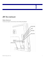
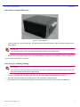
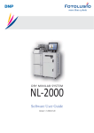
HP TOUCHSMART
WIRING DIAGRAM
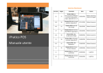
To ensure your system is set up correctly, use the following wiring diagram.
DNP Photo Imaging America Corp.
1
Connecting Power Source
Basic Maintenance
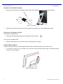
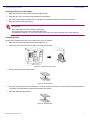
CONNECTING POWER SOURCE
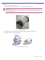
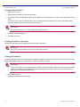
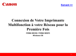
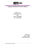
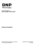
1. Plug the power cord into the AC adapter (brick), and the power adapter cord into the back of the computer.
Figure 1. AC Adapter
2. Plug the power cord into an AC power source through a surge protector or uninterruptible power supply.
Turning the TouchSmart ON/OFF
To turn the HP TouchSmart ON:
1. Press the Power/Sleep button (A) on the top-right side of the computer.
To turn the HP TouchSmart OFF:
2. Follow the instructions in the Tomo User Guide for shutting down the system.
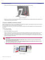
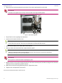
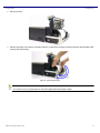
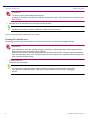
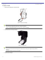
CABLE MANAGEMENT
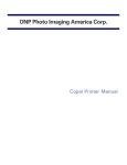
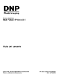
The HP TouchSmart includes a cable-management feature that is located behind the back connector cover.
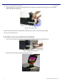
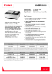
1. To remove the connector cover on the back of the computer, insert your finger under the gap on the bottom-left side
of the cover, and pull gently.
Figure 2. Connector Cover
2
DNP Photo Imaging America Corp.
Cleaning the HP TouchSmart Screen
Basic Maintenance
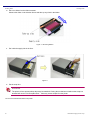
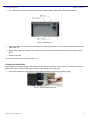
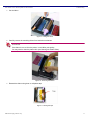
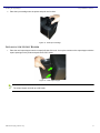
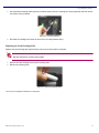
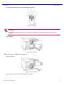
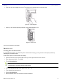
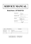
2. Route your cable through the cable routing clip (A), and out of the back of the computer.
Figure 3. Routing Clip
3. Replace the connector cover by aligning the hooks on the right edge of the cover with the slots on the computer, and
then pressing it until it snaps into place.
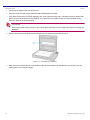
CLEANING THE HP TOUCHSMART SCREEN
Before cleaning the touch screen, you must disable it by turning off the computer. If the computer is not turned off, the touch
screen is enabled, and you could lose data while cleaning it.
For optimal touch performance, the screen requires periodic cleaning to remove any particles on the sides and surface of
the screen.
To clean the touch screen:
1. Turn off the computer.
2. Disconnect the power cord from the wall.
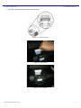
3. Spray a small amount of a mild glass cleaner onto the cleaning cloth that came with your HP TouchSmart. You can
also use a soft cloth or paper towel dampened with a typical household glass cleaner to clean the touch screen.
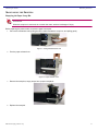
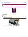
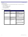
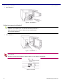
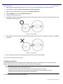
4. Wipe the surface and each side of the touch screen to remove any dirt, fingerprints, or other debris that could hinder
the touch recognition of the screen.
Attention
Do not spray or place cleaner directly on the screen. Spray the cleaner into the cloth, and then wipe the
sides and surface of the touch screen.
Do not use an abrasive cleaner or cloth when cleaning the sides or the surface of the screen, because
this could cause damage to the touch screen.
Figure 4. Cleaning
DNP Photo Imaging America Corp.
3
Calibrating the Touch Screen
Basic Maintenance
CALIBRATING THE TOUCH SCREEN
To calibrate the screen of the HP TouchSmart computer, complete the following steps:
1. Clean the screen before starting a calibration.
2. Log out of SiteKiosk and exit all applications to access the Windows desktop.
3. Click or tap Start on the task bar, and then click Control Panel.
4. In the Control Panel, click or tap Hardware and Sound.
5. Click or tap HP Touch Screen Configuration.
6. Click or tap the Troubleshooting tab.
7. Under Calibration, click or tap Calibrate.
8. Click or tap Yes on the message that opens.
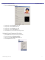
9. Press and hold the crosshair (fingerprint icon) each time it appears until you hear a beep. Do not change the screen
orientation, desktop resolution, or perform any other task until completing calibration.
10. Click or tap Yes to accept these calibration settings.
The screen has been calibrated.
11. If touch points remain inconsistent, shut down the computer and unplog the power cord.
Leave the power cord disconnected for at least 5 seconds.
12. Plug in the power cord and turn on the computer.
Screen calibration is returned to its factory setting. If touch points remain inconsistent, continue to the next step.
13. Close any open software so that the Windows desktop is visible.
14. Press the SCROLL LOCK key on the keyboard 5 times.
15. Touch anyware on the screen and the mouse pointer moves to the upper left.
16. Obtain a pencil that has a clean eraser on one end.
17. Gently touch the eraser to the mouse pointer and hold it until a beep is heard.
18. Release the eraser and the mouse pointer travels to another area of the screen.
19. Continue touching the eraser to the mouse pointer and releasing it until the mouse pointer moves to the center of the
screen.
Repeat these steps if touch points are inconsistent.
4
DNP Photo Imaging America Corp.
2
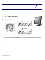
ELO 1715L MONITOR
MONITOR CONNECTIONS
1. Connect one end of the power cord to the monitor and the other end to an outlet.
2. Connect one end of the touchscreen USB cable to the rear side of the computer and the other end to the monitor.
3. Connect one end of the video cable to the rear side of the computer and the other to the LCD monitor.
4. Press the power button on the front panel to turn the monitor on.
DNP Photo Imaging America Corp.
7
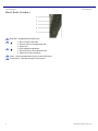
Front Panel Controls
Basic Maintenance
FRONT PANEL CONTROLS
Menu/Exit – Display/Exits the OSD menus.
1. Enter contrast of the OSD.
2. Increase value of the adjustment item.
3. Select item
1. Enter brightness adjustment.
2. Decrease value of the adjustment item.
3. Select item counter-clockwise.
Select – Selects the adjustment items from the OSD menus.
Power Switch – Switches the power of the monitor.
8
DNP Photo Imaging America Corp.
Troubleshooting
Basic Maintenance
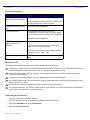
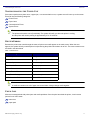
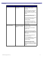
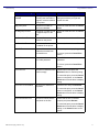
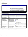
TROUBLESHOOTING
Problem
Suggestion(s)
The monitor does not respond
after you turn on the system.
Check that the monitor’s power switch is on.
Turn off the power and check the monitor’s power cord
and signal cable for the proper connection.
Characters on the screen are
dim.
Adjust the monitor’s brightness.
The screen is blank.
During operation, the monitor screen may
automatically turn off as a result of the power saving
feature. Press any key to see if the screen reappears.
Adjust the monitor’s brightness.
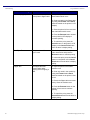
Screen flashes “Out of
Range” display when
initialized.
Turn the monitor off then turn it on again.
Check to see if the resolution of your computer is
higher than that of the LCD display.
Reconfigure the resolution of your computer to make it
less than or equal to 1280 x 1024.
Touch doesn’t work.
Make sure the touch cable is securely attached at both
ends.
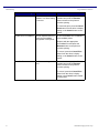
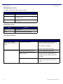
MAINTENANCE
The following tips will help keep your touch monitor functioning at the optimal level.
To avoid risk of electric shock, do not disassemble the touch monitor. There are no user-serviceable parts inside the
monitor. Remember to unplug the touch monitor from the power outlet before cleaning.
Do not use alcohol (methyl, ethyl, or isopropyl) or any strong solvent. Do not use thinner or benzene, abrasive
cleaners or compressed air.
To clean the touch monitor housing, use a cloth slightly dampened with a mild detergent.
Avoid getting liquids inside your touch monitor. If liquid does get inside, have a qualified service technician check it
before you power it on again.
Do not wipe the touchscreen with anything abrasive that could scratch the surface.
To clean the touchscreen, use window or glass cleaner. Put the cleaner on a clean cloth and wipe the touchscreen.
Never apply the cleaner directly on the touchscreen.
Calibrating the Touchscreen
1. Clean the screen before starting a calibration.
2. Log out of SiteKiosk and exit all applications to access the Windows desktop.
3. Click on the Start Menu and go to Control Panel.
4. Double-click Elo Touchscreen.
DNP Photo Imaging America Corp.
9
Calibrating the Touchscreen
Basic Maintenance
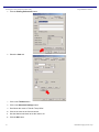
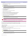
5. On the General Tab, click the Align button.
Figure 2. Elo Touchscreen Properties
6. Touch and release the upper left target. The target should jump to the lower right.
7. Touch and release the lower right target. The target should jump to the upper right.
8. Touch and release the upper right target. The target should jump to the lower left.
9. Touch and release the green check mark. The check screen should disappear.
10. The cursor should now jump to the point of each touch.
11. If the Elo Control Panel is open, close it. Close the Windows Control Panel.
You have now calibrated the touchscreen.
10
DNP Photo Imaging America Corp.
3
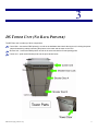
DS TOWER UNIT (NO BACK PRINTER)
The DS Tower unit is made up of three components:
Control Unit – houses the DS80 printer(s), as well as the hardware that controls the tower unit, including the power
strip and networking cables connecting the printers to the tower and the tower to the CPU
Shooter Unit – houses the DS40 printers as well as the sorter mechanism for transporting prints
Corner Unit – spits out the finished prints into the print catcher below
DNP Photo Imaging America Corp.
11
Inside the Tower
Tower Unit
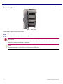
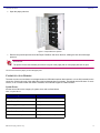
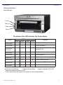
INSIDE THE TOWER
Figure 1. Inside Tower
Inside the tower there are up to four printers:
1-4 DS40 (4x6) printers
Up to 3 DS80 (8x10) printers in the bottom 3 bays
Attention
It is important that these printers are installed in the correct order. Failure to install the printers in their correct
bays could result in corruption of the firmware.
Note
For more information on the printers, see the chapter on DS printers.
12
DNP Photo Imaging America Corp.
Cleaning the Tower Unit
Tower Unit
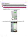
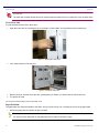
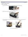
CLEANING THE TOWER UNIT
About once a month, it will be necessary to clean the air filters in the tower unit to maintain optimum performance.
Attention
If the filter is clogged, the internal temperature of the housing becomes higher and can cause errors in printing.
1. Power down the unit and unplug it from the wall.
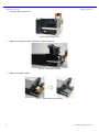
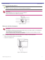
2. Using a Phillips head screwdriver, remove the wire housing from the back of the tower unit buy loosening the two
screws on the side of the tower unit. You do not have to remove the screws entirely.
Figure 1. Remove Screws from Side of Printer
3. Pull the cover towards you until you can remove the panel by sliding the tabs from the back of the printer.
Figure 2. Panel Tabs
DNP Photo Imaging America Corp.
13
Cleaning the Tower Unit
Tower Unit
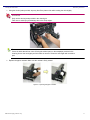
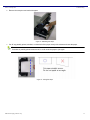
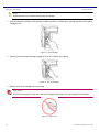
4. Remove the top and bottom panels from the back of the tower exposing the fan units inside.
Attention
The sides of the panels may be sharp. Take care when removing the back panels.
Figure 3. Back Panel Exposed
5. Pop off the fan cover by pulling from the bottom.
6. Vacuum the fan blades and filter cover.
Note
The air filters are very thin. Take care not to damage the air filters with the vacuum.
7. Replace the fan when you are done. Move to the next fan.
8. When you have vacuumed all the fans, replace the back panels.
Note
There is no particular order to replacing the back panels, but make sure you place the panels with
the holes for the wire cover box on the bottom.
Attention
Do not pinch or cut the wires when replacing the panel.
9. Replace the wire cover by first inserting the tabs into the holes in the back panel, and then moving the box so that the
indentions for the screws line up with the screws.
10. Make sure no wires are being pinched by the box. Tighten the screws.
11. Plug the unit in and power the unit back on.
You have now cleaned the air filters on the tower unit.
14
DNP Photo Imaging America Corp.
Troubleshooting the Tower Unit
Tower Unit
TROUBLESHOOTING THE TOWER UNIT
If the tower experiences a printer error, a paper jam, or a communication error, a system error will come up on the screen.
Errors fall into the following categories:
Printer Errors
Paper Jams
Communication Errors
System Errors
Note
The printers will need to cool off periodically. The system will notify you when the printer is cooling,
and the printer will resume printing in approximately 10 to 15 seconds.
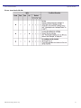
PRINTER ERRORS
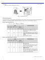
Because the printers are routed through the tower, all printer errors will appear on the main screen. When the error
appears, the system will tell you which printer is experiencing the problem and what to do to fix it. The most common errors
are listed in the table below.
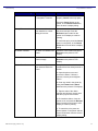
Table 1: Printer Errors
System Message
Solution
End of Paper
Change media set
End of Ribbon
Change media set
Cover is Open
Close front of printer
Paper Jam in Printer
Clear paper jam
Printer Ribbon Jam in Printer
Clear ribbon jam
Ribbon Tension Error
Reset ribbon
Scrap Box is Missing
Replace scrap box
USB Connection Failed
Check USB connection on printer
Note
A media set contains one roll of paper and a new ribbon. Always change media together.
PAPER JAMS
Most error messages deal with printer jams and media problems. Once the print has exited the printer, it can become
jammed in two main areas:
tower door
paper path
DNP Photo Imaging America Corp.
17
Tower Door Jam
Tower Unit
Attention
The tower will not allow another print to be send through the system if there is a paper jam in any of these areas.
Tower Door Jam
If a print becomes jammed in the tower door:
1. Open the tower door by unlocking the door, pressing in on the handle, and the pulling the door towards you.
Figure 1. Opening the Tower Door
2. Look inside the door to find the print.
Figure 2. Inside the Tower Door
3. Remove the print, and then close the door, pressing firmly to ensure it is closed correctly. Relock the door.
4. The printer will reset.
You have now cleared a paper jam from the tower doors.
Paper Path Jam
The paper path runs along the outside of the doors, and up into the corner unit. If a paper jam occurs in the paper path:
1. Unlock the paper path door where the jam is located.
Note
You need to unlock both locks on the paper path door in order for the door to open.
18
DNP Photo Imaging America Corp.
Communication Errors
Tower Unit
2. Open the paper path door.
Figure 3. Paper Path Door Opened
3. Remove the jammed print and close the Paper Path Door and relock the door, holding the door shut with slight
pressure.
Attention
The printer will not send another print if there is a print in the paper path or if the paper path door is open.
You have now cleared a paper jam from the paper path.
COMMUNICATION ERRORS
The most common communication error happens when a USB cable has been disconnected, or is not fully inserted into the
connection. Check both ends of the cable (when able) and reseat them if necessary. This should resolve the issue. If errors
reoccur, or do not resolve when the cable is reseated, call Technical Support at 1-888-749-3587.
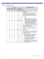
System Errors
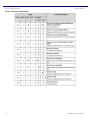
All other errors fall into the category of system errors and are listed below:
Table 2: System Errors
System Message
Solution
Head Voltage Error
Reset printer (turn off/on)
Head Position Error
Reset printer
Power Supply Fan Stopped
Reset printer
Cutter Error
Reset printer
Pinch Roller Position Error
Reset printer
Abnormal Head Temperature
Allow printer to cool, reset printer
DNP Photo Imaging America Corp.
19
Replacing Tower Media
Tower Unit
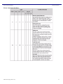
Table 2: System Errors
System Message
Solution
RFID Module Error
Check printer media, reset printer
If any of these errors persist, call Technical Support.
Attention
If any of the errors in Table 3 occur, call Technical Support immediately.
Table 3: System Errors (Cont.)
System Message
Solution
System Error
Call Technical Support
Firmware Error
Call Technical Support
Device Error while Transferring
Firmware Data
Call Technical Support
Error while Sending Firmware Update
Call Technical Support
REPLACING TOWER MEDIA
Note
For more information on replacing media in the DS printers, look in the Installing Media section of
the Printers manual.
20
DNP Photo Imaging America Corp.
4
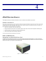
DS40 PRINTER BASICS
This chapter provides you with basic information on how to maintain and troubleshoot your printer.
GENERAL MAINTENANCE
Part of the normal maintenance cycle for printers includes removing dust buildup fro the printer vents. This is done to free
ventilation holes from dust and foreign matter and to improve printer longevity. the following instructions are written in a
generic fashion to include all printers for the systems:
1. Power OFF the system at the main power source.
2. Using a small hand vacuum with a non-metallic extension and nozzle, vacuum all of the printers ventilation ports.
3. Vacuum the base of the system and external ventilation ports.
4. Power ON the system and remaining components.
You have now performed basic maintenance on the printer.
DS40 AND DS80 PRINTERS
Distinguishing Your DS40 and DS80 Printer Model
The DS series are versatile photo printers for use in photo labs by professional photographers, or in other commercial
situations which demand high speed and exceptional quality. Other information on the printers can be found in the printer’s
field service manual or your system’s documentation suite.
Figure 1. The DS40 or DS80 printer
DNP Photo Imaging America Corp.
21
Distinguishing Your DS40 and DS80 Printer Model
Printer Basics
Attention
Prior to moving the printer, the ink ribbon cassette and paper roll should be removed from the printer. Always
take care when lifting the printer so as not to cause physical injury.
When reinstalling, check that the ribbon and paper are properly positioned before resuming printing. If either is
positioned incorrectly, paper jams, print position errors, or other unexpected problems can occur.
The DS40 and DS80 printers are quite similar. The instructions written for one will work for the other. The main difference is
in paper size; DS40 printers print 4x6 size prints, and DS80 printers print 8x12 size prints.
Note
If your printer is configured for use in a tower system, the printer will have small rubber feet. These
feet are essential to aligning the output for the printer with the tower conveyor system and keeping
the printer from moving inside the unit. Do not remove the feet.
22
DNP Photo Imaging America Corp.
Installing Media
Installing Media
INSTALLING MEDIA
Use the following procedures with your DS40 and DS80:
Installing the Paper Roll and Ribbon
Note
It is a good idea to check that there is enough paper in the printer to meet anticipated demand.
Avoid touching the surface of the paper. Excessive fingerprints or smudges can lead to poor print
quality.
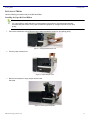
1. Pull out the mechanism unit by lifting the blue handle beneath the scrap box, and pulling gently.
Figure 1. Pulling the Mechanism Unit
2. Free the paper release lever.
Figure 2. Paper Release Lever
3. Remove the scrap box, empty scraps into the trash.
Set aside.
Figure 3. Removing the Scrap Box
DNP Photo Imaging America Corp.
23
Installing Media
Installing Media
4. Remove the spool ends from the printer.
5. Set the spools into the paper, ensuring there is no gap between the paper and the spool.
Attention
Failure to set the paper correctly can result in print jams. Do not get dirt or fingerprints on the paper, as they will
adversely affect print quality.
Figure 4. Paper Roll
6. Set the paper holder into the paper cassette in the printer. Make sure you set the paper in firmly.
7. Set the paper so that it is in the direction shown.
Figure 5. Inserting paper into cassette
24
DNP Photo Imaging America Corp.
Installing Media
Installing Media
8. Remove the seal
9. Advance the paper in the direction indicated. When it is inserted far enough, the buzzer will beep and the paper LED
(orange) will stop blinking.
Figure 6. Advancing the paper
Note
It is easier to set if you press down on the spool lightly while advancing the paper.
DNP Photo Imaging America Corp.
25
Installing Media
Installing Media
10. Set a new ribbon into the ribbon cassette.
Advance the ribbon in the direction shown and take up any slack in the ribbon.
Figure 7. Advancing Ribbon
11. Set it with the supply side in the front.
Figure 8.
12. Set the scrap box.
Attention
The printer will not operate without the scrap box attached. Closing the mechanism unit without the scrap box
attached will cause a “No Scrap Box Error.” Clean any excess scraps from the printer.
You have now installed the media in the printer.
26
DNP Photo Imaging America Corp.
Maintaining the Printers
Maintaining the Printers
MAINTAINING THE PRINTERS
Emptying the Paper Scrap Bin
Attention
When the scrap box is removed, do not touch the cutter, as there is a danger of injury.
Before replacing the printer media, remove the paper’s scrap bin.
1. Pull out the mechanism unit by lifting the blue handle beneath the scrap box, and pulling gently.
Figure 1. Pulling the Mechanism Unit
2. Free the paper release lever.
Figure 2. Paper Release Lever
3. Remove the scrap box, empty scraps into a proper receptacle...
4. Replace the scrap bin.
DNP Photo Imaging America Corp.
27
Cleaning the Ventilation Area
Maintaining the Printers
Attention
The printer will not operate without the scrap box.
Closing the mechanism unit without the scrap box attached will cause a “No Scrap Box Error,” and the red error
LED will blink.
5. Close the top of the mechanism unit, and push unit back in place.
Note
Closing the mechanism unit starts initialization (4 blank sheets are fed out).
You have now performed basic maintenance on the printer.
Cleaning the Ventilation Area
Periodically, you should check the ventilation or exhaust for the printer, as it can become clogged with dust.
Attention
If the ventilation for the printer becomes clogged or blocked, the inside temperature of the housing becomes
higher and can cause the thermal head to overheat.
When the thermal head overheats, printing halts and the power LED will blink. Printing resumes automatically
when the head temperature cools. The thermal head can also overheat due to inputting continuous high-power
such as printing all black images.
1. Turn the printer OFF.
Access the rear of the printer.
Note
You may need to unplug the power or network cables to completely access the back of the printer.
If you will have to disconnect power, make sure you power down the unit previous to unplugging
the unit.
28
DNP Photo Imaging America Corp.
Cleaning the Platen Roller
Maintaining the Printers
2. The exhaust for the printer is located near the top of the back plate, as indicated in the illustration below:
Figure 3. Ventilation Port
3. Wipe the dust from the unit using a cloth designed for dusting electronics, or use canned air to blow the dust from the
back of the unit.
4. Replace any cables you may have had to disconnect to access the back of the printer, and put the printer back in
place.
5. Power the unit ON.
You have now cleaned the dust from the ventilation unit.
Cleaning the Platen Roller
If any impressions appear regularly in the same place on the prints, on either the front or back, you will need to clean the
platen roller. There could be powder, paper scraps, or other debris stuck to the roller.
1. Pull out the mechanism unit by lifting the blue handle beneath the scrap box, and pulling gently.
Figure 4. Pulling the Mechanism Unit
DNP Photo Imaging America Corp.
29
Cleaning the Platen Roller
Maintaining the Printers
2. Free the paper release lever.
Figure 5. Paper Release Lever
3. Remove the scrap box, empty scraps into a proper receptacle...
Figure 6. Removing the Scrap Bin
4. Remove the paper cassette.
Figure 7. Removing the Paper Cassette
30
DNP Photo Imaging America Corp.
Cleaning the Platen Roller
Maintaining the Printers
5. Using the alcohol pads provided, wipe any dirt off the platen roller while rotating the roller slightly.
Attention
Only use the alcohol pads provided in the cleaning kit.
Take care to avoid injury and damage due to the sharp edges.
Note
If there is debris that will not come off using the alcohol pad, run the sandpaper provided in the
cleaning kit over the area lightly until the debris is removed. Clean the area again with an alcohol
pad.
6. Replace the paper cassette. Make sure the casette is firmly seated.
Figure 8. replacing the paper cassette.
DNP Photo Imaging America Corp.
31
Cleaning the Platen Roller
Maintaining the Printers
7. Advance the paper in the direction indicated until the buzzer beeps, and orange Paper LED stops blinking.
Figure 9. Advancing the paper
8. Replace the scrap bin and close the top of the mechanism.
9. Gently slide the mechanism back in place. The printer will re-initialize.
You have now cleaned the platen roller.
32
DNP Photo Imaging America Corp.
Troubleshooting
Troubleshooting
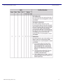
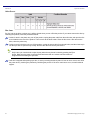
TROUBLESHOOTING
Error Messages
Power
Ribbon
Paper
Error
The status of the LED indicates the Printer Status
Status
Power
LED Display
Ribbon Paper
Out of Paper*
z
Out of Ribbon*
z
Door is open
(No Paper)
z
{
Door is open
z
{
No scrap box
z
Paper Error
z
Ribbon Error
z
System Error**
z
Over-heated
{
Error
Put in a new roll of paper
{
Put in a new ribbon
{
z
z
Solution
Set the paper properly, and close the
mechanism unit
{
Close the mechanism unit
{
Set the scrap box
z
Reset the paper roll correctly
z
Reset the ribbon correctly
z
Turn the power OFF, then back ON
The head is cooling off (auto-recovery)
z indicates lit, not blinking
{ indicates lit and blinking
empty box indicates LED is OFF
* Replace the paper and ribbon as a SET
** If you cannot resolve the system error, contact your service representative
DNP Photo Imaging America Corp.
33
Resolving Media Errors
Troubleshooting
RESOLVING MEDIA ERRORS
If there is a Paper Jam:
1. Pull out the mechanism unit by lifting the blue handle beneath the scrap box, and pulling gently.
Figure 1. Pulling the Mechanism Unit
2. Remove the ribbon cassette by pulling the cassette up and out.
Figure 2. Removing the Ribbon Cassette
3. Pull any paper remaining in the printer in the direction indicated, and cut off any wrinkled or partially printed areas
evenly with scissors.
Figure 3. Pulling and Trimming the Paper
34
DNP Photo Imaging America Corp.
If there is a Paper Jam:
Troubleshooting
4. Remove the scrap box and rewind the paper.
Figure 4. Rewinding the Paper
5. Cut off any partially printed, wrinkled, or otherwise inferior paper evenly with scissors and reset the paper.
Note
If wrinkles or partially printed areas are left, it could cause the paper to jam again.
Figure 5. Cutting the Paper
DNP Photo Imaging America Corp.
35
If the ribbon is torn or has been pulled into the mechanism:
Troubleshooting
6. Advance the paper in the direction indicated. When it is inserted far enough the buzzer will beep, and the orange
Paper LED light will stop blinking.
Figure 6. Advancing the paper
Close the top of the mechanism, and push the mechanism back in place. The printer will re-initialize.
You have now cleared a paper jam.
If the ribbon is torn or has been pulled into the mechanism:
1. Pull out the mechanism unit by lifting the blue handle beneath the scrap box, and pulling gently.
Figure 7. Pulling the Mechanism Unit
2. Carefully remove the ribbon cassette by pulling up and out.
Figure 8. Removing the Ribbon Cassette
36
DNP Photo Imaging America Corp.
If the ribbon is torn or has been pulled into the mechanism:
Troubleshooting
3. Cut the ribbon.
Figure 9. Cutting the ribbon
4. Carefully remove the remaining ribbon from inside the mechanism.
Attention
If the ribbon is torn or left in the printer, it could affect print quality.
You may need to clean the platen roller (see Cleaning the Platen Roller).
Figure 10. Removing the Ribbon
5. Reattach the ribbon using clear or cellophane tape.
Figure 11. Placing the tape
DNP Photo Imaging America Corp.
37
If the ribbon is torn or has been pulled into the mechanism:
Troubleshooting
6. Advance the ribbon several times as shown, until the tape is out of sight.
Attention
Make sure there is NO slack in the ribbon.
Always wind ribbon onto the orange take-up spool.
Figure 12. Advancing the ribbon
7. replace the cassette.
Attention
Make sure the ribbon is placed in the printer correctly, inserting the take-up side first. If the cassette is inserted
improperly, the mechanism will not close.
Figure 13. Replacing the Cassette.
8. Close the mechanism. The printer will re-initialize.
You have now repaired a torn ribbon.
38
DNP Photo Imaging America Corp.
If the Printer is Stopped Mid-action:
Troubleshooting
If the Printer is Stopped Mid-action:
Figure 14. Printer Stopped
1. Turn the power OFF, and then back ON. The jammed paper should be released, and the cutter should return to its
ready position
Attention
The mechanism will not open until the cutter has been returned to the ready position.
2. Remove any partially printed paper from inside the mechanism, following the instructions for “if there is a paper jam.”
You have reset a printer stopped in mid-action.
If the Power is Cut During Printing:
Attention
If the power is cut during printing, the mechanism unit cannot be pulled out. The mechanism will not open until
the cutter has been returned to the ready position.
1. Turn the power back ON. The partial print will be cut into scrap lengths and discarded in the scrap bin.
2. Once the cutter has returned to the ready position, the mechanism can be pulled out.
3. Check that there is no partially printed paper in the mechanism unit. If there is, see: “if there is a paper jam.”
DNP Photo Imaging America Corp.
39
If the Power is Cut During Printing:
40
Troubleshooting
DNP Photo Imaging America Corp.
5
EPSON RECEIPT PRINTER (TMT88IV)
INSTALLING MEDIA
Installing the Paper Roll
To install paper for the first time or to replace a used paper roll, follow these steps:
Note
Do not use paper rolls that have the paper glued or taped to the core because they might cause a
paper jam.
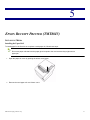
1. Open the paper roll cover by pushing the printer cover button.
2. Remove the used paper roll core if there is one.
DNP Photo Imaging America Corp.
41
Installing the Paper Roll
Receipt Printer
3. Insert the paper roll as shown.
Figure 1. Insert Paper Roll
4. Make sure the leading edge of the paper is at the bottom of the roll.
Figure 2. Leading Edge of Roll
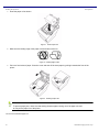
5. Pull out a few inches of paper. Close the cover and tear off the extra paper by pulling it towards the front of the
printer.
Figure 3. Installing Paper Roll
Note
To prevent paper jams, make sure that nothing obstructs paper coming out of the paper exit, and
do not pull the paper out of the printer.
You have now installed a paper roll.
42
DNP Photo Imaging America Corp.
Receipt Printer Maintenance
Receipt Printer
RECEIPT PRINTER MAINTENANCE
Cleaning the Thermal Print Head
Attention
After printing, the printhead can be very hot. Be careful not to touch it.
Let the printhead cool before you clean it.
1. Open the paper roll cover.
2. Clean the thermal element (the green part) of the printhead with a cotton swab moistened with an alcohol solvent
(ethanol, methanol, or IPA).
Note
Clean the thermal head every three months to maintain receipt printer quality.
You have now cleaned the thermal print head.
TROUBLESHOOTING
Removing a Paper Jam
Attention
Do not touch the paper feed motor because it can be very hot.
If the paper is jammed in the paper roll section:
1. Turn the printer off.
2. Open the paper roll cover, remove the paper roll, and remove the jammed paper.
3. Insert the paper roll. Make sure the paper roll is seated correctly and close the cover.
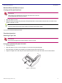
4. If paper is caught in the cutter and you cannot open the printer cover, open the cutter cover as shown below.
Figure 4. Cutter Cover
English
DNP Photo Imaging America Corp.
43
The Control Panel
Receipt Printer
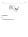
5. Turn the knob until you see a triangle in the opening. This returns the cutter blade to the normal position.
There is a label near the cutter to assist you. (see below)
6. Close the cutter cover.
7. Open the printer cover and remove the jammed paper.
You have now removed a paper jam.
THE CONTROL PANEL
This section explains the symbols and buttons on the control panel of the receipt printer.
Power – This light is on whenever the power is turned on.
Error – This light indicates an error.
Paper Out – This light comes on when the printer is out, or nearly out of paper.
Feed – Use this button to feed the paper out of the printer.
44
DNP Photo Imaging America Corp.
6
FARGO HDP5000 CARD PRINTER
INCLUDED WITH YOUR PRINTER:
power supply
input card cartridge
output hopper
cleaning roller & spindle
Attention
Place the printer unit in a location with adequate air circulation.
Do no install the printer near heat sources, such as radiators or air ducts, or in places subject to direct sunlight or
excessive dust.
Attention
Before beginning installation, make sure to unplug the power supply and USB/ethernet cables from the printer.
DNP Photo Imaging America Corp.
47
Configuring the HDP5000 Card Printer
Fargo HDP5000 Card Printer
CONFIGURING THE HDP5000 CARD PRINTER
Follow these instructions for establishing the correct printer settings for the Fargo Card Printer.
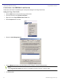
Setting the Fargo Color Profile
1. Click the Start button in the lower left corner of the screen.
2. From the Start menu select Printers and Faxes.
3. Right-click on the Fargo HDP5000 Card Printer icon.
4. Select Properties from the menu.
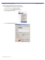
5. Select the Color Management tab.
6. Click the Manual radio button to prohibit Windows from making an automatic profile selection.
Note
If the Fargo 343 Feb 3 2009 color profile is not available in the list of choices, it must be added.
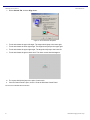
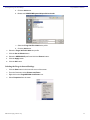
7. To add the profile:
48
DNP Photo Imaging America Corp.
Selecting the Fargo Advanced Settings
Fargo HDP5000 Card Printer
a. Click the Add button.
b. Browse to C:\WINDOWS\system32\spool\drivers\color
c. Select the Fargo 343 Feb 3 2009 color profile.
d. Click the Add button.
8. Select the Fargo 343 Feb 3 2009 color profile.
9. Click the Set as Default button.
10. Select the HDP5000CLR profile and click the Remove button.
11. Click the Apply button.
12. Click the OK button.
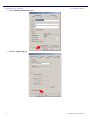
Selecting the Fargo Advanced Settings
1. Click the Start button in the lower left corner of the screen.
2. From the Start menu select Printers and Faxes.
3. Right-click on the FargoHDP5000 Card Printer icon.
4. Select Properties from the menu.
DNP Photo Imaging America Corp.
49
Selecting the Fargo Advanced Settings
Fargo HDP5000 Card Printer
5. Click the Printing Preferences button.
6. Select the Image Color tab.
50
DNP Photo Imaging America Corp.
Selecting the Transfer Temperature Offset Setting
Fargo HDP5000 Card Printer
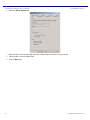
7. Click on the Advanced Settings button.
8. Using the slider, set the Sharpness value to 25.
9. Using the slider, set the Contrast value to 5.
10. Using the slider, set the Gamma value to 30.
11. Using the slider, set the Yellow Balance to 3.
12. Click the OK button to close the Advanced Settings window.
Selecting the Transfer Temperature Offset Setting
1. Click the Start button in the lower left corner of the screen.
2. From the Start menu select Printers and Faxes.
3. Right-click on the Fargo HDP5000 Card Printer icon.
4. Select Properties from the menu.
DNP Photo Imaging America Corp.
51
Selecting the Transfer Temperature Offset Setting
Fargo HDP5000 Card Printer
5. Click the Printing Preferences button.
6. Select the Card tab.
7. Click on the Toolbox button.
8. Click on the Advanced Settings button.
9. Scroll down the menu to Transfer Temp Offset.
10. Click on the value in the Current column.
11. Use the down arrow button to set the value to -5.
12. Click the OK button.
52
DNP Photo Imaging America Corp.
Setting the Device Settings for Photo Card Printing
Fargo HDP5000 Card Printer
Setting the Device Settings for Photo Card Printing
1. Click the Start button in the lower left corner of the screen.
2. From the Start menu select Printers and Faxes.
3. Right-click on the Fargo HDP5000 Card Printer icon.
4. Select Properties from the menu.
5. Click the Printing Preferences button.
DNP Photo Imaging America Corp.
53
Setting the Device Settings for Photo Card Printing
Fargo HDP5000 Card Printer
6. Select the Device Options tab.
7. Check the box next to Automatically detect the installed Ribbon and Film for every print job.
8. Check the box next to Print Both Sides.
9. Click the OK button.
54
DNP Photo Imaging America Corp.
Loading Media
Fargo HDP5000 Card Printer
LOADING MEDIA
To load film and ribbon into the printer:
1. Push in on the front cover to open it.
Figure 1. Open Front Cover
Figure 2. Cover Open
2. Remove the HDP film cartridge and print ribbon cartridge.
Figure 3. Remove Cartridges
DNP Photo Imaging America Corp.
55
Loading Media
Fargo HDP5000 Card Printer
3. Load the HDP film into the HDP film cartridge until the rolls click.
Figure 4. Load Film
Note
The film spindles and cartridge gears are color coded to ensure correct placement of the film.
4. Tighten the film by rotating the rolls in the directions indicated below.
Figure 5. Tighten Film
5. Insert the HDP film cartridge back into the printer until it clicks.
6. Load the print ribbon into the print ribbon cartridge until the rolls click.
Figure 6. Load Print Ribbon
56
DNP Photo Imaging America Corp.
Loading Media
Fargo HDP5000 Card Printer
Note
The ribbon spindles and the cartridge gears are color coded to ensure correct placement of the
ribbon.
7. Tighten the print ribbon by rotating the rolls in the directions indicated below.
Figure 7. Tighten the Ribbon
8. Insert the print ribbon cartridge into the printer until it clicks.
Figure 8. Both Cartridges Inserted
9. Close the printer front cover.
DNP Photo Imaging America Corp.
57
Loading the Cleaning Roller
Fargo HDP5000 Card Printer
LOADING THE CLEANING ROLLER
1. Remove the card cleaning roller from the print ribbon packaging and insert the cleaning roller onto the cleaning roller
spindle from the supply pack.
Figure 9. Cleaning Roller
Attention
The cleaning roller spindle comes with the printer, not with each ribbon package.
DO NOT discard the cleaning roller spindle.
2. Remove the protective sleeve from the card cleaning roller.
Figure 10. Remove Sleeve
58
DNP Photo Imaging America Corp.
Loading the Cleaning Roller
Fargo HDP5000 Card Printer
3. Insert the card cleaning roller into the card input area.
Figure 11. Location on Printer
Figure 12. Insert Roller
Figure 13. Roller Installed
DNP Photo Imaging America Corp.
59
Loading Cards
Fargo HDP5000 Card Printer
LOADING CARDS
1. Pull the input cartridge open as shown below.
Figure 14. Open Input Cartridge
Note
The card input cartridge will remain open if opened completely.
There is a loading guide graphic on the top cover of the input cartridge.
2. Load cards into the card input cartridge.
Figure 15. Loading Cards
Note
The front of the card should be facing down. The back of the card (or the magnetic strip) should be
facing up.
The input cartridge can hold up to 100 cards.
3. Close the input cartridge.
60
DNP Photo Imaging America Corp.
Installing the Output Hopper
Fargo HDP5000 Card Printer
4. Place the input cartridge onto the printer and push until it clicks.
Figure 16. Install Input Cartridge
INSTALLING THE OUTPUT HOPPER
1. Place the card output hopper onto the output (left) side of the unit. Line up the notches on the output hopper with the
square openings on the printer and push down until it clicks.
Figure 17. Card Output Hopper
Note
The output hopper can hold up to 200 cards.
DNP Photo Imaging America Corp.
61
Cleaning the Printer
Fargo HDP5000 Card Printer
CLEANING THE PRINTER
Some cleaning processes require you to access the Toolbox dialog display. To access the toolbox:
1. Click on the Start menu.
2. Navigate to Control Panel > Printers.
3. Right-click on the HDP5000 printer.
4. Select Printing Preferences.
5. Click on the Toolbox button at the bottom of the dialog box.
Attention
Be sure to disconnect the printer’s power cord whenever performing any type of maintenance unless otherwise
directed.
For the maintenance procedures outlines, you will need a Printer Cleaning Kit. This optional kit includes the following:
Printhead Cleaning Swabs – pre-moistened with 99.99% isopropyl alcohol for cleaning the printhead
Cleaning Cards with adhesive backing for cleaning the printer’s cleaning rollers
Gauze Pads pre-moistened with 99.99% isopropyl alcohol for cleaning the printer’s interior/exterior
Alcohol Cards pre-moistened with 99.99% isopropyl alcohol for cleaning the printer’s platen rollers and card feed
rollers
Attention
To prevent equipment or media damage, always remove the ribbon and cards from the printer before making
any repairs, unless otherwise specified.
Attention
To prevent equipment or media damage, take jewelry off of fingers and hands, as well as thoroughly clean hands
to remove oil and debris before working on the printer.
62
DNP Photo Imaging America Corp.
Cleaning the Printer Platen Roller and Card Feed Rollers
Fargo HDP5000 Card Printer
Cleaning the Printer Platen Roller and Card Feed Rollers
Perform this procedure approximately every 1000 prints to maintain a consistent print quality. The card feed rollers move
the card throughout the print process. Rollers should be kept clean to prevent card jams and card contamination.
1. From the HDP5000 Driver, click on the Toolbox button to bring up the Clean Printer tab.
Figure 18. Clean Printer Tab
2. Follow the instructions from the Clean Printer tab on the driver.
Note
If your printer is equipped with a Magnetic Encoder, you must insert the cleaning card with the
printed side up and with a small liner strip towards the front of the printer.
Figure 19. Cleaning Card
3. Replace the printing supplies and close the print stations after the rollers are clean and completely dry.
DNP Photo Imaging America Corp.
63
Cleaning Inside the Printer
Fargo HDP5000 Card Printer
Cleaning Inside the Printer
1. Open the front cover.
2. Remove the print ribbon and film from the printer.
3. If you have a can of compressed air, blow out all visible areas of the printer interior. Remove any debris that may be
inside.
If you do not have a can of compressed air, use a cleaning pad from the cleaning kit to wipe out all visible areas
inside the printer. Remove any debris that may be inside.
Attention
Be extremely careful not to let any alcohol drip inside the printer.
4. Re-install the printing supplies.
5. Close the front cover.
Cleaning the Outside of the Printer
Clean the printer casing with a cleaning pad from the printer cleaning kit.
Attention
Do not use cleaning solvents of any kind or spray with a cleaner.
Cleaning the Printhead
Clean the printhead every time the print ribbon is changed to maintain consistent print quality. This procedure should also
be performed approximately every 1000 prints in order to maintain print quality.
Attention
Never use a sharp tool or abrasive object of any kind to clean the printhead. Watches, rings, bracelets and other
jewelry can damage the printhead if accidently bumped against. For best results, remove such items before
touching any internal parts of the printer.
1. Open the front cover.
2. Remove the ribbon and film cartridges.
64
DNP Photo Imaging America Corp.
Fargo HDP5000 Card Printer
3. Use a printhead cleaning swab (squeeze to saturate the tip) from the cleaning kit to firmly wipe back and forth across
the surface of the printhead.
Figure 20. Cleaning Printhead
4. Re-install the cartridges and close the front cover once the printhead is dry.
Replacing the Card Cleaning Roller
Replace the card cleaning tape approximately every time the print ribbon is changed.
Attention
DO NOT discard the cleaning roller spindle.
1. Remove the card cartridge to access the cleaning roller.
2. Remove the cleaning roller.
Figure 21. Removing Cleaning Roller
You have now completed maintenance on the printer.
DNP Photo Imaging America Corp.
65
Troubleshooting
Fargo HDP5000 Card Printer
TROUBLESHOOTING
Some troubleshooting requires you to access the Printer Preferences dialog box. To access Printer Preferences:
1. Click on the Start menu.
2. Navigate to Control Panel > Printers.
3. Right-click on the HDP5000 printer.
4. Select Printing Preferences.
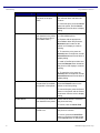
Troubleshooting the Printer Error Messages
Printer Error Message
Cause
Solution
General Error
A general printer error has
occurred.
Press Cancel on the printer or click
on Cancel Print from the driver’s
display dialog.
Card Not Found
The printer is unable to find
the card.
Check the printer for a card or other
obstruction. Remove the card and
cancel the print by pressing the
Cancel button on the printer or the
Cancel Print button from the driver’s
display dialog.
Cover is Open
The printer cannot start
printing because the cover
is open.
Close the cover to continue printing.
Unable to Feed
The printer is unable to feed
a card from the card
cartridge.
Ensure that cards are available and
loaded correctly. Press the Resume
button located on the printers LCD
display to continue printing.
To cancel the print, press the Cancel
button on the printer and the Cancel
Print button from the driver’s display
dialog.
66
DNP Photo Imaging America Corp.
Troubleshooting
Fargo HDP5000 Card Printer
Printer Error Message
Card Jam
Cause
Solution
A card has become jammed
in the printer.
a. Open the printer’s front cover and
remove the ribbon and film
cartridges.
b. Clear any cards in the printer by
using the Forward and/or Back
buttons located on the printer’s LCD
display.
c. Re-insert the ribbon and film and
close the printer’s front cover.
d. Press the Resume button located
on the printer’s LCD display to
continue printing.
e. To cancel the print, press the
Cancel button on the printer and the
Cancel Print button from the driver’s
display dialog.
Card Jam (encoder)
A card has become jammed
in the printer’s encoding
station.
a. Open the printer’s front cover and
remove the ribbon.
b. Open the printer’s dual-sided
module cover.
c. Clear any cards in the encoding
module by using the Forward and/or
Back buttons located on the printer’s
LCD display.
d. Re-insert the print ribbon and
close the front cover.
e. Press the Resume button located
on the printer’s LCD display to
continue printing.
f. To cancel the print, press the
Cancel button located on the
printer’s LCD display or the Cancel
Print button from the driver’s display
dialog.
DNP Photo Imaging America Corp.
67
Troubleshooting
Fargo HDP5000 Card Printer
Printer Error Message
Card Jam (flipper)
Cause
Solution
A card has become jammed
in the printer’s flipper table.
a. Open the printer’s front cover and
dual-sided module cover.
b. Clear any cards in the flipper table
by using the Forward and/or Back
buttons located on the printer’s LCD
display.
c. Close the printer’s front cover and
the dual-sided module cover.
d. Press the Resume button located
on the printer’s LCD display to
continue printing.
e. To cancel the print, press the
Cancel button on the printer’s LCD
display or the Cancel Print button
from the driver’s display dialog.
Card Eject Error
The printer is unable to
eject a card.
Check the printer for a card jam or
other obstruction and press the
Resume button to continue printing.
To cancel the print, press the Cancel
button on the printer or the Cancel
Print button from the driver’s display
dialog.
Flipper Jam
The flipper table has
jammed while either
aligning itself or flipping a
card.
a. Open the printer’s dual-sided
module cover.
b. Clear any cards in the module by
using the Forward and/or Back
buttons located on the printer’s front
cover.
c. Ensure the flipper table can rotate
freely. Close the module cover.
d. Press the Resume button on the
printer’s front cover to continue
printing.
e. To cancel the print, press the
Cancel Print button from the driver’s
display dialog.
68
DNP Photo Imaging America Corp.
Troubleshooting
Fargo HDP5000 Card Printer
Printer Error Message
Ribbon RFID Error
Cause
The ribbon tag information
is corrupted or incorrect.
Solution
Check that the ribbon is installed
properly. Cancel is the only option.
Press the Cancel button on the
printer, or the Cancel Print button
from the driver’s display dialog.
Wrong Ribbon Installed
An incorrect ribbon has
been installed or a driver
setting is incorrect.
Check that the ribbon is correct for
the printer and job. Press the
Resume button located on the
printer’s LCD display to continue
printing.
To cancel the print, press the Cancel
button on the printer, or the Cancel
Print button from the driver’s display
dialog.
No Ribbon Installed
No ribbon is installed in the
printer.
Install the correct ribbon and press
Resume on the printer’s LCD
display.
Ribbon Out
The ribbon installed in the
printer is empty.
Install a new ribbon and press
Resume on the printer’s LCD
display.
Ribbon Break/Jam
A ribbon break/jam has
been detected inside the
printer.
The printer has determined that the
installed ribbon has either jammed or
broken.
a. Open the printer cover and
remove the ribbon. If ribbon is
jammed, remove jam and tighten
ribbon.
b. Clear any cards in the printer by
using the Forward and/or Back
buttons on the printer’s LCD display.
c. Tape the ends of the ribbon
together and wind any excess onto
the take-up spool of the ribbon.
d. Re-install the ribbon, close the
printer cover, and press the Resume
button located on the printer’s LCD
display to continue printing.
e. To cancel the print, press the
Cancel button on the printer and the
Cancel Print button from the driver’s
display dialog.
DNP Photo Imaging America Corp.
69
Troubleshooting
Fargo HDP5000 Card Printer
Printer Error Message
Ribbon Sensor Error
Cause
The printer cannot find the
next panel on the print
ribbon.
Solution
Recalibrate the ribbon sensor using
the calibrate ribbon tab within the
Toolbox.
To cancel the print, press the Cancel
button the printer, and the Cancel
Print button from the driver’s display
dialog.
Invalid Ribbon
An incorrect ribbon has
been installed in the printer.
(This is if you are using a
SecureMark ribbon.)
A non-SecureMark ribbon is installed
in a SecureMark printer.
a. Replace with the appropriate
SecureMark ribbon and press the
Resume button located on the
printer’s LCD display to continue
printing.
b. To cancel the print, press the
Cancel button on the printer, and the
Cancel Print button from the driver’s
display dialog.
c. Install a Certified print ribbon and
press the Resume button located on
the printer’s LCD display to continue
printing.
d. To cancel the print, press the
Cancel button on the printer, and the
Cancel Print button from the driver’s
display dialog.
Invalid Ribbon
The ribbon installed does
not match the SecureMark
configuration of the printer.
Install a certified print ribbon and
press the Resume button on the
printer to continue printing.
To cancel the print, press the Cancel
button on the printer and the Cancel
Print button from the driver’s display
dialog.
Invalid Ribbon
An incorrect print ribbon has
been installed in the printer.
Check that the ribbon is correct for
the printer and retry.
To cancel, click on Cancel Print.
Ribbon Error
The print ribbon caused a
general error.
Press the Resume button located on
the printer to continue.
To cancel, press the Cancel Print
button on the driver’s display dialog
or the Cancel button on the printer.
70
DNP Photo Imaging America Corp.
Troubleshooting
Fargo HDP5000 Card Printer
Printer Error Message
Cause
Solution
No Magnetic Encoder
Installed
A print job with magnetic
encoding was sent with no
magnetic encoder installed
in the printer.
Ensure that no encoding data is
being sent with the print job and
reprint the card.
Mag Verify Error
The printer is unable to
verify encoded data.
Check the cards and click on Cancel
Print.
No Mag Strip Present
The printer is unable to find
a magnetic stripe on the
card.
Check the cards and click on Cancel
Print.
No Smart Card Encoder
No Smart Card encoder is
installed on the printer.
To cancel, click on Cancel Print.
No Prox Card Encoder
No Proximity Card encoder
is installed on the printer.
To cancel, click on Cancel Print.
Headlift Error
The headlift sensor is not
detected movement from
the headlift cam.
Reboot the printer by cycling power.
The password entered is
not a valid password.
Press OK to enter another
password.
Invalid Password
To cancel, press the Cancel Print
button.
To cancel, press the Cancel Print
button.
Print Film Out
The print film installed in the
printer is empty.
Install new film and press the
Resume button to continue printing.
To cancel the print, press the Cancel
button on the printer, or the Cancel
Print button from the driver’s display
dialog.
Print Film is not Installed
No print film is installed in
the printer.
Install the film and press Resume.
To cancel the print, press the Cancel
button on the printer, or the Cancel
Print button from the driver’s display
dialog.
Print Film Sensor Error
The printer cannot find the
next panel on the film.
Check that the film is installed
properly and press Resume.
To cancel the print, press the Cancel
Print button from the driver’s display
dialog, or the Cancel button on the
printer.
DNP Photo Imaging America Corp.
71
Troubleshooting
Fargo HDP5000 Card Printer
Printer Error Message
Cause
Wrong Print Film Installed
An incorrect film has been
installed, or a driver setting
is incorrect.
Solution
Ensure that the appropriate film is
installed and press the Resume
button located on the printer to
continue printing.
To cancel the print, press the Cancel
Print button from the driver’s display
dialog, or the Cancel button on the
printer.
Invalid Print Film Installed
The film installed does not
match the SecureMark
configuration of the printer.
A non-SecureMark film is installed in
a SecureMark printer.
Replace with the appropriate
SecureMark film and press the
Resume button on the printer to
continue printing.
To cancel, press the Cancel Print
button from the driver’s display
dialog, or the Cancel button on the
printer.
Print Film Error
The film caused a general
error.
Ensure that the appropriate film is
installed and press the Resume
button located on the printer to
continue printing.
To cancel, press the Cancel Print
button from the driver’s display
dialog or the Cancel button located
on the printer.
72
DNP Photo Imaging America Corp.
7
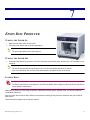
EPSON DISC PRODUCER
TURNING THE POWER ON
1. Make sure the power cable is connected.
2. Press the power button until the power light flashes.
Note
The power light flashes green, then stays on.
TURNING THE POWER OFF
1. Press the power button for more than 1 second. The power light will flash green and then turn off. The power is now
turned off.
Note
The fan will operate after turning the power off, but it will automatically stop after 15 minutes.
If the unit is operating, wait for 10 seconds after operation is stopped to turn off the power.
LOADING DISCS
Attention
The Epson Disc Producer is configured to use CD-R and DVD-R discs. Using any other type of disc may start to
cause operation malfunctions.
Depending on whether you are using the product in Standard, External Output, or Batch mode, you will use a different
combination of stackers.
See your Epson Disc Producer Setup Guide for instructions on setting up the product for operation with your PrintRush
MPL system.
These instructions explain how to load each stacker.
DNP Photo Imaging America Corp.
67
Loading Discs
Epson Disc Producer
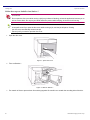
Follow these steps to load discs into Stacker 1.
Attention
Do not open the disc cover while running a job (busy indicator is flashing), unless the application instructs you to
add or remove discs. Do not put your hands inside the product while beeping, as the arm is still moving.
Note
A beep will sound if you open the disc cover while running a job, and the job will pause. Closing
the disc cover automatically resumes the job.
Pause a job if you need to open the disc cover.
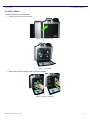
1. Open the disc cover.
Figure 1. Open Disc Cover
2. Take out Stacker 1.
Figure 2. Remove Stacker 1
3. Fan a stack of discs to prevent them from sticking together. Be careful not to scratch the recording side of the disc.
68
DNP Photo Imaging America Corp.
Loading Discs
Epson Disc Producer
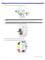
4. Load the discs into Stacker 1 with the printable side facing up.
Figure 3. Load Discs
Attention
Do not load the discs above the red line marked on the stacker; otherwise, the discs or product may be
damaged.
5. Insert Stacker 1.
Figure 4. Insert Stacker 1
Follow these steps to load discs into Stacker 2.
1. Remove Stacker 2.
Figure 5. Remove Stacker 2.
2. Load discs into Stacker 2 with the printable side facing up.
DNP Photo Imaging America Corp.
69
Follow these steps to load Stacker 3.
Epson Disc Producer
3. Insert Stacker 2.
Figure 6. Insert Stacker 2.
Follow these steps to load Stacker 3.
Note
Stacker 3 is an output source. You will not load discs into Stacker 3.
Make sure there are no discs in Stacker 4 when using Stacker 3.
Do not remove Stacker 4.
1. Insert Stacker 3.
Figure 7. Insert Stacker 3
Attention
Be sure to lock the lever located on Stacker 4 when you use Stacker 3 (see below).
Figure 8. Lock Lever
70
DNP Photo Imaging America Corp.
Replacing the Ink Cartridges
Epson Disc Producer
Follow these steps when using Stacker 4:
Note
Stacker 4 is used as an output source. You will not load discs into Stacker 4.
Attention
When using Stacker 4 as an output source, do not use Stacker 3.
Be sure to unlock the lever on Stacker 4 (see below).
Figure 9. Unlock Lever
REPLACING THE INK CARTRIDGES
Attention
For maximum ink efficiency, only remove an ink cartridge when you are ready to replace it. Ink cartridges with
low ink status may not be used when reinserted.
Do not refill the ink cartridges. Other products not manufactured by Epson may cause damage, and under
certain circumstances may cause erratic product behavior.
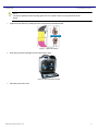
When the ink light is flashing orange you will need to replace the ink cartridge. Follow the steps below:
1. Make sure that the power light is on, but not flashing.
2. Open the ink cartridge cover.
Figure 10. Open Cartridge Cover
DNP Photo Imaging America Corp.
71
Replacing the Ink Cartridges
Epson Disc Producer
Note
Wait 4 seconds or more before removing the ink cartridge.
3. Push the expended cartridge so the cartridge is slightly pushed out. (A flashing ink cartridge light will indicate which
cartridge is low.)
Figure 11. Push Cartridge
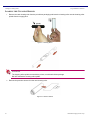
4. Carefully pull the expended cartridge straight out of the slot. Dispose of it properly.
Figure 12. Pull Out Cartridge
5. Remove the new ink cartridge from the package.
Attention
Do not touch the green IC chip on the side of the cartridge (see below). This can damage the ink cartridge.
Figure 13. Don’t Touch
72
DNP Photo Imaging America Corp.
Maintenance
Epson Disc Producer
6. Place the new ink cartridge into the slot. Then push the ink cartridge until it clicks into place.
Figure 14. Push Cartridge In
7. When you are finished replacing cartridges, close the ink cartridge cover.
Figure 15. Close Cover
You have now replaced an ink cartridge.
MAINTENANCE
Checking the Print Head Nozzles
If you find that the printout is unexpectedly faint or that dots are missing, you may be able to identify the problem by
checking the print head nozzles.
Follow these steps to use the Nozzle Check Utility:
1. At the server kiosk, touch and hold the Tomo logo in the upper left corner of the screen.
2. Enter the password 4301. Touch OK.
3. Touch Exit Application.
Note
You will need to connect a keyboard to the system.
4. From the Desktop Security screen, type CTRL + ALT + U.
5. Type d1gital08 as the password.
6. Select Close SiteKiosk.
7. Hit the Windows button. You now have access to Windows.
DNP Photo Imaging America Corp.
73
Cleaning the Print Head
Epson Disc Producer
8. Make sure that an unprinted disc with a 116mm (4.57”) or more outside diameter is installed in Stacker 1.
9. From Windows, navigate to Start > Control Panel > Printers and Faxes.
10. Right-click on the Epson Disc Producer and select Printing Preferences.
11. Click the Utility tab, then click the Nozzle Check button.
12. Follow the onscreen instructions.
13. Compare the quality of the printed disc with the sample shown below. If there are no gaps or missing segments in the
test lines, the print head is fine.
Figure 16. Good Sample
14. If any segment of the printed lines is missing, as shown below, this could mean a clogged ink nozzle or a misaligned
print head.
Figure 17. Bad Sample
15. See “Cleaning the Print Head” and “Aligning the Print Head” sections of this chapter.
You have now checked the Print Head Nozzles.
Cleaning the Print Head
If you find that the printout is unexpectedly faint or that dots are missing, you may be able to solve these problem by
cleaning the print head, which ensures that the nozzles are delivering ink properly.
Note
Clean the print head only if print quality declines.
Use the Nozzle Check utility first to confirm that the print head needs to be cleaned.
When ink is low you may not be able to clean the print head. When ink is expended you cannot
clean the print head. Replace the appropriate ink cartridge first.
Follow these steps to use the Head Cleaning Utility:
74
DNP Photo Imaging America Corp.
Aligning the Print Head
Epson Disc Producer
1. At the server kiosk, touch and hold the Tomo logo in the upper left corner of the screen.
2. Enter the password 4301. Touch OK.
3. Touch Exit Application.
Note
You will need to connect a keyboard to the system.
4. From the Desktop Security screen, type CTRL + ALT + U.
5. Type d1gital08 as the password.
6. Select Close SiteKiosk.
7. Hit the Windows button. You now have access to Windows.
8. Make sure the disc producer is turned on.
9. Make sure that no lights are indicating errors, and that the disc cover is closed.
10. From Windows, navigate to Start > Control Panel > Printers and Faxes.
11. Right-click the Epson Disc Producer and select Printing Preferences.
12. Click the Utility tab, then click the Head Cleaning button.
13. Follow the onscreen instructions.
Note
The power light flashes while the product performs the cleaning cycle.
Attention
Never turn off the product while the power light is flashing. Doing so may damage the product.
If print quality has not improved after repeating this procedure about four times, turn the product off and wait for at least six
hours. Then run the nozzle check again and repeat the head cleaning process if necessary.
If print quality has still not improved, at least one of the ink cartridges may be old or damaged and may need to be replaced.
If print quality remains a problem after replacing the ink cartridges, contact technical support.
Aligning the Print Head
If you notice misalignment of vertical lines or horizontal banding, you may be able to solve his problem by using the Print
Head Alignment utility.
Follow these steps to use the Print Head Alignment Utility:
1. At the server kiosk, touch and hold the Tomo logo in the upper left corner of the screen.
2. Enter the password 4301. Touch OK.
3. Touch Exit Application.
Note
You will need to connect a keyboard to the system.
4. From the Desktop Security screen, type CTRL + ALT + U.
DNP Photo Imaging America Corp.
75
Correcting the Printing Position
Epson Disc Producer
5. Type d1gital08 as the password.
6. Select Close SiteKiosk.
7. Hit the Windows button. You now have access to Windows.
8. Make sure that an unprinted disc with a 116mm (4.57”) or more diameter is inserted in Stacker 1.
9. Make sure that no lights are indicating errors, and that the disc cover is closed.
10. From Windows, navigate to Start > Control Panel > Printers and Faxes.
11. Click the Utility tab, then click the Print Head Alignment button.
12. Follow the onscreen instructions to align the print head.
Correcting the Printing Position
If you notice a misalignment of vertical printing position, you may be able to solve this problem by using the Correcting the
Printing Position utility.
Follow these steps to use the Correcting the Printing Position Utility:
1. At the server kiosk, touch and hold the Tomo logo in the upper left corner of the screen.
2. Enter the password 4301. Touch OK.
3. Touch Exit Application.
Note
You will need to connect a keyboard to the system.
4. From the Desktop Security screen, type CTRL + ALT + U.
5. Type d1gital08 as the password.
6. Select Close SiteKiosk.
7. Hit the Windows button. You now have access to Windows.
8. Make sure that an unprinted disc with a 116mm (4.57”) or more diameter is inserted in Stacker 1.
9. Make sure that no lights are indicating errors, and that the disc cover is closed.
10. From Windows, navigate to Start > Control Panel > Printers and Faxes.
11. Click the Utility tab, then click the Correcting the Printing Position button.
12. Follow the onscreen instructions to adjust the vertical and horizontal printing position.
Cleaning the Exterior of the Product
Attention
Never use alcohol or thinner to clean the product. These chemicals can damage the product.
Take care to prevent water from getting inside the product.
1. Make sure the product is turned off and all the lights are off.
2. Use a soft, clean cloth to carefully remove any dust or dirt. If the dirt does not come off, clean it using a soft, clean
cloth dampened with a mild detergent. Wipe the outside of the product dry with a soft cloth.
76
DNP Photo Imaging America Corp.
Cleaning the Interior of the Product
Epson Disc Producer
Cleaning the Interior of the Product
1. Make sure the product is turned off and all the lights are off.
2. Open the disc cover, and remove the stackers from the product.
3. Use a soft, clean cloth to carefully remove any dust or dirt from the stackers and inside of the product.
4. Place the stackers back into position.
Attention
Keep water away from the electronic components.
Do not spray the inside of the product with lubricants.
Dirt attached to Stacker 3 or 4 should be wiped clean with a soft cloth moistened with neutral detergent.
Cleaning the Filter
Clean the filter located on the rear of the product once every six months.
1. Make sure the product is turned off and all the lights are off.
2. Loosen and remove the screws from the filter covers to open them.
Figure 18. Remove the Filter Covers
3. Remove the filters from the filter covers.
Figure 19. Remove Filter
4. Use a vacuum to clean the dust on the filters. If the dust or dirt does not come off, clean the filters with water. Be sure
to dry them completely before placing the filters back into position.
5. Place the filters back into position.
Figure 20. Replace Filter
DNP Photo Imaging America Corp.
77
Troubleshooting
Epson Disc Producer
6. Tighten the screws to close the filter covers.
Figure 21. Replace Filter Covers
TROUBLESHOOTING
You can identify many common problems using the lights on your product. If the product stops working and the lights are on
or flashing, use the following tables to diagnose the problem. Then, follow the recommended procedures.
Errors Associated with Cover
Errors Associated with Disc Transfer
78
DNP Photo Imaging America Corp.
Errors Associated with Disc Transfer
DNP Photo Imaging America Corp.
Epson Disc Producer
79
Errors Associated with Stacker
Epson Disc Producer
Errors Associated with Stacker
80
DNP Photo Imaging America Corp.
Errors Associated with Ink
Epson Disc Producer
Errors Associated with Ink
DNP Photo Imaging America Corp.
81
Errors Associated with Product
Epson Disc Producer
Errors Associated with Product
82
DNP Photo Imaging America Corp.
Errors Associated with Drive
Epson Disc Producer
Errors Associated with Drive
DNP Photo Imaging America Corp.
83
Other Errors
Epson Disc Producer
Other Errors
Disc Jams
If a disc is let in the drive or printer tray, it will be ejected when you turn off/on the product. If you cannot remove the disc by
restarting the product, follow the procedures below:
If a disc is stuck in the printer tray, turn off the product, unplug the power cable from the wall outlet, and open the disc
cover located on the rear of the product. Then remove all the discs inside. Close the disc cover. After remove the
discs, clean the printer tray.
If a disc is stuck in the drive tray, turn off the product, unplug the power cable from the wall outlet, and then insert a pin
into the eject hole to open the tray forcibly. Remove the disc from the tray and close it.
Note
Only insert a pin into the hole to eject the tray when the tray doesn’t unload by pressing the Eject
button. Make sure the power is turned off and wait more than one minute until disc rotation is
stopped before accessing the eject hole.
If the arm is stopped while picking up a disc, do not try removing the disc by hand. If such an error occurs, turn off/on
the power and try resolving the problem by initializing the product. If the error continues to occur, contact technical
support.
84
DNP Photo Imaging America Corp.
8
EPSON V300 SCANNER
In addition to the basic maintenance steps, the Epson V300 scanner
requires additional servicing for optimum operation.
This section covers:
Transporting the Scanner
Cleaning the Scanner
Troubleshooting the Scanner
TRANSPORTING THE SCANNER
Before you transport the scanner for a long distance or store it for an extended period of time, the scanner’s carriage
(underneath the scanner glass) needs to be in the home position to prevent damage.
1. Make sure the carriage is in the home position on the right side of the scanner. If the carriage is not in the home
position, turn on the scanner and wait until the carriage moves to the home position.
2. Press the Power button for 3 seconds to turn off the scanner, then unplug the AC adapter.
3. Disconnect the USB cable from the scanner.
4. Attach the packing materials that came with the scanner, then repack the scanner in its original box or a similar box
that fits the scanner snugly.
CLEANING THE SCANNER
Occasionally, the scanner requires cleaning. It is recommended that you clean the scanner quarterly, or on an as-needed
basis. If you have questions about care and maintenance of the Epson V300 scanner, contact Technical Support at
1-888-749-3587.
Attention
Do not press the glass surface of the document table with any force. Be careful not to scratch or damage the
glass surface and do not use a hard or abrasive brush to clean it.
Never use alcohol, thinner, or corrosive solvent to clean the scanner.
Be careful not to spill liquid into the scanner mechanism or electronic components.
Press the Power button for 3 seconds to turn off the scanner.
DNP Photo Imaging America Corp.
85
Cleaning the Scanner
Scanner
1. Unplug the AC adapter cord from the scanner.
2. Clean the outer case with a cloth dampened with mild detergent and water.
3. If the glass surface of the document table gets dirty, clean it with a soft dry cloth. If the glass surface is stained with
grease or some other hard-to-remove material, use a small amount of glass cleaner on a soft microfiber cloth to
remove it. Wipe off all remaining liquid.
Attention
Do not spray glass cleaner directly on the scanner glass; otherwise, the fluid might leak inside the scanner and
damage it.
4. Remove the document mat and clean the transparency unit window as described in step 4.
Figure 1. a – transparency unit window
5. Make sure that no dust builds up on the surface of the document table or the transparency unit window. Dust can
cause spots in your scanned images.
86
DNP Photo Imaging America Corp.
Troubleshooting
Scanner
TROUBLESHOOTING
Table 1: Troubleshooting the Status Light
Color
Indicator Status
Meaning
Green
On
Ready to scan images
Flashing
Initializing or scanning
Orange
Flashing
An error has occurred.
Make sure the scanner is connected to your computer properly.
Make sure the scanner software is fully installed.
Press the Power button for 3 seconds to turn off the scanner, then turn it on
again. If the Status light is still flashing orange, the scanner may be
malfunctioning, or the scanner light source may need to be replaced.
None
Off
The scanner is off.
Table 2: Troubleshooting Scan Quality
Problem
Possible Cause
Resolution
The edges of the photo are
not scanned.
The photo is beyond the edge
of the scanner glass.
Move the photo 5mm away from the edges of the
scanner glass to avoid cropping.
A line or line of dots always
appears in the scanned
images.
The scanner glass may need
cleaning.
See Cleaning the Scanner.
Straight lines in the image
come out crooked.
The photo may not be lying
straight on the scanner glass.
Make sure the photo lies perfectly straight on the
scanner glass.
The image is distorted or
blurred.
The photo may not be lying
straight on the scanner glass,
or the photo has been moved.
Make sure the photo lies flat on the scanner glass.
Make sure the photo is not wrinkled or warped.
Make sure you do not move the photo, or the
scanner while scanning.
Make sure the scanner is placed on a flat surface.
Colors are patchy or distorted
at the edges of the image.
External light may be entering
from the scanner edges.
If the photo is very thick or curled at the edges, cover
the edges with paper to block external light as you
scan.
An image on the back of the
original appears in the
scanned image.
The original is printed on thin
paper allowing the image on
the back to be visible.
Try scanning the original with a piece of black paper on
the back of it.
DNP Photo Imaging America Corp.
87
Troubleshooting
88
Scanner
DNP Photo Imaging America Corp.
9
SYMBOL MS1207 BAR CODE SCANNER
SCANNING
1. Ensure all connections are secure.
2. Once power is applied to the MiniScan, the LED lights a continuous red.
3. Ensure the bar code is within scanning range. Align the bar code and the trigger unit.
4. Upon successful decode, the scanner LED turns green.
Aiming Tips
Scan the Entire Bar Code
1. The scan beam must cross every bar and space on the bar code.
2. Adjust the aim so that the thin, red laser beam covers the entire length of the bar code.
3. If the decode is successful, the green LED lights and the data is transmitted to the host. The scanner may also beep.
DNP Photo Imaging America Corp.
89
Beeper Indications
Barcode Scanner
BEEPER INDICATIONS
The beeper indicates the scanner status as follows:
Beeper
Indication
1 beep
a bar code is successfully decoded
4 beeps
transmission error; bar code data was not
received by host
fast warble
a programming parameter was entered
successfully
LED INDICATORS
LED
Indication
Red
Scanner is on.
Green
A bar code is successfully decoded.
TROUBLESHOOTING
Problem
No red LED, or nothing
happens when you attempt to
scan.
Possible Cause
No power to the scanner
Possible Solutions
Check the system power. Confirm that the
correct host interface cable is used.
Power supply not plugged in.
Check for loose cable connections.
Scanner cannot read bar code.
90
Interface/power cables are loose.
Check for loose cable connections.
Scanner is not programmed for the
correct bar type.
Ensure the scanner is programmed to read
the type of bar code to be scanned. Try
scanning other bar codes and other bard
code types.
Incorrect communications parameters
Check that the communication parameters
(baude rate, parity, stop bits, etc.) are set
properly.
DNP Photo Imaging America Corp.
10
VERIFONE MX870 CREDIT CARD READER
AND PINPAD
MAINTENANCE
The MX870 credit card terminal has no user-maintainable parts. The smart card implementation is a proprietary hardware
solution that has no serviceable parts.
Cleaning the Terminal
To clean the terminal, use a clean cloth slightly dampened with water and a drop or two of mild soap. For stubborn stains,
use alcohol or an alcohol-based cleaner.
Attention
Never use thinner, trichloroethylene, or ketone-based solvents as they may deteriorate plastic or rubber parts.
Do not spray cleaners or other solutions directly onto the display.
Attention
Do not attempt to clean the smart card reader. Doing so may void the warranty. For smart card reader service,
contact technical support.
CALIBRATING THE TOUCHSCREEN
The MX870 credit card terminal requires the touchscreen to be calibrated at the time of installation. The terminal should be
powered on and allowed to stabilize at normal operating temperature; usually this takes longer than 30 minutes, even if the
terminal was previously in a cooler or warmer location. The touchscreen calibration procedure should then be performed.
1. Press the recessed button near the top of the magnetic strip reader with a straightened paper clip and hold while
three LEDs in the MSR track turn on.
Release the button when the middle LED turns off. Keep hands away from the display until the prompt appears for
password entry.
2. Enter the password.
3. In System Mode, perform a manual touch screen compensation. Tap Configure > right blue arrow > Calibration >
Calibrate. Follow the directions on the display.
DNP Photo Imaging America Corp.
91
Troubleshooting
Credit Card Reader
TROUBLESHOOTING
During normal operation of your MX870 credit card terminal, it is possible for minor malfunctions to occur. The following are
examples of possible problems and the steps to resolve them.
Attention
Only perform the procedures specified in this guide. For all other services, contact technical support.
Each MX870 terminal is equipped with tamper-evident labels. Do not, under any circumstances, attempt to
disassemble the terminal.
Problem
Resolution
Display is Blank
If the terminal display does not show correct or readable
information, check all the cable connections. If the problem
persists, contact technical support.
Serial Port Does Not Work
Check whether the device connected to the serial port of the
multiport cable of the MX870 terminal has power and is
functioning correctly.
The cable connecting the optional device to the MX870
terminal’s serial port may be defective. Try a different serial
cable.
If the problem persists, contact technical support.
92
DNP Photo Imaging America Corp.
Troubleshooting
Problem
Transaction Fails to Process
Credit Card Reader
Resolution
Check the magnetic card reader. Make sure that you are
swiping cards correctly. The black, magnetic stripe on the card
should face down and towards the screen.
Perform a test transaction using several different magnetic
stripe cards to ensure that the problem is not a defective card.
Process a transaction manually using the screen instead of the
card reader. If the manual transaction works, the problem may
be a defect in the card reader. Contact technical support.
Check the smart card reader. Make sure you are inserting
cards correctly. The chip on the card should face down and
inward.
Perform a test transaction using several different smart cards
to ensure that the problem is not with the card.
Ensure the MSAM cards are correctly inserted and the
cardholders are properly secured.
Check the cable connections. Ensure that all cables are
correctly connected.
If cables are connected properly, check that the cable is in
working order by connecting a known good cable. If
transactions process with this cables, replace the defective
cable.
If problems persist, contact technical support.
No Response from the Stylus
Check the documentation to ensure that the terminal supports
this stylus.
Unplug the stylus that does not respond and connect a known
working stylus.
If the problem persists, call technical support.
Gap in Captured Signature
Ensure that the stylus is pressed hard during signature
capture.
If the problem persists, contact technical support.
No Response from the
Touchscreen
DNP Photo Imaging America Corp.
Perform a touchscreen calibration. (See Calibrating the
Touchscreen.)
93
PN: 35-XXXX
PO BOX 767
SAN MARCOS, TX 78667
WWW.DNPPHOTO.COM
1-888-749-3587