1
Thank you for purchasing “Ninja
Assault SD”
(hereafter referred to as “the machine”).
This Operation Manual describes:
*
How to operate, install, move, transport, maintain, and discard the machine safely.
* How to operate the machine correctly and make full use of its features
* How to ensure the
safety of players and observers
This Operation Manual comes with the following manuals provided separately.
* NAOMI Service Manual
For details ofthe NAOMI (game PC board) not described in this Operation Manual, please refer to
the NAOMI Service Manual.
For further information about the machine and repairs, please contact your distributor.
1. SAFETY PRECAUTIONS
- Be sure to read these instructions to ensure safe use. -
Instructions to the owner:
* If you entrust another party to operate, install, transport, move, maintain, or
discard the machine, instruct the party concerned to read and observe all instructions and precautions for the particular action to be conducted.
l-l
Magnitudes of risk
O-c.k.~..dn”..+:,-...”
“-A .-.rrmc.*r
Anmorrz. “I,
nn IcI”h,A.z
lc,lwlc u.LlU
an,4 ;n
L?cway JJrGbaurl”l‘a al,u
p”p’c’Ly UculLcr~~
‘11 th;r
UllD fknrc~t;nn
vy,uLurl”u
Manual are classified as listed below according to the magnitude of the
particular risk.
! WARNING
n
. Failure to avoid the risk may result in death or
.
serious injury.
! CAUTION
n
: Failure to avoid the risk may result in minor injury
or property damage.
Functional notes not related to safety are marked with the
following label:
r4m!
l-2
: Notes related to a function or protection of the
product.
Definition of the term “technician”
This Operation Manual is written for arcade personnel. However, those
sections marked “To be conducted by a technician” in the table of contents are written for technicians. These tasks must be carried out by
technicians only.
Technician: A person engaged in machine design, maufactnre, inspec-
tion, or maintenance for a manufacturer of amusement
equipment, or a person who has technical knowledge related
to electrical, electronic or mechanical engineering at a level
equal or superior to that of technical high school graduates,
and who is engaged routinely in maintaining (repairing)
amusement equipment.
l-3
Top-priority safe precautions
7n
! WARNING
. Should any problem occur, turn off the power immediately and stop operating the machine.
Then unplug the power cord from the service outlet. Operating the machine with a problem
unresolved may cause a fire or accident.
l
l
Some parts ofthe monitor remain hot or at high voltage even after the power is turned off. To
prevent an electric shock or bums, take grate care not to touch parts other than those specified.
Dust accumulated on the power plug may cause a tire. Check regularly and remove any dust.
l
Insert the power cord plug into the
ing, resulting in a fire OT bums.
l
Damage to the power cord may cause a tire, electric shock, or leakage. Observe the following
instructions.
*
service outlet securely. Poor contact may cause overheat-
Keep the cord away from heating devices.
a Do not twist the cord.
. Do not bend the cord excessively.
. Do not alter the cord.
. Do not bundle the cord.
l
Do not pull the cord. (Always unplug by pulling the plug and not the power cord.)
l
Do not place anything on the cord.
. Do not allow the cord caught by the machine, other products, or the wall.
. Do not do anything else that might damage the power cord.
l
Do not wet the power cord or plug. This may result in an electric shock or leakage.
l
Do not touch the power cord plug with wet hands. This may result in an electric shock.
. The power rating for the machine is 1 IOV AC, 3.1A (or 22OV AC, 1.6A). To prevent a fire or
electric shock, use indoor wiring that conforms to the machine’s power specifications.
l
Operate the
Using the
shock. To
whenever
machine with a supply voltage in the range I IO-12OV
AC (or 220-240V
AC).
machine with supply voltages outside this range may result in a fire or electric
ensure that the machine operates at optimum conditions, use the rated voltage
possible.
.
Use only specified parts to replace
parts, contact your distributor.
consumables
and
service
parts
(including
screws).
To
order
. Do not cower? the machine without permission. Do not carry out any work that is not described in this Operation Manual. Unauthorized conversion of the machine may create unforeseen hazards.
. When transferring ownership of the machine, be sure to attach this Operation Manual and the
NAOMI Service Manual with the machine.
2
CONTENTS
INTRODUCTION
1~ SAFETY PRECAUTIONS - Be sure to read these instructions to ensure safe use.
Magnitude of risk.. ......................................................................................................................
1-I
o f t h e term “technician”
-
1
..................
1
l-2
Definition
...............................................................................................
1
l-3
Top-priority safety precautions.. ..................................................................................................
2
CONTENTS .....................................................................................................................
2. SPECIFICATIONS.. ......................................................................................................
3. CHECKING THE PACKAGE CONTENTS ..................................................................
4. OVERALL CONSTRUCTION (components and their names) .................................
5. INSTALLATION .........................................................................................................
5-l Installation conditions ...............................................................................................................
11
Required dimensions of carry-in passage (e.g. doors and corridors) ........................................
Assembly.. ................................................................................................................................
13
5-t-2
5-3
5-4
6-3-l
Adjusting t h e level adjusters ...........................................................................................
5-3-2
Installing and connecting the gun stand assy and rear cabinet
assy.. ...........................
Connecting the power cord and the ground ..............................................................................
6. MOVING AND TRANSPORTING .............................................................................
6-I
6-2
Moving (on the floor). ................................................................................................................
Transporting .............................................................................................................................
6-2-t
Manual transport (carrying up or down stairs, etc.) .........................................................
6-2-2
6-2-3
Loading on or unloading from a vehicle ..........................................................................
Trucking.. ........................................................................................................................
7. OPERATION.. ...........................................................................................................
7-l
16
17
.18a
19
20
20
21
21
22
23
24
checks ...................................................................................................................
25
25
7-I-2
Operation c h e c k s ...........................................................................................................
~2 Play instructions ...........................................................................................................................
7-3
Adjustment ...............................................................................................................................
7-3-i
12
Safety c h e c k s .................................................................................................................
Pre-service
7-l-l
Turning O N t h e power
switch ..........................................................................................
Adjustment switches.. .....................................................................................................
7-4
Test mode .................................................................................................................................
7-4-l
Description of the M E N U screen ....................................................................................
7-3-2
4
11
Locations to avoid installing ............................................................................................
Play zone of the installed machine .................................................................................
5-t-1
6-2
4
6
8
10
11
25
26
27
27
26
29
29
7-4-2
Setting the game pricing and free play (COIN OPTIONS) ..............................................
7-4-3
Setting
31
7-4-4
the game options (GAME OPTIONS) .................................................................
I/O tests for switches (I/O T E S T ) ....................................................................................
30
7-4-5
Monitor test (MONITOR TEST) ......................................................................................
32
38
7-4-6
Sound test (SOUND TEST) ............................................................................................
39
7-4-7
7-4-8
Displaying and initializing game data ( A D S DATA) ..........................................................
Miscellaneous (OTHERS) ..............................................................................................
40
41
8. MAINTENANCE ........................................................................................................
8-1
42
.....................................................................................................
42
8-l-l Cleaning the lenses ........................................................................................................
8-2
Troubleshooting ........................................................................................................................
42
8-3
Maintenance and inspection
8-2-l
General -To be conducted by a technician - ...................................................................
8-2-2
8-2-3
Signboard Assy -To be conducted by a technician - .....................................................
Cabinet Assy -To be conducted by a technician - ..........................................................
8-2-4
Control
8-2-5
Gun Assy -To be conducted by a technician - ................................................................
Disassembling,
panel Assy -To be conducted by a technician -. .................................................
reassembling
a n d replacing
Assys a n d parts ..................................................
8-3-l Control panel Assy ...........................................................................................................
8-3-2 Gun Assy -To be conducted by a technician - ................................................................
8-4
Replacing and adjusting the monitor.. .......................................................................................
-
8-4-i
Replacing the monitor -To be conducted by a technician
8-4-2
Adjusting the monitor-To be conducted by a technician - ..............................................
.............................................
IO. PARTS LIST .............................................................................................................
10-l
43
43
.44
44
44
44
53
.53
55
61
61
64
70
C a b i n e t A s s y ............................................................................................................................
70
1 O-2 Signboard A s s y ........................................................................................................................
72
I 0-3 Control panel A s s y ...................................................................................................................
73
1 O-4 G u n
Assy
..................................................................................................................................
1 O-5 C o i n A s s y .................................................................................................................................
IO-8 Control b a s e A s s y ....................................................................................................................
1 O - 7 C o r d b o x A s s y ..........................................................................................................................
11. WIRING DIAGRAM ..................................................................................................
74
76
78
79
81
5
2. SPECIFICATIONS
(1) Rated power supply:
1 lo-12OV
AC (50/60Hz)
(2) Maximum power consumption:
270w (for 1 IOV)
(3) Maximum current consumption: 5.OA (for 1lOV AC power supply)
(4) Cash box capacity:
Approx. $1,350 US quarten
(5) Display unit:
394nch monitor
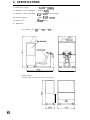
(6) Dimensions:
1 As installed:
35.5 (W) x 79.25 (D) x 79 (H) in
2 When divided:
Projector unit: 35.5 (W) x 28.75 (D) x 66.5 (H) in
6
Stand
23
Assy:
(W) x 50.5 (D) x 43 (H) in
23
7
Signboard
(7)
Assy:
35.5 (W)
x 19 (D) x 12.25 (H) in
Weight:
I As installed:
,
180kg
2 When divided
Rear cabinet
l
Assy:
Marquee Assy:
+ Monitor Cab Assy:
Gun stand Amy:
14Okg
6kg
125kg
40kg
7
3. CHECKING THE PACKAGE CONTENTS
The product package contains the following parts when shipped.
m
e Make sure that all the parts shown below are included in the product
package.
l
If any parts are missing, contact your distributor.
Marquee Assy (not shown)
Monitor Cabinet As
on coin
9,10,11,12
(cash box Interior)
8
No. 1
Name
Scecification
916 - 18 x I-IQ”, Socket Hd, Hex, Blk
9
4. OVERALL CONSTRUCTION
(components and their names)
___- __---- --- RearcabinetAq --___ ------------7
I
I
I
I
I
I
I
I
I
I
I
I
I
I
I
I
I
I
I
I
l Monitor Cabinet ASY
I
I
I
I
___-_---
I
:
Gun Tower Assy
I--__
I
I
I - - - - - - - - - - - - - - - - - _ _ - _ _ _ _ _ _ - - - - -
l
I
I
I
I
I
I
I
I
I
I
I
I
I
I
I
I
I__________---------_-------------------
IO
I
1
I
I
I
I
I
I
I
I
I
I
I
I
I
I
II
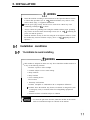
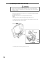
5. INSTALLATION
I A
! WARNING
l
Install the machine according to the instructions in this Operation Manual. Failure
to follow these procedures (see P. 11 “5. INSTALLATION”) may result in a fire,
electric shock, injury, or equipment malfunction.
* Insert the power plug securely into the service outlet. Poor contact may cause
overheating, resulting in a fire or bums.
l
l
5-I
Always connect the grounding lead. Using the machine without proper grounding
may result in an electric shock when leakage occurs. (See P. 18 “5-4 Connecting the
power cord and the ground”.)
Install the machine securely on the floor using the level adjusters. Failure to secure
the machine may result in accidents or injury. (See P. 17 “5-3-2 Adjusting the level
adjusters”.)
Installation conditions
n
5-l -1 1 Locations to avoid installing
! WARNING
This machine is designed for indoor use only. Never install the machine outdoors or
in any of the following locations:
. Locations exposed to direct sunlight
l
l
l
l
Locations subject to rain or water leakage
Damp locations
Dusty locations
Close to heating devices
. Hot locations
l
Extremely cold locations
. Locations susceptible to condensation due to temperature differences
9 Locations where the machine may become an obstacle in emergencies (such
as emergency exits), or locations where fire-extinguishing equipment is
installed
l
Unstable locations or locations subject to vibration
l
To secure the gun sensor detection, install the machine in the location
where no incandescent lamps are reflected on the monitor.
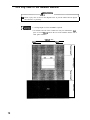
5-l-2 Play zone of the installed machine
! WARNING -I
,------ A
Q
Ensure a play zone as show in the diagram below to prevent contact between players
and observers or pessersby.
mm
l
l
A ceiling height of at least 2m 20cm is required.
To facilitate removal of the Control base Assy for maintenance, Ia%
space of at least 50cm between the rear of the machine and the wall or
other game machines.
1 m8Ocm or more
50cm o r m o r e
12
50cm or more
5-2
Required dimensions of carry-in passage (e.g.
doors and corridors)
e
Machine (excluding the POP panel)
780 (W) x 890 (D) x 1,870 (H) mm Weight: 150kg
The cany-in passage must be large enough to allow access.
Depending on the size of the access door, the machine can be further disassembled into
two Assy’s as shown below.
.
Signboard Assy (excluding the POP panels)
740 (W) x 180 (D) x 100 (H) mm Weight: 5kg
. Cabinet Assy
780 (W) x 890 (D) x 1,780 (H) mm Weight: 145kg
13
This page intentionally left blank.
14
This page intentionally left blank.
15
This page intentionally left blank.
16
5-3 Assembly
5-3-l Adjusting the level adjusters
Lower the level adjusters (2 locations) on the Cabinet Assy, and adjust the height so
that the casters are approximately 5mm above the floor.
- Floor
Lekl adjuster
r
”
“I
k/
1
Caster
17
SJNSTAUATION
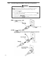
5-3-2 Installing and connecting the Gun stand Assy and
Rear cabinet Assy
-To be conducted by a techniclan Attach the
brackets to the
four socket screws
left- and right-band sides of the Gun stand
(5/18-18X
Assy using the
i-1/2)
18a
5.INSTALLATION
Move the Gun stand Assy close to the Rear cabinet Assy, and connect the two
connectors.
Attach the brackets on the Gun stand Assy to the Rear cabinet Assy using the four
socket screws (5116-l 6 x 2”)
Rear cabinet Assy
II
/-\4
18b
5-4
Connecting the power cord and the ground
A! WARNING
*
The ground lead must be connected using one of the methods below. Failure to
connect the ground lead may result in an electric shock if leakage occurs.
(1) Ground using a j-pin plug.
(2) If a 3-pin plug cannot be used, ground by connecting the ground lead of the 3-pinto-2-pin plug to the ground terminal.
(3) If neither 3-pin nor 3-pin-to-2-pin plug can be used. ground by connecting the
ground lead to the ground tetminal on the machine.
(l)With a 3-pin service outlet
Simply insert the power plug.
Power,plug
Win
(2) With a a-pin service outlet
the ground terminal.
Z-pin service 0
19
service outlet
6. MOVING AND TRANSPORTING
I
6-1
! WARNING PI
.A
.
Do not leave the machine on a slope, otherwise the machine may topple or cause
unforeseen accidents.
Moving (on the floor)
. Even when moving short distances, always raise the level adjusters
fully. (See P. 17 “5-3-2 Adjusting the level adjusters”.)
l
The machine height is approximately 2200mm (with the POP panels
(F) and (R) attached). Check the heights of access doors before moving. Remove the POP panels (F) and (R) if necessary. (See P. 14 “521 Dividing the Signboard Assy and the Cabinet Assy”.)
. Handle with care to prevent damage to the machine.
l
20
Be careful not to drop the Gun Assy.
6-2
Transporting
6-2-l Manual transport (carrying up or down stairs, etc.)
A! WARNING
.
Always divide into the Signboard Assy and the Cabinet Assy before conducting
manual carrying. (See. P 14 “5-2-l Dividing the Signboard Assy and the Cabinet
Assy”.) Attempting to carry the machine without dismantling it may cause unforeseen accidents.
Manual carrying must always be conducted by the appropriate number of people
specified below. Attempting to carry components with insufficient number of
people may result in accidents or injury.
6 people or more
. Cabinet Assy (145kg):
l
Cabinet Assy
. Do not subject components to shock when lowering to the ground.
. Always raise the level adjusters fully. (See P. 17 “5-3-2 Adjusting the
level adjusters”.)
l Be careful not to drop the Gun Assy
21
6-2-2 Loading on or unloading from a vehicle
A! WARNING
.
When using a forklift to move or transport the machine, always lift it at the positions marked with forklift stickers. Failure to do so may result in toppling or unforeseen accidents.
Always divide into the Signboard Assy and the Cabinet Assy before conducting
manual carrying. (See. P 14 “5-Z-l Dividing the Signboard Assy and the Cabinet
Assy”.) Attempting to carry the machine without dismantling it may cause unforeseen accidents.
c Manual carrying must always be conducted by the appropriate number of people
specified below. Attempting to carry components with insufficient number of
people may result in accidents or injury.
l
l
Cabinet Assy (145kg):
6 people or more
Cabinet Assy
. Handle with care to prevent damage to the machine.
l Always raise the level adjusters fully. (See P. 17 “5-3-2 Adjusting the
level adjusters”.)
. Do not subject components to shock when lowering to the ground.
l
22
Be careful not to drop the Gun Assy.
6-2-3 Trucking
I A! WARNING
l
When transporting the machine on a vehicle, secure the machine to prevent it from
moving due to acceleration or deceleration of the vehicle in transit. Failure to secure
the machine may result in accidents.
. Handle with care to prevent damage to the machine.
l
Remove the POP panels to prevent damage due to wind pressure. (See.
P 14 “5-2-l Dividing the Signboard Assy and the Cabinet Assy”.)
. When roping the machine, observe the following:
l
Always attach mpes in the positions indicated in the figure below.
* Insert pads of polystyrene foam or similar material between the
machine and the side panels of the truck to protect the machine
surfaces.
l
Secure the Gun Assy using cords, etc.
0 Secure the Gun Assy using cords, etc.
Protective cover (fabric or foam)
\
Polystyrene foam pad
Protective cover (fabric or foam)
23
7. OPERATION
.
.
l
Should a problem occur, switch OFF the power immediately and stop operating the
machine. Then, unplug the power cord from the service outlet. Operating the machine without correcting the problem may cause a fire or accident.
Dust accumulated on the power plug may cause a tire. Check the plug regularly and
remove any dust.
Insert the power plug securely into the service outlet. Poor contact may cause
overheating~ resdtir3g in %e oi bums.
.
Before operating the machine, always check that the machine has been installed
according to the instructions and procedures in this Operation Manual (see P. 11 “5.
INSTALLATION”). Failure to install correctly may result in a fire, electric shock,
injury, or equipment malfunction.
*
The warning labels describe important safety precautions. Observe the points below.
a To make sure that the warning labels attached to the machine are easily
legible, install the machine in a well-lit location, and keep the labels clean at
all times. Also make sure that the labels are not behind other game machines.
l Do not remove or alter the warning labels.
l
If the warning labels become dirty or damaged, replace with new labels. To
order replacement warning labels, contact your distributor.
7-I
Pre-service checks
Check the items described below before commencing operation.
If there are any problems, take appropriate action by referring to P. 43 “8-2 Troubleshooting”.
7-l -1 Safety checks
.
Check the points listed before operating the machine. These checks are necessary
for safe machine operation.
* Are the warning labels legible? (See P. 3 “l-4 Explanation of warning labels
attached to the machine”.)
l
Are all the level adjusters adjusted? (See P.17 “5-3-2 Adjusting the level
adjusters”.)
. Is there sufftcient play zone around the machine? (See P. I 1 “5-l Installation
conditions”.)
. Are both ends of the gun tube secured? Is there any damage to the gun tube?
l
Are the gun screws tightened?
7-1-2 Operation checks
. Turn ON the power switch, and check the following items. (See P. 27 “7-3-l Turning
ON the power switch”.)
(1) Check the sound. (Is there sound from the speakers?)
(2) Check the fluorescent lamps. (Do the Signboard Assy lamps light?)
(3) Check the picture. (Does the monitor display pictures normally?)
l
To check the following items, press the service switch and play the game. (See P. 27
“7-3-2 Adjustment switches”.)
(4) Check the gun operation, and set the gun sight. (See P. 33 “7-4-4
(b) GUN INI-
TIALIZE”.)
(5) Check the start switch operation.
25
7-2 Play instructions
l
The machine is a gun shooting game machine, which can be played by single player
or by two players.
* Insert the necessary number of coins to fill the credits. After the credits are tilled,
press the start button to start the game play.
* When the game play is started, try to shoot enemies on the screen.
a Up to eight bullets can be shot consecutively out of the player’s gun.
l
When bullets are run out, pull the trigger with the gun pointed outside the screen to
replenish the gun with bullets.
* First-aid kits and bonus items (“maneki-neko”: the beckoning figure of a cat displayed in shops to bring luck) sometimes appear during the game. Shoot a first-aid
kit to restore the playefs life. Shoot a bonus item to add the bonus score.
* Boss characters appear on some stages. These stages can be cleared by shooting the
boss characters.
. When playing alone, one more player can join in the game midway on the vacant
side by tilling the credits.
l
The player’s life is reduced when attacked by enemies. When it is gone, the machine
is ready to accept a continue play.
e The game is over if the player takes no actions before the entry time for a continue
play runs out.
e The player can enter his/her name if the final score is one of the ten best scores of the
day. The ten best scores of the day are the ten best scores from when the power is
turned ON to when it is turned OFF. Turning OFF the power clears the ten best
players and their scores, and returns to the default settings.
l
The ten best players are displayed as “THE BEST PLAYERS OF THE DAY” on the
ranking screen in attract mode.
. The top 3 players and their scores so far are not cleared even after the power is
turned OFF. For the procedures to clear the top 3 players and their scores so far,
read P. 31 “74-3 Setting the game options (GAME OPTIONS)“.
. The top 3 players so far are displayed as “TOP 3 PLAYERS”.
26
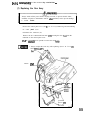
7-3 Adjustment
7-3-l Turning ON the power switch
After installing the machine as described on P. I I “5. INSTALLATION”, turn ON
the power switch of the machine.
Cord box Assy
Power switch
c
27
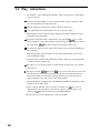
7-3-2 Adjustment switches
Open the service door of the Coin Assy to find the adjustment switches,
(a)Service
switch
Press this switch to increase the credit count without activating the coin counter.
(b) Test switch
Use this switch to switch test/attract mode. The machine enters attract mode when
the power is turned on, and press this switch to enter test mode.
Test mode allows the game pricing and other parameters to be changed, and various
parts to be tested.
(c)Select
switch
Flick this switch up or down to select an option in test mode
(4 Enter switch
After selecting options with the select switch, press this switch to finalize and
execute the selected option.
m
28
0 The service switches may not always operate unless pressed slowly
and positively.
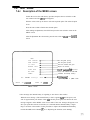
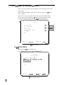
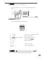
7-4 Test mode
7-4-l
Description of the MENU screen
Unlock the service door with the key provided, and press the test switch to set the
test mode to ON. The MENU screen appears.
Flick the select switch up or down to select the required option. The selected option
blinks.
Press the enter switch to finalize the selected option.
After making an adjustment, select EXIT and press the enter switch to return to the
MENU screen.
After all adjustments have been made, press the test switch to return to the GAME
screen.
MENU
COIN OPTIONS
Sets the game pricing.
GAME OPTIONS
Sets the game options.
Tests the switches and guns.
I/O TEST
MONITOR
The
SELECT
Adjusts the monitor.
TEST
SOUND TEST
Adjusls t h e sound vdume from t h e s p e a k e r s .
ADS DATA
D i s p l a y s and initializes the ADS data.
OTHERS
Initializes the backup memory.
internal
SW :CHOOSE
battery's
ENTER
dead.
Appears only when a problem occurs
--I---Error message'
SW :ENTER
MENU screen
* Error message (the internal battery is beginning to run down or has trouble)
When the error message (“The internal battery’s dead.“) appears, turn OFF the power, and
wait for approximately ten minutes. Then, turn ON the power again, and check if the error
message reappears on the MENU screen in test mode. If the error message still appears even
after you repeat these actions several times, it is assumed that the internal battery is beginning to run down or has trouble. For the procedures to replace the NAOMI internal battery.
read the NAOMI Service Manual (P, 10 “8. Replacing the batteries (main board)“).
7-4-2 Setting the game pricing and free play
(COIN OPTIONS)
This screen is used to set the game pricing and free play.
Select COIN OPTIONS on the MENU screen, and press the enter switch. The COIN
OPTIONS screen appears.
Use the select switch to select the option to be changed. The selected option blinks.
Press the enter switch to finalize the option to be changed.
After finalizing the option to be changed, change the option details using the select
switch.
After changing the option details, press the enter switch to return to the option
selection screen.
Select EXIT and press the enter switch to return to the MENU screen.
(CaW))
-
r
COIN OPTIONS
[DEFAULT IN GREEN]
GAME COST
CONTINUE COST
FREE PLAY
2 COIN (3 1 CREDIT f1 COIN IS) 1 CREDIT fOFF
EXIT
SELECT SW
:CAOOSE
COIN
OPTIONS
ENTER SW
:ENTER
screen
Option
Description
Default
Number of coins required
for one game play 1 to 9
coins
4
(b) Game pricing setting for the continued Number of coins required
play * 1
for the continued play 1 to
4
(a) Game pricing setting
:c) Free play setting *2
I
OFF (No)
ON (Yes)
OFF
I
COIN OPTIONS setting table
* 1 The game continue pricing cannot be set higher than the regular game
pricing.
To raise the game pricing and the game continue pricing, set the game
pricing tirst.
*2 When the free play setting is set to ON, the game starts just by pressing the
start button without having to insert any coins.
30
7-4-3 Setting the game options (GAME OPTIONS)
This screen is used to set the game options.
Select GAME OPTIONS on the MENU screen, and press the enter switch. The
GAME OPTIONS screen appears.
Use the select switch to select the option to be changed. The selected option blinks.
Press the enter switch to finalize the option to be changed.
After finalizing the option to be changed, change the option details using the select
switch.
After changing the option details, press the enter switch to return to the option
selection screen.
Select EXIT and press the enter switch to return to the MENU screen.
GAME
[DEFAULT
GAME DIFFICULTY
OPTIONS
IN GREEN]
C(MEDIUM)
(a)
OFFICIAL RANKING MESSAGE ON
lb)
HI-SCORE INITIALIZE
Cc)
EXIT
SELECT SW :CHOOSE
GAME
Option
ENTER SW :ENTER
OPTIONS
screen
Description
Default
A (VERY EASY)
(a) Game difficulty setting * 1
i rmzyM)
C(MEDIUM;
E (VERY HARD)
(c)Internet ranking display
ON (displayed)
when it is active *2
OFF (not displayed)]
NO (not initialized)
(b)High score initialization *3 YEs (Initialized)
ON
NO
GAME OPTIONS setting table
* 1 The game difficulty is adjusted according to the degree of the player’s life
(power).reduction.
*2 Setting (b) to OFF disables the notice and password display when the
Internet ranking is active. If the game difficulty (a) is changed from the
default setting to any of the other settings, (b) is automatically set to OFF
and cannot be changed. Changing the (b) setting is allowed only if the game
difticulty is set to default. The password is displayed only when playing
alone. It is disabled and erased from the screen when another player joins in
the game midway.
*3 To initialize the high score, select the (c) option and press the enter switch.
When YES and NO are displayed on the screen, select YES and press the
enter switch to start initialization.
31
7-4-4 I/O tests for switches (l/O TEST)
This screen is used to test the input and output of each switch and to check and set
the gun sight.
Select I/O test on the MENU screen, and press the enter switch. The I/O TEST
screen appears
Use the select switch to select the desired option. The selected option blinks.
Press the enter switch to display the UO TEST screen for the option selected.
Select EXIT and press the enter switch to return to the MENU screen.
I
I/O TEST
- (a)
- (b)
- (4
~ (4
I/O PCB CHECK
GUN
INITIALIZE
SWITCH
TEST
LAMP & RECOIL TEST
EXIT
(
SELECT
SW
:CHOOSE
I/O
ENTER
SW
:ENTER
TEST screen
(a) l/O PCB CHECK
This displays the I/O PCB CHECK screen.
Press the enter switch to return to the I/OTEST
screen.
I/O TEST
I/O PCB CHECK
I/O PCB : Connect OK
namco
ltd.;JYU-PCB;Verl.OO:JPN,
2Coins
2Guns
EXIT
SELECT
L
SW
-CHOOSE
ENTEF I
d
I/O PCB CHECK screen
32
SW .ENTER
I
(b) GUN INITIALIZE
This sets the gun sight. Check the gun sight regularly on this screen.
Select GUN INITIALIZE on the L’O TEST screen, and press the enter switch. The
GUN INITIALIZE MENU screen appears.
Use the select switch to select the desired option. The selected option blinks.
Press the enter switch to display the TEST screen for the option selected.
nJ‘at%L
. ..r-I-YTT
____ AL.._A^_ ~WIICII
_... :r-L LV
&^ .FLUL,,
_^A.._ +,.L” +I...
ciu1 ,-->
‘Al,” -prsss
,,,c 511,C‘
LIIC. \“Cb”T
IIILL.”
r^mn..
JcIccII.-
I/O TEST
GUN INITIALIZE MENU
GUN
GUN
INITIALIZE (1P)
INITIALIZE (2P)
EXIT
,
SELECT
SW :CHOOSE
ENTER
SW :ENTER
GUN INITIALIZE MENU screen
I
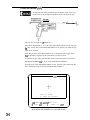
1 GUN INITIALIZE (1P)
l
To adjust the gun sight, position the gun so that the center of the cross
on the screen is on the sight line as shown below, and shoot the gun.
Sight line
_______
---------I__
This sets the gun sight for 1P (theplayer 1).
Select GUN INITIALIZE (1 P) on the GUN INITIALIZE MENU screen, and press
the enter switch. The GUN INITIALIZE MENU screen appears, on which the gun
sight can be checked.
Shoot the gun at the GUN INITIALIZE screen 1, and pull the gun trigger. Check
that the gunshot is displayed on the point which you tried to aim at.
To initialize the gun sight, press the enter switch (or the start button) on the GUN
INITIALIZE SCREEN Ito go to the GUN INITIALIZE SCREEN 2.
To return to the GUN INITIALIZE MENU screen, press the enter switch with the
select switch flicked up on the GUN INITIALIZE SCREEN 1.
GUN
SHOOT
INITIALIZE
AT
(1P)
SCREEN
TO CHECK GUN ACCURACY
?SH ENTER
P SELECT
SW:ADJUST
SW
+
GUN SIGHT
ENTER
SW
:EXIT
GUN INITIALIZE SCREEN 1 (for gun sight check)
34
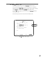
On the GUN INITIALIZE SCREEN 2, aim at the center of the cross on the upper
left comer of the screen, and pull the gun trigger. Then, aim at the center of the
cross on the lower right comer of the screen, and pull the gun trigger. The gun sight
is set (initialized).
After shooting the center of the cross on the lower right comer of the screen, the
GUN INITIALIZE SCREEN I reappears. Check that the gun can be shot at any
point within the frame.
If the gun sight is not set properly, press the enter switch (or the start button) to
return to the GUN INITIALIZE SCREEN 2, and try to set (initialize) the gun sight
again.
Y
GUN
INITIALIZE
(1P)
‘+
AIM AT CENTER OF THE CROSS
AND PULL GUN TRIGGER
After shwting the gun...
GUN
INITIALIZE
(1P)
AIM AT CENTER OF THE CROSS
AND PULL GUN TRIGGER
GUN INITIALIZE SCREEN 2 (for gun sight initialization)
* Press the test switch to return to the GAME screen.
35
2 GUN INlTlAblZE (2P)
l
This sets the gun sight for 2P (the player 2). The procedures are the same as described in 1
(c) SWITCH TEST
This tests the input and output of all the switches.
Press the enter switch with the select switch flicked up. The I/O TEST screen
reappears.
I/O TEST
SWITCH
TEST
[ON:REDl
COIN
000
SERVICE
OFF
TEST
OFF
SELECT(UP/DOWN)
OFF/OFF
ENTER
OFF
4
W
START BUTTON
OFF
4
(9
START BUTTON(2P)
OFF
4
(9)
GUN TRIGGER(lP)
OFF
4
04
GUN TRIGGER(2P)
OFF
UP SELECT SW
ENTER
4
4
(4
(W
(cl
(d)
0)
SW
:EXIT
SWITCH TEST screen
(a) The coin counter increments each time the coin switch is activated.
(b) ON appears when the service switch is pressed.
(c) The GAME screen reappears when the test switch is pressed.
(d) ON appears on the left (display: ON/OFF) when the select switch is in the up
position and on the right (display: OFF/ON) when the select switch is in the down
position.
(e) ON appears when the enter switch is pressed.
(t) ON appears when the start button (1P) is pressed.
(g) ON appears when the start button (2P) is pressed.
(h) ON appears when the gun trigger (1P) is pulled.
(i) ON appears when the gun trigger (2P) is pulled.
36
(d) LAMP & RECOIL TEST
This tests the start button lamps and the gun blowback mechanism (recoil).
The start button lamps are turned on as soon as the following screen is displayed.
Setting the parameters $@ and $A to OFF turns off the respective lamps. The lamps
are also turned off by exiting from the LAM? & RECOIL TEST screen.
Pull either 1P or 2P gun trigger on the screen to activate the blowback mechanism
for the respective gun.
Select EXIT and press the enter switch to return to the MENU screen.
r
\
I/O TEST
LAMP & RECOIL TEST
LAMP
TEST
START
BUTTON
LAMP
ON
START
BUTTON(2P)
LAMP
ON
RECOIL
4
t
13
Q
TEST
PULL BOTH GUN'S TRIGGERS
TO CONFIRM ACTION.
EXIT
,
SELECT
.
SW
:CHOOSE
ENTER
SW :ENTER
j
LAMP & RECOIL TEST screen
37
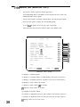
7-4-5 Monitor test (MONITOR TEST)
This screen is used to adjust the monitor parameters.
Select MONITOR TEST on the MENU screen, and press the enter switch. The
MONITOR TEST screen appears.
Use the select switch to select the required option. The selected option blinks,
Press the enter switch to display the corresponding pattern.
To exit from the pattern screen, press the enter switch again.
Select EXIT and press the enter switch to return to the MENU screen.
MONITOR
GRADATION
PATTERN
CROSSHATCH
PATTERN
CROSSHATCH
PATTERN
WHITE
WINDOW
[H)
WHITE
WINDOW
iM)
WHITE
WINDOW
CL)
INTERLACE
TEST
(CRT)
(PROJECTOR)
PATTERN
VIEW ANGLE ADJUST (CRT)
VIEH
ANGLE
FULL
WHITE
ADJUST
(PROJECTOR)
-
EXIT
SELECT
SW
:CHOOSE
MONITOR
ENTER
TEST
SW :ENTER
screen
(a) Displays a gradation pattern.
(b) Displays a crosshatch pattern for CRT monitors. (Not used for projectors.)
(c) Displays a crosshatch pattern for projectors. (Not used for CRT monitors.)
(d) Displays a white window (H or light)
(e) Displays a white window (M or medium).
(t) Displays a white window (L or dark).
(g) Displays an interlace pattern.
(h) Displays an adjustment screen for CRT monitors. (Not used for projectors.)
(i) Displays an adjustment screen for projectors. (Not used for CRT monitors.),
(j) Displays white over the entire screen.
38
(a)
(W
03
(4
(4
(0
(9)
(h)
(0
(i)
7-4-6 Sound test (SOUND TEST)
This screen is used to adjust the sound volume and check the stereo offset.
Select SOUND TEST on the MENU screen, and press the enter switch. The
SOUND TEST screen appears.
Use the select switch to select the option to be changed. The selected option blinks.
Select options (a), (b) or (c), and press the enter switch. The value for the selected
item blinks. Flick the select switch up or down to adjust the values.
When (c) is selected, the digit to be adjusted changes each time the enter switch is
pressed. Flick the select switch up or down to adjust each digit and set the desired
number. Press the service switch to play the selected music or sound effect.
* “000” is for no sound, and “001” is for stereo testing. Select “001” and press
the service switch to play the sound Corn the left-hand speaker, right-hand
speaker, and both speakers in sequence.
Select EXIT and press the enter switch to return to the MENU screen.
r
SOUND TEST
[DEFAULT IN GREEN1
VOLUME. ALL SP.
(O-127).
.
ATTRACT .(O-127).
080
064
+
+
REQUEST'SONG NO..*
MESSAGE.*******'**
000
+
+
-
(4
(b)
Cc)
Cd)
EXIT
SELECT
SW
SERVICESW
:CHOOSE
ENTER
:REQUEST
ON/OFF
SW
:ENTER
SOUND TEST screen
Option
Description
(a)Game sound volume setting 000 (minimum)
- 127 (maximum)
000 (minimum)
(b) Attract sound volume
- 127 (maximum)
setting
(c) Request
Music/sound effects selection
(d)Message
Displays the song code selected
by REQUEST.
SOUND TEST setting table
Default
080
064
000
7-4-7 Displaying and initializing game data (ADS DATA)
This screen displays the game data.
Select ADS DATA on the MENU screen, and press the enter switch. The ADS
DATA screen appears.
The game data is retained even when the power is switched off, unless ADS MITIALJZE or BACKUP MEMORY INITIALIZE on the OTHERS screen is executed.
Once the data has been confirmed, select EXIT and press the enter switch to return
to the MENU screen.
40
7-4-8 Miscellaneous (OTHERS)
This screen is used to initialize the backup memory.
Select OTHERS on the MENU screen, and press the enter switch. The OTHERS
screen appears.
Use the select switch to select the required option. The selected option blinks.
Press the enter switch to execute the selected (blinking) option.
Select EXIT and press the enter switch to return to the MENU screen.
r
OTHERS
[DEFAULT
IN
ROM Ver.*00/09/20-WED.
--,- - ,--. ___,
CLOCK.
S/N*
OOOOOO-.
GREEN]
15:15:59
la)
--:--:--
P)
123456
(cl
LANGUAGE*JPN
PAUSE.
03
(e)
OFF
NAOMI TEST MODE
BACKUP
MEMORY
(1)
INITIALIZE
(9)
EXIT
SELECT
SW
:CHOOSE
ENTER
SW
:ENTER
I
OTHERS screen
(a) Displays the software version.
(b) Not used for this machine.
(c) Displays the PC board serial number.
(d) Selects the language used in the game attract sequence. Select from: English
(ENG), French (FRA), German (GER), and Spanish (SPA).
(e) Sets the screen freeze function.
With this set to ON, press the enter switch to freeze/release the screen, and flick
the select switch upward to advance frames.
* The sound is cut while this setting is at ON.
(f) Enters PC board test mode. (Not used during machine operation.)
(g) Initializes the backup memory.
Select the desired item and press the enter switch to display “YES” and NO”.
Select “YES” and press the enter switch to clear all the settings such as the gun
sight, the high score and other settings altered and to reset to the default settings.
* After BACKUP MEMORY INITIALIZE (g) is executed, check the gun
sight on the I/O TEST screen (see P. 32 “7-44 LiO tests for switches (I/O
TEST)“), and reset it if necessary.
41
8. MAINTENANCE
Before carrying out maintenance work (such as troubleshooting or repairs), always
turn off the power switch to protect service staff and other personnel from electric
8-1 Maintenance and inspection
l
Pre-service checks must be carried out every day. (See P. 25 “7-1 Preservice checks”.)
8-l-l Cleaning the lenses
l
l
42
Clean the gun lenses every day. Remove any dirt from the lenses using
clean, soft cloth.
Do not use any detergents and chemicals.
8-2
Troubleshooting
l
Always mm off the power first to protect service staff and other personnel from
electric shock, accidents and injury, and to prevent damage to electrical circuits.
mm~
a If a fatdt o~Xisi3,~firsi
netted.
check that all ihe conneciois are firi-irly con-
. Contact your distributor if none of the cases below applies to the
problem, or if the action listed does not appear to resolve the problem.
. Never attempt to check the NAOMI or game PC board for continuity
using a multi-meter or other tester as Namco Ltd. is responsible for
repair. The internal voltage of the tester may damage the IC chips.
. Do not perform circuitry inspection using the logic tester mentioned
on the NAOMI Service Manual. Do not solder buttons to wire harnesses.
s Be sure to pack components properly when sending for repair. When
sending the NAOMI or game PC board, especially, wrap them in
sponge or bubble-wrap, and pack in a corrugated cardboard box to
protect against shock.
No corrugated cardboard box is included in the product package.
8-2-1
General -To be conducted by a technician *
If a fault occurs, first check that all the connectors are firmly connected.
Symptom
Main cause
Action
The machine operation is unstable, or
the machine malfunctions.
The supply voltage is
outside the range from
l lo-12OV AC (or 220240V A
Disconnect any other large
capacity electrical devices
(such as air-conditionsers and
large ride machines) on the
same power line to secure the
specified supply voltage.
The machine turns
The circuit protector
off during operation, has tripped and turned
off the power.
Turn on the power again. If
the circuit protector trips
~~~rd~~~o~t~c~~~~~~~~he
tributor.
See page
-
Page 27
8-2-2 Signboard
ASSY -To be conducted by a technician Main cause
Action
See page
The connector is disReconnect the connector
connected.
securely.
The fluorescent lamp is Replace the fluorescent lamp.
1lamp does not light.
Page 15
Page 45
Page 45
8-2-3 Cabinet
ASSY -To be conducted by a technician -
Symptom
Main cause
I
Action
There is no sound
from the speakers.
The sound volume is
too low.
The monitor connector
The monitor does
not display a picture. is disconnected.
8-2-4
Control
Page 39
Reconnect the connector.
Page 62
The Rack Assy connector is disconnected.
Reconnect the connector.
Page 5 1
The NAOMI is defective.
Page 52
palle!
Replace the NAOMI.
ASSY -To be conducted by a technician Main cause
Symptom
Action
See page
The start switch does The connector is disnot work.
connected.
The start switch is
defective.
Reconnect the connector.
Page 48
Replace the start switch.
Page 54
The connector is disconnected.
Reconnect the connector
securely.
Replace the lamp.
Page 48
Page 54
The lamp is burnt out.
8-2-5 Gun
ASSY -To be conducted by a technician -
ISymptom
The blowback does
not operate.
There is a problem
in gunshot display.
I
Main
cause
1
Action
I See
we I
The connector is disconnected.
Reconnect the connectors
securelv.
Pages 55 and
58
The microswitch is
defective.
Replace the microswitch.
Page 59
The solenoid is worn.
Replace the solenoid.
The lens is dirty.
Clean the lens.
Page 58
Page 57
Reset the gun sight.
Page 33
The gun sight is not set
properly.
44
1 See page 1
Adjust the sound volume.
I
/
This page intentior
45
This page intentionally left blank.
46
This page intentionally left blank.
47
This page intentionally left blank.
48
This page intentionally left blank.
49
This page intentionally left blank.
50
This page intentionally left blank.
51
This page intentionally left blank.
52
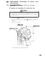
0-3
Disassembling, reassembling and replacing Assemblies and parts
8-3-l
COntrOi
panei
ASSY -To be conducted by a technlcian -
(1) Removing and reassembling the control panel cover
A WARNING
.
Always switch off the power before carrying out work, to prevent electric shock,
accidents or injuries to maintenance staff or other personnel, and to prevent damage
to electrical circuits.
Remove the guns from the gun holders.
Remove the eight Phillips truss screws (MS x 12), and then remove the control
panel cover.
Remove the two connectors.
Control panel mver
+)Phillips trussscrews
(+)Phillipstruss
(M5 x 12)
To reinstall, follow the removal procedure in reverse.
53
(2) Replacing the start switch and lamp
.
Always switch off the power before carrying out work, to prevent electric shock,
accidents or injuries to maintenance staff or other personnel, and to prevent damage
to electrical circuits.
Remove the control panel cover. (See P. 53 “S-3-3 (I) Removing and reassembling
the control panel cover”.)
Turn the control panel cover over, and pull out the start switch.
If the lamp is burnt out, remove the lamp and replace with a new one.
To replace the entire start switch, disconnect the fasten terminals, remove the start
switch, and replace with a new start switch.
Control panel awer underside
Fasten tkninal
To reinstall, follow the removal procedure in reverse.
54
U-J-Z
UUll ASSY
-To be conducted by a technician -
(1) Replacing the Gun Assy
l
Always switch off the power before carrying out work, to prevent electric shock,
accidents or injuries to maintenance staff or other personnel, and to prevent damage
to electrical circuits.
Remove the control panel cover. (See P. 53 “X-3-3 (I) Removing and reassembling
the
panel
control
cover”.)
Disconnect the connector (xl).
Remove the two countersunk head nuts (M6) securing the Gun Assy from the
underside of the control panel cover.
Pull the emnector cover upward to remove the Gun Assy.
l
Always readjust the Gun Assy after replacing. (See P. 36 “7-4-4 (b)
GUN lNITL4LlZE”J
Connector mver
ersunk head nti (MB)
Countersink
heed nut (M6)
,----r-.
Control panel underside
55
(2) Opening the gun slides
. Always turn off the power switch first to prevent damage to electrical
[ circuits.
Remove the four cap bolts (M3 x lo), the button bolt (M4 x 25), and the hexagon
cap nut (M4) to remove the gun slides (L) and (R).
Hexagon ypnti (M4)
Button bolt
Cap bolt (M3x IO)
Gun side (R)
To reinstall, follow the removal procedure in reverse.
56
(3) Opening the gun covers
Always turn off the power switch first to prevent damage to electrical
circuits.
l
m
Remove the gun slides (L) and (R). (See P. 56 “S-3-4 (2) Opening the gun slides”.)
With the gun cover (L) downwards, remove the four button bolts (M4 x lo), the
button bolt (M4 x 25), the four hexagon cap nuts (M4), and the cap bolt (M3 x 10)
to remove the gun cover (R). Be careful not to drop the lens.
Hexagon cap nut (M4)
Cap bail (M3 x 10)
Button boll (M4 x 10)
To reinstall, follow the removal procedure in reverse. Be sure that the lens is reinstalled with its spherical surface towards the muzzle.
. Be sure that the lens is reinstalled with
ispherical
surface towards the muzzle
57
(4) Replacing the solenoid
off the power switch first to prevent damage to electrical
Remove the gun slides and the gun covers. (See P. 56 “8-3-4 (2) Opening the gun
slides” and P. 57 “8-3-4 (3) Opening the gun covers”.)
Disconnect the connector on the solenoid.
Remove the cap bolt (M3 x 10) on the gun cover (L), and remove the solenoid
bracket.
Remove the cap screw (M) (M3 x 8), and detach the ground terminal.
Solenoid bracket
Connector
Ground terminal
Toothed lock washer
I
Cap screw (M) (M3 x 8)
Loose the nut (nominal diameter: 16) holding the solenoid in place, and pull out the
solenoid.
Remove the two cap screws (M) (M4 x 6), and remove the slide guide.
Pull out the solenoid plunger. Be careful not to lose the spring.
Nut (nominal diameter: 16)
Cap sc!ew (M) (M4 x 6)
uide
58
To reinstall, follow the removal procedure in reverse. Fit the D-shaped part of the
solenoid in the D-shaped hole of the solenoid bracket. Arrange the E-shaped snap
rings and the spacer in the correct order.
E-shaped snap ring
Plunger
Harness outlet (downwards)
(5) Replacing the microswitch
l
Always turn off the power switch first to prevent damage to electrical
circuits.
Remove the gun slide (R) and the gun cover (R). (See P. 56 “X-3-4 (2) Opening the
gun slides” and P. 57 “8-34 (3) Opening the gun covers”.)
Replace the microswitch.
Connect the b l u e harness.
Connect the black harness.
To reinstall, follow the removal procedure in reverse.
(6) Replacing the tube
I
*
Always turn off the power switch first to protect service staff and other personnel
from an electric shock, accidents and injury, and to prevent damage to electrical
circuits.
Remove the Gun Assy. (See P. 55 “8-3-4 (I) Replacing the Gun Assy”.)
Remove the two button bolts (M4 x IO), and remove the connector cover.
Remove the gun slides (L) and (R), and the gun cover (R). (See P. 56 “8-3-4 (2)
Opening the gun slides” and P. 57 “8-3-4 (3) Opening the gun covers”.)
Remove the solenoid bracket, and detach the connector and ground terminal on the
solenoid. (See P. 58 “8-3-4
(4) Replacing the solenoid”.)
Remove the connector t?om the sensor and the fastem terminal from the
microswitch.
Remove the button bolt (M4 x 10) holding the tube and the gun cover (L) in place to
remove the tube.
Fasten terminal (to microswitch)
Connsctor (to solenoid)
Connector (to sensor)
Connector cover
To reinstall, follow the removal procedure in reverse.
60
8-4
8-4-l
Replacing and adjusting the monitor
f?epklCiIlg
the
IllOllitOt’-To be conducted by a technician -
indicates “Do not touch”.
.
Always turn off the power switch first to protect service staff and other personnel
from an electric shock, accidents and injury, and to prevent damage to electrical
circuits.
.
The monitor interior contains components that generate high voltages of more than
20,OOOV. Do not touch the interior of the monitor, to prevent an electric shock.
o
Residual high voltage remains at the anode cap, anode lead, and fly-back transformer, even when the power has been switched off. Never touch, then to prevent an
electric shock.
.
When replacing the monitor, never touch any parts other than the stay, angle, and
monitor surface.
cap Approx. 29,WOV
Rear
Anode lead Approx. 29,000V
Focus lead Approx. 10,OOOV
Fly-back transformer
Approx. 29,000V
.
The monitor circuits are divided into primary and secondary circuits, which are
electrically insulated. Do not touch the primary circuit or both circuits simultaneously (short circuiting). This is extremely dangerous, and will result in an electric
shock or accidents.
/Secondary
circuit (chassis panels, CRT, etc.)
rimaty
.
.
.
Approx. 10,OOOV
circuit (main PCB)
If foreign material such as solder waste or paper fails inside the monitor, switch off
the power to prevent fire or breakdown, and contact your distributor.
If a fault occurs with the monitor, switch off the power immediately, and contact
your distributor.
The monitor weighs approximately 40kg. Work must be carried out by at least two
people.
61
This page intentionally left blank.
62
This page intentionally left blank.
63
8-4-2 Adjusting the monitor -To be conducted by a technician indicates “Do not touch”.
l
.
Monitor adjustment is carried out with the power switched on. There is therefore a
risk of an electric shock, accidents or injuries. Do not touch points other than those
specified in the adjustment procedures.
The monitor interior contains components that generate high voltages of more than
20,OOOV. Do not touch the interior of the monitor, to prevent an electric shock.
cap Approx. 29,OOOV
Rsar
Anode lead Approx. 29,000V
Focus lead Approx. 10,OOOV
Fly-back transformer
Approx. 29,OoOV
.
Approx. iO,OOOV
The monitor circuits are divided into primary and secondary circuits, which are
electrically insulated. Do not touch the primary circuit or both circuits simultaneously (short circuiting). This is extremely dangerous, and will result in an electric
shock or accidents.
/Secondary circuit (chassis panels, CRT, etc.)
rimary circuit (main PCS)
.
l
64
If foreign material such as solder waste or paper falls inside the monitor, switch off
the power to prevent fire or breakdown, and contact your distributor.
If a fault occurs with the monitor, switch off the power immediately, and contact
your distributor.
. The monitor is adjusted to the optimum conditions at the factory.
Adjustment is not normally necessary.
Remove the rear panel (See P. 47 “S-3-2 (I) Removing and reinstalling the rear
panel”.)
: wall,not as shown
Adjustmeni
functions
The monitor adjustment board is configured as below:
H PHASE
Adjusts the picture to the center of the raster.
V CENTER
Adjusts the vertical center.
HSIZE (Horizontal size adjustment)
Adjusts the horizontal picture size.
CONTRAST
Adjusts the picture contrast.
V HOLD
Adjusts the vertical hold.
DP
7
SIZE
Adjusts the picture size.
a
BRIGHT
Adjusts the picture brightness.
l
(a) - (c) cannot be adjusted without technical experience and messuring instruments. Do not touch. Note that if accidentally touched, it
may not be possible to return it to its original setting.
65
(b) Adjustment preparations
. The display position and size of the picture on the monitor will vary
depending on the direction of the machine when adjusted. Adjust the
machine in the installed position whenever possible. If the machine
has to be moved for adjustment, adjust the machine in the same
direction as when installed.
* If the machine installation position is changed tkequently, or when not
adjusting in the installed position, adjust with the monitor facing east.
Wait at least 30 minutes after switching the power ON before adjusting.
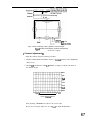
(c) Monitor display adjustment
Display the MONITOR TEST screen in test mode. (See P. 29 “74 Test mode”.)
< Adjusting display size >
Adjustment includes both “Display size adjustment” and “Contrast adjustment”.
Adjust the display size using the following procedure.
1. Display VIEW ANGLE ADJUST (CRT) (Figure 3: Picture size/display position
adjustment instruction diagram) on the MONITOR TEST screen. (See P. 38 “7-4-5
Monitor test (MONITOR TEST)“.)
2 . Align the center of the display position.
e Adjust both ” 4 H.POSI (Horizontal position)” and ” 6 V.POSI (Vertical
position)” alternately to bring the crosshair roughly in the center of the
screen.
3. Adjust the horizontal size and position.
l
l
Adjust ” 3 HSIZE (Horizontal size)” so that the green and white boundary of
the pattern roughly aligns with the edge of the screen at the center of the left
and right-hand edges of the screen.
Fine adjust 3 and 4 to bring the difference on either side to within 5mm.
4. Adjust the vertical size and position.
l
l
66
Adjust ” 5 V.SIZE {Vertical size)” so that the green and white boundary of the
pattern roughly aligns with the edge of the screen at the center of the top and
bottom edges of the screen.
Fine adjust 5 and 6 to bring the difference at the top and bottom to within
5mm.
outer edge of green window
O u t e r e d g e o f b&k cress-hatching
Figure 3 Picture size/display position adjustment instruction diagram
Figuce 3 Picture size/display position adjustment
instruction diagram
< Contrast adjustment >
Adjust the contrast using the following procedure.
1. Display GRADATION PATTERN (Figure 4: 16-shade pattern) on the MONITOR
TEST screen.
2. Adjust “$@ CONTRAST” and “$A BRIGHT” to display 16 shades with black as
the darkest section.
While
Cyan
I
Blue
Yellow
Green
Red
, Black
Light 4
l
Figure 4 16-shade
After adjusting, reinstall the
rear panel in
Dark
pattern
the reverse order.
Be sure to reset the gun sight. (See P. 33 “7-4-4
(b) GUN INITIALIZE”.)
67
This page intentionally left blank.
68
This page intentionally left blank.
IO. PARTS LIST
IO-1 Cabinet Assy
Q1
70
(OpposiJe
side)
* 1: Contact your distributor when placirig an order if a non-random item of No.33 is required.
*2: Repair service is available for the item No.38. Contact your distributor.
71
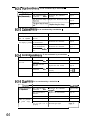
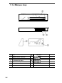
1 O-2 Marquee Assy
No. Part
72
NAI Part #
Qv
1
Marquee, Acrylic, Silkscreen
1
N140-0951
2
Marquee Box, Wood
1
Nl83-9526-00
l-00
3
Fluorescent lamp fixture
1
VG57-02025-00
4
Fluorescent lamp
1
VG57-02028-00
IO-3 Control panel Assy
Part
No.
1
Control Panel Cover
2
Decal,
3
Decal, Control Panel, Right
a’ty
NAI Part #I Mfg
Ref #
1
NIQO-09566-00
1
N1402547221200
1
Nl402547221201
4
Decal, Control Panel, Center
1
Nl40-0956740
5
Gun Tether Mounting Plate, Left
1
TS10-0766401
6
Gun Tether Mounting Plate, Right
1
TSI
7
Pushbutton, w/microswitch, 12V, Red, round
1
VGBO-09614-20
I Happ
54-0004-201
1
VGEO-09614-22
I Happ
54oow2zLSP
a
9
Control
Panel,
Pushbutton, w/microswitch,
Left
12V, Blue, round
Chain, 38 Link, #4, .12 Dia. Wire
2
700-290
O-07669-00
PBZO-03154-00
73
IO-4 Gun Assy
Part
No.
Q’ty
NAI Part #I Mfg #
Ref #
1
Gun cover (L, red)
1
PBO9-03430-00
296-411
2
Trigger spring
1
PBO9-296-421
296-421
3
Trigger (red)
1
PBO9-04836-00
296-415
4
Solenoid
1
PBO9-004-056
004-056
5
Gun cord harness Assy
1
PBO9-296-401
296-401
6
Connector
1
PB90-05447-00
296-424
7
Gun cover (R, red)
1
PBO9-03431-00
296-412
cover
75
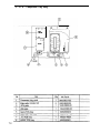
IO-5 Stand Assy
t
76
No.
Part
w
Type and ratings
Part No.
1
Stand
1
NM-09531 -00
700-330
2
Controt panel base
1
Nl63-09532-00
700331
3
Gun holder DX (Red)
1
Nl02547211300
790-332
4
Gun holder DX (Slue)
1
NI025472113.01
790-333
5
Maintenance cover
1
N163-09560-00
799-336
6
Bracket
2
Nl10-09561-00
700-337
7
Nut
2
Nl10-09562-00
700-336
6
Control panel bracket
2
NllO-09563-00
700-339
9
Control panel stay A
1
NIIO-09564-90
700-340
10
Control panel stay B
1
Nl102647212100
700341
11
Stand sticker
(LA)
1
Nl402547212200
700-342
12
Stand sticker (PA)
1
NM02547212201
790343
13
Stand sticker (LB)
1
NM02647212300
700-344
14
Stand sticker ( R B )
1
NM0254721
700-345
15
N o t i c e sticker
plate
(No
16
1 C a s t e r (fixed type)
17
Woofer speaker
16
1 Pipe duct
standing) EXP
1
2301
1
1 VG40-06765-09
1 4
) VG24-03191-00
I
102-202
I
1 VG64-07796-00
(
006-136
1
1 VG54-07630-00
1
461-175
006-l 16
77
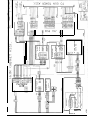
1 O-6 Component Tray Assy
78
AlddflS
AZI
tl3MOd
IB s
Lb---- -----------L3
II
L