1
To Purchase This Item, Visit BMI Gaming | www.bmigaming.com | (800) 746-2255 | +561.391.7200
DEADSTORM PIRATES
SPECIAL EDITION
OPERATION MANUAL
The actual product may differ slightly from the illustrations in this manual.
To ensure safe operation of the game machine, be sure to read this Operation Manual before use.
Keep this Operation Manual in a safe place for quick access whenever needed.
To Purchase This Item, Visit BMI Gaming | www.bmigaming.com | (800) 746-2255 | +561.391.7200
Important
Read PRECAUTIONS and INSTALLATION
Sections before operating game
FCC Notice
Note: This equipment has been tested and found to comply with the limits for a Class A
digital device, pursuant to Part 15 of the FCC Rules. These limits are designed to provide
reasonable protection against harmful interference when the equipment is operating in a
commercial environment. This equipment uses, and can radiate radio frequency energy
and, if not installed and used in accordance with the instruction manual, may cause
harmful interference to radio communications. Operation of this equipment in a residential
area is likely to cause harmful interference in which case the user will be required to
correct the interference at his own expense.
Copyright 2014 NAMCO AMERICA INC. - All rights reserved
No part of this publication may be reproduced by any mechanical photographic, or
electronic process, or in the form of a phonographic recording, nor may it be stored in a
retrieval system, transmitted, or otherwise copied for public or private use, without
permission from NAMCO AMERICA INC.
To Purchase This Item, Visit BMI Gaming | www.bmigaming.com | (800) 746-2255 | +561.391.7200
INTRODUCTION
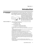
Thank you for purchasing the “DEAD STORM PIRATES SPECIAL EDITION” game machine (hereafter
referred to as the “machine”).
This operation manual describes:
How to install, operate, relocate, transport, maintain and discard of the machine safely and properly
How to operate the machine correctly and make full use of its features
How to ensure safety of players and bystanders
Inquiries regarding this machine and its repair
For further information about the machine and its repair, contact your distributor.
The software included in the machine is protected by copyright laws. The software must not
game machine. Violators of copyright laws may be subject to criminal penalties. Do not use
the storage media containing software in any other game machine; otherwise, machine malfunctions may result.
This machine uses the following licenses.
This software uses fonts produced by Fontworks Inc.
Fontworks, and font names are trademarks or registered trademarks of Fontworks Inc.
PolycomR G.722.1 Annex C audio coding technology
To Purchase This Item, Visit BMI Gaming | www.bmigaming.com | (800) 746-2255 | +561.391.7200
INTRODUCTION
This machine uses MXML.
MXML is used under the MIT License.
MXML License
Copyright (c) 2003 Matthew Riek
Permission is hereby granted, free of charge, to any person obtaining a copy of this software
tion, including without limitation the rights to use, copy, modify, merge, publish, distribute,
sublicense, and/or sell copies of the Software, and to permit persons to whom the Software
is furnished to do so, subject to the following conditions:
The above copyright notice and this permission notice shall be included in all copies or substantial portions of the Software.
THE SOFTWARE IS PROVIDED “AS IS”, WITHOUT WARRANTY OF ANY KIND, EXPRESSED OR IMPLIED, INCLUDING BUT NOT LIMITED TO THE WARRANTIES OF MERCHANTABILITY, FITNESS FOR A PARTICULAR PURPOSE AND NONINFRINGEMENT.
IN NO EVENT SHALL THE AUTHORS OR COPYRIGHT HOLDERS BE LIABLE FOR ANY
CLAIM, DAMAGES OR OTHER LIABILITY, WHETHER IN AN ACTION OF CONTRACT,
TORT OR OTHERWISE, ARISING FROM, OUT OF OR IN CONNECTION WITH THE
SOFTWARE OR THE USE OR OTHER DEALINGS IN THE SOFTWARE
Regarding the licenses and trademarks pertaining to SYS357 (Rack Assy) and SYS369
(Rack Assy), see http://www.bandainamcogames.co.jp/am/vg/s357-license/.
The names of systems and products that are used in the game machine or mentioned in this
operation manual but are not described in the above URL are generally trademarks or registered trademarks of their respective companies.
To Purchase This Item, Visit BMI Gaming | www.bmigaming.com | (800) 746-2255 | +561.391.7200
To Purchase This Item, Visit BMI Gaming | www.bmigaming.com | (800) 746-2255 | +561.391.7200
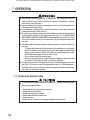
1. SAFETY PRECAUTIONS – Be sure to read these instructions to ensure safety –
Instructions to the owner
z If you entrust another party to perform installation, operation, relocation, transportation, maintenance or discarding of the machine, instruct the concerned party to read and observe all
the instructions and precautions in this operation manual regarding the particular action to be
taken.
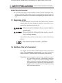
1-1 Magnitudes of risk
On the labels attached to the machine and in this operation manual, precautions
UHJDUGLQJ VDIHW\ DQG SURSHUW\ GDPDJH DUH FODVVL¿HG DV VKRZQ EHORZ LQ DFFRUGDQFHZLWKWKHPDJQLWXGHRIWKHSDUWLFXODUULVN
: Failure to avoid the indicated risk may result in death or
serious injury.
: Failure to avoid the indicated risk may result in minor injury or property damage.
1RWHVUHODWHGWRPDFKLQHIXQFWLRQVEXWQRWWRVDIHW\DUHPDUNHGZLWKWKHIROORZLQJ
indication.
: Note related to product function or protection.
'HÀQLWLRQRIWKHWHUP´WHFKQLFLDQµ
7KLV RSHUDWLRQ PDQXDO LV ZULWWHQ IRU DUFDGH SHUVRQQHO +RZHYHU WKH VHFWLRQV
marked “To be conducted by a technician only” in the table of contents are
ZULWWHQIRUWHFKQLFLDQV7KHVHWDVNVVKRXOGEHFRQGXFWHGE\WHFKQLFLDQVRQO\
Technician: A person engaged in machine design, manufacture, inspection or maintenance service for a manufacturer of amusement
HTXLSPHQWRUDSHUVRQZKRKDVWHFKQLFDONQRZOHGJHUHODWHGWR
electricity, electronics or mechanical engineering at a level equal
to or higher than that of a technical high school graduate and is
engaged routinely in the maintenance and management (including
repair) of amusement machines.
1
To Purchase This Item, Visit BMI Gaming | www.bmigaming.com | (800) 746-2255 | +561.391.7200
1. SAFETY PRECAUTIONS
1-3 Top-priority safety precautions
z 6KRXOGDQ\DEQRUPDOLW\RFFXUWXUQRIIWKHSRZHUVZLWFKLPPHGLDWHO\WRVWRSRSHUDWLQJWKHPDFKLQH7KHQXQSOXJWKHSRZHUFRUGSOXJIURPWKH$&RXWOHW2SHUDWLQJ
WKHPDFKLQHZLWKRXWFRUUHFWLQJDEQRUPDOLWLHVFDQUHVXOWLQDÀUHRUDFFLGHQW
z 6RPH PRQLWRU VHFWLRQV UHPDLQ KRW RU FKDUJHG ZLWK KLJK YROWDJH HYHQ DIWHU WKH
SRZHU VZLWFK LV WXUQHG RII 'R QRW WRXFK WKH PRQLWRU XQQHFHVVDULO\ LQ RUGHU WR
DYRLGHOHFWULFVKRFNDQGEXUQV
z 'XVWDFFXPXODWHGRQWKHSRZHUFRUGSOXJPD\FDXVHDÀUH&KHFNWKHSRZHUFRUG
SOXJUHJXODUO\DQGUHPRYHGXVW
z ,QVHUWWKHSRZHUFRUGSOXJÀUPO\LQWRWKH$&RXWOHW3RRUFRQWDFWPD\FDXVHRYHUKHDWLQJWKDWFDQOHDGWRDÀUHRUEXUQV
z $GDPDJHGSRZHUFRUGFDQFDXVHDÀUHHOHFWULFVKRFNRUHOHFWULFDOOHDNDJH2EVHUYHWKHIROORZLQJFDXWLRQV
.HHSWKHSRZHUFRUGDZD\IURPKHDWLQJGHYLFHV
Do not twist the power cord.
Do not bend the power cord forcibly.
Do not alter the power cord.
Do not bundle the power cord.
'RQRWSXOOWKHSRZHUFRUG$OZD\VXQSOXJE\KROGLQJWKHSRZHUFRUGSOXJ
DQGDYRLGSXOOLQJWKHSRZHUFRUG
Do not place anything on the power cord.
'RQRWJHWWKHSRZHUFRUGFDXJKWE\WKHPDFKLQHRWKHUHTXLSPHQWRUZDOO
'RQRWGRDQ\WKLQJHOVHWKDWPLJKWGDPDJHWKHSRZHUFRUG
z Do not wet the power cord or power cord plug with water. Water can cause an electric shock or electrical leakage.
z Do not touch the power cord plug with a wet hand. Doing so can result in an electric shock.
z 7KHPDFKLQH·VUDWHGSRZHUVXSSO\YROWDJHDQGPD[LPXPFRQVXPSWLRQFXUUHQWDUH
9$&DQG$UHVSHFWLYHO\7RSUHYHQWÀUHDQGHOHFWULFVKRFNEHVXUHWRXVH
LQWHULRUZLULQJWKDWFRQIRUPVWRWKHVHSRZHUVXSSO\VSHFLÀFDWLRQV
z 2SHUDWHWKHPDFKLQHZLWKDSRZHUVXSSO\YROWDJHLQWKHUDQJHRIWR9$&
2SHUDWLQJ WKH PDFKLQH ZLWK D VXSSO\ YROWDJH RXWVLGH WKH VSHFLILHG UDQJH PD\
FDXVH D ÀUH RU HOHFWULF VKRFN 7R HQVXUH WKDW WKH PDFKLQH RSHUDWHV LQ RSWLPXP
FRQGLWLRQPDLQWDLQWKHSRZHUVXSSO\DW9$&
z 7RHQVXUHVDIHRSHUDWLRQRIWKHPDFKLQHEHVXUHWRFRQGXFWWKHSUHVHUYLFHFKHFN
VHH3´3UHVHUYLFHFKHFNµDQGPDLQWHQDQFHVHH3´%0DLQWHQDQFHµ
GHVFULEHGLQWKLVPDQXDO)DLOXUHWRFRQGXFWWKHSUHVHUYLFHFKHFNRUPDLQWHQDQFH
FDQUHVXOWLQDQXQH[SHFWHGDFFLGHQW
z 8VH FRQVXPDEOHV DQG VHUYLFH SDUWV LQFOXGLQJ IDVWHQHUV VSHFLÀHG E\ RXU FRPSDQ\7RRUGHUSDUWVFRQWDFW\RXUGLVWULEXWRU
z 'RQRWFRQYHUWWKHPDFKLQHZLWKRXWSHUPLVVLRQ'RQRWSHUIRUPDQ\ZRUNWKDWLV
QRWGHVFULEHGLQWKLVRSHUDWLRQPDQXDO8QDXWKRUL]HGFRQYHUVLRQRIWKHPDFKLQH
PD\FUHDWHXQIRUHVHHQKD]DUGV
z :KHQWUDQVIHUULQJWKHRZQHUVKLSRIWKHPDFKLQHEHVXUHWRSURYLGHWKLVRSHUDWLRQ
PDQXDOWRJHWKHUZLWKWKHJDPHPDFKLQH
2
To Purchase This Item, Visit BMI Gaming | www.bmigaming.com | (800) 746-2255 | +561.391.7200
1. SAFETY PRECAUTIONS
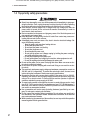
'HVFULSWLRQRIZDUQLQJODEHOVDWWDFKHGWRWKHPDFKLQH
z 7KHZDUQLQJODEHOVGHVFULEHLPSRUWDQWVDIHW\SUHFDXWLRQV%HVXUHWRREVHUYHWKH
following:
7RHQVXUHWKDWWKHZDUQLQJODEHOVDWWDFKHGWRWKHPDFKLQHDUHHDVLO\OHJLEOH
LQVWDOO WKH PDFKLQH DW DQ DSSURSULDWH ORFDWLRQ ZLWK DPSOH LOOXPLQDWLRQ DQG
NHHSWKHODEHOVFOHDQDWDOOWLPHV$OVRPDNHVXUHWKDWWKHODEHOVDUHQRWKLGGHQEHKLQGDQRWKHUJDPHPDFKLQHRURWKHUREMHFWV
'RQRWUHPRYHRUDOWHUWKHZDUQLQJODEHOV
,IWKHZDUQLQJODEHOVEHFRPHH[FHVVLYHO\GLUW\RUGDPDJHGUHSODFHWKHPZLWK
QHZODEHOV7RRUGHUZDUQLQJODEHOVFRQWDFW\RXUGLVWULEXWRU
Back side
3
To Purchase This Item, Visit BMI Gaming | www.bmigaming.com | (800) 746-2255 | +561.391.7200
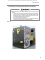
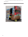
1. SAFETY PRECAUTIONS
Front side
4
To Purchase This Item, Visit BMI Gaming | www.bmigaming.com | (800) 746-2255 | +561.391.7200
CONTENTS
INTRODUCTION
1. SAFETY PRECAUTIONS - Be sure to read these instructions to ensure safety - .......................... 1
1-1
Magnitudes of risk .......................................................................................................................................... 1
'H¿QLWLRQRIWKHWHUP³WHFKQLFLDQ´................................................................................................................... 1
7RSSULRULW\VDIHW\SUHFDXWLRQV........................................................................................................................ 2
'HVFULSWLRQRIZDUQLQJODEHOVDWWDFKHGWRWKHPDFKLQH .................................................................................. 3
2. SPECIFICATIONS ................................................................................................................................... 8
3. CHECKING THE PACKAGE CONTENTS .............................................................................................. 9
4. OVERALL CONSTRUCTION (Names of Parts)....................................................................................11
5. INSTALLATION AND CARRY-IN PASSAGE CONDITIONS................................................................. 13
,QVWDOODWLRQFRQGLWLRQV ................................................................................................................................... 13
/RFDWLRQVWRDYRLG................................................................................................................................ 13
3OD\]RQHIRULQVWDOOHGPDFKLQH........................................................................................................... 14
5HTXLUHGGLPHQVLRQVRIFDUU\LQSDVVDJHVXFKDVGRRUVDQGFRUULGRUV..................................................... 15
6. MOVING AND TRANSPORTING .......................................................................................................... 16
0RYLQJRQWKHÀRRU..................................................................................................................................... 16
6-2 Transportation............................................................................................................................................... 17
7. OPERATION .......................................................................................................................................... 18
3HRSOHZKRVKRXOGQ
WSOD\ ............................................................................................................................ 18
6DIHW\SUHFDXWLRQVWREHREVHUYHGE\SOD\HUV.............................................................................................. 19
3UHVHUYLFHFKHFN ......................................................................................................................................... 20
6DIHW\FKHFNEHIRUHSRZHU21 ......................................................................................................... 20
2SHUDWLRQFKHFNDIWHUSRZHU21....................................................................................................... 21
+RZWRSOD\................................................................................................................................................... 22
%DVLFUXOHV .................................................................................................................................... 22
2SHUDWLQJPHWKRG ......................................................................................................................... 22
([SODQDWLRQRIWKHJDPHV\VWHP................................................................................................... 22
6WDUWEXWWRQ ................................................................................................................................... 23
([SODQDWLRQRIWKHSRZHUVZLWFKDQGDGMXVWPHQWVZLWFKHV........................................................................... 24
3RZHUVZLWFKORFDWLRQDQGWXUQLQJRQWKHVZLWFK ................................................................................. 24
$GMXVWPHQWVZLWFKHV............................................................................................................................ 25
7HVWPRGH ..................................................................................................................................................... 26
'HVFULSWLRQRIWKHPHQXVFUHHQ0(18............................................................................................. 26
*DPHIHHVHWWLQJ&2,1237,216.................................................................................................... 27
*DPHGHWDLOVHWWLQJ*$0(237,216............................................................................................... 28
5
To Purchase This Item, Visit BMI Gaming | www.bmigaming.com | (800) 746-2255 | +561.391.7200
CONTENTS
6ZLWFKVHQVRUWHVW,27(67 ............................................................................................................. 29
,23&%&+(&. ........................................................................................................................... 30
6:,7&+7(67.............................................................................................................................. 31
*817(67.................................................................................................................................... 32
*81&$/,%5$7,21 ..................................................................................................................... 33
67((5,1*7(67 ......................................................................................................................... 34
2873877(67 ............................................................................................................................. 35
0RQLWRUDGMXVWPHQW021,7257(67................................................................................................ 36
*$00$$'-867.......................................................................................................................... 37
6RXQGDGMXVWPHQW6281'7(67 ..................................................................................................... 38
*DPHGDWDGLVSOD\LQLWLDOL]DWLRQ%22..((3,1* ............................................................................. 39
,QLWLDOL]DWLRQDQGRWKHUV27+(56...................................................................................................... 40
+''&+(&.................................................................................................................................. 41
%$&.830(025<,1,7,$/,=( .................................................................................................. 42
&/2&.6(77,1*......................................................................................................................... 42
6RIWZDUHXSGDWH .................................................................................................................................. 44
(UURUGLVSOD\IRUWKHDUFDGHRSHUDWRU.......................................................................................................... 45
*XQ$VV\DGMXVWPHQWLQLWLDOL]DWLRQDIWHUSDUWVUHSODFHPHQW........................................................................ 47
,QLWLDOL]LQJWKHYROXPHVLQWKH*XQ$VV\V............................................................................................. 47
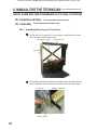
8. MANUAL FOR THE TECHNICIAN – To be conducted by a technician only – ............................... 48
8A. Assembly and Setup - To be conducted by a technician only - ..................................................... 48
$ $VVHPEO\7REHFRQGXFWHGE\DWHFKQLFLDQRQO\.................................................................................... 48
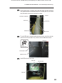
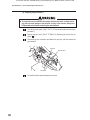
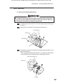
$$VVHPEOLQJ0RQLWRU$VV\DQG&RQWURO$VV\....................................................................................... 48
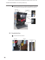
$$VVHPEOLQJ6HDW$VV\ ....................................................................................................................... 50
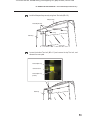
$$VVHPEOLQJ5RRI$VV\ ....................................................................................................................... 52
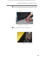
$$VVHPEOLQJ0DUTXHH$VV\................................................................................................................ 52
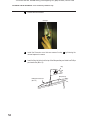
$$VVHPEOLQJ6LGHERG\/DQG6LGHERG\5 ...................................................................................... 55
$$GMXVWLQJOHYHODGMXVWHUV .................................................................................................................... 55
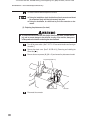
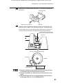
$&RQQHFWLQJWKHSRZHUFRUGDQGJURXQGOHDG.................................................................................... 56
8B. Maintenance – To be conducted by a technician only – ................................................................. 57
% ,QVSHFWLRQDQGPDLQWHQDQFH......................................................................................................................... 57
%,QVSHFWLRQLWHPV................................................................................................................................. 57
% 7URXEOHVKRRWLQJ ............................................................................................................................................ 58
%*HQHUDO.............................................................................................................................................. 59
%0RQLWRU$VV\ ..................................................................................................................................... 60
%*XQ$VV\ ........................................................................................................................................... 61
%:KHHO$VV\........................................................................................................................................ 61
%6HDW$VV\........................................................................................................................................... 61
%0DUTXHH$VV\.................................................................................................................................... 61
% (UURUGLVSOD\IRUWKHWHFKQLFLDQ................................................................................................................... 62
% 5HPRYLQJDQGLQVWDOOLQJ$VV\VDQGSDUWV ..................................................................................................... 63
%0RQLWRU$VV\ ...................................................................................................................................... 63
5HSODFLQJWKH5DFN$VV\ .............................................................................................................. 63
6
To Purchase This Item, Visit BMI Gaming | www.bmigaming.com | (800) 746-2255 | +561.391.7200
CONTENTS
...................................................................................................... 65
.............................................................................................. 66
........................................................................................................... 67
...................................................................................................................................... 70
...................................................................................................... 70
.............................................................................................. 71
........................................................................................................................................... 72
.......................................................................................... 72
..............................................................................................74
.............................................................................................77
............................................................................................................ 79
................................................................................................... 80
..................................................... 81
........................................................................................................... 83
...................................................................................................... 86
........................................................................................................ 88
........................................................................................................................................ 89
...................................................................................... 89
......................................................................................... 90
...................................................................................................................... 92
.................................................................................................................................... 93
................................................................................................... 93
............................................................................................................................... 95
................................................................ 95
........................................................................................... 97
.................................................................................................... 98
9. DISCARDING THE MACHINE............................................................................................................... 99
10. PARTS LISTS ...................................................................................................................................... 100
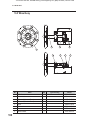
10-1 Monitor Assy............................................................................................................................................. 100
............................................................................................................................................. 102
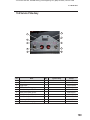
10-3 Seat Assy ................................................................................................................................................. 104
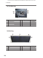
10-4 Gun Assy .................................................................................................................................................. 106
............................................................................................................................................... 108
.................................................................................................................................... 109
.......................................................................................................................................... 110
10-8 Roof Assy ................................................................................................................................................. 110
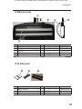
10-9 Marquee Assy............................................................................................................................................111
................................................................................................................................................111
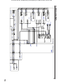
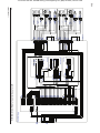
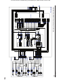
11. WIRING DIAGRAMS ............................................................................................................................112
7
To Purchase This Item, Visit BMI Gaming | www.bmigaming.com | (800) 746-2255 | +561.391.7200
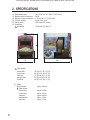
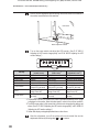
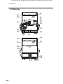
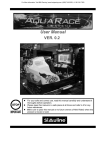
2. SPECIFICATIONS
Rated power supply
Maximum power consumption
Maximum current consumption
Coin box capacity
Display device
Dimensions
1 As installed
120 ± 5 VAC (60 Hz) / 230V ± 5 VAC (50 Hz)
600 W
5 A (120 VAC) / 2.5 A (230 VAC)
Approx. 3,000 coins
LCD monitor (55” screen)
70”(W) x 98” (D) x 89” (H)
89"
(1)
(2)
(3)
(4)
(5)
(6)
70"
2
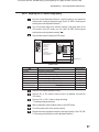
When divided
Monitor Assy
Control Assy
Seat Assy
Marquee Assy
Roof Assy
(7) Weight
1 As installed
2 When divided
Monitor Assy
Control Assy
Seat Assy
Marquee Assy
Roof Assy
8
98"
56” (W) x 27” (D) x 72” (H)
56” (W) x 32” (D) x 72” (H)
70” (W) x 40” (D) x 72” (H)
54” (W) x 12” (D) x 23” (H)
56” (W) x 22” (D) x 5” (H)
Approx. 990 lbs.
Approx. 352 lbs.
Approx. 331 lbs.
Approx. 243 lbs.
Approx. 36 lbs.
Approx. 27 lbs.
To Purchase This Item, Visit BMI Gaming | www.bmigaming.com | (800) 746-2255 | +561.391.7200
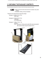
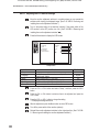
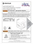
3. CHECKING THE PACKAGE CONTENTS
The product packages shipped from the factory contain the following components and parts.
z Make sure that all the items shown below are contained in the product
packages.
z If any item is missing, contact your distributor.
Dimensions and contained items for the product packages
Packaging 1: 60” (W) x 31” (D) x 75” (H)
・Monitor Assy
Packaging 2: 60” (W) x 39” (D) x 75” (H)
・Control Assy
・Box 1 (Marquee Assy)
Packaging 3: 74” (W) x 51” (D) x 77” (H)
・Seat Assy
・Box 2 ( Roof Assy(1), CS bottom joint bracket(2), MC bottom joint bracket(2),
MC side joint bracket(2), Top joint bracket(2), Screws )
Control Assy
Seat Assy
Box 1
Box 2
Roof Assy
9
To Purchase This Item, Visit BMI Gaming | www.bmigaming.com | (800) 746-2255 | +561.391.7200
3. CHECKING THE PACKAGE CONTENTS
Accessory list
10
No.
Name
Qty.
1
Operation Manual (this manual)
2
Maintenance key
4
3
Cash box key
2
4
Coin door key
2
6
Torx wrench
M5, T25
1
7
Torx wrench
M6, T27
1
8
Power Cord
Op
er
at
io
n
Ma
nu
al
1
1
To Purchase This Item, Visit BMI Gaming | www.bmigaming.com | (800) 746-2255 | +561.391.7200
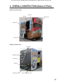
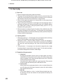
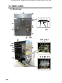
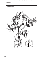
4. OVERALL CONSTRUCTION (Names of Parts)
General view (front side)
Seat Assy
Roof Assy
Marquee Assy
Monitor Assy
Control Assy
General view (rear side)
Air vent holes
Maintenace panel B
Monitor Assy
Rack Assy
Maintenace panel B
Cord box Assy(Power switch)
11
To Purchase This Item, Visit BMI Gaming | www.bmigaming.com | (800) 746-2255 | +561.391.7200
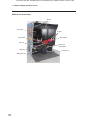
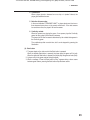
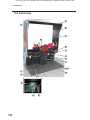
4. OVERALL CONSTRUCTION (Names of Parts)
Monitor and Control Assys
Speaker
LCD monitor
Triggers
1P Start button
2P Start button
Gun Assy
Service door
(service plate)
Wheel Assy
Coin box door
Maintenance door
12
To Purchase This Item, Visit BMI Gaming | www.bmigaming.com | (800) 746-2255 | +561.391.7200
5. INSTALLATION AND CARRY-IN PASSAGE CONDITIONS
,QVWDOOWKHPDFKLQHDFFRUGLQJWRWKHLQVWUXFWLRQVDQGSURFHGXUHVVSHFLÀHGLQWKLV
z
RSHUDWLRQPDQXDO)DLOXUHWRIROORZWKHVSHFLÀHGSURFHGXUHVPD\UHVXOWLQDÀUH
HOHFWULFVKRFNLQMXU\RUPDFKLQHPDOIXQFWLRQV
,QVHUWWKHSRZHUFRUGSOXJÀUPO\LQWRWKH$&RXWOHW3RRUFRQWDFWPD\FDXVHRYHUz
KHDWLQJWKDWFDQOHDGWRDÀUHRUEXUQV
%HVXUHWRFRQQHFWWKHJURXQGOHDG,IWKHJURXQGOHDGLVQRWFRQQHFWHGHOHFWULF
z
shock can result in case of electrical leakage. (See P. 56 “8A-1-7 Connecting the
power cord and ground lead.”)
,QVWDOOWKHPDFKLQHVHFXUHO\E\XVLQJWKHOHYHODGMXVWHUV8QVWDEOHPDFKLQHLQVWDOz
ODWLRQFDQUHVXOWLQDQDFFLGHQWRULQMXU\6HH3´$$GMXVWLQJOHYHODGMXVWers.”)
5-1 Installation conditions
'RQRWSODFHLWHPVQHDUWKHYHQWKROHVRQWKHUHDUSDQHORIWKH0RQLWRU$VV\RIWKH
z
JDPHPDFKLQHRUEORFNWKHPZLWKDZDOO,IWKRVHRSHQLQJVDUHEORFNHGWKHLQVLGH
RIWKHPDFKLQHEHFRPHVH[WUHPHO\KRWDQGÀUHRUPDOIXQFWLRQPD\UHVXOW
/RFDWLRQVWRDYRLG
7KHPDFKLQHLVGHVLJQHGIRULQGRRUXVH1HYHULQVWDOOWKHPDFKLQHRXWGRRUVRUDW
z
DQ\RIWKHIROORZLQJSODFHV
Place in direct sunlight
3ODFHH[SRVHGWRUDLQRUZDWHUOHDNDJH
Damp place
'XVW\SODFH
&ORVHWRKHDWLQJGHYLFHV
Hot place
([WUHPHO\FROGSODFH
3ODFHZKHUHGHZFRQGHQVDWLRQPD\RFFXUGXHWRWHPSHUDWXUHGLIIHUHQFHV
3ODFHZKHUHWKHPDFKLQHPD\EHFRPHDQREVWUXFWLRQLQHPHUJHQFLHVVXFK
DVQHDUHPHUJHQF\H[LWRUSODFHZKHUHÀUHH[WLQJXLVKHURUVLPLODUHTXLSPHQW
is installed
8QVWDEOHSODFHRUORFDWLRQZKHUHYLEUDWLRQVDUHSURGXFHG
13
To Purchase This Item, Visit BMI Gaming | www.bmigaming.com | (800) 746-2255 | +561.391.7200
5. INSTALLATION AND CARRY-IN PASSAGE CONDITIONS
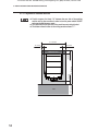
3OD\]RQHIRULQVWDOOHGPDFKLQH
z 3URYLGH D VSDFH RI DW OHDVW · µ EHWZHHQ WKH UHDU VLGH RI WKH PDFKLQH
and the wall or other machine in order to turn the power switch ON/OFF
DQGRSHQWKH0DLQWHQDQFHSDQHO
7KHYHQWKROHVRQWKHUHDUVLGHRIWKHPDFKLQHPXVWQRWEHEORFNHG
z
7KHGLVWDQFHIURPWKHÁRRUWRWKHFHLOLQJPXVWEHDWOHDVW·µ
z
9’ 2” or more
1’ 8” or more
1’ 8” or more
Aisle
14
11’ 6” or more
3’ 3” or more
1’ 8” or more
1’ 8” or more
Maintenance zone
To Purchase This Item, Visit BMI Gaming | www.bmigaming.com | (800) 746-2255 | +561.391.7200
5. INSTALLATION AND CARRY-IN PASSAGE CONDITIONS
5HTXLUHGGLPHQVLRQVRIFDUU\LQSDVVDJHVXFKDVGRRUV
and corridors)
The machine is divided into separate components at the factory before shipping. The dimensions of main components are as follows:
z Monitor Assy
56” (W) x 27” (D) x 72” (H)
Weight: 540 lbs.
z Control Assy
56” (W) x 32” (D) x 72”(H)
Weight: 485 lbs.
z Seat Assy
70” (W) x 40” (D) x 72”(H)
Weight: 232 lbs.
15
To Purchase This Item, Visit BMI Gaming | www.bmigaming.com | (800) 746-2255 | +561.391.7200
6. MOVING AND TRANSPORTING
Do not leave the machine on a slope. If the machine is left on a slope, it may tip
z
over and cause an unexpected accident.
0RYLQJRQWKHÁRRU
z Carefully transport the machine in order to prevent damage to the machine.
Do not apply excessive force to plastic parts since they can beak easily.
z
Even when moving the machine for a short distance, be sure to raise the
z
OHYHODGMXVWHUVDOOWKHZD\6HH3´$$GMXVWLQJOHYHODGMXVWHUVµ
Be sure to turn off the power switch before moving the machine.
z
Carefully handle power cord. (See P 56 “8A-1-7 Connecting the power
z
FRUGDQGJURXQGOHDGµ
16
To Purchase This Item, Visit BMI Gaming | www.bmigaming.com | (800) 746-2255 | +561.391.7200
6. MOVING AND TRANSPORTING
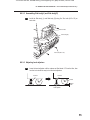
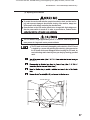
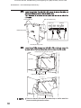
6-2 Transportation
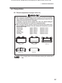
0DQXDOWUDQVSRUWDWLRQFDUU\LQJRQVWDLUVHWF
When carrying the machine manually, be sure to divide the machine into the Monitor
z
Assy, Control Assys, Seat Assy, Marquee Assy and Roof Assy and raise all the level
DGMXVWHUVDOOWKHZD\6HH3´$$VVHPEO\µ
$Q DWWHPSW WR FDUU\ WKH PDFKLQH PDQXDOO\ RYHU VWDLUV HWF ZLWKRXW GLYLGLQJ WKH
machine as described above can result in an unexpected accident.
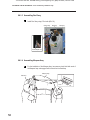
When carrying the machine manually, make sure that the following number of perz
sons are available. An attempt to carry the machine with fewer persons can result
in an accident or injury.
0RQLWRU$VV\
DSSUR[OEV
SHUVRQVRUPRUH
&RQWURO$VV\
DSSUR[OEV
SHUVRQVRUPRUH
6HDW$VV\
DSSUR[OEV
SHUVRQVRUPRUH
0DUTXHH$VV\
DSSUR[OEV SHUVRQVRUPRUH
5RRI$VV\
DSSUR[OEV SHUVRQVRUPRUH
Monitor Assy
Control Assy
Marquee Assy
Roof Assy
Seat Assy
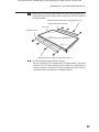
z Do not apply impact to the machine when lowering the machine from a
step.
17
To Purchase This Item, Visit BMI Gaming | www.bmigaming.com | (800) 746-2255 | +561.391.7200
7. OPERATION
z Some monitor sections remain hot or charged with high voltage even after the
power switch is turned off. Do not touch the monitor unnecessarily in order to
avoid electric shock and burns.
z 'XVWDFFXPXODWHGRQWKHSRZHUFRUGSOXJPD\FDXVHDÀUH&KHFNWKHSRZHUFRUG
plug regularly and remove dust.
z ,QVHUWWKHSRZHUFRUGSOXJÀUPO\LQWRWKH$&RXWOHW3RRUFRQWDFWPD\FDXVHRYHUKHDWLQJWKDWFDQOHDGWRDÀUHRUEXUQV
z Be sure to check that the machine has been installed according to the instructions
DQG SURFHGXUHV VSHFLÀHG LQ WKLV RSHUDWLRQ PDQXDO VHH 3 ´ ,167$//$7,21
$1'&$55<,13$66$*(&21',7,216µEHIRUHRSHUDWLQJWKHPDFKLQH,IWKHPDFKLQHLVQRWLQVWDOOHGSURSHUO\ÀUHHOHFWULFVKRFNLQMXU\RUHTXLSPHQWPDOIXQFWLRQ
can occur.
z The warning labels describe important safety precautions. Be sure to observe the
following:
To ensure that the warning labels attached to the machine are easily legible,
install the machine at an appropriate location with ample illumination and
keep the labels clean at all times. Also, make sure that the labels are not hidGHQEHKLQGDQRWKHUJDPHPDFKLQHRURWKHUREMHFWV
Do not remove or alter the warning labels.
If the warning labels become excessively dirty or damaged, replace them with
new labels. To order warning labels, contact your distributor.
z To ensure safe operation of the machine, be sure to conduct the pre-service check
VHH3´3UHVHUYLFHFKHFNµDQGPDLQWHQDQFHVHH3´%0DLQWHQDQFHµ
described in this manual. Failure to conduct the pre-service check or maintenance
can result in an unexpected accident.
7-1 People who shouldn’t play
To ensure safety of players and prevent accidents, do not allow the following peoz
ple to play the game machine.
18
3HRSOHZKRDUHVLFNRUUHFRYHULQJIURPLQMXU\
3HRSOHZLWKKHDUWFRQGLWLRQV
3HRSOHLQSRRUSK\VLFDOFRQGLWLRQ
3HRSOHXQGHUWKHLQÁXHQFHRIDOFRKRO
3UHJQDQWZRPHQ
3HRSOHZKRGRQRWREVHUYHWKHZDUQLQJVLQGLFDWHGRQWKHPDFKLQH
To Purchase This Item, Visit BMI Gaming | www.bmigaming.com | (800) 746-2255 | +561.391.7200
7. OPERATION
6DIHW\SUHFDXWLRQVWREHREVHUYHGE\SOD\HUV
If a player becomes sick due to light stimulation or game images, have the person
z
stop playing the game immediately and let him/her rest.
In rare cases, stimulation by lights or video images can cause convulsion or a loss
z
of consciousness. If this happens, advise the player to consult a doctor as soon
DVSRVVLEOH:KHQSUHVFKRROFKLOGUHQSOD\UHTXHVWWKHLUSDUHQWVRUJXDUGLDQVWR
keep an eye on the children.
19
To Purchase This Item, Visit BMI Gaming | www.bmigaming.com | (800) 746-2255 | +561.391.7200
7. OPERATION
3UHVHUYLFHFKHFN
Check the following items before commencing operation.
If any problem is found, take corrective measures by referring to “8B-2 Troubleshooting”
on page 58.
6DIHW\FKHFNEHIRUHSRZHU21
z 7R SUHYHQW DFFLGHQWV DQG LQMXU\ EH VXUH WR FRQGXFW WKH SUHVHUYLFH FKHFN
GHVFULEHG LQ ´ 6DIHW\ FKHFN EHIRUH SRZHU 21µ RQ SDJH EHIRUH
commencing operation.
z 7RSUHYHQWDFFLGHQWVDQGLQMXU\EHVXUHWRFKHFNWKDWWKHPDFKLQHLVQRWLQVWDOOHG
LQDSODFHGHVFULEHGLQ´/RFDWLRQVWRDYRLGµRQSDJHEHIRUHFRPPHQFLQJ
operation.
z Operating the machine with damaged, broken or deteriorated parts, or with
LQFRUUHFWO\LQVWDOOHGSDUWVFDQFDXVHLQMXU\WRSOD\HUVRUSHRSOHQHDUWKHPDFKLQH
If an abnormality is found, replace defective parts immediately. To order parts,
contact your distributor.
(1) Are all warning indications in place? (See P. 3 “1-4 Description of warning labels
attached to the machine.”)
(2) Are the warning indications legible? (See P. 3 “1-4 Description of warning labels
attached to the machine.”)
(3) Are all level adjusters adjusted properly? (See P. 55 “8A-1-6 Adjusting level
adjusters.”)
(4) Is the specified play zone provided? (See P. 14 “5-1-2 Play zone of installed
machine.”)
(5) Are the power cord and communication cable routed so that they will not cause
players or other customers to trip?
(6) Are the power cord securely connected to the AC outlet and the power input socket
on the machine? (See P. 56 “8A-1-7 Connecting the power cord and ground lead.”)
(7) Is the power cord plug free of dust? (See P. 56 “8A-1-7 Connecting the power cord
and ground lead.”)
Check the following items after turning on the power switch. If an abnormality is found,
turn off the power switch immediately to stop operating the machine. Then, unplug the
power cord from the AC outlet and contact your distributor.
(8) Is any part of the power cord or plug abnormally hot?
(9) Does touching the machine give an electric shock?
(10) Is there a burning smell, abnormal noise or vibration?
(11) Are there any other signs of abnormality or malfunction?
To Purchase This Item, Visit BMI Gaming | www.bmigaming.com | (800) 746-2255 | +561.391.7200
7. OPERATION
2SHUDWLRQFKHFNDIWHUSRZHU21
Check the following items in the Test mode. (See P. 25 “7-5-2 Adjustment switches.”)
&KHFNWKHODPSVIRUSURSHURSHUDWLRQ'RWKHÀXRUHVFHQWODPSVDQG6WDUWEXWWRQV
light?)
(See P. 29 “7-6-4 Switch/sensor test (I/O TEST).”)
(2) Check the Start buttons for proper operation.
(See P. 29 “7-6-4 Switch/sensor test (I/O TEST).”)
(3) Check the wheel for proper operation.
(See P. 29 “7-6-4 Switch/sensor test (I/O TEST).”)
(4) Check the guns for proper operation.
(See P. 29 “7-6-4 Switch/sensor test (I/O TEST).”)
(5) Check the displayed image. (Does the monitor show images properly?)
(See P. 36 “7-6-5 Monitor adjustment (MONITOR TEST).”)
(6) Check the sound. (Is sound produced by each speaker?)
(See P. 38 “7-6-6 Sound adjustment (SOUND TEST).”)
To Purchase This Item, Visit BMI Gaming | www.bmigaming.com | (800) 746-2255 | +561.391.7200
7. OPERATION
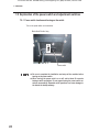
7-4 How to play
%DVLFUXOHV
1. Players shoot approaching enemy pirates and monsters.
2. The player’s life level decreases when the player is struck by a sword or bitten. If the
player fails to turn the wheel as instructed when it is necessary to do so, the life level
also decreases. When the life level decreases to 0, the game ends.
3. When a circular target mark appears on an enemy’s body or on the weapon thrown
by an enemy, shoot and destroy it.
4. There are two types of target marks: normal target marks and gold target marks. A
JROGWDUJHWPDUNDSSHDUVRQDVWURQJDQGSRZHUIXOHQHP\ZKRLVGLI¿FXOWWRGHVWUR\
Use “united shots” to destroy a strong and powerful enemy. (See P. 22 “7-4 (3)
Explanation of the game system.”)
5. When two persons are playing the game, the rating of the combination play of the
two players is displayed on the result screen. The combination play rating becomes
higher when the players use united shots effectively to destroy enemies and operate
the wheel skillfully to evade danger.
2SHUDWLQJPHWKRG
1. Shooting the golden gun — Pull the trigger on the gun-shaped controller (Gun Assy)
to shoot. When the trigger is held, the gun shoots consecutively.
2. Shooting the cannon — When the weapon changes to a cannon, pull the trigger to
shoot the cannon. To shoot the cannon continuously, it is necessary to pull the trigger
after each shot, unlike the golden gun. Also, there will be a time delay between
shots.
3. Turning the wheel — It is necessary to turn the wheel to navigate the ship or dodge
the enemy’s attack in some situations during the game. Turn the wheel according to
the instructions displayed on the screen to evade danger.
([SODQDWLRQRIWKHJDPHV\VWHP
1. United shot
By aligning the gunsights of the two guns on a target, players can launch a
united shot that is more powerful than an ordinary shot. When shooting united
shots, the gunsight on the screen becomes larger and the color of the shots
and the shooting sound also change.
Use united shots to destroy enemies with a gold target mark. Other enemies
can also be destroyed more easily when united shots are used.
3RZHUXSVKRW
When a player shoots a green gem placed on a ship or in pirates’ hide-out, the
gun of the player who shot the gem increases in power and is able to destroy
many enemies with each shot.
5HGFDVN
The red casks placed on a ship or in pirates’ hide-out explode when shot.
By shooting a red cask near enemies, the cask explodes and destroys the
enemies nearby.
To Purchase This Item, Visit BMI Gaming | www.bmigaming.com | (800) 746-2255 | +561.391.7200
7. OPERATION
4. Treasure box
When a player shoots a treasure box on a ship or in pirates’ hide-out, the
player gains additional scores.
6HOHFWLRQRIWUHDVXUHER[
In the event indicated ´TREASURE HUNT,µ a player selects one from two or
three treasure boxes shown on the screen and shoots it. If the shot treasure
box contains an item, the player’s life level increases.
&RQWLQXLW\URXOHWWH
When two persons are playing the game, if one person plays the Continuity
game, the other player’s life level also increases.
The amount of life level increase is determined by the roulette that appears in
the Continuity game.
The roulette stops after a certain time, but it can be stopped by pressing the
Start button.
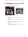
6WDUWEXWWRQ
1. The game starts on the side on which the Start button is pressed.
When the left-side Start button is pressed, the player plays the game as Eric (red).
When the right-side Start button is pressed, the player plays the game as Leah (blue).
2. A player can join the game anytime during the game.
3. When a message, ´Press the Start button to skip,µ appears during a demo scene
between game scenes, pressing the Start button skips the demo scene.
To Purchase This Item, Visit BMI Gaming | www.bmigaming.com | (800) 746-2255 | +561.391.7200
7. OPERATION
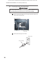
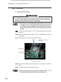
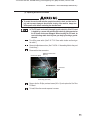
([SODQDWLRQRIWKHSRZHUVZLWFKDQGDGMXVWPHQWVZLWFKHV
3RZHUVZLWFKORFDWLRQDQGWXUQLQJRQWKHVZLWFK
Turn on the power switch on the machine.
Back side of Monitor Assy
ON
OFF
Power switch
z Be sure to complete the installation and setup of the machine before
turning on the power switch.
:KHQ WXUQLQJ WKH SRZHU VZLWFK RQ RU RII ZDLW DW OHDVW VHFRQGV
z
between switch operations. Do not repeat turning the power switch on
and off unnecessarily. Repeated on/off operations can cause damage to
the data in the backup memory.
To Purchase This Item, Visit BMI Gaming | www.bmigaming.com | (800) 746-2255 | +561.391.7200
7. OPERATION
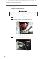
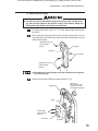
$GMXVWPHQWVZLWFKHV
Open the service door to gain access to the adjustment switches.
Service switch
Test switch
Enter switch
Select switch
Service door
D6HUYLFHVZLWFK
Press this switch to increase the credit count without activating the coin counter.
E6HOHFWVZLWFK
,QWKH7HVWPRGHÀLSWKLVVZLWFKXSRUGRZQWRVHOHFWDQLWHPRUVHWWLQJQXPHULFYDOXH
F7HVWVZLWFK
Set this switch to ON to activate the Test mode. The Test mode is used to test the
monitor and others. (See P. 26 “7-6 Test mode.”)
G(QWHUVZLWFK
After selecting an item or setting (numeric value) with the Select switch, press this
switch to enter or execute the selection.
To Purchase This Item, Visit BMI Gaming | www.bmigaming.com | (800) 746-2255 | +561.391.7200
7. OPERATION
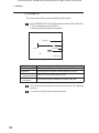
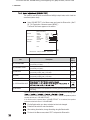
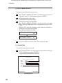
7-6 Test mode
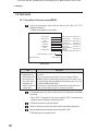
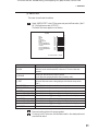
'HVFULSWLRQRIWKHPHQXVFUHHQ0(18
Unlock the service door and set the Test switch to ON. (See P. 25 ´7-5-2
Adjustment switches.µ)
The Menu screen appears on the monitor.
MENU
GAME OPTIONS
Setting of game fee and others Refer to Section 7-6-2.
Setting of game details
Refer to Section 7-6-3.
I/O TEST
Testing of switches, sensors, etc. Refer to Section 7-6-4.
COIN OPTIONS
MONITOR TEST
SOUND TEST
Adjustment of monitor
BOOKKEEPING
Bookkeeping data
Refer to Section 7-6-7.
Testing of PCB, initialization of Refer to Section 7-6-8.
memory, etc.
Software update
(Not used under normal conditions) Refer to Section 7-6-9.
OTHERS
SOFTWARE UPDATE
The internal battery01 is dead.
SELECT SW:CHOOSE
Refer to Section 7-6-5.
Adjustment of sound level, etc. Refer to Section 7-6-6.
(a)
ENTER SW:ENTER
0HQXVFUHHQ
Item
Description
(a) This error message
appears when the
internal battery of the
Rack Assy runs out.
(The number shown
immediately after
´batteryµ may be ´02µ
in some cases.)
When this message appears, turn off the power switch and wait for about
10 minutes.
Then, turn on the power switch again. If an error message, ´BACKUP
MEMORY ERROR,µ appears during the startup, set the Test switch to ON
to activate the Test mode and initialize the backup memory (see P 40 ´7-6-8
(4) BACKUP MEMORY INITIALIZE.µ).
If the same error is generated after the power switch is turned off and on
again, the internal battery may be low in capacity or defective.
Flip the Select switch up or down to select an item. The selected item is indicated
by blinking.
* When ´EXIT” is displayed on the screen, selecting ´EXITµ and entering the
selection returns the display to the previous screen.
Press the Enter switch to enter the selection.
When the selection is entered, the screen shows the applicable setting items.
After all adjustments are completed, set the Test switch to OFF.
The display returns to the game screen.
To Purchase This Item, Visit BMI Gaming | www.bmigaming.com | (800) 746-2255 | +561.391.7200
7. OPERATION
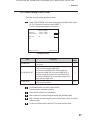
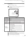
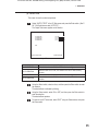
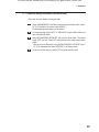
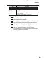
*DPHIHHVHWWLQJ&2,1237,216
This screen is used to set the game fee and others.
Select ´COIN OPTIONSµ in the Menu screen and press the Enter switch. (See P.
26 ´7-6-1 Description of the menu screen (MENU).µ)
The Coin Options screen appears on the monitor.
COIN OPTIONS
[DEFAULT IN GREEN]
GAME COST
CONTINUE COST
2 COIN(S) 1 CREDIT
1 COIN(S) 1 CREDIT
(a)
(b)
FREE PLAY
OFF
(c)
EXIT
SELECT SW:CHOOSE
ENTER SW:ENTER
&RLQ2SWLRQVVFUHHQ
Item
Description
Default
setting
(a) GAME COST
Set the number of coins required to play the game.
1 to 19 coins
2
(b) CONTINUE COST
Set the number of coins required to play Continuity game.
1 coin to the value entered in GAME COST
The value set in CONTINUE COST cannot be larger than
the value set in GAME COST. If the value in GAME COST is
reduced to a value lower than the value in CONTINUE COST,
the value in CONTINUE COST is automatically changed to the
same value set in GAME COST.
1
(c) FREE PLAY
ON (Free play available)
OFF(Free play unavailable)
OFF
Flip the Select switch up or down to select an item.
The selected item is indicated by blinking.
Press the Enter switch to enter the selection.
After the selection is entered, change the setting using the Select switch.
After the setting has been changed, press the Enter switch to return to the item
selection screen.
To return to the Menu screen, select “EXIT” and press the Enter switch.
To Purchase This Item, Visit BMI Gaming | www.bmigaming.com | (800) 746-2255 | +561.391.7200
7. OPERATION
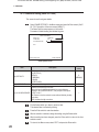
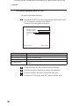
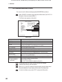
*DPHGHWDLOVHWWLQJ*$0(237,216
This screen is used to set game details.
Select ´GAME OPTIONSµ in the Menu screen and press the Enter switch. (See P.
26 ´7-6-1 Description of the menu screen (MENU).µ)
The Game Options screen appears on the monitor.
Parameters in default setting are indicated in green.
GAME OPTIONS
[DEFAULT IN GREEN]
DIFFICULTY
LASER SIGHT
HI-SCORE INITIALIZE
C(MEDIUM)
ON
(a)
(b)
(c)
EXIT
SELECT SW:CHOOSE
ENTER SW:ENTER
*DPH2SWLRQVVFUHHQ
Item
Default
setting
Description
(a) DIFFICULTY
6HWWKHJDPHGLI¿FXOW\OHYHO
A (VERY EASY)
B (EASY)
C (MEDIUM)
D (HARD)
E (VERY HARD)
(b) LASER SIGHT
Shows a line from the gun to the crosshair aim to assist player.
ON
(c) HI-SCORE INITIALIZE
Initializes the stored high score data.
When this item is selected and entered, the screen displays a
message, ´HI-SCORE INITIALIZE?,µ and prompts for the input of
´YESµ or ´NO.µ
NO: Returns to the item selection screen without initializing the high
score data.
YES: Initializes the high score data.
—
C
(MEDIUM)
Flip the Select switch up or down to select an item.
The selected item is indicated by blinking.
Press the Enter switch to enter the selection.
After the selection is entered, change the setting using the Select switch.
After the setting has been changed, press the Enter switch to return to the item
selection screen.
To return to the Menu screen, select “EXIT” and press the Enter switch.
To Purchase This Item, Visit BMI Gaming | www.bmigaming.com | (800) 746-2255 | +561.391.7200
7. OPERATION
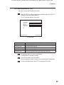
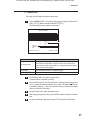
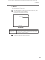
6ZLWFKVHQVRUWHVW,27(67
This screen is used to test the switches and others.
Select ´I/O TESTµ in the Menu screen and press the Enter switch. (See P. 26 “7-6-1
Description of the menu screen (MENU).”)
The I/O Test screen appears on the monitor.
I/O TEST
(a)
(b)
(c)
(d)
(e)
I/O PCB CHECK
SWITCH TEST
GUN TEST
STEERING TEST
OUTPUT TEST
EXIT
SELECT SW:CHOOSE
ENTER SW:ENTER
I/O Test screen
Item
Description
(a) I/O PCB CHECK
Checks the I/O PC Board.
(b) SWITCH TEST
Executes the switch input test.
(c) GUN TEST
Executes the Gun Assy test, initializes the Gun Assys.
(d) STEERING TEST
Executes the wheel test.
(e) OUTPUT TEST
Executes the illuminated button test and Gun Assy vibration test.
Flip the Select switch up or down to select an item.
The selected item is indicated by blinking.
Press the Enter switch to enter the selection.
When the selection is entered, the screen shows the details of the selected item.
To return to the Menu screen, select “EXIT” and press the Enter switch.
To Purchase This Item, Visit BMI Gaming | www.bmigaming.com | (800) 746-2255 | +561.391.7200
7. OPERATION
,23&%&+(&.
7KLVVFUHHQLVXVHGWRFRQ¿UPWKHFRQGLWLRQRIWKH86,23&%RDUG
I/O PCB CHECK
I/O PCB : Connect OK
(a)
NBGI.;USIO01;VerX.XX;JPN,Mulitipurpose with PPG
EXIT
SELECT SW : CHOOSE
ENTER SW : ENTER
,23&%&KHFNVFUHHQ
Item
(a) I/P PCB
Description
Displays “CONNECT OK” when the PC Board is normal.
To return to the I/O Test screen, select “EXIT” and press the Enter button.
To Purchase This Item, Visit BMI Gaming | www.bmigaming.com | (800) 746-2255 | +561.391.7200
7. OPERATION
6:,7&+7(67
This screen is used to test the switches.
Select “SWITCH TEST” in the I/O Test screen and press the Enter switch. (See P.
29 “7-6-4 Switch/sensor test (I/O TEST).”)
The Switch Test screen appears on the monitor.
SWITCH TEST
[ON:RED]
COIN
SERVICE
TEST
UP SELECT
DOWN SELECT
ENTER
1P GUN TRIGGER LEFT
1P GUN TRIGGER RIGHT
1P START
2P GUN TRIGGER LEFT
2P GUN TRIGGER RIGHT
2P START
0
OFF
ON
OFF
OFF
OFF
OFF
OFF
OFF
OFF
OFF
OFF
(a)
(b)
(c)
(d)
(e)
(f )
(g)
(h)
(i)
(j)
(k)
(l)
UP SELECT+ENTER
SW:EXIT
Switch Test screen
Item
Description
(a) COIN
The counter increments by 1 each time the coin switch receives input.
When the counter value exceeds 255, it returns to 0. The coin counter also
operates.
(b) SERVICE
Shows “ON” while the Service switch is pressed.
(In the Test mode, pressing the switch does not add any credit.)
(c) TEST
Shows “ON” when the Test switch is set to ON.
(Since the Test mode screen is being displayed, this indication always shows
“ON.”)
(d) UP SELECT
Shows “ON” while the Select switch is in the raised position
(e) DOWN SELECT
Shows “ON” when the Select switch is the lowered position.
(f) ENTER
Shows “ON” while the Enter switch is pressed.
(g) 1P GUN TRIGGER LEFT
Shows “ON” while the Trigger button (left) on the 1P-side Gun Assy is pressed.
(h) 1P GUN TRIGGER RIGHT
Shows “ON” while the Trigger button (right) on the 1P-side Gun Assy is pressed.
(i) 1P START
Shows “ON” while the 1P-side Start button is pressed.
(j) 2P GUN TRIGGER LEFT
Shows “ON” while the Trigger button (left) on the 2P-side Gun Assy is pressed.
(k) 2P GUN TRIGGER RIGHT
Shows “ON” while the Trigger button (right) on the 2P-side Gun Assy is pressed.
(l) 2P START
Shows “ON” while the 2P-side Start button is pressed.
Press each switch and check for proper operation.
To return to the I/O Test screen, hold the Select switch in the raised position and
press the Enter switch.
To Purchase This Item, Visit BMI Gaming | www.bmigaming.com | (800) 746-2255 | +561.391.7200
7. OPERATION
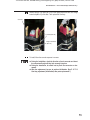
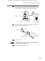
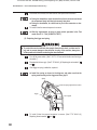
*817(67
This screen is used to test and initialize the gunsights of the Gun Assys and test the
operation of the gun vibration units.
z $IWHUPDLQWDLQLQJRUUHSODFLQJD*XQ$VV\RU86,23&%RDUGEHVXUHWR
FRQGXFWWKHFDOLEUDWLRQGHVFULEHGLQ´*81&$/,%5$7,21µRQSDJH
Select “GUN TEST” in the I/O Test screen and press the Enter switch. (See P. 29
“7-6-4 Switch/sensor test (I/O TEST).”)
The Gun Test screen appears on the monitor.
GUN TEST
1P START
2P START
(a)
(b)
OFF
OFF
(1)
(2)
1P X: FFFF Y: 0000
2P X: 0000 Y: FFFF
(3)
(4)
1
PULL GUN TRIGGER TO ACTION
SERVICE SW:CALIBRATION
ENTER SW:ENTER
*XQ7HVWVFUHHQ
Item
Description
(a) 1P START
Shows the status of the Start button on the 1P-side Gun Assy. *2
(b) 2P START
Shows the status of the Start button on the 2P-side Gun Assy. *2
(1) 1P X-coordinate,
Y-coordinate
Shows the X and Y coordinates of the crosshair aim of the 1P-side gun.
(2) 2P X-coordinate,
Y-coordinate
Shows the X and Y coordinates of the crosshair aim of the 2P-side gun.
(3) Gun crosshairs (red)
Shows the crosshair aim of the 1P-side Gun Assy on the screen.
(4) Gun crosshairs (blue)
Shows the crosshair aim of the 2P-side Gun Assy on the screen.
*1 The vibration unit operates when the trigger on a Gun Assy is pulled.
*2 The Start button lights when it is pressed.
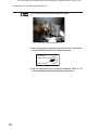
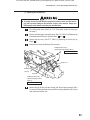
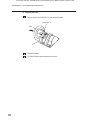
Loosen the wing bolt, move the service switch cover to a side, and press the
Service switch to display the calibration setting screen.
(See P. 33 “7-6-4 (4) GUN CALIBRATION.”)
To return to the I/O Test screen, press the Enter switch.
To Purchase This Item, Visit BMI Gaming | www.bmigaming.com | (800) 746-2255 | +561.391.7200
7. OPERATION
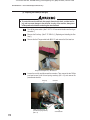
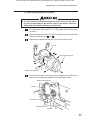
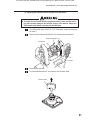
*81&$/,%5$7,21
This screen is used to calibrate the Gun Assys.
Press the Service switch while the Gun Test screen is displayed. (See P. 32 “7-6-4
(3) GUN TEST.”)
The Gun Calibration screen appears on the monitor.
GUN CALIBRATION
(1)
(2)
1P X: AAAA Y: 6666
2P X: 6666 Y: AAAA
(3)
(4)
1P: SHOOT THE LEFT END
2P: SHOOT THE LEFT END
(a)
ENTER SW:EXIT
*XQ&DOLEUDWLRQVFUHHQ
Item
Description
(1) Gun crosshairs (red)
Shows the location of the crosshairs of the 1P-side Gun Assy (after completion of
adjustment).
(2) Gun crosshairs (blue)
Shows the location of the crosshairs of the 2P-side Gun Assy (after completion of
adjustment).
(3) 1P X-coordinate,
Y-coordinate
Shows the X and Y coordinates of the crosshairs of the 1P-side gun.
(4) 2P X-coordinate,
Y-coordinate
Shows the X and Y coordinates of the crosshairs of the 2P-side gun.
(a) Displays the
procedure for
calibrating the gun
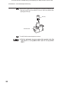
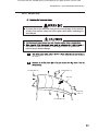
Gun calibration can be performed by moving and operating each Gun Assy on the 1P
and 2P sides as shown below.
(1) [SHOOT THE LEFT END]
Move the gun all the way to the left and press the Trigger button once.
(2) [SHOOT THE RIGHT EDGE]
Move the gun all the way to the right and press the Trigger button once.
(3) [SHOOT THE TOP]
Move the gun all the way to the top and press the Trigger button once.
(4) [SHOOT THE BOTTOM]
Move the gun all the way to the bottom and press the Trigger button once.
(5) [FINISHED]
The calibration has been completed. The adjustment data is saved and the
crosshairs appear on the screen.
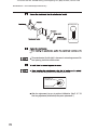
Move the gun being calibrated all the way to the left and press the Trigger button once.
The left limit position of the crosshairs is set.
In the same manner, press the Trigger button each time after moving the gun all
the way to the right, to the top and then to the bottom.
To return to the Gun Test screen, press the Enter switch.
To Purchase This Item, Visit BMI Gaming | www.bmigaming.com | (800) 746-2255 | +561.391.7200
7. OPERATION
67((5,1*7(67
This screen is used to test the sensor for detecting the wheel rotation.
Select “STEERING TEST” in the I/O Test screen and press the Enter switch. (See
P. 29 “7-6-4 Switch/sensor test (I/O TEST).”)
The Steering Test screen appears on the monitor.
STEERING TEST
(2)
STEERING 01
(2)
LEFT OK
RIGHT OK
(3)
(4)
EXIT
ENTER SW:EXIT
Steering Test screen
Item
Description
(1) Wheel counter
Displays the wheel count.
(2) Wheel bar
The bar graph shows the wheel movement detected by the sensor.
(3) Wheel sensitivity
stability measurement
Displays “OK” when the wheel sensor is normal.
(4) Wheel rotation speed
measurement
7KHZKHHOWXUQLQJVSHHGLVLQGLFDWHGE\WKHQXPEHURI³Ŷ´PDUNV
Turn the wheel to the left and then to the right to make sure that “OK” is displayed
each time.
To return to the I/O Test screen, press the Enter switch.
To Purchase This Item, Visit BMI Gaming | www.bmigaming.com | (800) 746-2255 | +561.391.7200
7. OPERATION
2873877(67
This screen is used to conduct output tests.
Select “OUTPUT TEST” in the I/O Test screen and press the Enter switch. (See P.
29 “7-6-4 Switch/sensor test (I/O TEST).”)
The Output Test screen appears on the monitor.
OUTPUT TEST
1P START LED
1P VIBRATION
2P START LED
2P VIBRATION
(a)
(b)
(c)
(d)
OFF
OFF
OFF
OFF
EXIT
SELECT SW:CHOOSE
ENTER SW:ENTER
Output Test screen
Item
Description
(a) 1P START LED
When this item is set to “ON,” the 1P-side Start button lights.
(b) 1P VIBRATION
When this item is set to “ON,” the vibration unit of the 1P-side Gun Assy
vibrates.
(c) 2P START LED
When this item is set to “ON,” the 2P-side Start button lights.
(d) 2P VIBRATION
When this item is set to “ON,” the vibration unit of the 2P-side Gun Assy
vibrates.
Using the Select switch, select an item, and then press the Enter switch to enter
the selection.
The selected item is indicated by blinking.
Using the Select switch, select ON or OFF, and then press the Enter switch to
enter the selection.
The selected item operates.
To return to the I/O Test screen, select “EXIT” using the Select switch, and press
the Enter switch.
To Purchase This Item, Visit BMI Gaming | www.bmigaming.com | (800) 746-2255 | +561.391.7200
7. OPERATION
0RQLWRUDGMXVWPHQW021,7257(67
This screen is used to adjust the monitor.
Select “MONITOR TEST” in the Menu screen and press the Enter switch. (See P.
26 “7-6-1 Description of the menu screen (MENU).”)
The Monitor Test screen appears on the monitor.
MONITOR TEST
(a)
(b)
(c)
(d)
GRADATION PATTERN
CROSSHATCH PATTERN
FULL WHITE
GAMMA ADJUST
EXIT
SELECT SW : CHOOSE
ENTER SW : ENTER
0RQLWRU7HVWVFUHHQ
Item
Description
(a) GRADATION PATTERN
Displays a 16-step gradation pattern.
(b) CROSSHATCH PATTERN
Displays a crosshatch pattern.
(c) FULL WHITE
Displays all-white screen.
(d) GAMMA ADJUST
Displays the gamma adjustment screen. (See P. 37 “7-6-5 (1) GAMMA
ADJUST.”)
Flip the Select switch up or down and select an item to be changed.
Press the Enter switch to display the test screen for the selected item.
To return to the Monitor Test screen, press the Enter switch again.
To return to the I/O Test screen, select “EXIT” and press the Enter switch.
To Purchase This Item, Visit BMI Gaming | www.bmigaming.com | (800) 746-2255 | +561.391.7200
7. OPERATION
*$00$$'-867
This screen is used to adjust the gamma values (color).
Select “GAMMA ADJUST” in the Monitor Test screen and press the Enter switch.
(See P. 35 “7-6-5 Monitor adjustment (MONITOR TEST).”)
The Gamma Adjust screen appears on the monitor.
GAMMA ADUST
[DEFAULT IN GREEN]
R
G
B
1.00
0.93
9.99
(a)
(b)
(c)
DEFAULT
SAVE & EXIT
EXIT
SELECT SW : CHOOSE
ENTER SW : ENTER
*DPPD$GMXVWVFUHHQ
Item
Description
(a) Gamma values
Change the gamma value for each of R, G and B.
Each value can be adjusted in a range of 0.00 to 1.00 in intervals of 0.01.
(The value increments or decrements by 0.1 when the Select switch is kept
in the raised or lowered position.)
(b) DEFAULT
Returns all gamma values to 1.00 (default setting).
(c) SAVE & EXIT
Saves the settings and returns to the Monitor Test screen.
Flip the Select switch up or down to select an item.
The selected item is indicated by blinking.
Press the Enter switch to enter the selected item. Selecting and entering the item
ERUFUHÀHFWVWKHVHWWLQJVGLVSOD\HGRQWKHVFUHHQ3URFHHGWR when (a)
is selected. Proceed to
when (b) is selected. When (c) is selected, the display
returns to the Monitor Test screen.)
Using the Select switch, adjust the gamma value.
After changing the gamma values, press the Enter switch for selection of another
item.
To return to the Monitor Test screen, select “EXIT” and press the Enter switch.
To Purchase This Item, Visit BMI Gaming | www.bmigaming.com | (800) 746-2255 | +561.391.7200
7. OPERATION
This screen is used to set the sound level and left/right output levels, and to check the
sound level (stereo check).
Select “SOUND TEST” in the Menu screen and press the Enter switch. (See P.
26 “7-6-1 Description of the menu screen (MENU).”)
The Sound Test screen appears on the monitor.
SOUND TEST
[DEFAULT IN GREEN]
VOLUME
SURROUND
GAME
ATTRACT
BGM & SE
VOICE
SOUND MODE
BALANCE
(0 15)
(0 15)
100%
100%
2.1 CH
-3dB
MESSAGE
GAME
LEFT
OUTPUT LEVEL
11
11
(a)
(b)
(c)
(d)
(e)
(f )
(g)
EXIT
SELECT SW:CHOOSE SERVICE SW: SPEAKER TEST ENTER SW:ENTER
Sound Test screen
Item
Description
Default
setting
(a) VOLUME GAME
Set the general sound level in the game mode.
0 (no sound) to 15 (max.)
11
(b) VOLUME ATTRACT
Set the general sound level in the Attract mode.
0 (no sound) to 15 (max.)
11
(c) BGM & SE
Set the sound output level of the background music and sound effects.
0 (no sound) to 100% (max.), 10% steps
100%
(d) VOICE
Set the sound output level of the characters’ voices.
0 (no sound) to 100% (max.), 10% steps
100%
(e) SOUND MODE
5.1 CH/2.1 CH/2 CH (This setting is not changed under normal conditions
2.1 CH
FIX
(5.1 ch)
(f) SURROUND BALANCE
(2.1 ch)
(g) MESSAGE
Indicates the location of the speaker that is currently producing sound and its sound
level setting.
* When the Service switch is pressed, the speakers start producing sound in the following order.
When the Service switch is pressed with “VOLUME ATTRACT” selected, the speakers produce
sound at the level set in “VOLUME ATTRACT.”
If the Service switch is pressed when “VOLUME ATTRACT” is not selected, the speakers
produce sound at the level set in “VOLUME GAME.”
Flip the Select switch up or down and select an item to be changed.
Press the Enter switch to enter the selection.
After entering the selection, change the setting using the Select switch.
To return to the Menu screen, select “EXIT” and press the Enter switch.
To Purchase This Item, Visit BMI Gaming | www.bmigaming.com | (800) 746-2255 | +561.391.7200
7. OPERATION
*DPHGDWDGLVSOD\LQLWLDOL]DWLRQ%22..((3,1*
This screen is used to display various game data.
Select “BOOKKEEPING” in the Menu screen and press the Enter switch. (See P.
26 “7-6-1 Description of the menu screen (MENU).”)
The Bookkeeping screen appears on the monitor.
To change the page, select “NEXT” or “PREVIOUS” using the Select switch, and
then press the Enter switch.
Select “BOOKKEEPING INITIALIZE” and press the Enter switch. The screen
shows “YES” and “NO.” Select “YES” and press the Enter switch to clear data to
default.
* Data can also be initialized by using “BACKUP MEMORY INITIALIZE” (see P.
40 “7-6-8. Initialization and others (OTHERS)”) in the Others screen.
To return to the Menu screen, select “EXIT” and press the Enter switch.
To Purchase This Item, Visit BMI Gaming | www.bmigaming.com | (800) 746-2255 | +561.391.7200
7. OPERATION
,QLWLDOL]DWLRQDQGRWKHUV27+(56
This screen is used to initialize bookkeeping data (BOOKKEEPING) and others.
Select “OTHERS” in the Menu screen and press the Enter switch. (See P. 26 “7-6-1
Description of the menu screen (MENU).”)
The Others screen appears on the monitor.
OTHERS
[DEFAULT IN GREEN]
ROM
DSP100-2-NA-MPR0-BXX
CLOCK
01/01/2010 FRI 08:11:24
S/N
76C0D0-9XXXXX
SYSTEM SW
Ver. 250.XXX
CABINET TYPE
SD
LANGUAGE
ENG
ATTRACT CUT
OFF
RATING
OFF
HDD CHECK
CLOCK SETTING
BACKUP MEMORY INITIALIZE
EXIT
SELECT SW:CHOOSE
(1)
(2)
(3)
(4)
(a)
(b)
(c)
(d)
(e)
(f )
ENTER SW:ENTER
Others screen
Item
Description
(1) ROM
Shows the version of the program on the hard disk.
(2) CLOCK
Shows the internal clock time.
(3) S/N
Shows the software serial No.
(Indicates “NO USB KEY” if the USB dongle is not installed.)
(4) SYSTEM SW
Shows the system software version.
(a) LANGUAGE
Shows the language setting. (“JPN” (Japanese))
(b) ATTRACT CUT
This is used to set whether to display the Attract demo scenes.
(c) RATING
This is used to set the color of damage display (OFF: Red, ON: Green).
(d) HDD CHECK
This is used for checking the hard disk.
(See P. 41 “7-6-8 (3) HDD CHECK.”)
(e) CLOCK SETTING
This is used to set the internal clock. (See. P. 42 “7-6-8 (3) CLOCK SETTING.”)
(f) BACKUP MEMORY
INITIALIZE
This is used to initialize the backup memory.
(YES: Initialize, NO: Abort)
(See P. 42 “ 7-6-8 (2) BACK UP MEMORY INITIALIZE.”)
Flip the Select switch up or down and select an item to be changed.
Press the Enter switch to enter the selection.
When (a), (b), (c) and (f) is selected, change the setting using the Select switch.
When (d) is selected, the screen displays the information of the selected item.
To return to the Menu screen, select “EXIT” and press the Enter switch.
To Purchase This Item, Visit BMI Gaming | www.bmigaming.com | (800) 746-2255 | +561.391.7200
7. OPERATION
This screen displays the HDD check result.
Select HDD CHECK in the Others screen and press the Enter switch. (See P.
40 7-6-8 Initialization and others (OTHERS). )
The HDD Check screen appears on the monitor.
HDD CHECK
MEDIA OK!
(a)
ENTER SW:EXIT
Item
(a) MEDIA OK!
Description
The installed hard disk is normal.
If the above screen is not displayed, the hard disk or Rack Assy (SYS369)
may be defective. Contact your distributor.
To return to the Others screen, press the Enter switch.
41
To Purchase This Item, Visit BMI Gaming | www.bmigaming.com | (800) 746-2255 | +561.391.7200
7. OPERATION
%$&.830(025<,1,7,$/,=(
This screen is used to initialize the backup memory.
Select ´BACK UP MEMORY INITIALIZEµ in the Others screen and press the
Enter switch. (See P. 40 ´7-6-8 Initialization and others (OTHERS).µ)
Using the Select switch, select an item.
The selected item is indicated by blinking.
Press the Enter switch to enter the selection.
When ´BACK UP MEMORY INITIALIZEµ is selected and entered, the screen
displays ´BACK UP MEMORY INITIALIZEµ and prompts for the input of ´YESµ
or ´NO.µ
Selecting ´YESµ starts the initialization process. When the initialization is
¿QLVKHGGDWDLQWKHPHPRU\UHWXUQWRGHIDXOW
Select ´BACK UP MEMORY INITIALIZE.µ
BACK UP MEMORY INITIALIZE?
NO
YES
Select ´YES.µ
BACK UP MEMORY INITIALIZE
OK
To return to the Menu screen, select ´EXITµ and press the Enter switch.
&/2&.6(77,1*
This screen is used to set the internal clock.
Select ´CLOCK SETTINGµ in the Others screen and press the Enter switch. (See
P. 40 ´7-6-8 Initialization and others (OTHERS).µ)
The Clock Setting screen appears on the monitor.
CLOCK SETTING
CLOCK
YEAR
MONTH
DAY
HOUR
MINUTE
'04/01/2010 THU 19:28:56
(a)
(b)
(c)
(d)
(e)
10 +2000
04
01
19
03
(f )
SET
EXIT
SELECT SW:CHOOSE
&ORFN6HWWLQJVFUHHQ
ENTER SW:ENTER
To Purchase This Item, Visit BMI Gaming | www.bmigaming.com | (800) 746-2255 | +561.391.7200
7. OPERATION
Item
Description
(a) YEAR
Setting of the year (00 to 99)
(b) MONTH
Setting of the month (01 to 12)
(c) DAY
Setting of the day (01 to 31)
(d) HOUR
Setting of the hour (00 to 23)
(e) MINUTE
Setting of the minute (00 to 59)
(f) SET
Enter the clock settings.
The values (1) through (e) are set in the internal clock.
Using the Select switch, select an item.
The selected item is indicated by blinking.
Press the Enter switch to enter the selection.
After selecting an item, change the setting using the Select switch.
After changing the setting, press the Enter switch for selection of another item.
After changing the items (a) through (e), select ´SETµ and press the Enter switch
to enter the settings in the internal clock. The clock starts from the set date/time
at 00 second.
Select ´EXITµ and press the Enter switch to return to the Menu screen.
Set the Test switch to OFF to return to the game screen, and then check to make
sure that the clock displays the correct date/time.
To Purchase This Item, Visit BMI Gaming | www.bmigaming.com | (800) 746-2255 | +561.391.7200
7. OPERATION
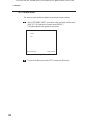
7-6-9 Software update
This screen is used to update the software (not used under normal conditions).
Select ´SOFTWARE UPDATEµ in the Menu screen and press the Enter switch.
(See P. 26 ´7-6-1 Description of the menu screen (MENU).µ)
The Software Update screen appears on the monitor
SOFTWARE UPDATE
UPDATE
EXIT
SELECT SW:CHOOSE
ENTER SW:ENTER
Software Update screen
To return to the Menu screen, select “EXIT” and press the Enter switch.
44
To Purchase This Item, Visit BMI Gaming | www.bmigaming.com | (800) 746-2255 | +561.391.7200
7. OPERATION
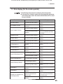
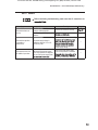
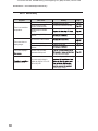
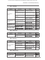
(UURUGLVSOD\IRUWKHDUFDGHRSHUDWRU
z The following shows items to be checked by the arcade operator.
z If the same error indication remains after the appropriate countermeasure has been taken, set the Test switch to ON and then to OFF to cancel
the error indication.
Error indication
&DXVH
Remedy
BATTERY02 ERROR
The Rack Assy PCB is defective.
Request a technician to correct the
problem.
NOT CONNECT I/O-PCB
The USIO PC Board or its harness
is defective.
Request a technician to correct the
problem.
The USIO PC Board is defective.
Request a technician to correct the
problem.
The data in the backup memory is
damaged.
Initialize the backup memory. (See P.
64 ´7-7-10 Initialization and others
(OTHERS).µ
FIRMWARE ERROR
The USIO PC Board is defective.
Request a technician to correct the
problem.
MEMORY ERROR
The USIO PC Board is defective.
Request a technician to correct the
problem.
SYSTEM ERROR 01
The Rack Assy PCB is defective.
Request a technician to correct the
problem.
SYSTEM ERROR 02
The Rack Assy PCB or hard disk is
defective.
Request a technician to correct the
problem.
SYSTEM ERROR 03
The Rack Assy PCB or hard disk is
defective.
Request a technician to correct the
problem.
SYSTEM ERROR 04
The Rack Assy PCB or hard disk is
defective.
Request a technician to correct the
problem.
The USB dongle is defective.
Request a technician to correct the
problem.
A wrong USB dongle is installed.
Request a technician to correct the
problem.
The USB dongle is not installed.
Request a technician to correct the
problem.
The USB dongle is defective.
Request a technician to correct the
problem.
The Rack Assy PCB is defective.
Request a technician to correct the
problem.
COIN ERROR1
The coin selector or its harness is
defective.
Request a technician to correct the
problem.
COIN ERROR2
The Service switch or its harness is
defective.
Request a technician to correct the
problem.
This error is indicated during a
game play activated with the
Service switch.
It is normal if the error is displayed
during a game play activated with
the Service switch.
The Service switch or its harness is
defective.
Request a technician to correct the
problem.
BACKUP MEMORY ERROR
USB-KEY ERROR(INVALID KEY)
USB-KEY ERROR(NO KEY)
USB-KEY ERROR(IO ERROR)
SERVICE PLAY (indicated at the
Credit display location)
To Purchase This Item, Visit BMI Gaming | www.bmigaming.com | (800) 746-2255 | +561.391.7200
7. OPERATION
Error indication
ERROR 55
46
&DXVH
Remedy
The data in the machine is
damaged.
Contact your distributor.
USB dongle of a different machine
unit is installed.
Request a technician to correct the
problem.
To Purchase This Item, Visit BMI Gaming | www.bmigaming.com | (800) 746-2255 | +561.391.7200
7. OPERATION
*XQ$VV\DGMXVWPHQWLQLWLDOL]DWLRQDIWHUSDUWVUHSODFHPHQW
z %H VXUH WR LQLWLDOL]H WKH *XQ$VV\V DIWHU UHSODFLQJ WKH 5DFN$VV\
6<6 86,2 3& %RDUG RU *XQ$VV\ RU DIWHU LQLWLDOL]LQJ WKH EDFNXS
GDWD,IWKH*XQ$VV\VDUHQRWLQLWLDOL]HGWKHJDPHPDFKLQHZLOOQRWRSerate properly.
z $IWHULQLWLDOL]LQJWKH*XQ$VV\VPDNHVXUHWKDWWKHJXQVRSHUDWHSURSHUO\E\FRQGXFWLQJWKHVZLWFKWHVWVHH3´*817(67µ
,QLWLDOL]LQJWKHYROXPHVLQWKH*XQ$VV\V
Initialize (calibration) the Gun Assys by referring to “7-6-4 (4) GUN CALIBRATION” on
page 33.
47
To Purchase This Item, Visit BMI Gaming | www.bmigaming.com | (800) 746-2255 | +561.391.7200
8. MANUAL FOR THE TECHNICIAN – To be conducted by a technician only –
NOTE!: GAME MUST BE ASSEMBLED IN IT'S FINAL PLAYZONE.
8A. Assembly and Setup – To be conducted by a technician only –
8A-1 Assembly – To be conducted by a technician only –
8A-1-1 Assembling Monitor Assy and Control Assy
Remove the four Torx bolts (M5 x 30) and remove a wood panel from Control
Assy. This panel is used for shipping only.
A wood panel for shipping
Torx bolts (M5 x 30)
Control Assy
Connect Monitor Assy with Control Assy. Install MC Bottom Joint Brackets using
two Torx bolts (M6 x 30) into the Monitor Assy bottom on the left and right sides.
Monitor Assy
Torx bolts (M6 x 30)
48
MC Bottom Joint Bracket
To Purchase This Item, Visit BMI Gaming | www.bmigaming.com | (800) 746-2255 | +561.391.7200
8A. MANUAL FOR THE TECHNICIAN – To be conducted by a technician only –
Connect each of the 3 connectors and install USB cable into USIO PC Board.
Then install MC Bottom Joint Bracket using two Torx bolts (M6 x 30) into Control
Assy. Be careful not to pinch the connectors or cables.
Connector
MC Bottom Joint Bracket
Monitor Assy
Control Assy
USB Cable
Connectors
To install USB cable, using the provided maintenance key, unlock the rack door,
remove the two Torx bolts (M5 x 25), and then remove the Maintenance door.
Control Assy
Provided
maintenance key
Torx bolts (M5 x 25)
Maintenance door
Install USB cable into USIO PCB.
USIO PCB
Gun Drive PCB
USB cable
49
To Purchase This Item, Visit BMI Gaming | www.bmigaming.com | (800) 746-2255 | +561.391.7200
8A. MANUAL FOR THE TECHNICIAN – To be conducted by a technician only –
Using four Torx bolts (M5 x 30), connect Top Joint Bracket with Control Assy.
Then, install MC Side Joint bracket using 8 Trox bolts (M5 x 10) on each side.
Monitor Assy
Control Assy
Top Joint Bracket
Torx bolt (M5 x 30)
MC Side Joint Bracket
Torx bolt (M5 x 10)
8A-1-2 Assembling Seat Assy
Connect both of the two connectors.
Control Assy
Seat Assy
Connectors
50
To Purchase This Item, Visit BMI Gaming | www.bmigaming.com | (800) 746-2255 | +561.391.7200
8A. MANUAL FOR THE TECHNICIAN – To be conducted by a technician only –
Connect Seat Assy with Control Assy. Be careful not to pinch the connectors and
Floor mat. Install CS Botom Joint Bracket using Torx bolts(M6 x 30) on each side.
Floor mat
CS Bottom Joint Bracket
Torx bolts (M6 x 30)
Install Floor Mat Bracket using Four Torx bolts (M5 x 25).
Floor Mat Bracket
Torx bolts (M5 x 25)
51
To Purchase This Item, Visit BMI Gaming | www.bmigaming.com | (800) 746-2255 | +561.391.7200
8A. MANUAL FOR THE TECHNICIAN – To be conducted by a technician only –
8A-1-3 Assembling Roof Assy
Install Roof Assy using 8 Torx bolts (M5 x 30).
Control Assy
Roof Assy
Seat Assy
Torx Bolts(M5 x 30)
8A-1-4 Assembling Marquee Assy
For the installation of the Marquee Assy, two persons should hold both ends of
the Marquee Assy and engage it with the hooks on the Seat Assy.
Marquee Assy
Seat Assy
Hook
52
To Purchase This Item, Visit BMI Gaming | www.bmigaming.com | (800) 746-2255 | +561.391.7200
8A. MANUAL FOR THE TECHNICIAN – To be conducted by a technician only –
Install the Marquee Assy securely using three Torx bolts (M5 x 60).
Marquee Assy
Torx bolts (M5 x 60)
Seat Assy
Loosen the bottom Torx bolt (M5 x 15) and remove the top Torx bolt, and
dismount the cover plate.
Torx bolt (M5 x 15)
Connetor Cover
Torx bolt (M5 x 15)
(Loosen)
Seat Assy
53
To Purchase This Item, Visit BMI Gaming | www.bmigaming.com | (800) 746-2255 | +561.391.7200
8A. MANUAL FOR THE TECHNICIAN – To be conducted by a technician only –
Connect the one connector.
Connector
Install the Connector cover that was removed in step
removal sequence in reverse.
by following the
Insert the flag into the hole at the top of the Marquee Assy and install one Phillips
pan-head screw (M4 x 10).
Flag
Marquee Assy
Phillips pan-head screw
(M4 x 10)
54
To Purchase This Item, Visit BMI Gaming | www.bmigaming.com | (800) 746-2255 | +561.391.7200
8A. MANUAL FOR THE TECHNICIAN – To be conducted by a technician only –
8A-1-5 Assembling Side body(L) and Side body(R)
Install the Side body (L) and Side body (R) using five Torx bolts (M 5 x 25) on
each side.
Grab handle
Side body (R)
Torx bolt (M5 x 25)
8A-1-6 Adjusting level adjusters
Lower the level adjusters until the casters are lifted about 0.2" from the floor, then
turn the lock nuts all the way to lock the level adjusters.
Lock nut
Lock nut
Caster
Approx.
5 mm
Level adjuster
55
To Purchase This Item, Visit BMI Gaming | www.bmigaming.com | (800) 746-2255 | +561.391.7200
8A. MANUAL FOR THE TECHNICIAN – To be conducted by a technician only –
8A-1-7 Connecting the power cord and ground lead
z Connect the ground lead using one of the following methods. If the machine is not
grounded properly, electric shock can occur in case of electrical leakage.
Insert the connector of the power cord to the power input section located on the
lower rear side of the Monitor Assy.
Back side of Monitor Assy
ON
OFF
Power switch
Insert the power cord plug into an AC outlet.
3P AC socket
Power cord plug
56
To Purchase This Item, Visit BMI Gaming | www.bmigaming.com | (800) 746-2255 | +561.391.7200
8B. Maintenance
– To be conducted by a technician only –
z To protect the service staff and other people from electric shock, accident and
injury, always turn off the power switch before conducting maintenance (troubleshooting, repair, etc.).
z Some monitor sections remain hot or charged with high voltage even after the
power switch is turned off. Do not touch the monitor unnecessarily in order to prevent electric shock and burns.
8B-1 Inspection and maintenance
z Conduct maintenance periodically. Failure to conduct periodic maintenance may
result in unexpected accidents.
8B-1-1 Inspection items
Check the following inspection items regularly.
(1) Inspection of level adjusters
0DNHVXUHWKDWWKHPDFKLQHLVLQVWDOOHGVWDEO\6HH3³$$GMXVWLQJOHYHO
adjusters.”)
(2) Inspection of power cord plug
0DNHVXUHWKDWWKHSRZHUFRUGLVFRQQHFWHG¿UPO\WRWKHFRUGER[VHFWLRQRIWKH
PDFKLQHDQGWKH$&RXWOHW
,IWKHFRQQHFWRUVHFWLRQVDUHGXVW\FOHDQWKHP
&KHFNWKHSRZHUFRUGIRUFUDFNVDQGGLUW\VKHDWK,IWKHUHLVDQ\DEQRUPDOLW\LQ
WKHSRZHUFRUGUHSODFHLWZLWKDQHZFRUG
(3) Inspection of fasteners for tightness
&KHFNWKHIROORZLQJVFUHZVDQGEROWVIRUWLJKWQHVV,IDQ\RIWKHPDUHORRVHWLJKWHQ
¿UPO\
*XQ$VV\UHWDLQLQJEROWV6HH3³%5HSODFLQJDQGLQVWDOOLQJWKH*XQ
$VV\´
:KHHOUHWDLQLQJEROWV6HH3³%5HPRYLQJDQGLQVWDOOLQJWKH:KHHO
$VV\´
0DUTXHH$VV\UHWDLQLQJEROWV6HH3³$$VVHPEOLQJWKH0DUTXHH$VV\´
2WKHUV
57
To Purchase This Item, Visit BMI Gaming | www.bmigaming.com | (800) 746-2255 | +561.391.7200
8B. Maintenance – To be conducted by a technician only –
8B-2 Troubleshooting
To protect the service staff and other people from electric shock, accident and injury and to prevent damage to the electrical circuitry of the machine, always turn
off the power switch before conducting the described task.
If the generated problem symptom does not apply to any of the descriptions in
Sections 8B-2-1 through 8B-2-6 or if the corrective action taken does not result in
an improvement, turn off the power switch immediately to stop the machine operation, then contact your distributor. Operating the machine without correcting problems can result in an unexpected accident.
In the event a machine malfunctions, check to make sure that all connectors are connected securely.
If there is a problem in the Rack Assy (SYS369), Bass Amp PC Board,
USIO PC Board or Gun Drive PC Board, the faulty parts must be repaired
by our company. Never use a tester to conduct a continuity test. Internal
voltage of a tester can damage ICs.
When sending parts for repair, pack them carefully. When sending the
Rack Assy (SYS369), Bass Amp PC Board, USIO PC Board or Gun Drive
PC Board, cover it completely with sponge or bubble wrap and place it
in a corrugated cardboard box to protect it against external impact.
58
To Purchase This Item, Visit BMI Gaming | www.bmigaming.com | (800) 746-2255 | +561.391.7200
8B. Maintenance – To be conducted by a technician only –
8B-2-1 General
Before conducting troubleshooting, make sure that all connectors are
Symptom
The machine does not
start up.
Main cause
The Rack Assy (SYS369)
connector is disconnected.
Remedy
Page
Connect the connector securely.
The Rack Assy (SYS369) is
defective.
—
Disconnect large power consuming
The machine operation
is unstable, or
malfunctions.
The power supply voltage is
outside the range of 115 to 125
(225 to 235) VAC.
—
power supply voltage.
The machine turns off in
the middle of operation.
The circuit protector was activated
and turned off the power switch.
* The circuit protector is designed
to cut off the power supply when
Turn on the power switch again.
If the circuit protector is activated
—
59
To Purchase This Item, Visit BMI Gaming | www.bmigaming.com | (800) 746-2255 | +561.391.7200
8B. Maintenance – To be conducted by a technician only –
8B-2-2 Monitor Assy
Symptom
Main cause
Remedy
Page
The sound level is set very low.
There is no sound from
the speakers.
The Rack Assy (SYS369)
connector is disconnected.
Connect the connector securely.
The Bass Amp PC Board is
defective.
The Rack Assy (SYS369) is
defective.
—
The connector is disconnected.
The monitor does not
display images.
The monitor displays a
The monitor is defective.
The Rack Assy (SYS369) is
defective.
The Rack Assy (SYS369)
generated a startup error.
—
on the power switch again.
Disconnect large power consuming
malfunction occurs.
The power supply voltage is
outside the range of 115 to 125
(225 to 235) VAC.
—
power supply voltage.
60
To Purchase This Item, Visit BMI Gaming | www.bmigaming.com | (800) 746-2255 | +561.391.7200
8B. Maintenance – To be conducted by a technician only –
8B-2-3 Gun Assy
Symptom
Main cause
Page
Initialize the potentiometer.
initialized.
The gun does not
function.
Remedy
The connector is disconnected.
Connect the connector securely.
The potentiometer is installed
incorrectly.
Install the potentiometer correctly.
The potentiometer is defective.
The trigger does not
function.
The connector is disconnected.
Connect the connector securely.
The microswitch in the gun is
defective.
The connector is disconnected.
Connect the connector securely.
function.
defective.
8B-2-4 Wheel Assy
Symptom
The wheel does not
function.
Main cause
The connector is disconnected.
Remedy
Page
Connect the connector securely.
The photosensor (for wheel) is
defective.
8B-2-5 Seat Assy
Symptom
Main cause
Remedy
Page
The sound level is set very low.
There is no sound from
the speakers.
The Rack Assy (SYS369)
connector is disconnected.
Connect the connector securely.
The Bass Amp PC Board is
defective.
The Rack Assy (SYS369) is
defective.
—
8B-2-6 Marquee Assy
Symptom
Main cause
The connector is disconnected.
not light.
out.
Remedy
Page
Connect the connector securely.
61
To Purchase This Item, Visit BMI Gaming | www.bmigaming.com | (800) 746-2255 | +561.391.7200
8B. Maintenance – To be conducted by a technician only –
8B-3 Error display (for the technician)
z If the error indication remains after the appropriate countermeasure has
been taken, set the Test switch to ON and then to OFF to cancel the error
indication.
Displayed error indication
%$77(5<(5525
127&211(&7,23&%
%$&.830(025<
(5525
Remedy
Page
5HSODFHWKH5DFN$VV\
3DJH
7KH86,23&%RDUGLVGHIHFWLYH
5HSODFHWKH86,23&%RDUG
3DJH
7KH86%FDEOHLVGLVFRQQHFWHG
&RQQHFWWKH86%FDEOHVHFXUHO\
3DJH
3DJH
7KH86,23&%RDUGLVGHIHFWLYH
5HSODFHWKH86,23&%RDUG
3DJH
7KHGDWDLQWKHEDFNXSPHPRU\LV
,QLWLDOL]HWKHEDFNXSPHPRU\
damaged.
3DJH
),50:$5((5525
7KH86,23&%RDUGLVGHIHFWLYH
5HSODFHWKH86,23&%RDUG
3DJH
0(025<(5525
7KH86,23&%RDUGLVGHIHFWLYH
5HSODFHWKH86,23&%RDUG
3DJH
6<67(0(5525
7KH5DFN$VV\3&%LVGHIHFWLYH
5HSODFHWKH5DFN$VV\
3DJH
6<67(0(5525
7KH5DFN$VV\3&%RUKDUGGLVN
is defective.
5HSODFHWKH5DFN$VV\
3DJH
6<67(0(5525
7KH5DFN$VV\3&%RUKDUGGLVN
is defective.
5HSODFHWKH5DFN$VV\
3DJH
6<67(0(5525
7KH5DFN$VV\3&%RUKDUGGLVN
is defective.
5HSODFHWKH5DFN$VV\
3DJH
86%.(<
(5525,19$/,'.(<
$ZURQJ86%GRQJOHLVLQVWDOOHG
,QVWDOOWKH86%GRQJOHIRU'HDG
6WRUP3LUDWHV
3DJH
86%.(<(552512
.(<
7KH86%GRQJOHLVQRWLQVWDOOHG
,QVWDOOWKH86%GRQJOHIRU'HDG
6WRUP3LUDWHV
3DJH
7KH86%GRQJOHLVGHIHFWLYH
5HSODFHWKH86%GRQJOH
3DJH
7KH5DFN$VV\LVGHIHFWLYH
5HSODFHWKH5DFN$VV\
3DJH
The coin mech is defective.
5HSODFHWKHFRLQPHFK
—
The coin selector harness is
defective.
&RQWDFW\RXUGLVWULEXWRU
—
7KH6HUYLFHVZLWFKRULWVKDUQHVV
is defective.
&RQWDFW\RXUGLVWULEXWRU
—
This error is indicated during a
game play activated with the
6HUYLFHVZLWFK
It is normal if the error is displayed
during a game play activated with
WKH6HUYLFHVZLWFK
—
7KH6HUYLFHVZLWFKRULWVKDUQHVV
is defective.
&RQWDFW\RXUGLVWULEXWRU
—
86%GRQJOHRIDGLIIHUHQWJDPH
machine unit is installed
Turn off the power switch.
5HSODFHWKHFXUUHQWO\LQVWDOOHG
86%GRQJOHZLWKWKHRQHWKDWZDV
mounted on the machine when
the machine was initially started
IRUJDPHSOD\WKHQWXUQRQWKH
power switch.
86%.(<(5525,2
(5525
&2,1(5525
&2,1(5525
6(59,&(3/$<
(indicated at the Credit
display location)
(5525
62
Cause
7KH5DFN$VV\3&%LVGHIHFWLYH
3DJH
To Purchase This Item, Visit BMI Gaming | www.bmigaming.com | (800) 746-2255 | +561.391.7200
8B. Maintenance – To be conducted by a technician only –
8B-4 Removing and installing Assys and parts
8B-4-1 Front Assy
(1) Replacing the Rack Assy
z To protect the service staff and other people from electric shock, accident and injury and to prevent damage to the electrical circuitry of the machine, always turn
off the power switch before conducting the described task.
z The PC board can be easily damaged by static electricity. If the PC board is
handled by a person charged with static electricity, parts mounted on the
PC board can become damaged. Before touching the PC board, be sure to
discharge static electricity from your body by touching grounded metal.
7XUQRIIWKHSRZHUVZLWFK6HH3³3RZHUVZLWFKORFDWLRQDQGWXUQLQJRQ
the switch.”)
8VLQJWKHSURYLGHGPDLQWHQDQFHNH\XQORFNWKHUDFNGRRUUHPRYHWKHWZR7RU[
EROWV0[DQGWKHQUHPRYHWKH0DLQWHQDQFHGRRU
Maintenance doo
Provided
maintenance key
Control Assy
Torx bolts (M5 x 25)
5HPRYHWKHFRUGFOLSDQGGLVFRQQHFWWKHIRXUFRQQHFWRUVDQGRQHSRZHUFRUG
Power cord
Connectors
Rack Assy
Cord clip
Inside the Monitor Assy
63
To Purchase This Item, Visit BMI Gaming | www.bmigaming.com | (800) 746-2255 | +561.391.7200
8B. Maintenance – To be conducted by a technician only –
5HPRYHWKHWZR3KLOOLSVKH[DJRQKHDGEROWVZLWKÀDWDQGVSULQJZDVKHUV0[
DQGUHPRYHWKHUDFNEDVH
Rack Assy
Rack board
Phillips hexagon-head bolts
(with flat and spring washers) (M5 x 45)
/RRVHQ WKH WKUHH FRXQWHUVXQN ZDVKHU QXWV 0 LQ WKH EDFN UHPRYH WKH WKUHH
FRXQWHUVXQNZDVKHUQXWV0LQWKHIURQWDQGWKHQUHPRYHWKH5DFN$VV\
USB Assy
Countersunk washer nuts (M6) (loosen)
USB dongle
Countersunk washer nuts (M6) (remove)
5HPRYHWKH86%GRQJOHDQGUHSODFHWKH5DFN$VV\
7RLQVWDOOIROORZWKHUHPRYDOVHTXHQFHLQUHYHUVH
z During the installation, check the direction of each connector and insert
WKHFRQQHFWRUVÀUPO\XQWLOWKH\ORFNVHFXUHO\LQWRSODFH
z During the installation, be careful not to pinch the connectors or harnesses.
z After the replacement, be sure to perform initialization. (See P. 47 “7-8
Gun Assy adjustment (initialization) after parts replacement.”)
64
To Purchase This Item, Visit BMI Gaming | www.bmigaming.com | (800) 746-2255 | +561.391.7200
8B. Maintenance – To be conducted by a technician only –
(2) Replacing the power supplies
To protect the service staff and other people from electric shock, accident and injury and to prevent damage to the electrical circuitry of the machine, always turn
off the power switch before conducting the described task.
The PC board can be easily damaged by static electricity. If the PC board
is handled by a person charged with static electricity, parts mounted
on the PC board can become damaged. Before touching the PC board,
be sure to discharge static electricity from your body by touching
grounded metal.
the switch.”)
Maintenance panel B
Back side of Monitor Assy
Torx bolts (M5 x 25)
Torx bolts (M5 x 25)(loosen)
Phillips pan-head screws (M4 x 15)
Power supply (12V)
Terminals
Power supply (5V/12V)
Phillips pan-head screws (M4 x 15)
65
To Purchase This Item, Visit BMI Gaming | www.bmigaming.com | (800) 746-2255 | +561.391.7200
8B. Maintenance – To be conducted by a technician only –
(3) Replacing the Bass Amp PC Board
To protect the service staff and other people from electric shock, accident and injury and to prevent damage to the electrical circuitry of the machine, always turn
off the power switch before conducting the described task.
The PC board can be easily damaged by static electricity. If the PC board
is handled by a person charged with static electricity, parts mounted
on the PC board can become damaged. Before touching the PC board,
be sure to discharge static electricity from your body by touching
grounded metal.
the switch.”)
supply.”)
Disconnect the four connectors.
Connectors
Bass Amp PCB
Phillips pan-head screws (M3 x 10)
66
To Purchase This Item, Visit BMI Gaming | www.bmigaming.com | (800) 746-2255 | +561.391.7200
8B. Maintenance – To be conducted by a technician only –
(4) Replacing the LCD monitor
To protect the service staff and other people from electric shock, accident and injury and to prevent damage to the electrical circuitry of the machine, always turn
off the power switch before conducting the described task.
Some sections on the LCD monitor remain hot or charged with high voltage even
after the power switch is turned off. In order to prevent burns, conduct the de-
The LCD monitor weighs approximately 88 lbs.. It should be removed by two or
more persons in a large work area to prevent accidents.
The PC board can be easily damaged by static electricity. If the PC board
is handled by a person charged with static electricity, parts mounted on
the PC board can become damaged. Before touching the PC board, be
sure to discharge static electricity from your body by touching grounded
metal.
the switch.”)
Torx bolts (M5 x 25)
Monitor Cover
Torx bolts (M5 x 25)
67
To Purchase This Item, Visit BMI Gaming | www.bmigaming.com | (800) 746-2255 | +561.391.7200
8B. Maintenance – To be conducted by a technician only –
Torx bolts (M5 x 25)
Back side of Monitor Assy
Power cord
Connector
Maintenance panel A
LCD monitor (back side)
Torx bolts (M5 x 25) (loosen)
Phillips hexagon-head bolts (M6 x 25) (loosen)
LCD monitor
Phillips hexagon-head bolts (M6 x 25)
LCD monitor
Place the removed LCD monitor on bubble wrap or similar material to
prevent scratching the monitor surface.
68
To Purchase This Item, Visit BMI Gaming | www.bmigaming.com | (800) 746-2255 | +561.391.7200
8B. Maintenance – To be conducted by a technician only –
5HPRYHWKHIRXU3KLOOLSVSDQKHDGVFUHZVZLWKÀDWDQGVSULQJZDVKHUV0[
IURPHDFKRIWKHWRSDQGERWWRPVLGHVDQGUHPRYHWKH/&'WRSEUDFNHWDQG
/&'ERWWRPEUDFNHW
Phillips pan-head screw (with flat and spring washers) (M4 x 10)
LCD top bracket( with the key holes)
LCD monitor
LCD bottom bracket
Phillips pan-head screw (with flat and spring washers) (M4 x 10)
7RLQVWDOOIROORZWKHUHPRYDOVHTXHQFHLQUHYHUVH
%HVXUHWRLQVWDOOWKH/&'WRSEUDFNHWDQG/&'ERWWRPEUDFNHWLQWKHFRUUHFW
SRVLWLRQV 7KH /&' ERWWRP EUDFNHW PXVW EH LQVWDOOHG LQ WKH VLGH ZKHUH WKH
FRQQHFWRU WHUPLQDO LV$QG WKH /&' PRQLWRU VKRXOG EH PRXQWHG VR WKDW WKH
FRQQHFWRUWHUPLQDORIWKHEDFNVLGHLVLQGRZQZDUGGLUHFWLRQ
69
To Purchase This Item, Visit BMI Gaming | www.bmigaming.com | (800) 746-2255 | +561.391.7200
8B. Maintenance – To be conducted by a technician only –
8B-4-2 Control Assy
(1) Replacing the USIO PC Board
z To protect the service staff and other people from electric shock, accident and injury and to prevent damage to the electrical circuitry of the machine, always turn
off the power switch before conducting the described task.
z The PC board can be easily damaged by static electricity. If the PC board
is handled by a person charged with static electricity, parts mounted on
the PC board can become damaged. Before touching the PC board, be
sure to discharge static electricity from your body by touching a grounded metal.
7XUQRIIWKHSRZHUVZLWFK6HH33RZHUVZLWFKORFDWLRQDQGWXUQLQJRQ
the switch.”)
5HPRYHWKH0DLQWHQDQFHGRRU6HH3$$VVHPEOLQJ0RQLWRU$VV\DQG
&RQWURO$VV\´
'LVFRQQHFWWKHWKUHHFRQQHFWRUVDQGRQH86%FRQQHFWRU
Connectors
Phillips pan-head screws
(M3 x 10)
USIO PC Board
USB connector
Control Assy (Front side)
5HPRYHWKH¿YH3KLOOLSVSDQKHDGVFUHZV0[DQGUHSODFHWKH86,23&
%RDUG
7RLQVWDOOIROORZWKHUHPRYDOVHTXHQFHLQUHYHUVH
z After the replacement, be sure to perform initialization. (See P. 47 “7-8
Gun Assy adjustment (initialization) after parts replacement.”)
70
To Purchase This Item, Visit BMI Gaming | www.bmigaming.com | (800) 746-2255 | +561.391.7200
8B. Maintenance – To be conducted by a technician only –
(2) Replacing the Gun Drive PC Board
z To protect the service staff and other people from electric shock, accident and injury and to prevent damage to the electrical circuitry of the machine, always turn
off the power switch before conducting the described task.
z The PC board can be easily damaged by static electricity. If the PC board
is handled by a person charged with static electricity, parts mounted on
the PC board can become damaged. Before touching the PC board, be
sure to discharge static electricity from your body by touching a grounded metal.
7XUQRIIWKHSRZHUVZLWFK6HH33RZHUVZLWFKORFDWLRQDQGWXUQLQJRQ
the switch.”)
5HPRYHWKH0DLQWHQDQFHGRRU6HH3$$VVHPEOLQJ0RQLWRU$VV\DQG
&RQWURO$VV\´
Disconnect the three connectors.
Gun Drive PC Board
Phillips pan-head screws
(M3 x 10)
Connectors
Control Assy (Front side)
5HPRYHWKHIRXU3KLOOLSVSDQKHDGVFUHZV0[DQGUHSODFHWKH*XQ'ULYH
3&%RDUG
7RLQVWDOOIROORZWKHUHPRYDOVHTXHQFHLQUHYHUVH
71
To Purchase This Item, Visit BMI Gaming | www.bmigaming.com | (800) 746-2255 | +561.391.7200
8B. Maintenance – To be conducted by a technician only –
8B-4-3 Gun Assy
(1) Replacing and installing the Gun Assy
z To protect the service staff and other people from electric shock, accident and injury and to prevent damage to the electrical circuitry of the machine, always turn
off the power switch before conducting the described task.
7XUQRIIWKHSRZHUVZLWFK6HH33RZHUVZLWFKORFDWLRQDQGWXUQLQJRQ
the switch.”)
5HPRYHIRXU7RU[EROWV0[DQGUHPRYHWKH&RQWUROFRYHU
Control Assy
Torx bolts (M5 x 25)
Control cover
Disconnect the connector and the ground terminal.
Connector
72
To Purchase This Item, Visit BMI Gaming | www.bmigaming.com | (800) 746-2255 | +561.391.7200
8B. Maintenance – To be conducted by a technician only –
5HPRYHWKHIRXU7RU[EROWV0[RIWKHXSSHUVXUIDFHDQGWKHIRXU)ODQJH
VRFNHWEROWV0[RIWKHVLGH7KHQUHSODFHWKH*XQ$VV\
Gun Assy
Torx bolts (M6 x 30)
Flange socket bolts
(M6 x 15)
7RLQVWDOOIROORZWKHUHPRYDOVHTXHQFHLQUHYHUVH
z During the installation, check the direction of each connector and insert
WKHFRQQHFWRUVÀUPO\XQWLOWKH\ORFNVHFXUHO\LQWRSODFH
z During the installation, be careful not to pinch the connectors or harnesses.
z After the replacement, be sure to perform initialization. (See P. 47 “7-8
Gun Assy adjustment (initialization) after parts replacement.”)
73
To Purchase This Item, Visit BMI Gaming | www.bmigaming.com | (800) 746-2255 | +561.391.7200
8B. Maintenance – To be conducted by a technician only –
(2) Replacing the volume (for left-right)
z To protect the service staff and other people from electric shock, accident and injury and to prevent damage to the electrical circuitry of the machine, always turn
off the power switch before conducting the described task.
7XUQRIIWKHSRZHUVZLWFK6HH33RZHUVZLWFKORFDWLRQDQGWXUQLQJRQ
the switch.”)
5HPRYHWKH*XQ$VV\6HH3%5HSODFLQJDQGLQVWDOOLQJWKH*XQ
$VV\´
5HPRYHWKHIRXU)ODQJHVRFNHWEROWV0;DQGUHPRYHWKH*XQEDVHER[
Flange socket bolts(M6 x15) Gun base box
/RRVHQWKHFRUGFOLSDQGGLVFRQQHFWWKHFRQQHFWRU7KHQUHPRYHWKHWZR3KLOOLSV
SDQKHDG VFUHZV ZLWK IODW DQG VSULQJ ZDVKHUV 0 [ DQG UHPRYH WKH
SRWHQWLRPHWHUEUDFNHW
Gun Assy
Phillips pan-head screw
(with flat and spring washers)
(M4 x 15)
74
Connector
Volume bracket
To Purchase This Item, Visit BMI Gaming | www.bmigaming.com | (800) 746-2255 | +561.391.7200
8B. Maintenance – To be conducted by a technician only –
/RRVHQWKHGRXEOHSRLQWVFUHZ0[DQGUHPRYHWKHSRWHQWLRPHWHUJHDU
:KHQLQVWDOOLQJWKHSRWHQWLRPHWHUJHDUDOLJQWKHEODFNGRWRQWKHSRWHQWLRPHWHU
gear with the terminal connected with the red harness of the potentiometer.
Potentiometer
Potentiometer
Double-point screw (M4 x 6)
3 2 1
Black dot
Brown
Red
Orange
Potentiometer gear
5HPRYHWKHKH[DJRQQXWVSULQJZDVKHUDQGÀDWZDVKHUDQGWKHQUHPRYHWKH
SRWHQWLRPHWHUIURPWKHSRWHQWLRPHWHUEUDFNHW
3URWUXVLRQ
3RWHQWLRPHWHU
)ODWZDVKHU
6SULQJZDVKHU
3RWHQWLRPHWHUEUDFNHW
+H[DJRQQXW
'RQRWRYHUWLJKWH
5HSODFHWKHSRWHQWLRPHWHU
z The potentiometer (for up-down) is the same in external appearance. Before replacing, check the harness colors.
7RLQVWDOOIROORZWKHUHPRYDOVHTXHQFHLQUHYHUVH
75
To Purchase This Item, Visit BMI Gaming | www.bmigaming.com | (800) 746-2255 | +561.391.7200
8B. Maintenance – To be conducted by a technician only –
z Do not let the harness get caught between the gears.
* Do not let the harness get caught between the gears.
z :KHQLQVWDOOLQJWKHSRWHQWLRPHWHUDOLJQWKHÁDWVHFWLRQRQWKHSRWHQWLometer shaft with the position of the double-point screw.
Flat section on
Potentiometer shaft
Double-point screw
z After the replacement, be sure to perform initialization. (See P. 47 “7-8
Gun Assy adjustment (initialization) after parts replacement.”)
76
To Purchase This Item, Visit BMI Gaming | www.bmigaming.com | (800) 746-2255 | +561.391.7200
8B. Maintenance – To be conducted by a technician only –
(3) Replacing the potentiometer (for up-down)
z To protect the service staff and other people from electric shock, accident and injury and to prevent damage to the electrical circuitry of the machine, always turn
off the power switch before conducting the described task.
7XUQRIIWKHSRZHUVZLWFK6HH33RZHUVZLWFKORFDWLRQDQGWXUQLQJRQ
the switch.”)
5HPRYHWKHVZLWFKEH]HO6HH3³%5HSODFLQJWKHLOOXPLQDWHGVZLWFK
/('ODPSLQWKH6WDUWEXWWRQ´ and .)
5HPRYHWKHQLQHEXWWRQKHDGEROWV0[DQGUHPRYHWKHJXQFRYHU
Gun cover
Button-head bolts (M4 x 10
Button-head bolts (M4 x 10)
'LVFRQQHFWWKHFRQQHFWRUDQGUHPRYHWKHRQHGRXEOHSRLQWVFUHZ0[DQG
WKHQUHPRYHWKHSRWHQWLRPHWHUWRJHWKHUZLWKWKHSRWHQWLRPHWHUEUDFNHW
Double-point screw (M4 x 8)
Connector
Potentiometer
Potentiometer bracket
Protrusion
Hole
77
To Purchase This Item, Visit BMI Gaming | www.bmigaming.com | (800) 746-2255 | +561.391.7200
8B. Maintenance – To be conducted by a technician only –
Potentiometer
3 2 1
Green
Blue
Purple
top.
The potentiometer (for left-right) is the same in external appearance. Before replacing, check the harness colors.
ometer shaft with the position of the double-point screw.
-
Flat section on
Potentiometer shaft
Double-point screw
After the replacement, be sure to perform initialization. (See P. 47 “7-8
Gun Assy adjustment (initialization) after parts replacement.”)
78
To Purchase This Item, Visit BMI Gaming | www.bmigaming.com | (800) 746-2255 | +561.391.7200
8B. Maintenance – To be conducted by a technician only –
(4) Replacing the microswitch
z To protect the service staff and other people from electric shock, accident and injury and to prevent damage to the electrical circuitry of the machine, always turn
off the power switch before conducting the described task.
7XUQRIIWKHSRZHUVZLWFK6HH33RZHUVZLWFKORFDWLRQDQGWXUQLQJRQ
the switch.”)
5HPRYH WKH WZR 3KLOOLSV SDQKHDG VFUHZV ZLWK IODW ZDVKHU 0 [ WZR
FDSQXWV0DQGRQH3KLOOLSVSDQKHDGVFUHZZLWKÀDWZDVKHU0[DQG
UHPRYHWKHOHYHUJULS$
Phillips pan-head screw
(with flat washer)
(M4 x 6)
Lever grip B
Lever grip A
Cap nuts (M4)
Phillips pan-head screws
(with flat washer)
(M4 x 20)
z Be careful not to lose the button cover that is attached to the upper section of the lever grip.
5HPRYHWKHWZRVSHFLDO3KLOOLSVSDQKHDGVFUHZV0[
%XWWRQFRYHr
%HFDUHIXOQRWWRGURS
WKHEXWWRQFRYHUZKHQ
dismounting the lever grip.
Trigger spring
Trigger
6SHFLDO3KLOOLSV
SDQKHDGVFUHZV
0[
0LFURVZLWFK
Connector
79
To Purchase This Item, Visit BMI Gaming | www.bmigaming.com | (800) 746-2255 | +561.391.7200
8B. Maintenance – To be conducted by a technician only –
'LVFRQQHFWWKHFRQQHFWRUDQGWKHQUHPRYHDQGUHSODFHWKHPLFURVZLWFK
z During the installation, check the direction of each connector and insert
WKHFRQQHFWRUVÀUPO\XQWLOWKH\ORFNVHFXUHO\LQWRSODFH
z During the installation, be careful not to pinch the connectors or harnesses.
7RLQVWDOOIROORZWKHUHPRYDOVHTXHQFHLQUHYHUVH
z After the replacement, be sure to check switch operation in the Test
mode. (See P. 31 “7-6-4 (2) SWITCH TEST.”)
(5) Replacing the trigger and spring
z To protect the service staff and other people from electric shock, accident and injury and to prevent damage to the electrical circuitry of the machine, always turn
off the power switch before conducting the described task.
7XUQRIIWKHSRZHUVZLWFK6HH33RZHUVZLWFKORFDWLRQDQGWXUQLQJRQ
the switch.”)
'LVDVVHPEOHWKHOHYHUJULS6HH3$5HSODFLQJWKHPLFURVZLWFK´
and .)
,IWKHWULJJHURUVSULQJLVGHIHFWLYHUHSODFHLW
z Install the spring as shown in the diagram, and make sure that the
spring rests securely on the trigger and lever grip B.
Spring
Position the spring against these sections.
Trigger
Lever grip B
7R LQVWDOO IROORZ WKH UHPRYDO VHTXHQFH LQ UHYHUVH 6HH 3 $ 5HSODFLQJWKHPLFURVZLWFK´ and .)
80
To Purchase This Item, Visit BMI Gaming | www.bmigaming.com | (800) 746-2255 | +561.391.7200
8B. Maintenance – To be conducted by a technician only –
(6) Replacing the illuminated switch/LED lamp in the Start button
z To protect the service staff and other people from electric shock, accident and injury and to prevent damage to the electrical circuitry of the machine, always turn
off the power switch before conducting the described task.
7XUQRIIWKHSRZHUVZLWFK6HH33RZHUVZLWFKORFDWLRQDQGWXUQLQJRQ
the switch.”)
5HPRYHWKHIRXUEXWWRQKHDGEROWV0[DQGUHPRYHWKHVZLWFKEH]HO
Button-head bolt (M4 x 10)
Switch bezel
Connector
Disconnect the connector.
7XUQWKHLOOXPLQDWHGVZLWFKDQGUHPRYHLWIURPWKHVZLWFKEH]HO
Illuminated switch
81
To Purchase This Item, Visit BMI Gaming | www.bmigaming.com | (800) 746-2255 | +561.391.7200
8B. Maintenance – To be conducted by a technician only –
5HPRYHWKH/('ODPSIURPWKHLOOXPLQDWHGVZLWFKDQGUHSODFHWKHGHIHFWLYHSDUW
1RWH WKDW WKH /(' ODPS KDV SRODULWLHV %H VXUH WR FKHFN WKH SRODULWLHV ZKHQ
UHSODFLQJWKH/('ODPS
LED lamp
Illuminated switch
7RLQVWDOOIROORZWKHUHPRYDOVHTXHQFHLQUHYHUVH
z After the replacement, be sure to check switch operation in the Test
mode. (See P. 31 “7-6-4 (2) SWITCH TEST” and P. 35 “7-6-4 (6) OUTPUT
TEST.”)
82
To Purchase This Item, Visit BMI Gaming | www.bmigaming.com | (800) 746-2255 | +561.391.7200
8B. Maintenance – To be conducted by a technician only –
(7) Replacing the vibration unit
z To protect the service staff and other people from electric shock, accident and injury and to prevent damage to the electrical circuitry of the machine, always turn
off the power switch before conducting the described task.
7XUQRIIWKHSRZHUVZLWFK6HH33RZHUVZLWFKORFDWLRQDQGWXUQLQJRQ
the switch.”)
5HPRYHWKH6WDUWEXWWRQDQGVZLWFKEH]HO6HH3³%5HSODFLQJWKH
LOOXPLQDWHGVZLWFK/('ODPSLQWKH6WDUWEXWWRQ´ and .)
5HPRYH WKH JXQ FRYHU 6HH 3 % 5HSODFLQJ WKH YROXPH IRU XS
down)” .)
5HPRYHWKHFRUGFOLSDQGGLVFRQQHFWWKHFRQQHFWRU
Phillips pan-head screws
(with flat and spring washers) (M4 x 8)
* Note the bolt length.
Vibration unit
Cord clip
Connector
Phillips pan-head screws
(with flat and spring washers)
(M4 x 12)
* Note the bolt length.
5HPRYHWKHWZR3KLOOLSVSDQKHDGVFUHZVZLWKÀDWDQGVSULQJZDVKHUV0[
DQGWZR3KLOOLSVSDQKHDGVFUHZVZLWKÀDWDQGVSULQJZDVKHUV0[DQG
WKHQUHPRYHWKHYLEUDWLRQXQLW
83
To Purchase This Item, Visit BMI Gaming | www.bmigaming.com | (800) 746-2255 | +561.391.7200
8B. Maintenance – To be conducted by a technician only –
5HPRYHWKHWZR3KLOOLSVSDQKHDGVFUHZVZLWKÀDWDQGVSULQJZDVKHUV0[
DQGUHPRYHWKHVWRSSHUEUDFNHW
Phillips pan-head screw
(with flat and spring washers)
(M4 x 12)
Stopper bracket
/RRVHQ WKH WZR GRXEOHSRLQW VFUHZV 0 [ XVLQJ DQ$OOHQ ZUHQFK DQG
remove the crank.
Crank
Double-point screws
(M5 x 10)
Phillips pan-head screw
(with flat and spring washers)
(M4 x 8)
Vibration unit
Disconnect the connector.
5HPRYHWKHWKUHH3KLOOLSVSDQKHDGVFUHZVZLWKÀDWDQGVSULQJZDVKHUV0[
DQGUHPRYHWKHYLEUDWLRQXQLW
5HSODFHWKHYLEUDWLRQXQLW
7RLQVWDOOIROORZWKHUHPRYDOVHTXHQFHLQUHYHUVH
84
To Purchase This Item, Visit BMI Gaming | www.bmigaming.com | (800) 746-2255 | +561.391.7200
8B. Maintenance – To be conducted by a technician only –
z :KHQLQVWDOOLQJWKHYLEUDWLRQXQLWDOLJQWKHÁDWVHFWLRQVORFDWLRQVRQ
the vibration unit shaft with the positions of the double-point screws.
Flat section on
Potentiometer shaft
Double-point screw
z During the installation, be careful not to pinch the connectors or harnesses.
z After the replacement, be sure to check the vibration unit for proper operation in the Test mode. (See P. 35 “7-6-4 (6) OUTPUT TEST.”)
85
To Purchase This Item, Visit BMI Gaming | www.bmigaming.com | (800) 746-2255 | +561.391.7200
8B. Maintenance – To be conducted by a technician only –
(8) Replacing the gun harness 3d
z To protect the service staff and other people from electric shock, accident and injury and to prevent damage to the electrical circuitry of the machine, always turn
off the power switch before conducting the described task.
7XUQRIIWKHSRZHUVZLWFK6HH33RZHUVZLWFKORFDWLRQDQGWXUQLQJRQ
the switch.”)
5HPRYHWKH*XQ$VV\6HH3%5HSODFLQJDQGLQVWDOOLQJWKH*XQ
$VV\´
'LVFRQQHFWWKHWZRFRQQHFWRUVDQGRQH*URXQGWHUPLQDO
Ground terminal
Connectors
5HPRYHWKH*XQFRYHU6HH3³%5HSODFLQJWKHYLEUDWLRQXQLW´
and .)
5HPRYHWKHIRXU3KLOOLSVSDQKHDGVFUHZVZLWKÀDWDQGVSULQJZDVKHUV0[
DQGUHPRYHWKHVZLWFKEDVH
Switch base
Phillips pan-head screw
(with flat and spring washers)
(M4 x 12)
Ground terminal
86
To Purchase This Item, Visit BMI Gaming | www.bmigaming.com | (800) 746-2255 | +561.391.7200
8B. Maintenance – To be conducted by a technician only –
Disconnect the three connectors of the gun harness 3d and remove the four cord
FOLSV5HPRYHWKH3KLOOLSVSDQKHDGVFUHZ0[DQGRQHFRUGFOLS
When bundling and securing the wires,
attach the cord clip at the location
shown in the diagram.
Phillips pan-head screw
(with flat and spring washers)
(M4 x 12)
Illuminated
switch
Cord clip
Cord clip
Connectors
Connectors
Gun harness 3d
Cord clip
Cord clip
3XOORXWWKHJXQKDUQHVVG
Gun harness 3d
7RLQVWDOOIROORZWKHUHPRYDOVHTXHQFHLQUHYHUVH
87
To Purchase This Item, Visit BMI Gaming | www.bmigaming.com | (800) 746-2255 | +561.391.7200
8B. Maintenance – To be conducted by a technician only –
(9) Replacing the gun harness 5
z To protect the service staff and other people from electric shock, accident and injury and to prevent damage to the electrical circuitry of the machine, always turn
off the power switch before conducting the described task.
7XUQRIIWKHSRZHUVZLWFK6HH33RZHUVZLWFKORFDWLRQDQGWXUQLQJRQ
the switch.”)
5HPRYH WKH JXQ FRYHU 6HH 3 % 5HSODFLQJ WKH YROXPH IRU XS
down)” .)
'LVFRQQHFW WKH WZR FRQQHFWRUV DQG GHWDFK WKH FRUG FOLS DQG WKHQ UHPRYH WKH
JXQKDUQHVV
Cord clip
Gun harness 5
Connectors
7RLQVWDOOIROORZWKHUHPRYDOVHTXHQFHLQUHYHUVH
88
To Purchase This Item, Visit BMI Gaming | www.bmigaming.com | (800) 746-2255 | +561.391.7200
8B. Maintenance – To be conducted by a technician only –
8B-4-4 Wheel Assy
(1) Removing and installing the Wheel Assy
z To protect the service staff and other people from electric shock, accident and injury and to prevent damage to the electrical circuitry of the machine, always turn
off the power switch before conducting the described task.
7XUQRIIWKHSRZHUVZLWFK6HH33RZHUVZLWFKORFDWLRQDQGWXUQLQJRQ
the switch.”)
5HPRYHWKHVL[7RU[EROWV0[DQGUHPRYHWKHZKHHOFRYHU
Torx bolt (M5 x 12)
Wheel cover
Torx bolt (M5 x 12)
'LVFRQQHFWWKHFRQQHFWRUDQGUHPRYHWKHIRXUÀDQJHVRFNHWEROWV0[DQG
UHPRYHWKH:KHHO$VV\
:KHQ UHPRYLQJ WKH ÀDQJHVRFNHW EROWV 0 [ VXSSRUW WKH ZKHHO VHFWLRQ
VLQFHWKH:KHHO$VV\FDQORVHEDODQFHGXHWRWKHZHLJKWRIWKHZKHHO
Flange-socket bolt (M8 x 12)
Wheel Assy
Connector
89
To Purchase This Item, Visit BMI Gaming | www.bmigaming.com | (800) 746-2255 | +561.391.7200
8B. Maintenance – To be conducted by a technician only –
7RLQVWDOOIROORZWKHUHPRYDOVHTXHQFHLQUHYHUVH
z During the installation, check the direction of each connector and insert
WKHFRQQHFWRUVÀUPO\XQWLOWKH\ORFNVHFXUHO\LQWRSODFH
z During the installation, be careful not to pinch the connectors or harnesses.
(2) Replacing the photosensor (for wheel)
z To protect the service staff and other people from electric shock, accident and injury and to prevent damage to the electrical circuitry of the machine, always turn
off the power switch before conducting the described task.
7XUQRIIWKHSRZHUVZLWFK6HH33RZHUVZLWFKORFDWLRQDQGWXUQLQJRQ
the switch.”)
5HPRYH WKH ZKHHO FRYHU 6HH 3 ³% 5HPRYLQJ DQG LQVWDOOLQJ WKH
:KHHO$VV\´ .)
5HPRYHWKHWZRFDSVFUHZV00[DQGUHPRYHWKHSKRWRVHQVRUEUDFNHW
Cap screw (M) (M4 x 10)
Photosensor bracket
Disconnect the connector.
90
Connector
To Purchase This Item, Visit BMI Gaming | www.bmigaming.com | (800) 746-2255 | +561.391.7200
8B. Maintenance – To be conducted by a technician only –
5HPRYHWKHRQH3KLOOLSVSDQKHDGVFUHZ0[DQGUHPRYHDQGUHSODFHWKH
photosensor.
Photosensor bracket
Phillips pan-head screw (M3 x 6)
Photosensor
7HPSRUDULO\LQVWDOOWKHSKRWRVHQVRUEUDFNHWXVLQJWZRFDSVFUHZV00[
SRVLWLRQWKHVOLWVLQUHODWLRQWRWKHSKRWRVHQVRUDVVKRZQLQWKHGLDJUDPEHORZ
DQG WKHQ WLJKWHQ WKH FDS VFUHZV VHFXUHO\$IWHU WLJKWHQLQJ WKH FDS VFUHZV WXUQ
WKHZKHHODQGPDNHVXUHWKDWWKHVOLWERDUGGRHVQRWFRQWDFWWKHSKRWRVHQVRU
Turn the wheel and confirm that the slit
board does not contact the photosensor.
Photosensor
Cap screws (M) (M4 x 6) (tighten securely)
Photosensor
Slit board
Photosensor bracket
Slits must remain
within this range.
z During the installation, check the direction of each connector and insert
WKHFRQQHFWRUVÀUPO\XQWLOWKH\ORFNVHFXUHO\LQWRSODFH
z During the installation, be careful not to pinch the connectors or harnesses.
z After the replacement, be sure to check the wheel for proper operation in
the Test mode. (See P. 34 “7-6-4 (5) STEERING TEST.”)
91
To Purchase This Item, Visit BMI Gaming | www.bmigaming.com | (800) 746-2255 | +561.391.7200
8B. Maintenance – To be conducted by a technician only –
(3) Replacing the wheel
5HPRYHWKHIRXU7RU[EROWV0[DQGUHPRYHWKHZKHHO
Torx bolt (M5 x 12)
Wheel
5HSODFHWKHZKHHO
7RLQVWDOOIROORZWKHUHPRYDOVHTXHQFHLQUHYHUVH
92
To Purchase This Item, Visit BMI Gaming | www.bmigaming.com | (800) 746-2255 | +561.391.7200
8B. Maintenance – To be conducted by a technician only –
8B-4-5 Marquee Assy
To protect the service staff from injury and to prevent damage to the electrical
circuitry of the machine, always turn off the power switch before conducting the
described task.
step ladder or platform to stand on. Performing the task in an position can
result in injury or machine damage.
the switch.”)
Torx bolts (M5 x 12)
Torx bolts (M5 x 12)
Sign cover
Torx bolts
(M5 x 12)
Torx bolts (M5 x 12)
93
To Purchase This Item, Visit BMI Gaming | www.bmigaming.com | (800) 746-2255 | +561.391.7200
8B. Maintenance – To be conducted by a technician only –
'LVFRQQHFWWKHFRQQHFWRUIURPHDFKÀXRUHVFHQWODPSDQGUHSODFHWKHÀXRUHVFHQW
ODPSV:
Fluorescent lamps
7RLQVWDOOIROORZWKHUHPRYDOVHTXHQFHLQUHYHUVH
94
To Purchase This Item, Visit BMI Gaming | www.bmigaming.com | (800) 746-2255 | +561.391.7200
8B. Maintenance – To be conducted by a technician only –
8B-5 LCD monitor adjustment
z To adjust the LCD monitor, the power switch must be turned on. To avoid electric
shock, do not touch the connector of the monitor adjustment switches.
z The LCD monitor is adjusted to optimum condition at the factory. Therefore, it does not normally require adjustment.
8B-5-1 Removing and installing the monitor adjustment switches
The monitor adjustment switches are located on the rear side of the monitor. To make
DGMXVWPHQWV LW LV QHFHVVDU\ WR SXOO RXW WKH PRQLWRU DGMXVWPHQW VZLWFKHV WR D SRVLWLRQ
where you can operate the switches while viewing the displayed image.
7XUQRIIWKHSRZHUVZLWFK6HH33RZHUVZLWFKORFDWLRQDQGWXUQLQJRQ
the switch.”)
5HPRYH WKH 0RQLWRU FRYHU DQG 0DLQWHQDQFH FRYHU$ 6HH 3 ³% 5HSODFLQJWKH/&'PRQLWRU´
5HPRYH WKH WZR 3KLOOLSV WUXVV VFUHZV 0 [ DQG UHPRYH WKH PRQLWRU
adjustment switches.
Monitor adjustment switches
Phillips truss screw (M3 x 6)
Back side of monitor
95
To Purchase This Item, Visit BMI Gaming | www.bmigaming.com | (800) 746-2255 | +561.391.7200
8B. Maintenance – To be conducted by a technician only –
5XQWKHPRQLWRUDGMXVWPHQWVZLWFKHVWKURXJKWKHFXWRXWVHFWLRQDWWKHERWWRPRI
the monitor toward the front of the machine.
LCD monitor
Monitor adjustment switches
7XUQ RQ WKH SRZHU VZLWFK DQG DGMXVW WKH /&' PRQLWRU 6HH 3 ³%
$GMXVWLQJ WKH /&' PRQLWRU LPDJH TXDOLW\´ DQG 3 ³%$GMXVWLQJ WKH /&'
monitor settings.”)
OSD Key
D&+±EXWWRQ
E&+EXWWRQ
F92/±EXWWRQ
G92/EXWWRQ
H0HQXEXWWRQ
I6RXUFHEXWWRQ
J/('
K3RZHUVZLWFK
Function
(normal screen)
'LVDEOHG
'LVDEOHG
'LVDEOHG
'LVDEOHG
'LVSOD\VWKH26'VFUHHQ*2.
6ZLWFKHVVLJQDOVEHWZHHQ
9*$DQG'9,1RWXVHG
%OXH3RZHU21
2UDQJH3RZHU2))
7XUQVWKHPRQLWRU212))
(Not used)
Function
(OSD screen)*2
6HOHFWDQLWHP
'LVDEOHG
(QWHUDQLWHP
'LVDEOHG
(QGVWKH26'VFUHHQ*2.
6ZLWFKHVVLJQDOVEHWZHHQ
9*$DQG'9,1RWXVHG
%OXH3RZHU21
2UDQJH3RZHU2))
7XUQVWKHPRQLWRU212))
(Not used)
Function
(adjustment screen*3)
'LVDEOHG
'LVDEOHG
Change the numeric setting.
Change the numeric setting.
5HWXUQVWRWKHSUHYLRXVLWHP
6ZLWFKHVVLJQDOVEHWZHHQ
9*$DQG'9,1RWXVHG
%OXH3RZHU21
2UDQJH3RZHU2))
7XUQVWKHPRQLWRU212))
(Not used)
7KHPDFKLQHLVVHWIRU'9,VLJQDOV,IWKHEXWWRQLVSUHVVHGDFFLGHQWDOO\DQGQRLPDJH
LVGLVSOD\HGRQWKHPRQLWRUSUHVVWKHEXWWRQDJDLQWRUHWXUQWRWKHSUHYLRXVFRQGLWLRQ
7KH26'VFUHHQUHIHUVWRWKHVFUHHQWKDWLVXVHGWRHQWHULPDJHTXDOLW\VHWWLQJVDQG
RWKHUV6HH3³%$GMXVWLQJWKH/&'PRQLWRULPDJHTXDOLW\´DQG3%
³$GMXVWLQJWKH/&'PRQLWRUVHWWLQJV´
6FUHHQWKDWGLVSOD\VHQODUJHGDGMXVWPHQWEDUVRURWKHULWHPV
$IWHU WKH DGMXVWPHQW WXUQ RII WKH SRZHU VZLWFK DQG UHLQVWDOO WKH PRQLWRU
in reverse.
DGMXVWPHQWVZLWFKHVE\IROORZLQJVWHSV to
96
To Purchase This Item, Visit BMI Gaming | www.bmigaming.com | (800) 746-2255 | +561.391.7200
8B. Maintenance – To be conducted by a technician only –
8B-5-2 Adjusting the LCD monitor image quality
0RYHWKHPRQLWRUDGMXVWPHQWVZLWFKHVWRDSRVLWLRQZKHUH\RXFDQRSHUDWHWKH
VZLWFKHV ZKLOH YLHZLQJ WKH GLVSOD\HG LPDJH 6HH 3 ³% 5HPRYLQJ DQG
installing the monitor adjustment switches.”)
7XUQ RQ WKH SRZHU VZLWFK RI WKH PDFKLQH FDELQHW ,I WKH SRZHU VZLWFK RI WKH
/&'PRQLWRULVLQWKH2))SRVLWLRQWXUQLWRQ6HH3³%5HPRYLQJDQG
installing the monitor adjustment switches” .)
3UHVVWKH0HQXEXWWRQWRGLVSOD\WKH26'VFUHHQ
Picture
(1)
Picture Mode
Contrast
Brightness
Saturation
Hue
Sharpness
Color Temperature
Auto Contrast
Custom
50
50
50
50
10
Warm
off
(a)
(b)
(c)
(d)
(e)
(f )
(g)
(h)
Adjustment bars
Picture screen
Item
3LFWXUH
D3LFWXUH0RGH
E&RQWUDVW
F%ULJKWQHVV
G6DWXUDWLRQ
(e) Hue
I6KDUSQHVV
(g) Color Temperature
K$XWR&RQWUDVW
Function
Default setting
$GMXVWPHQWRILPDJHTXDOLW\
,PDJHTXDOLW\PRGH>&XVWRP@
Custom
$GMXVWPHQWRIFRQWUDVW>WR@
$GMXVWPHQWRIEULJKWQHVV>WR@
&RORUVDWXUDWLRQDGMXVWPHQW>WR@
$GMXVWPHQWRIKXH>WR@
$GMXVWPHQWRIFRORUVKDUSQHVV>WR@
6HWWLQJRIFRORUWHPSHUDWXUH>&XVWRP&RRO6WDQGDUG:DUP@
:DUP
$XWRPDWLFDGMXVWPHQWRIFRQWUDVW>2II2Q@
off
3UHVVWKH92/EXWWRQDQGVHOHFW³3LFWXUH´
3UHVV WKH &+± RU &+ EXWWRQ WR VHOHFW DQ LWHP WR EH DGMXVWHG DQG SUHVV WKH
92/EXWWRQ
3UHVVWKH92/±RU92/EXWWRQWRFKDQJHWKHVHWWLQJ
* The displayed settings are active.
$IWHUWKHDGMXVWPHQWSUHVVWKH0HQXEXWWRQWRFORVH26'VFUHHQ
7XUQRIIWKHSRZHUVZLWFKRIWKHPDFKLQHFDELQHW
5HLQVWDOOWKHPRQLWRUDGMXVWPHQWVZLWFKHVWRWKHRULJLQDOSRVLWLRQ6HH3³%
5HPRYLQJDQGLQVWDOOLQJWKHPRQLWRUDGMXVWPHQWVZLWFKHV´
97
To Purchase This Item, Visit BMI Gaming | www.bmigaming.com | (800) 746-2255 | +561.391.7200
8B. Maintenance – To be conducted by a technician only –
8B-5-3 Adjusting the LCD monitor settings
0RYHWKHPRQLWRUDGMXVWPHQWVZLWFKHVWRDSRVLWLRQZKHUH\RXFDQRSHUDWHWKH
VZLWFKHV ZKLOH YLHZLQJ WKH GLVSOD\HG LPDJH 6HH 3 ³% 5HPRYLQJ DQG
installing the monitor adjustment switches.”)
7XUQ RQ WKH SRZHU VZLWFK RI WKH PDFKLQH FDELQHW ,I WKH SRZHU VZLWFK RI WKH
/&'PRQLWRULVLQWKH2))SRVLWLRQWXUQLWRQ6HH3³%5HPRYLQJDQG
installing the monitor adjustment switches” .)
3UHVVWKH0HQXEXWWRQWRGLVSOD\WKH26'VFUHHQ
Setup
(1)
Language
Scale
Sleep Timer
Back Light
Memory Recall
English
16:9
off
5
(a)
(b)
(c)
(d)
(e)
Setup screen
Item
6HWXS
D/DQJXDJH
E6FDOH
F6OHHS7LPHU
G%DFN/LJKW
H0HPRU\5HFDOO
Function
6HWWLQJVFUHHQ
6HWWLQJRIODQJXDJH>&KLQHVH-DSDQHVH(QJOLVK)UHQFK
'XWFK*HUPDQ,WDOLDQ@
6HWWLQJRIDVSHFWUDWLR>@
6HWWLQJRIVOHHSWLPHUPLQ>2II@
$GMXVWPHQWRIEDFNOLJKWEULJKWQHVV>WR@
5HWXUQVWRGHIDXOW
Default setting
(QJOLVK
2II
——
3UHVV WKH &+± RU &+ EXWWRQ DQG VHOHFW ³6HWXS´ DQG WKHQ SUHVV WKH 92/
EXWWRQ
3UHVV WKH &+± RU &+ EXWWRQ WR VHOHFW DQ LWHP WR EH DGMXVWHG DQG SUHVV WKH
92/EXWWRQ
3UHVVWKH92/±RU92/EXWWRQWRFKDQJHWKHVHWWLQJ
* The displayed settings are active.
$IWHUWKHDGMXVWPHQWSUHVVWKH0HQXEXWWRQWRFORVH26'VFUHHQ
7XUQRIIWKHSRZHUVZLWFKRIWKHPDFKLQHFDELQHW
5HLQVWDOOWKHPRQLWRUDGMXVWPHQWVZLWFKHVWRWKHRULJLQDOSRVLWLRQ6HH3³%
5HPRYLQJDQGLQVWDOOLQJWKHPRQLWRUDGMXVWPHQWVZLWFKHV´
98
To Purchase This Item, Visit BMI Gaming | www.bmigaming.com | (800) 746-2255 | +561.391.7200
9. DISCARDING THE MACHINE
z The machine must be collected, transported and discarded in accordance with applicable laws and regulations.
z When entrusting a third party to collect, transport and discard of the machine, be
sure to select specialist companies.
z The following component contains specially controlled industrial waste which
must be collected, transported and discarded in a special manner in accordance
with the law. When discarding this component, please contact your distributor.
55-inch LCD monitor (See P. 67 “8B-4-1 (4) Replacing the LCD monitor.”)
* In some cases, local ordinances also stipulate special methods of collecting,
transporting and discarding specially controlled industrial waste.
99
To Purchase This Item, Visit BMI Gaming | www.bmigaming.com | (800) 746-2255 | +561.391.7200
10. PARTS LISTS
10-1 Monitor Assy
22
1
10
2
6
49
55-inch LCD
30 31
22
3
21
20 19
15
7
14
13
11
16
23 6
29 28 4
5
26
9
27
10
8
100
25
24 12
17
18
To Purchase This Item, Visit BMI Gaming | www.bmigaming.com | (800) 746-2255 | +561.391.7200
10. PARTS LISTS
No.
Name
Qty.
Type and rating
Part No.
1
Monitor cabinet
1
D P 6 3 -1 3 1 6 5 -0 0
2
Maintenance panel A
1
D P 6 3 -1 3 1 6 6 -0 0
3
Maintenance panel B
1
D P 1 0 -1 3 0 5 4 -0 0
4
Monitor cover
1
D P 1 0 -1 3 0 5 5 -0 0
5
Monitor panel
1
D P 9 5 -1 3 1 6 9 -0 0
6
Speaker cover
2
D P 1 0 -1 3 0 6 1 -0 0
7
Top joint bracket
1
D P 1 0 -1 3 0 6 2 -0 0
8
MC bottom joint bracket
2
D P 1 0 -1 3 0 6 4 -0 0
9
MC side joint bracket
2
D P 1 0 -1 3 0 6 3 -0 0
10
Rack board
1
D P 6 3 -1 3 1 6 7 -0 0
11
PS board
1
D P 6 3 -1 3 1 6 7 -0 1
12
V G 5 0 -1 3 1 4 6 -0 0
HDMI-DVI conversion cable
1
13
R a c k & P S b o a rd b ra c k e t
2
D P 1 0 -1 3 0 6 5 -0 0
14
SW power supply unit, 5V/12 V
1
V G 8 8 -1 3 1 9 7 -0 0
15
SW power supply unit, 12V
1
V G 8 8 -1 0 0 6 4 -0 0
16
Bass AMP PC board
1
17
System 369
1
---------
18
Round vibration-insulating rubber
6
R M 9 6 -1 2 6 0 2 -0 0
19
Adjuster bracket
4
V G 1 0 -1 3 1 6 4 -0 0
20
Adjuster
4
V G 2 0 -0 4 9 3 8 -0 1
21
Caster
4
V G 2 4 -0 0 7 8 3 -0 0
22
Fan motor
2
V G 5 5 -0 7 8 2 7 -0 0
23
S peaker
1
V G 5 4 -0 3 2 1 0 -0 0
24
AV c a b le
1
V G 5 0 -1 3 1 4 7 -0 0
25
U S B c a b le
1
V G 5 0 -0 6 8 0 0 -0 1
26
Decal Cabinet Right Pirates SE
1
DP240-13638-01
27
Decal Cabinet Left Pirates SE
1
DP240-13638-00
28
M o n ito r p a n e l T B b r a c k e t
2
D P 1 0 -1 3 0 5 7 -0 0
29
M o n ito r p a n e l L R b r a c k e t
2
D P 1 0 -1 3 0 5 8 -0 0
30
L C D To p b ra c k e t
1
D P 1 0 -1 3 0 5 9 -0 0
31
L C D B o tto m b ra c k e t
1
D P 1 0 -1 3 0 6 0 -0 0
101
To Purchase This Item, Visit BMI Gaming | www.bmigaming.com | (800) 746-2255 | +561.391.7200
10. PARTS LISTS
10-2 Control Assy
18
15
16
1
12
6
5
3
2
7
8 9
11
10
17
4
X
13
102
14
To Purchase This Item, Visit BMI Gaming | www.bmigaming.com | (800) 746-2255 | +561.391.7200
10. PARTS LISTS
No.
Name
Qty.
Type and rating
Part No.
1
Control cabinet
1
D P 6 3 -1 3 1 6 5 -0 1
2
Maintenance door
2
D P 6 3 -1 3 1 6 6 -0 1
3
Coin lock
2
V G 2 6 -1 3 1 9 8 -0 0
4
USIO mount board
1
D P 6 3 -1 3 1 6 7 -0 2
5
Control cover
2
D P 1 0 -1 3 0 6 6 -0 0
6
Gun mount bracket
4
D P 1 0 -1 3 0 6 7 -0 0
7
Coin door
1
V G 8 3 -1 0 6 3 5 -0 0
8
Adjuster Bracket
4
V G 1 0 -1 3 1 6 4 -0 0
9
Adjuster Bolt
4
V G 2 0 -0 4 9 3 8 -0 1
10
Caster
4
V G 2 4 -0 0 7 8 3 -0 0
11
Floor mat
1
D P 9 6 -1 3 1 6 8 -0 0
12
Wheel cover
1
13
U S IO P C b o a rd
1
D P 9 0 -1 3 0 2 6 -0 0
-----
14
G u n D r iv e P C b o a r d
1
-----
15
Decal Cabinet Left Pirates SE
1
DP240-13638-00
16
Decal Cabinet Right Pirates SE
1
DP240-13638-01
17
C jo in t s u p p o r t b r a c k e t
2
D P 1 0 -1 3 0 6 8 -0 0
18
To p jo in t b ra c k e t
1
D P 1 0 -1 3 0 6 2 -0 0
103
To Purchase This Item, Visit BMI Gaming | www.bmigaming.com | (800) 746-2255 | +561.391.7200
10. PARTS LISTS
10-3 Seat Assy
8
10
13
14
9
16
21
17
19
18
15
12
28
27
26
11
5
6
1
7
20
2
25
4
104
3
24 23 22
To Purchase This Item, Visit BMI Gaming | www.bmigaming.com | (800) 746-2255 | +561.391.7200
10. PARTS LISTS
No.
Name
Qty.
Type and rating
Part No.
1
Seat cabinet
1
D P 6 3 -1 3 1 6 5 -0 2
2
Floor mat bracket
1
D P 1 0 -1 3 0 7 0 -0 0
3
Woofer cover
1
D P 1 0 -1 3 0 7 3 -0 0
4
Woofer speaker
1
V G 5 4 -11 5 9 0 -0 0
5
Window pillar L
1
D P 1 0 -1 3 0 7 7 -0 0
6
Window pillar R
1
D P 1 0 -1 3 0 7 8 -0 0
7
Window mount base
1
D P 1 0 -1 3 0 7 4 -0 0
8
Window top bracket
1
D P 1 0 -1 3 0 7 5 -0 0
9
Window bottom bracket
1
D P 1 0 -1 3 0 7 6 -0 0
10
Window panel
1
D P 9 5 -1 3 1 6 9 -0 1
11
Connector cover
1
D P 1 0 -1 3 0 7 9 -0 0
12
Seat bottom cover
1
D P 1 0 -1 3 0 7 2 -0 0
13
Decal Seat Left Pirates SE
1
DP240-13637-00
14
Decal Seat Right Pirates SE
1
DP240-13637-01
15
Rear body
1
D P 9 0 -1 3 0 3 6 -0 0
16
Rear body center mount bracket
1
D P 1 0 -1 3 0 8 0 -0 0
17
Rear body side mount bracket
2
D P 1 0 -1 3 0 8 1 -0 0
18
Side body L
1
D P 9 0 -1 3 0 2 7 -0 0
19
Side body R
1
D P 9 0 -1 3 0 2 7 -0 1
20
Side body mount bracket
2
D P 1 0 -1 3 0 8 2 -0 0
21
Cover Treasure Pirates SE
1
DP90-13029-01
22
Adjuster bracket
1
V G 1 0 -1 3 1 6 4 -0 0
23
Adjuster bolt
1
V G 2 0 -0 4 9 3 8 -0 1
24
Caster
1
V G 2 4 -0 0 7 8 3 -0 0
25
S jo in t s u p p o r t b r a c k e t
2
D P 1 0 -1 3 0 7 1 -0 0
26
To p jo in t b ra c k e t
1
D P 1 0 -1 3 0 6 2 -0 0
27
C a u tio n D e c a l, D O N O T S T E P
1
V G 4 0 -0 6 7 6 5 -0 0
28
Caution Decal, TIP OVER HAZARD
1
VG40-13003-00
105
To Purchase This Item, Visit BMI Gaming | www.bmigaming.com | (800) 746-2255 | +561.391.7200
10. PARTS LISTS
10-4 Gun Assy
39 44
32
33
29
31
36
43
34
30
33
31
37
36
35
13
40
43
4
5
34
37
26
35
11
28
10
27
7
20
6
2
42
26
8
22
21
9
18
28
3
12
24
1
42
41
24
17
19
23
14
16
106
25
15
45
To Purchase This Item, Visit BMI Gaming | www.bmigaming.com | (800) 746-2255 | +561.391.7200
10. PARTS LISTS
No.
Name
1
Neck SD
2
Core shaft
3
Frame cover (2)
4
Frame cover (1)
5
Switch base
6
Grip
7
Stopper shaft
8
Stopper rubber (1)
9
Motor frame
10
Stopper frame
11
Slide bracket
12
Undercover
13
Potentiometer bracket (for up-down)
14
Pipe end
15
Gear
16
Stopper rubber (2)
17
Potentiometer bracket (for left-right)
18
Spacer
19
Key
20
Crank
21
Slider
22
Stopper rubber
23
Gear
24
Flange bushing
25
Gun base box
26
Rhomboidal pillow
27
Miniature bearing
28
Slide rail
29
Gun cover
30
Grip cover
31
Button cover Hole blind
32
Switch bezel
33
Lever grip A
34
Lever grip B
35
Trigger button
36
Trigger spring
37
Trigger spacer
38
42
Start button Button sticker
Potentiometer (for up-down)
Potentiometer (for left-right)
Vibration unit
43
Microswitch
44
Illuminated button switch
39
40
41
Qty.
1
1
1
1
1
1
1
1
1
1
1
1
1
1
1
1
1
1
1
1
1
2
1
2
1
2
1
2
1
1
2
1
2
2
2
2
2
2
1
1
1
1
2
1
Type and rating
LFF-3220
KFL001
MF148ZZ
AR2-60 (ball: 2 x 10 pieces)
SN-07170
SN-07171
SN-07177
EWSV7CF20E13
EWSUGBF20E13
RSR20/10-CAB0-BNG
D3M-01L1-3
OBSAX-C45UMW1FLW3
Part No.
DP10-13086-00
DP10-13094-00
DP10-13105-00
DP10-13104-00
DP10-13103-00
DP10-13110-00
DP11-13109-00
DP96-13095-00
DP10-13108-00
DP10-13106-00
DP10-13107-00
DP90-13025-00
DP10-13102-00
DP11-13099-00
DP59-13047-00
DP96-13101-00
DP10-13111-00
DP96-13096-00
DP11-13098-00
DP11-13174-00
DP59-13175-00
DP96-13176-00
DP59-13097-00
DP59-13048-00
DP10-13069-00
DP59-13177-00
DP59-13178-00
DP05-13179-00
DP90-13031-00
DP90-13024-00
DP90-13180-00
DP90-13181-00
DP90-13182-00
DP90-13183-00
DP90-13184-00
DP22-13049-00
DP90-13185-00
DP95-13186-00
DP40-13192-00
VG75-03824-00
VG75-07050-00
DP36-13043-00
VG53-13092-00
VG80-13093-00
107
To Purchase This Item, Visit BMI Gaming | www.bmigaming.com | (800) 746-2255 | +561.391.7200
10. PARTS LISTS
10-5 Wheel Assy
2
1
8
5
3
No.
108
Name
Qty.
Type and rating
4
6
7
Part No.
1
Wheel base
1
DP10-13112-00
2
Wheel shaft
1
DP11-13113-00
3
Pillow unit (diameter: 25 mm)
1
BPP5
VG59-13115-00
4
Pillow unit (diameter: 20 mm)
1
BPP4
VG59-13116-00
5
Darin
1
DP90-13170-00
6
Slit board
1
DP10-13171-00
7
Photosensor
1
8
Sensor bracket
1
KI1138-AALF
DP79-13170-00
DP10-13114-00
To Purchase This Item, Visit BMI Gaming | www.bmigaming.com | (800) 746-2255 | +561.391.7200
10. PARTS LISTS
10-6 Service Plate Assy
9
1
7
6
5
8
2
3
4
4
No.
Name
Qty.
Type and rating
Part No.
1
Service plate
1
VG10-04881-00
2
Slide switch
1
VG53-12702-00
3
Toggle switch
1
VG53-12703-00
4
Mini btn, Start, Red ctr galag
2
VG53-09641-00
5
Label, Service panel "Test"
1
VG44-02702-00
6
Label, Service panel "Service"
1
VG44-02702-01
7
Label, Service panel "Enter"
1
VG44-02702-11
8
Label, Service panel "Select"
1
VG44-02702-07
9
Coin meter, 5V W/Harness
1
VG83-09347-00
10
Mini btn, Start, Grn ctr galag
1
VG53-09641-01
109
To Purchase This Item, Visit BMI Gaming | www.bmigaming.com | (800) 746-2255 | +561.391.7200
10. PARTS LISTS
10-7 Cord Box Assy
2
1
3
5
ON
4
OFF
No.
Name
Qty.
1
A.C. Plate, detach cord
1
2
Panel mount fuse holder
1
3
Label, ON-OFF
1
4
Switch, Rocker, Dpst
1
5
Filter, EMI, 10A, Panel mount
1
Type and rating
Part No.
VG10-09494-00
VG78-12950-00
VG44-03224-00
VG53-04683-00
VG78-12947-00
10-8 Roof Assy
3
1
3
2
2
No.
110
Name
Qty.
1
Roof
1
2
Decal Roof Pirates SE
2
3
Top Bracket
2
Type and rating
Part No.
DP63-13165-03
DP240-13636-00
DP10-13087-00
To Purchase This Item, Visit BMI Gaming | www.bmigaming.com | (800) 746-2255 | +561.391.7200
10. PARTS LISTS
10-9 Marquee Assy
4
1
2
3
5
No.
1
2
3
4
5
Name
Qty.
Marquee box
Marquee Pirates SE
Flag pole
Flag
Fluorescent lamp
Type and rating
Part No.
DP10-13052-00
DP290-13640-00
DP10-13053-00
DP90-13021-00
VG57-02029-00
Type and rating
Part No.
DP245-13639-00
----DP10-13083-00
1
1
1
1
2
10-10 Other parts
1
No.
1
2
3
2
Name
Manual - Pirates SE
Power cord
CS bottom joint bracket
3
Qty.
1
1
2
111
To Purchase This Item, Visit BMI Gaming | www.bmigaming.com | (800) 746-2255 | +561.391.7200
11. WIRING DIAGRAMS
System369-11E Assy
1/3
112
2/3
WIRING DIAGRAM of Control Assy for US
11. WIRING DIAGRAMS
113
To Purchase This Item, Visit BMI Gaming | www.bmigaming.com | (800) 746-2255 | +561.391.7200
To Purchase This Item, Visit BMI Gaming | www.bmigaming.com | (800) 746-2255 | +561.391.7200
WIRING DIAGRAM of Control Assy for Europe
11. WIRING DIAGRAMS
3/3
114
To Purchase This Item, Visit BMI Gaming | www.bmigaming.com | (800) 746-2255 | +561.391.7200
To Purchase This Item, Visit BMI Gaming | www.bmigaming.com | (800) 746-2255 | +561.391.7200
First Edition Published in March 2014
Part No. DP245-13639-00
Rev 0. March 2014
Specifications of the machine and contents of this operation manual are subject to change without prior notice due to product improvements.