1
Revision C:
• Errors in TROUBLESHOOTING have been
corrected.
Please void OBH502 REVISED EDITION-B.
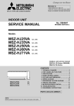
SPLIT-TYPE AIR CONDITIONERS
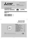
OUTDOOR UNIT
SERVICE MANUAL
HFC
utilized
No. OBH502
REVISED EDITION-C
R410A
Models
MUZ-D30NA / - / - / MUZ-D36NA / - / - / MUY-D30NA / MUY-D36NA / 1
U1
U2
1
U1
U2
1
1
Indoor unit service manual
MSZ-D•NA Series (OBH501)
MSY-D•NA Series (OBH501)
CONTENTS
1. TECHNICAL CHANGES ··································· 3
2. PART NAMES AND FUNCTIONS ····················· 3
3. SPECIFICATION ················································ 4
4. OUTLINES AND DIMENSIONS ························ 6
5. WIRING DIAGRAM············································ 7
6. REFRIGERANT SYSTEM DIAGRAM ··············11
7. DATA ································································ 13
8. ACTUATOR CONTROL ··································· 20
9. SERVICE FUNCTIONS ··································· 21
10. TROUBLESHOOTING ····································· 22
11. DISASSEMBLY INSTRUCTIONS ···················· 41
PARTS CATALOG (OBB502)
TM
NOTE:
RoHS compliant products have <G> mark on the spec name plate.
Use the specified refrigerant only
Never use any refrigerant other than that specified.
Doing so may cause a burst, an explosion, or fire when the unit is being used, serviced, or disposed of.
Correct refrigerant is specified in the manuals and on the spec labels provided with our products.
We will not be held responsible for mechanical failure, system malfunction, unit breakdown or accidents caused by
failure to follow the instructions.
Revision A:
• 3. SPECIFICATION has been corrected.
Revision B:
• MUZ-D•NA- 1 /- U2 and MUY-D•NA- 1 have been corrected.
Revision C:
• Errors in TROUBLESHOOTING have been corrected.
2
1
TECHNICAL CHANGES
MUZ-D30NA MUZ-D30NA- U1
MUZ-D36NA MUZ-D36NA- U1
MUY-D30NA
MUY-D36NA
1. New model
MUZ-D30NA →
MUZ-D36NA →
MUY-D30NA →
MUY-D36NA →
MUZ-D30NAMUZ-D36NAMUY-D30NAMUY-D36NA-
1
1
MUZ-D30NA- U1 → MUZ-D30NA- U2
MUZ-D36NA- U1 → MUZ-D36NA- U2
1
1
1. Wiring diagram has been changed.
2. Fan motor has been changed.
2
PART NAMES AND FUNCTIONS
MUZ-D30NA MUZ-D36NA MUY-D30NA MUY-D36NA
Air inlet
(back and side)
Piping
Drain hose
Air outlet
Drain outlet
3
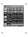
3
SPECIFICATION
Item
Capacity
Rated (Minimum ~
Maximum)
Capacity
Model
Cooling 1
Btu/h
Heating 47 1
Heating 17 2
Btu/h
Power consumption Cooling 1
Rated (Minimum ~
Maximum)
(TOTAL)
W
Heating 47 1
Power consumption Heating 17 2
W
EER 1 [SEER] 3 Cooling
HSPF IV(V) 4
Heating
COP
Heating 1
Outdoor unit model
Power supply
V , phase , Hz
Max. fuse size (time delay)
A
Min. circuit ampacity
A
Fan motor
F.L.A
Model
R.L.A
Compressor
L.R.A
Refrigeration oil cc
Refrigerant control
Cooling
Sound level 1
dB(A)
Heating
Defrost method
W
Dimensions
D
in.
H
Weight
Ib.
External finish
Remote controller
Control voltage (by built-in transformer)
Refrigerant piping
Refrigerant pipe size Liquid
in.
(Min. wall thickness)
Gas
Indoor
Connection method
Outdoor
Height
Between the indoor difference
ft.
& outdoor units
Piping length
Refrigerant charge (R410A)
MSZ-D30NA
MSY-D30NA
30,700
(9,800 ~ 30,700)
32,600
(8,700 ~ 34,000)
20,800
3,850
(620 ~ 3,850)
3,360
(520 ~ 3,600)
2,620
8.0 [14.5]
8.2 (6.7)
2.84
MUZ-D30NA
55
57
Reverse cycle
141
MSZ-D36NA
32,000/33,200
30,700
~ 32,000) /
(9,800 ~ 30,700) (9,800
(9,800 ~ 33,200)
35,200
—
(8,700 ~ 36,000)
—
22,800
4,140/4,360
3,380
(620 ~ 4,140) /
(620 ~ 3,380)
(620 ~ 4,360)
3,840
—
(520 ~ 4,100)
—
3,000
7.7/7.6
9.1 [16.0]
[14.5]
—
8.2 (6.7)
—
2.69
MUY-D30NA
MUZ-D36NA
208/230 , 1 , 60
25
21
0.93
TNB220FMCHT
16
20
870 (NEO22)
Linear expansion valve
55
56
—
57
—
Reverse cycle
33-1/16
13
33-7/16
126
141
Munsell 3Y 7.8/1.1
Wireless type
12 - 24 VDC
Not supplied
3/8 (0.0315)
5/8 (0.0394)
MSY-D36NA
33,200/34,600
(9,800 ~ 33,200) /
(9,800 ~ 34,600)
—
—
4,210/4,240
(620 ~ 4,210) /
(620 ~ 4,240)
—
—
7.9/8.2
[15.1]
—
—
MUY-D36NA
56
—
—
126
Flared
50
100
4 lb. 10 oz.
4 lb.
NOTE: Test conditions are based on ARI 210/240.
1: Rating conditions (Cooling) — Indoor: 80˚FDB, 67˚FWB, Outdoor: 95˚FDB, (75˚FWB)
(Heating) — Indoor: 70˚FDB, 60˚FWB, Outdoor: 47˚FDB, 43˚FWB
2:
(Heating) — Indoor: 70˚FDB, 60˚FWB, Outdoor: 17˚FDB, 15˚FWB
4
4 lb. 10 oz.
Rated frequency
Rated frequency
Maximum frequency
4 lb.
Test condition
3, 4
ARI
Mode
Indoor air condition (°F)
Dry bulb
Wet bulb
Test
Outdoor air condition (°F)
Dry bulb
Wet bulb
"A" Cooling Steady State
at rated compressor Speed
80
67
95
(75)
"B-2" Cooling Steady State
at rated compressor Speed
80
67
82
(65)
80
67
82
(65)
Low ambient Cooling Steady State
at minimum compressor Speed
80
67
67
(53.5)
Intermediate Cooling Steady State
at Intermediate compressor Speed 5
80
67
87
(69)
Standard Rating-Heating
at rated compressor Speed
70
60
47
43
Low temperature Heating
at rated compressor Speed
70
60
17
15
70
60
62
56.5
70
60
47
43
Frost Accumulation
at rated compressor Speed
70
60
35
33
Frost Accumulation
at Intermediate compressor Speed 5
70
60
35
33
SEER "B-1" Cooling Steady State
(Cooling) at minimum compressor Speed
Max temperature Heating
at minimum compressor Speed
HSPF
(Heating) High temperature Heating
at minimum compressor Speed
5: At Intermediate compressor Speed
=("Cooling rated compressor speed" - "minimum compressor speed") / 3 + "minimum compressor speed".
OPERATING RANGE
(1) POWER SUPPLY
Rated voltage
Outdoor unit
Guaranteed voltage (V)
208/230 V
1 phase
60 Hz
Min. 187
208
230
Max. 253
(2) OPERATION
Intake air temperature (°F)
Mode
Condition
Standard temperature
Maximum temperature
Cooling
Minimum temperature
Maximum humidity
Standard temperature
Heating Maximum temperature
Minimum temperature
Indoor
Outdoor
DB
80
90
67
WB
67
73
57
DB
95
115
14
60
67
60
47
75
14
78%
WB
—
—
—
—
70
80
70
5
43
65
13
4
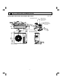
OUTLINES AND DIMENSIONS
MUZ-D30NA MUZ-D36NA MUY-D30NA MUY-D36NA
REQUIRED SPACE
4 in
. or
Unit: inch
Open as a rule
20 inch or more if
the front and both
sides are open
4 inch or more /
8 inch or more if
there are obstacles
to both sides
mo
re
14
Open as a rule
20 inch or more if the back,
both sides and top are open
6
in.
or m
ore
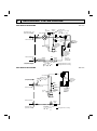
5
WIRING DIAGRAM
MUZ-D30NA MUZ-D30NA- U1 MUZ-D36NA MUZ-D36NA- U1
7
MUZ-D30NA-
1
MUZ-D30NA- U2 MUZ-D36NA-
8
1
MUZ-D36NA- U2
MUY-D30NA MUY-D36NA
9
MUY-D30NA-
1
MUY-D36NA-
1
10
6
REFRIGERANT SYSTEM DIAGRAM
MUZ-D30NA MUZ-D36NA
Unit: inch
Oil
separator
Refrigerant pipe 5/8
(with heat insulator)
Capillary tube
O.D. 0.071 x I.D. 0.024
x 39-3/8
( 1.8 x 0.6 x 1,000)
Strainer
#100
4-way valve
Service
port
Stop valve
(with service port)
Outdoor
Defrost
heat
High-pressure thermistor exchanger
Switch
RT61
Flared connection
Discharge
temperature
thermistor
RT62
Service
port
Outdoor heat
exchanger
temperature
thermistor
RT68
Compressor
Flared connection
LEV
Strainer
Receiver #100
Stop valve
Strainer
#100
R.V. coil
heating ON
cooling OFF
Capillary tube
O.D. 0.142 I.D. 0.094
1-31/32
2.4 50)
( 3.6
Refrigerant pipe 3/8
(with heat insulator)
Ambient
temperature
thermistor
RT65
Refrigerant flow in cooling
Refrigerant flow in heating
Unit: inch
MUY-D30NA MUY-D36NA
Oil separator
Refrigerant pipe 5/8
(with heat insulator)
Flared connection
Outdoor
heat
exchanger
Capillary tube
O.D. 0.071 x I.D. 0.024
x 39-3/8
( 1.8 x 0.6 x 1,000)
Strainer
#100
Service
port
High-pressure
Switch
Stop valve
(with service port)
Discharge
temperature
thermistor
RT62
Service
port
Outdoor heat
exchanger
temperature
thermistor
RT68
Compressor
Flared connection
LEV
Stop valve
Refrigerant pipe 3/8
(with heat insulator)
Strainer
#100
Capillary tube
O.D. 0.142 x I.D. 0.094
x 1-31/32
( 3.6 x 2.4 x 50)
11
Refrigerant flow in cooling
Ambient
temperature
thermistor
RT65
MAX. REFRIGERANT PIPING LENGTH and MAX. HEIGHT DIFFERENCE
Model
Refrigerant piping: ft.
Max. Length
Max. Height difference
A
B
MUZ-D30NA
MUZ-D36NA
MUY-D30NA
MUY-D36NA
100
Piping size O.D: in.
50
Gas
Liquid
5/8
3/8
Indoor
unit
Max. Height
difference
B
Max. Length
A
Outdoor unit
ADDITIONAL REFRIGERANT CHARGE (R410A: oz.)
Refrigerant piping exceeding 25 ft. requires additional refrigerant charge according to the calculation.
Refrigerant piping length (one way): ft.
50
60
70
80
Model
Outdoor unit
precharged
25
30
40
MUZ-D30NA
MUZ-D36NA
4 lb. 10 oz.
0
2.96
8.88
14.80
20.72
26.64
32.56
90
100
38.48
44.40
Calculation: X oz. = 2.96/5 oz. / ft. × (Refrigerant piping length (ft.) - 25)
Refrigerant piping length (one way): ft.
50
60
70
80
Model
Outdoor unit
precharged
25
30
40
MUY-D30NA
MUY-D36NA
4 lb.
0
1.08
3.24
5.40
7.56
9.72
11.88
90
100
14.04
16.20
Calculation: X oz. = 1.08/5 oz. / ft. × (Refrigerant piping length (ft.) - 25)
NOTE: Refrigerant piping exceeding 25 ft. requires additional refrigerant charge according to the calculation.
12
7
DATA
MUZ-D30NA MUZ-D36NA MUY-D30NA MUY-D36NA
7-1. PERFORMANCE DATA
1) COOLING CAPACITY
Indoor air
Model
MUZ-D30NA
MUZ-D36NA
MUY-D30NA
MUY-D36NA
(208 V)
MUY-D36NA
(230 V)
IWB (˚F)
71
67
63
71
67
63
71
67
63
71
67
63
71
67
63
TC
37.6
35.6
33.5
40.7
38.5
36.2
37.6
35.6
33.5
40.7
38.5
36.2
42.4
40.1
37.7
75
SHC
19.1
22.8
25.9
19.8
23.9
27.3
19.1
22.8
25.9
19.8
23.9
27.3
20.6
24.9
28.4
TPC
3.43
3.23
3.08
3.88
3.66
3.49
3.01
2.84
2.70
3.75
3.54
3.37
3.77
3.56
3.39
85
SHC
17.8
21.2
24.0
18.5
22.2
25.3
17.8
21.2
24.0
18.5
22.2
25.3
19.3
23.2
26.3
TC
35.2
33.2
31.0
38.0
35.9
33.5
35.2
33.2
31.0
38.0
35.9
33.5
39.6
37.4
34.9
Outdoor intake air DB temperature (˚F)
95
105
TPC
TC
SHC TPC
TC
SHC
3.75 33.0 16.7 4.04 30.7 15.6
3.56 30.7 19.6 3.85 28.6 18.3
3.41 28.9 22.3 3.68 26.2 20.3
4.25 35.7 17.4 4.58 33.2 16.2
4.03 33.2 20.6 4.36 30.9 19.1
3.86 31.2 23.5 4.16 28.4 21.4
3.30 33.0 16.7 3.55 30.7 15.6
3.13 30.7 19.6 3.38 28.6 18.3
2.99 28.9 22.3 3.23 26.2 20.3
4.10 35.7 17.4 4.42 33.2 16.2
3.89 33.2 20.6 4.21 30.9 19.1
3.73 31.2 23.5 4.02 28.4 21.4
4.13 37.2 18.1 4.45 34.6 16.8
3.92 34.6 21.5 4.24 32.2 20.0
3.75 32.5 24.5 4.05 29.6 22.3
TPC
4.25
4.08
3.93
4.82
4.62
4.45
3.73
3.58
3.45
4.65
4.46
4.29
4.69
4.49
4.32
TC
28.2
26.2
23.9
30.5
28.4
25.9
28.2
26.2
23.9
30.5
28.4
25.9
31.8
29.6
27.0
115
SHC
14.3
16.8
18.5
14.9
17.6
19.5
14.3
16.8
18.5
14.9
17.6
19.5
15.5
18.3
20.3
TPC
4.43
4.27
4.08
5.01
4.84
4.62
3.89
3.75
3.58
4.84
4.67
4.46
4.88
4.71
4.49
NOTE: 1. IWB : Intake air wet-bulb temperature
TC : Total Capacity (x103 Btu/h)
SHC : Sensible Heat Capacity (x103 Btu/h)
TPC : Total Power Consumption (kW)
2. SHC is based on 80˚F of indoor Intake air DB temperature.
2) COOLING CAPACITY CORRECTIONS
Refrigerant piping length (one way: ft.)
25 (std.)
40
65
MUZ-D30NA
MUZ-D36NA
MUY-D30NA
MUY-D36NA
1.0
0.95
100
0.878
0.713
3) HEATING CAPACITY
Indoor air
Model
MUZ-D30NA
MUZ-D36NA
IDB (˚F)
75
70
65
75
70
65
15
TC
18.9
20.0
20.5
20.4
21.6
22.2
25
TPC
2.50
2.42
2.32
2.86
2.76
2.65
TC
23.6
24.5
25.6
25.5
26.4
27.6
Outdoor intake air WB temperature (˚F)
35
43
45
TPC
TC
TPC
TC
TPC
TC
TPC
2.94
28.2
3.28
31.8
3.44
32.8
3.49
2.87
28.9
3.19
32.6
3.36
33.6
3.43
2.77
29.8
3.11
33.6
3.28
34.6
3.33
3.36
30.4
3.74
34.3
3.94
35.4
3.99
3.28
31.2
3.65
35.2
3.84
36.3
3.92
3.17
32.2
3.55
36.3
3.74
37.3
3.80
55
TC
37.2
38.0
38.8
40.1
41.0
41.9
TPC
3.63
3.56
3.49
4.15
4.07
3.99
NOTE: 1. IDB : Intake air dry-bulb temperature
3
TC : Total Capacity (x10 Btu/h)
TPC : Total Power Consumption (kW)
2. Above data is for heating operation without any frost.
How to operate with fixed operational frequency of the compressor.
1. Press the EMERGENCY OPERATION switch on the front of the indoor unit, and select either EMERGENCY COOL
mode or EMERGENCY HEAT mode before starting to operate the air conditioner.
2. The compressor starts with operational frequency.
3. The fan speed of the indoor unit is High.
4. This operation continues for 30 minutes.
5. In order to release this operation, press the EMERGENCY OPERATION switch twice or once, or press any button on
the remote controller.
13
65
or in
take
air W
B te
mpe
ratu
or
Indo
re (°
F)
(°F)
ture
pera
tem
WB
e air
k
ta
in
75
85
95
105
Outdoor intake air DB temperature (°F)
71
67
63
71
67
63
115
SHF at rating condition = 0.62
Airflow = 763 CFM
43
41
39
37
35
33
31
29
27
Indo
or in
take
air W
B te
mpe
ratu
5.2
4.8
4.4
or
Indo
4.0
re (°
F)
ture
pera
tem
WB
e air
k
ta
in
(°F)
71
67
63
71
67
63
3.6
65
75
85
95
105
Outdoor intake air DB temperature (°F)
115
Total capacity
( 103 Btu/h)
Indo
MUY-D30NA
Total power consumption
(kW)
4.5
4.3
4.1
3.9
3.7
3.5
3.3
3.1
SHF at rating condition = 0.64
Airflow = 763 CFM
Total capacity
( 103 Btu/h)
40
38
36
34
32
30
28
26
24
MUZ-D36NA
Total power consumption
(kW)
Total power consumption
(kW)
Total capacity
( 103 Btu/h)
7-2. PERFORMANCE CURVE
Cooling
MUZ-D30NA
40
38
36
34
32
30
28
26
24
4.0
3.8
3.6
3.4
3.2
3.0
2.8
2.6
65
SHF at rating condition = 0.64
Airflow = 763 CFM
Indo
or in
take
air W
B te
mpe
ratu
re (°
F)
75
85
95
105
Outdoor intake air DB temperature (°F)
MUY-D36NA
46
SHF at rating condition = 0.62
Airflow = 763 CFM
Total capacity
( 103 Btu/h)
42
38
34
Indo
or in
take
a
ir W
B te
30
mpe
rature
Total power consumption
(kW)
26
5.0
3.8
F)
re (°
ratu
mpe
B te
4.6
4.2
(°F)
71
67
63
71
67
63
ta
or in
Indo
ir W
ke a
3.4
65
75
85
95
105
Outdoor intake air DB temperature (°F)
115
Heating
MUZ-D36NA
MUZ-D30NA
Airflow = 848 CFM
Total power consumption
(kW)
Total capacity
( 103 Btu/h)
35
30
25
B
air D
take
or in
Indo
15
3.6
3.2
ke air
r inta
Indoo
F)
ture (°
mpera
DB te
2.8
2.4
15
25
35
43
38
20
4.0
45
Airflow = 848 CFM
48
65
70
75
F)
e (°
atur
per
tem
Total capacity
( 103 Btu/h)
40
55
Outdoor intake air WB temperature (°F)
75
70
65
Total power consumption
(kW)
45
33
28
oor
Ind
(°
ture
era
mp
B te
D
ir
ke a
inta
65
70
75
F)
23
18
4.5
3.7
ture
pera
4.1
or
Indo
m
DB te
e air
intak
(°F)
75
70
65
3.3
2.9
15
25
35
45
55
Outdoor intake air WB temperature (°F)
This value of frequency is not the same as the actual frequency in operating. Refer to 7-5 and 7-6 for the relationships
between frequency and capacity.
14
71
67
63
k
r inta
o
Indo
F)
re (°
ratu
mpe
B te
W
e air
71
67
63
115
7-3. CONDENSING PRESSURE
Cooling
Data is based on the condition of indoor humidity 50%.
Air flow should be set to High speed.
MUZ-D30NA
(PSIG)
580
86
80
75
70
Condensing pressure
540
500
a
per
B
rD
tem
)
(°F
140
doo
420
In
(PSIG)
150
Suction pressure
460
e
tur
380
340
86
80
130
75
120
70
110
100
300
260
68 70
re (°F)
temperatu
Indoor DB
75
80
85
90
95
100
90
68 70
105(°F)
Outdoor ambient temperature
75
80
85
90
95
Outdoor ambient temperature
100
105(°F)
MUZ-D36NA
(PSIG)
580
86
80
75
70
500
460
420
°F)
e(
(PSIG)
150
pe
em
t
DB
or
o
d
In
ur
rat
140
Suction pressure
Condensing pressure
540
380
340
Indoor DB
re (°F)
86
temperatu
80
120
75
70
110
100
300
260
68 70
130
75
80
85
90
95
100
90
68 70
105(°F)
Outdoor ambient temperature
75
80
85
90
95
Outdoor ambient temperature
100
105(°F)
MUY-D30NA
(PSIG)
580
500
oor
420
Ind
DB
per
tem
)
°F
e(
r
atu
460
86
80
75
70
140
380
340
re (°F)
temperatu
Indoor DB
86
80
130
75
120
70
110
100
300
260
68 70
(PSIG)
150
Suction pressure
Condensing pressure
540
75
80
85
90
95
100
90
68 70
105(°F)
Outdoor ambient temperature
15
75
80
85
90
95
Outdoor ambient temperature
100
105(°F)
MUY-D36NA
(PSIG)
580
Condensing pressure
540
r
atu
per
500
em
Bt
(PSIG)
150
D
oor
Ind
140
Suction pressure
460
86
80
75
70
)
°F
e(
420
380
340
re (°F)
temperatu
Indoor DB
130
86
80
120
75
110
70
100
300
260
68 70
75
80
85
90
95
100
90
68 70
105(°F)
75
80
85
90
95
Outdoor ambient temperature
Outdoor ambient temperature
Heating
Data is based on the condition of outdoor humidity 75%.
Air flow should be set to High speed.
Data is for heating operation without any frost.
MUZ-D30NA
(PSIG)
500
(PSIG)
150
480
75
440
400
380
oor
Ind
re
atu
per
em
t
DB
58Hz
300
120
65
340
320
130
70
)
(°F
Suction pressure
Condensing pressure
420
360
280
)
110
r
pe
m
100
90
or
do
In
80
DB
re
u
at
(°F
te
58Hz
70
260
240
60
220
200
14
75
70
65
140
460
50
14
20 25 30 35 40 45 50 55 60 65 70(°F)
20
25
30
35
40
45
50
55
60
65 70(°F)
Outdoor ambient temperature
Outdoor ambient temperature
MUZ-D36NA
(PSIG)
500
(PSIG)
150
480
140
460
75
Condensing pressure
400
360
°F)
re(
420
300
58Hz
110
100
DB
or
do
n
I
90
re
tu
ra
pe
m
te
)
(°F
80
280
58Hz
70
260
240
60
220
200
14
120
65
340
320
130
70
p
em
Bt
rD
oo
Ind
tu
era
Suction pressure
440
380
75
70
65
20 25 30 35 40 45 50 55 60 65 70(°F)
50
14
20
25
30
35
40
45
50
55
Outdoor ambient temperature
Outdoor ambient temperature
16
60
65 70(°F)
100
105(°F)
7-4. STANDARD OPERATION DATA
Model
MSZ-D30NA
Item
Total
Capacity
MSY-D30NA
MSY-D36NA
Unit
Cooling
Heating
Cooling
Heating
Cooling
Cooling
Btu/h
30,700
32,600
32,000/33,200
35,200
30,700
33,200/34,000
SHF
—
0.64
—
0.62
—
0.64
0.62
Input
kW
3.85
3.36
4.14/4.36
3.84
3.38
4.21/4.24
Rated frequency
Hz
84
84
91
91
79
92
MSY-D30NA
MSY-D36NA
MUY-D30NA
MUY-D36NA
Indoor unit
MSZ-D30NA
Electrical circuit
Power supply
Input
Fan motor current
Refrigerant circuit
208/230 , 1 , 60
kW
0.058
A
0.45/0.42
MUZ-D30NA
MUZ-D36NA
V,
phase,
Hz
Power supply
208/230 , 1 , 60
kW
3.792
3.302
4.082/4.302
3.782
3.322
4.152/4.182
Comp. current
A
17.25/15.56
14.95/13.46
18.65/17.86
17.25/15.56
15.05/13.56
18.95/17.26
Fan motor current
A
0.80/0.72
Condensing pressure
PSIG
468
404
480
420
453
475
Suction pressure
PSIG
126
96
122
94
125
119
Discharge temperature
˚F
186.8
169.7
198.7
168.8
191.3
197.1
Condensing temperature
˚F
126.5
114.3
128.5
117.0
123.8
127.4
Suction temperature
˚F
45.5
29.8
48.0
29.1
54.7
48.6
Comp. shell bottom temperature
˚F
175.6
156.4
187.0
155.7
177.4
182.7
Ref. pipe length
ft.
Refrigerant charge (R410A)
—
Intake air temperature
Indoor unit
MSZ-D36NA
V,
phase,
Hz
Outdoor unit
Input
Discharge air temperature
WB
˚F
67
60
67
60
67
67
DB
˚F
53.9
112.2
53
114.9
53.7
51.7
˚F
53
73.9
52.1
74.6
52.8
50.8
WB
80
70
4 lb.
˚F
Fan speed (High)
Intake air temperature
25
4 lb. 10 oz.
DB
80
rpm
Airflow (High)
Outdoor unit
MSZ-D36NA
DB
WB
70
80
80
1,100
CFM
741 (Wet)
795
738 (Wet)
794
718 (Wet)
710 (Wet)
˚F
95
47
95
47
95
95
˚F
—
43
—
43
—
—
Fan speed
rpm
800
Airflow
CFM
1,941
17
7-5. CAPACITY AND INPUT CORRECTION BY INVERTER OUTPUT FREQUENCY
MUZ-D30NA
Correction of Cooling total input
0.5
50
100
Capacity correction factors
Input correction factors
Capacity correction factors
1.0
0
1.5
1.5
1.0
0.5
150 (Hz)
0
50
100
Correction of Heating capacity
1.0
0.5
0
150 (Hz)
1.5
Input correction factors
Correction of Cooling capacity
1.5
50
100
150 (Hz)
The operational frequency of compressor The operational frequency of compressor The operational frequency of compressor
Correction of Heating total input
1.0
0.5
0
50
100
150 (Hz)
The operational frequency of compressor
MUZ-D36NA
Correction of Cooling total input
1.0
0.5
0
50
100
150 (Hz)
Capacity correction factors
Input correction factors
Capacity correction factors
1.5
1.5
1.0
0.5
0
50
100
150 (Hz)
Correction of Heating capacity
1.0
0.5
0
1.5
Input correction factors
Correction of Cooling capacity
1.5
50
100
150 (Hz)
The operational frequency of compressor The operational frequency of compressor The operational frequency of compressor
MUY-D30NA
Correction of Cooling capacity
Correction of Cooling total input
1.5
Input correction factors
Capacity correction factors
1.5
1.0
0.5
0
50
100
1.0
0.5
150 (Hz)
0
50
100
150
The operational frequency of compressor The operational frequency of compressor
MUY-D36NA
Correction of Cooling capacity
Correction of Cooling total input
1.5
Input correction factors
Capacity correction factors
1.5
1.0
0.5
0
50
100
150 (Hz)
1.0
0.5
0
50
100
150
The operational frequency of compressor The operational frequency of compressor
18
Correction of Heating total input
1.0
0.5
0
50
100
150 (Hz)
The operational frequency of compressor
7-6. TEST RUN OPERATION (How to operate fixed-frequency operation)
1. Press EMERGENCY OPERATION switch to COOL or HEAT mode (COOL: Press once, HEAT: Press twice).
2. Test run operation starts and continues to operate for 30 minutes.
3. Compressor operates at rated frequency in COOL mode or 58 Hz in HEAT mode.
4. Indoor fan operates at High speed.
5. After 30 minutes, test run operation finishes and EMERGENCY OPERATION starts (Operation frequency of compressor
varies).
6. To cancel test run operation (EMERGENCY OPERATION), press EMERGENCY OPERATION switch or any button on
remote controller.
19
8
ACTUATOR CONTROL
MUZ-D30NA MUZ-D36NA MUY-D30NA MUY-D36NA
8-1. OUTDOOR FAN MOTOR CONTROL
The fan motor turns ON/OFF, interlocking with the compressor.
[ON] The fan motor turns ON 5 seconds before the compressor starts up.
[OFF] The fan motor turns OFF 15 seconds after the compressor has stopped running.
5 seconds
15 seconds
ON
Compressor
OFF
ON
Outdoor fan
motor
OFF
8-2. R.V. COIL CONTROL
<MUZ>
Heating . . . . . . . . . . . . . . . . . ON
Cooling . . . . . . . . . . . . . . . . . OFF
Dry . . . . . . . . . . . . . . . . . . . . OFF
NOTE: The 4-way valve reverses for 5 seconds right before start-up of the compressor.
<COOL>
<HEAT>
5 seconds
5 seconds
R.V.coil
ON
OFF
ON or OFF
ON or OFF
Outdoor fan ON
OFF
motor
8-3. Relation between main sensor and actuator
Sensor
Discharge temperature thermistor
Indoor coil temperature thermistor
Defrost thermistor
Fin temperature thermistor
Outdoor heat exchanger temperature
Ambient temperature thermistor
Purpose
Compressor
Protection
Cooling: Coil frost prevention
Heating: High pressure protection
Defrosting
Protection
Protection
Cooling: Low ambient temperature operation
20
○
○
○
○
○
○
○
LEV
○
○
○
○
○
Actuator
Outdoor
fan motor
○
○
○
○
○
R.V. coil
Indoor
fan motor
○
○
9
SERVICE FUNCTIONS
MUZ-D30NA MUZ-D36NA MUY-D30NA MUY-D36NA
9-1. PRE-HEAT CONTROL
If moisture gets into the refrigerant cycle, or when refrigerant is liquefied and collected in the compressor, it may interfere the start-up of the compressor.
To improve start-up condition, the compressor is energized even while it is not
operating.
This is to generate heat at the winding.
The compressor uses about 50 W when pre-heat control is turned ON.
Pre-heat control is OFF at initial setting.
ON
1
2
3
4
3
4
[How to activate pre-heat control]
1. Turn OFF the power supply for the air conditioner before making the setting.
2. Set the 2nd Dip Switch of SW1 on the outdoor electronic control P.C. board to
ON to activate pre-heat control function.
9-2. CHANGE IN DEFROST SETTING
Changing defrost finish temperature
1. Turn OFF the power supply for the air conditioner before making the setting.
2. Set the 4th Dip Switch of SW1 on the outdoor electronic control P.C. board to
ON to change the defrost finish temperature. (Refer to 10-6-1.)
ON
1
4th Dip Switch of SW1
Defrost finish temperature
OFF
(Initial setting)
49.5°F (9.7°C)
ON
64.9°F (18.3°C)
21
2
10
TROUBLESHOOTING
MUZ-D30NA MUZ-D36NA MUY-D30NA MUY-D36NA
10-1. CAUTIONS ON TROUBLESHOOTING
1. Before troubleshooting, check the following
1) Check the power supply voltage.
2) Check the indoor/outdoor connecting wire for miswiring.
2. Take care of the following during servicing
1) Before servicing the air conditioner, be sure to turn OFF the main unit first with the remote controller, and after confirming the horizontal vane is closed, turn off the breaker and/or disconnect the power plug.
2) Be sure to turn OFF the power supply before removing the front panel, the cabinet, the top panel, and the electronic
control P.C. board.
3) When removing the electrical parts, be careful of the residual voltage of smoothing capacitor.
4) When removing the electronic control P.C. board, hold the edge of the board with care NOT to apply stress on the
components.
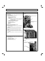
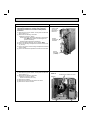
5) When connecting or disconnecting the connectors, hold the housing of the connector. DO NOT pull the lead wires.
Incorrect
Correct
Lead wiring
Housing point
3. Troubleshooting procedure
1) First, check if the OPERATION INDICATOR lamp on the indoor unit is flashing on and off to indicate an abnormality.
To make sure, check how many times the OPERATION INDICATOR lamp is flashing on and off before starting service work.
2) Before servicing check that the connector and terminal are connected properly.
3) When the electronic control P.C. board seems to be defective, check the copper foil pattern for disconnection and the
components for bursting and discoloration.
4) Refer to 10-2 and 10-3.
22
10-2. FAILURE MODE RECALL FUNCTION
Outline of the function
This air conditioner can memorize the abnormal condition which has occurred once.
Even though LED indication listed on the troubleshooting check table (10-3.) disappears, the memorized failure details
can be recalled.
This mode is very useful when the unit needs to be repaired for the abnormality which does not recur.
This figures show about MSZ type.
1. Flow chart of failure mode recall function for the indoor/outdoor unit
Operational procedure
The cause of abnormality cannot be found because the abnormality does not recur.
Setting up the failure mode recall function
Turn ON the power supply.
<Preparation of the remote controller>
While pressing both OPERATION SELECT button and TOO COOL button on the
remote controller at the same time, press RESET button.
First, release RESET button.
Hold down the other two buttons for another 3 seconds. Confirm that the indicators on
the LCD screen shown in the right figure are all displayed. Then release the buttons.
Press OPERATE/STOP (ON/OFF) button of the remote controller (the set temperature
is displayed) with the remote controller headed towards the indoor unit. 1
1. Regardless of normal or abnormal condition, a short
beep is emitted once the signal is received.
Does the left lamp of OPERATION INDICATOR lamp on the
indoor unit blink at the interval of 0.5 seconds?
Blinks: Either indoor or outdoor unit is abnormal. Beep is emitted at the same timing as the blinking of the left lamp
of OPERATION INDICATOR lamp. 2
Judgment of indoor/outdoor abnormality
No
(OFF)
Indoor unit is normal.
But the outdoor unit might be abnormal because there are some abnormalities that cannot be recalled with this way.
Confirm if outdoor unit is abnormal according to the detailed outdoor
unit failure mode recall function. (Refer to 10-2.2)
Yes
(Blinks)
Before blinking, does the left lamp of OPERATION INDICATOR lamp stay ON for 3 seconds?
Stays ON for 3 seconds (without beep):
The outdoor unit is abnormal.
No
Yes
The indoor unit is abnormal.
Check the blinking pattern, and confirm the abnormal point with the indoor unit
failure mode table. (Refer to indoor unit service manual.)
Make sure to check at least two consecutive blinking cycles. 2
The outdoor unit is abnormal.
Check the blinking pattern, and confirm the abnormal point with the
outdoor unit failure mode table. (Refer to 10-2.3)
Make sure to check at least two consecutive blinking cycles. 3
Releasing the failure mode recall function
Release the failure mode recall function by the following procedures.
Turn OFF the power supply and turn it ON again.
Press RESET button of the remote controller.
Repair the defective parts.
Deleting the memorized abnormal condition
After repairing the unit, recall the failure mode again according to "Setting up the failure mode recall
function" mentioned above.
Press OPERATE/STOP (ON/OFF) button of the remote controller (the set temperature is displayed)
with the remote controller headed towards the indoor unit.
Press EMERGENCY OPERATION switch so that the memorized abnormal condition is deleted.
Release the failure mode recall function according to "Releasing the failure mode recall function"
mentioned above.
NOTE: 1. Make sure to release the failure mode recall function once it is set up, otherwise the unit cannot operate properly.
2. If the abnormal condition is not deleted from the memory, the last abnormal condition is kept memorized.
2. Blinking pattern when the indoor unit is abnormal:
Blinking at 0.52.5-second OFF second interval
Blinking at 0.52.5-second OFF second interval
ON
OFF
Beeps
Repeated cycle
Beeps
Repeated cycle
3.Blinking pattern when the outdoor unit is abnormal:
Blinking at 0.52.5-second OFF
3-second ON
second interval
Beeps
Repeated cycle
2.5-second OFF
3-second ON
Blinking at 0.5second interval
ON
OFF
No beep
Repeated cycle
Beeps
No beep
Repeated cycle
23
Beeps
Repeated cycle
2. Flow chart of the detailed outdoor unit failure mode recall function
Operational procedure
The outdoor unit might be abnormal.
Confirm if outdoor unit is abnormal according to the following procedures.
Confirm that the remote controller is in the failure mode recall function.
With the remote controller headed towards the indoor unit, press TOO
COOL or TOO WARM button to adjust the set temperature to 77˚F (25˚C).
1
Does left lamp of OPERATION INDICATOR lamp on
the indoor unit blink at the interval of 0.5 seconds?
Blinks: The outdoor unit is abnormal. Beep is emitted
at the same timing as the blinking of the left
lamp of OPERATION INDICATOR lamp. 2
1. Regardless of normal or abnormal condition, 2 short
beeps are emitted as the signal is received.
No
(OFF)
Yes
(Blinks)
The outdoor unit is abnormal.
Check the blinking pattern, and confirm the abnormal point with the outdoor unit failure mode table. (10-2.3.)
Make sure to check at least two consecutive blinking cycles. 2
The outdoor unit is normal.
Releasing the failure mode recall function
Release the failure mode recall function by the following procedures.
Turn OFF the power supply and turn it ON again.
Press RESET button of the remote controller.
Release the failure mode recall function according to the left mentioned procedure.
Repair the defective parts.
Deleting the memorized abnormal condition
After repairing the unit, recall the failure mode again according to "Setting up the failure mode recall
function" (10-2.1.).
Press OPERATE/STOP (ON/OFF) button of the remote controller (the set temperature is displayed)
with the remote controller headed towards the indoor unit.
Press EMERGENCY OPERATION switch so that the memorized abnormal condition is deleted.
Release the failure mode recall function according to "Releasing the failure mode recall function"
mentioned above.
NOTE: 1. Make sure to release the failure mode recall function once it is set up, otherwise the unit cannot operate properly.
2. If the abnormal condition is not deleted from the memory, the last abnormal condition is kept memorized.
2.Blinking pattern when outdoor unit is abnormal:
2.5-second OFF
ON
OFF
3-second ON
No beep
Repeated cycle
Blinking at 0.5second interval
2.5-second OFF
Beeps
3-second ON
No beep
Repeated cycle
24
Blinking at 0.5second interval
Beeps
Repeated cycle
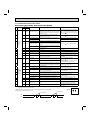
3. Outdoor unit failure mode table
MUZ-D30NA MUZ-D36NA MUY-D30NA MUY-D36NA
The left lamp of OPERATION INDICATOR lamp
(Indoor unit)
OFF
2-time flash
Abnormal point
(Failure mode / protection)
Non (Normal)
LED indication
(Outdoor P.C.
board)
Condition
Remedy
Indoor/outdoor
unit failure mode
recall function
LED 1
LED 2
Lighting
Lighting
—
—
—
IPM protection stop or lock protection stop is continuously
performed 3 times within 1 minute after the compressor gets started, or converter protection stop or bus-bar
voltage protection stop is continuously performed 3 times
within 3 minutes after start-up.
• Check the connection of the
compressor connecting wire.
• Refer to 10-5. "How to check
inverter/compressor".
• Refer to 10-5. "Check of
compressor start failure".
• Check the stop valve.
○
Outdoor power system
Lighting
Lighting
Discharge temperature thermistor
Lighting
Once
Defrost thermistor (MUZ)
Lighting
Once
Ambient temperature thermistor
Lighting
Twice
Fin temperature thermistor
Lighting
3 times
P.C. board temperature thermistor
Lighting
4 times
• Replace the outdoor electronic
control P.C. board.
Outdoor heat exchanger temperature thermistor
Lighting
9 times
• Refer to 10-5. "Check of
outdoor thermistors".
3-time flash
• Refer to 10-5. "Check of
outdoor thermistors".
○
Thermistor shorts or opens during compressor running.
• Reconnect compressor connector.
• Refer to 10-5. "How to check
inverter/compressor."
• Refer to 10-5. "Check of
compressor start failure".
• Check the stop valve.
Once
Goes
out
Discharge temperature
Lighting
Lighting
Temperature of discharge temperature thermistor exceeds • Check refrigerant circuit and
241°F (116°C), compressor stops. Compressor can restart refrigerant amount.
• Refer to 10-5. "Check of
if discharge temperature thermistor reads 212°F (100°C)
or less 3 minutes later.
LEV".
—
High pressure
Lighting
Lighting
The outdoor heat exchanger temperature exceeds 158°F
(70°C) during cooling or the indoor gas pipe temperature
exceeds 158°F (70°C) during heating (MUZ).
• Check refrigerant circuit and
refrigerant amount.
• Check the stop valve.
—
Fin temperature
3 times
Goes
out
The fin temperature exceeds 189°F (87°C) during operation.
—
P.C. board temperature
4 times
Goes
out
The P.C. board temperature exceeds 158°F (70°C) during
operation.
• Check around outdoor unit.
• Check outdoor unit air passage.
• Refer to 10-5. "Check of
outdoor fan motor".
8-time flash
Outdoor fan motor
Lighting
Lighting
Failure occurs continuously 3 times within 30 seconds
after the fan gets started.
• Refer to 10-5. "Check of
outdoor fan motor".
—
9-time flash
Nonvolatile memory data
Lighting
5 times
Nonvolatile memory data cannot be read properly.
• Replace the outdoor electronic
control P.C. board.
○
4-time flash
Overcurrent
5-time flash
6-time flash
28 A current flow into intelligent power module.
7-time flash
10-time flash
11-time flash
Discharge temperature
Lighting
Lighting
Communication error between
P.C. boards
Lighting
6 times
Current sensor
Lighting
7 times
• Check refrigerant circuit and
The frequency of the compressor is kept 80 Hz or more
amount.
and the discharge temperature is kept under 102°F (39°C) • refrigerant
Refer to 10-5. "Check of
for more than 20 minutes.
LEV".
Communication error occurs between the electronic control • Check the connecting wire
between outdoor electronic
P.C. board and power board for more than 10 seconds.
control P.C. board and power
board.
The communication between boards protection stop is
continuously performed twice.
A short or open circuit is detected in the current sensor
during compressor operating.
5 times
Goes out
The protection stop of the zero cross detecting circuit is
continuously performed 10 times.
• Check the connecting wire
among electronic control P.C.
board, noise filter P.C. board
and power board.
NOTE: Blinking patterns of this mode differ from the ones of Troubleshooting check table (10-3.).
25
—
—
○
—
○
Current sensor protection stop is continuously performed
twice.
Zero cross signal cannot be detected while the compressor is operating.
Zero cross detecting circuit
• Replace the power board.
—
—
○
The left lamp of OPERATION INDICATOR lamp
(Indoor unit)
Abnormal point
(Failure mode / protection)
LED indication (Outdoor P.C. board)
LED 1
11-time flash
Condition
5 times
failure is detected in the operation of the converter durGoes out A
ing operation.
Bus-bar voltage (1)
5 times
bus-bar voltage exceeds 400 V or falls to 200 V or
Goes out The
below during compressor operating.
6 times
Indoor/outdoor
unit failure mode
recall function
LED 2
Converter
Bus-bar voltage (2)
Even if this protection stop
is performed continuously 3
times, it does not mean the
abnormality in outdoor power
system.
Remedy
bus-bar voltage exceeds 400 V or falls to 50 V or
Goes out The
below during compressor operating.
26
• Check the voltage of
power supply.
• Replace the power board.
• Check the voltage of
power supply.
• Replace the outdoor
electronic control P.C.
board.
—
10-3. TROUBLESHOOTING CHECK TABLE
MUZ-D30NA MUZ-D36NA MUY-D30NA MUY-D36NA
No.
Indication
LED1
LED2
(Red)
(Yellow)
Symptom
1
Lightning Twice
2
Lightning 3 times
3
Lightning 4 times
4
5
Outdoor
unit does
not operate.
Lightning 5 times
Lightning 6 times
6
Lightning 7 times
7
Lightning 8 times
8
Lightning 11 times
9
Lightning 12 times
Abnormal point / Condition
Outdoor power system
Twice
Zero cross detecting circuit
Goes out
Lock protection
11
3 times
Goes out
12
4 times
Goes out
13
14
'Outdoor
unit stops 5 times
and restarts
3 minutes
8 times
later' is
repeated.
Goes out
Goes out
15
9 times
Goes out
16
13 times
Goes out
17
Lighting
8 times
18
Lighting
11 times
19
Lighting
12 times
Remedy
IPM protection stop or lock protection stop is continuously
performed three times within 1 minute after the compressor
gets started, or converter protection stop or bus-bar voltage
protection stop is continuously performed 3 times within 3
minutes after start-up.
A short circuit is detected in the thermistor during operaDischarge temperature thermtion, or an open circuit is detected in the thermistor after 10
istor
minutes of compressor start-up.
Fin temperature thermistor
A short or open circuit is detected in the thermistor during
P.C. board temperature therm- operation.
istor
Ambient temperature thermis- A short or open circuit is detected in the thermistor during
tor
operation.
A short circuit is detected in the thermistor during operation,
Outdoor heat exchanger
or an open circuit is detected in the thermistor after 5 minutes
temperature thermistor
(in cooling) and 10 minutes (in heating (MUZ)) of compressor
start-up.
A short circuit is detected in the thermistor during operation,
Defrost thermistor (MUZ)
or an open circuit is detected in the thermistor after 5 minutes
of compressor start-up.
The communication fails between the indoor and outdoor unit
Serial signal
for 3 minutes.
Nonvolatile memory data
The nonvolatile memory data cannot be read properly.
Current sensor protection stop is continuously performed
Current sensor
twice.
Communication error between The communication protection stop between boards is conP.C. boards
tinuously performed twice.
IPM protection
10
Condition
The protection stop of the zero cross detecting circuit is
continuously performed 10 times.
• Refer to 10-5.
"Check of outdoor thermistors".
• Refer to 10-5.
"Check of outdoor thermistors".
• Replace the outdoor electronic control P.C. board.
• Refer to 10-5.
Zero cross signal cannot be detected while the compressor is
operating.
NOTE 1. The location of LED is illustrated at the right figure. Refer to 10-6.1.
2. LED is lighted during normal operation.
• Refer to 10-5. "How to check miswiring and serial
signal error.
• Replace the outdoor electronic control P.C. board.
• Replace the power board.
• Check the connecting wire between outdoor electronic control P.C. board and power board.
• Check the connecting wire among outdoor electronic control P.C. board, noise filter P.C. board and
power board.
• Check the amount of gas and refrigerant circuit.
• Refer to 10-5. "Check of LEV".
• Check around outdoor unit.
• Check outdoor unit air passage.
• Refer to 10-5. "Check of outdoor fan motor".
• Check around of gas and the refrigerant circuit.
• Check of stop valve.
• Replace the power board.
• Check the voltage of power supply.
• Replace the power board or the outdoor electronic
control P.C. board.
• Refer to 10-5. "Check of bus-bar voltage".
• Refer to 10-5.
• Check the connecting wire between outdoor electronic control P.C. board and power board.
• Check the connecting wire among outdoor electronic control P.C. board, noise filter P.C. board and
power board.
Outdoor electronic control P.C. board(Parts side)
LED2 LED1
2.5-second OFF
Lighting
0.5-second ON
0.5-second ON
OFF
"Check of outdoor fan motor".
• Replace the power board.
The flashing frequency shows the number of times the LED blinks after every 2.5-second OFF.
(Example) When the flashing frequency is “2”.
ON
"Check of outdoor thermistors".
Overcurrent is detected after 30 seconds of compressor start- • Reconnect compressor connector.
up.
• Refer to 10-5. "How to check inverter/compressor".
• Refer to 10-5. "Check of compressor start failure".
Overcurrent is detected within 30 seconds of compressor
Check the stop valve.
•
start-up.
• Check the power module (PAM module).
Temperature of discharge temperature thermistor exceeds
Discharge temperature protec- 241°F (116°C), compressor stops. Compressor can restart
tion
if discharge temperature thermistor reads 212°F (100°C) or
less 3 minutes later.
Fin temperature protection
The fin temperature exceeds 189°F (87°C) during operation.
P.C. board temperature proThe P.C. board temperature exceeds 158°F (70°C) during
tection
operation.
The outdoor heat exchanger temperature exceeds 158°F (70
High-pressure protection
°C) during cooling or indoor gas pipe temperature exceeds
158°F (70°C) during heating (MUZ).
A failure is detected in the operation of the converter during
Converter protection
operation.
The bus-bar voltage exceeds 400 V or falls to 200 V or below
Bus-bar voltage protection (1)
during compressor operating.
The bus-bar voltage exceeds 400 V or falls to 50 V or below
Bus-bar voltage protection (2)
during compressor operating.
Failure occurs continuously three times within 30 seconds
Outdoor fan motor
after the fan gets started.
A short or open circuit is detected in the current sensor during
Current sensor protection
compressor operating.
Communication error occurs between the outdoor electronic
Communication between P.C.
control P.C. board and power board for more than 10 secboards protection
onds.
Zero cross detecting circuit
protection
• Check the connection of the compressor connecting wire.
• Refer to 10-5. "How to check inverter/compressor".
• Refer to 10-5. "Check of compressor start failure".
• Check the stop valve.
2.5-second OFF
27
No.
Symptom
Indication
LED1
LED2
(Red)
(Yellow)
20
Once
Lighting
21
Twice
Lighting
Abnormal point / Condition
Primary current protection
Secondary current protection
High-pressure protection
(MUZ)
Defrosting in cooling
22
Outdoor
unit operates.
23
24
25
26
Outdoor
unit operates
Condition
The input current exceeds 15 A.
The current of the compressor exceeds 15 A.
The indoor gas pipe temperature exceeds 113°F (45°C) during heating.
The indoor gas pipe temperature falls 37°F (3°C) or below
during cooling.
3 times
Lighting
Discharge temperature protec- The discharge temperature exceeds 212°F (100°C) during
tion
operation.
4 times
Lighting
Low discharge temperature
protection
Remedy
• These symptoms do not mean any abnormality of
the product, but check the following points.
• Check if indoor filters are clogged.
• Check if refrigerant is short.
• Check if indoor/outdoor unit air circulation is short
cycled.
• Check refrigerant circuit and refrigerant amount.
• Refer to 10-5. "Check of LEV".
• Refer to 10-5. "Check of outdoor thermistors".
The frequency of the compressor is kept 80 Hz or more and
the discharge temperature is kept under 102°F (39°C) for
more than 20 minutes.
• Refer to 10-5. "Check of LEV".
• Check refrigerant circuit and refrigerant amount.
5 times
Lighting
Cooling high-pressure protection
The outdoor heat exchanger temperature exceeds 136°F (58
°C) during operation.
• This symptom does not mean any abnormality of
the product, but check the following points.
• Check if indoor filters are clogged.
• Check if refrigerant is short.
• Check if indoor/outdoor unit air circulation is short
cycled.
9 times
Lighting
Inverter check mode
The unit is operated with emergency operation switch.
–
Lighting
Lighting
Normal
–
–
28
10-4. TROUBLE CRITERION OF MAIN PARTS
MUZ-D30NA MUZ-D36NA MUY-D30NA MUY-D36NA
Part name
Defrost thermistor
(RT61) (MUZ)
Check method and criterion
Figure
Ambient temperature
thermistor (RT65)
Measure the resistance with a tester.
Outdoor heat exRefer to 10-6. “Test point diagram and voltage”, 1. “Outdoor electronchanger temperature ic control P.C. board”, for the chart of thermistor.
thermistor (RT68)
Fin temperature
thermistor (RT64)
Discharge temperature thermistor
(RT62)
Measure the resistance with a tester. Before measurement, hold the
thermistor with your hands to warm it up.
Refer to 10-6. “Test point diagram and voltage”, 1. “Outdoor electronic control P.C. board”, for the chart of thermistor.
Measure the resistance between terminals using a tester.
(Temperature: 14 ~ 104°F (-10 ~ 40°C))
Compressor
Normal
W
V
WHT
1.24 ~ 1.53 Ω
Measure the resistance between lead wires using a tester.
(Temperature: 14 ~ 104°F (-10 ~ 40°C))
Outdoor fan motor
Color of lead wire
RED – BLK
BLK – WHT
WHT – RED
RED
U
BLK
RED
Normal
WHT
BLK
13 ~ 16 Ω
U (W)
V (V)
W (U)
Measure the resistance using a tester.
(Temperature: 14 ~ 104°F (-10 ~ 40°C))
R. V. coil (MUZ)
Normal
1.20 ~ 1.55 kΩ
Measure the resistance using a tester.
(Temperature: 14 ~ 104°F (-10 ~ 40°C))
Linear expansion
valve
Color of lead wire
WHT – RED
RED – ORN
YLW – BRN
BRN – BLU
WHT
RED
Normal
LEV
ORN
38 ~ 50 Ω
29
YLW BRN BLU
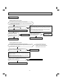
10-5. TROUBLESHOOTING FLOW
A How to check inverter/compressor
Disconnect the terminal of the compressor. 3 minutes after turning on the power supply, start EMERGENCY OPERATION.
Measure the voltage between each lead wire leading
to the compressor.
U (BLK) - V (WHT)
V (WHT) - W (RED)
W (RED) - U (BLK)
Is there output voltage?
Yes
Is output balanced?
Yes
•After the outdoor fan starts running, wait for 1 minute or more before measuring the voltage.
•Output voltage is 50 - 130 V. (The voltage may differ according to the tester.)
No
No
Is the input voltage to the outdoor electronic control
P.C. board 370 V or more?
Yes
No
Turn off power supply of indoor and outdoor unit, and
measure the compressor winding resistance between
the compressor terminals.
Is the resistance between each terminal normal?
No
Yes
Replace the power board.
Replace the compressor.
Reconnect the lead wire of compressor, and turn on power
supply to indoor and outdoor unit.
3 minutes later, starts EMERGENCY OPERATION.
Clarify the causes by counting time until the inverter stops.
0 to 10 seconds: compressor rare short
10 to 60 seconds: compressor lock
60 seconds to 5 minutes: refrigerant circuit defective
5 minutes or more: normal
30
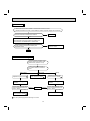
B Check of outdoor thermistors
Disconnect the connector of thermistor in the outdoor P.C. board (see
below table), and measure the resistance of thermistor.
Is the thermistor normal? (Refer to 10-6.1.)
Yes
No
Replace the thermistor except RT64.
When RT64 is abnormal, replace the
outdoor power board.
Reconnect the connector of thermistor.
Turn ON the power supply and press EMERGENCY OPERATION switch.
Does the unit operate for 10 minutes or more
without showing thermistor abnormality?
Yes
No
Replace the outdoor power board.
OK.
(Cause is poor contact.)
Thermistor
Defrost (MUZ)
Discharge temperature
Outdoor heat exchanger temperature
Ambient temperature
Fin temperature
Symbol
RT61
RT62
RT68
RT65
RT64
Connector, Pin No.
Between CN661 pin1 and pin2
Between CN661 pin3 and pin4
Between CN661 pin7 and pin8
Between CN663 pin1 and pin2
Between CN3 pin1 and pin2
31
Board
Outdoor electronic control P.C. board
Outdoor power board
C Check of R.V. coil
MUZ-D30/36
• Heating operation does not work.
1. Disconnect the lead wire leading to the compressor.
2. 3 minutes after turning on the power supply, start EMERGENCY
OPERATION in HEAT mode.
Is there voltage of 208/230 VAC between pin1
and pin 2 at connector CN912?
Yes
No
Turn OFF power supply of indoor and outdoor unit.
Disconnect the connector CN912 in noise filter
P.C. board. Is there normal
resistance to R.V. coil?
No
Replace the R.V. coil.
1. Turn off power supply of indoor and outdoor unit, and disconnect the connector CN781 in the outdoor electronic control P.C.
board.
2. 3 minutes after turning ON the power supply, start EMERGENCY OPERATION in HEAT mode.
Is there voltage 12 VDC between the connector CN781
pin 5 (+) and pin 3 (-)?
No
Replace the electronic
control P.C. board.
Yes
Yes
Replace the noise filter P.C. board.
Replace the 4-way valve.
• Cooling operation does not work.
1. Disconnect the lead wire leading to the compressor.
2. 3 minutes after turning on the power supply, start EMERGENCY
OPERATION in COOL mode.
Is there voltage of 208/230 VAC between pin1
and pin 2 at connector CN912?
No
If the connector CN912 is not
connected or R.V. coil is open,
voltage occurs between terminals
even when the control is OFF.
Replace the 4-way valve.
1. Turn OFF power supply of indoor and outdoor unit, and
disconnect the connector CN781 in the outdoor electronic
control P.C. board.
2. 3 minutes after turning ON the power supply, start EMERGENCY OPERATION in COOL mode.
Is there voltage 12 VDC between the connector
CN781 pin 5 (+) and pin 3 (-)?
No
Replace the noise filter P.C. board.
Yes
Replace the outdoor electronic control P.C. board.
32
D Check of outdoor fan motor
Check the connection between the
connector CN931 and CN932.
Is the resistance between each terminal of outdoor fan motor normal?
(Refer to 10-4.)
No
Yes
Disconnect CN932 from outdoor electronic control P.C. board,
and turn on the power supply.
Rotate the outdoor fan motor manually and measure the voltage
of CN931.
Between 1(+) and 5(-)
Between 2(+) and 5(-)
Between 3(+) and 5(-)
(Fixed to either 5 or 0 VDC)
No
No
Replace the outdoor DC fan motor.
Does the voltage between each terminal become 5 VDC
and 0 VDC repeatedly?
Yes
Does the outdoor fan motor rotate smoothly?
Yes
Replace the outdoor electronic control P.C. board.
E Check of power supply
Check the connecting of parts of main power
supply circuit.
Turn ON power supply.
Is there voltage of 208/230 VAC in the power
supply terminal block?
Yes
No
Is the output voltage from the noise filter P.C.
board 208/230 VAC?
Yes
No
Is the input voltage to the power board
208/230 VAC?
Yes
No
Replace the reactor.
Is the input voltage to the outdoor electronic
control P.C. board 294/325 VDC?
Yes
No
Replace the power board.
Check the power supply cable.
Replace the noise filter P.C. board.
Replace the outdoor electronic control P.C. board.
33
F Check of compressor start failure
Confirm that 1~4 is normal.
•Electrical circuit check
1. Contact of lead wire leading to compressor
2. Output voltage of the outdoor electronic control P.C. board and balance of them
(See 10-5. )
3. Direct current voltage to the outdoor electronic control P.C. board
4. Voltage between outdoor terminal block S1-S2
Does the compressor run for 10 seconds or
more after it starts?
Yes
Check the refrigerant circuit.
Check the stop valve.
No
After the compressor is heated with a drier,
does the compressor start? 1
No
Replace the compressor.
Yes
1
Heat the compressor with
a drier for about 20 minutes.
Do not recover refrigerant
gas while heating.
Compressor start failure. Activate pre-heat control.
(Refer to 9-1. "PRE-HEAT CONTROL")
Heating part
G Check of LEV
Turn ON power supply to the outdoor unit after checking
LEV coil is mounted to the LEV body securely.
Is "click - click" sound heard?
Or, do you feel vibration of the LEV coil with a hand?
Yes
Normal
No
Disconnect the connector CN795.
Is there normal resistance to LEV coil?
Yes
No
Replace the LEV coil.
34
Replace the outdoor electronic
control P.C. board.
H How to check miswiring and serial signal error
Turn OFF the power supply.
Is there rated voltage in the
power supply?
Check the power supply.
No
Yes
Turn ON the power supply.
Is there rated voltage between
outdoor terminal block S1 and
S2?
Yes
Check the wiring.
No
Press EMERGENCY OPERATION switch once.
Does the left lamp of OPERATION INDICATOR lamp light up? <Confirmation of the
power to the indoor unit>
Yes
No
Is serial signal error indicated 6 minutes later?
No
Yes
Is there any miswiring, poor
contact, or wire disconnection of the indoor/outdoor
Yes
connecting wire?
Is fuse (F65 or F66) broken?
No
Correct them.
A
Turn OFF the power supply.
Check once more if the indoor/outdoor
B connecting wire is not miswiring.
Short-circuit outdoor terminal block S2
and S3. 1
1. Miswiring may damage indoor electronic control P.C.
board during the operation.
Be sure to confirm the wiring is correct before the operation starts.
3. Be sure to check this within 3 minutes after turning ON.
After 3 minutes, LED blinks 6 times. Even when the
inverter P.C. board or the outdoor electronic control P.C.
board is normal, LED blinks 6 times after 3 minutes.
Outdoor electronic control P.C. board
(Parts side)
Turn ON the power supply.
LED2 LED1
Lighted Blinking
A
• Turn OFF inverter-controlled lighting
equipment.
• Turn OFF the power supply and then
turn ON again.
• Press EMERGENCY OPERATION
switch.
Is serial signal
error indicated 6
minutes later?
Yes
B
• Reinstall
either the unit
or the light
away from
each other.
• Attach a filter
No on remote
control
receiving
section of the
indoor unit.
Does the LED on the inverter P.C. board or
the outdoor electronic control P.C. board
repeat "3.6-second-OFF and 0.8-secondON quick blinking"? 3
Yes
Turn OFF the power supply.
Remove the short-circuit between
outdoor terminal block S2 and S3.
Turn ON the power supply.
Is there amplitude of 10 to 20 VDC
between outdoor terminal block S2 and
S3? <Confirmation of serial signal>
Yes
Is there rated voltage between
indoor terminal block S1 and S2?
<Confirmation of power voltage>
Yes
No
(Lighted
or not
lighted)
2. Be careful of the residual voltage
of smoothing capacitor.
No
Is there any error of the indoor/outdoor connecting wire,
such as the damage of the wire,
Yes
intermediate connection, poor
contact to the terminal block?
No
No
Is there any error of the indoor/outdoor connecting wire,
such as the damage of the wire,
Yes
intermediate connection, poor
contact to the terminal block?
No
Replace the indoor electronic control P.C. board.
Be sure to release the failure-mode recall function
after checking.
35
Replace the inverter P.C. board or
the outdoor electronic control P.C. board.
2
Replace the indoor/
outdoor connecting
wire.
Replace the indoor/
outdoor connecting
wire.
I Check of HPS
1. Disconnect the connector CN681 in the electronic control P.C. board.
2. Check the resistance of HPS 1 minute after the outdoor unit power supply was turned OFF.
Check the resistance between each terminal.
Infinity
Replace HPS.
0Ω
Reconnect CN681.
Turn ON power supply to the indoor and outdoor unit.
3 minutes later, start EMERGENCY OPERATION.
Is HPS protection displayed immediately after
compressor starts?
No
Yes
Replace the outdoor electronic
control P.C. board.
Normal
J Check of bus-bar voltage
•Check the voltage of power supply.
•Confirm outdoor unit failure mode
recall function. (Refer to 10-2.2)
Confirm LED1 indication lamp on
the outdoor electronic control P.C.
board.
Blink 5 times
Replace the power board.
Blink 6 times
Replace the outdoor electronic control P.C. board.
Turn ON power supply. Start
operation.
Confirm LED1 indication lamp
on the outdoor electronic control P.C. board.
Blink 9 times
Lighting
Replace the outdoor electronic control P.C. board.
Turn ON power supply. Start
operation.
Lighting
Normal.
Lighting
Replace the outdoor electronic control P.C. board.
Confirm LED1 indication lamp
on the outdoor electronic control P.C. board.
Blink 9 times
Replace the power board.
Turn OFF power supply before removing P.C. board.
36
K Electromagnetic noise enters into TV sets or radios
Is the unit grounded?
Ground the unit.
No
Yes
Is the distance between the antennas
and the indoor unit within 9.91 ft., or is
the distance between the antennas and
the outdoor unit within 9.91 ft.?
Yes
Extend the distance between the antennas and
the indoor unit, and/or the antennas and the
outdoor unit.
Yes
Extend the distance between the TV sets and/or
radios and the indoor unit, or the TV sets or
radios and the outdoor unit.
Yes
Replace or repair the antenna.
Replace or repair the coaxial cable.
Yes
Extend the distance between the indoor/outdoor
connecting wire of the air conditioner and the wiring of the antennas.
No
Is the distance between the TV sets or
radios and the indoor unit within 3.28
ft., or is the distance between the TV
sets or radios and the outdoor unit
within 9.91 ft.?
No
Are the antennas damaged?
Is the coaxial cable damaged?
Is there any poor contact in the antenna wiring?
No
Is the indoor/outdoor connecting wire of
the air conditioner and the wiring of the
antennas close?
No
Even if all of the above conditions are fulfilled, the electromagnetic noise may enter, depending on the electric field strength
or the installation condition (combination of specific conditions such as antennas or wiring).
Check the followings before asking for service.
1. Devices affected by the electromagnetic noise
TV sets, radios (FM/AM broadcast, shortwave)
2. Channel, frequency, broadcast station affected by the electromagnetic noise
3. Channel, frequency, broadcast station unaffected by the electromagnetic noise
4. Layout of:
indoor/outdoor unit of the air conditioner, indoor/outdoor wiring, grounding wire, antennas, wiring from antennas, receiver
5. Electric field intensity of the broadcast station affected by the electromagnetic noise
6. Presence or absence of amplifier such as booster
7. Operation condition of air conditioner when the electromagnetic noise enters in
1) Turn OFF the power supply once, and then turn ON the power supply. In this situation, check for the electromagnetic
noise.
2) Within 3 minutes after turning ON the power supply, press OPERATE/STOP (ON/OFF) button on the remote controller for
power ON, and check for the electromagnetic noise.
3) After a short time (3 minutes later after turning ON), the outdoor unit starts running. During operation, check for the electromagnetic noise.
4) Press OPERATE/STOP (ON/OFF) button on the remote controller for power OFF, when the outdoor unit stops but the
indoor/outdoor communication still runs on. In this situation, check for the electromagnetic noise.
37
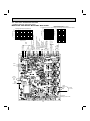
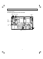
10-6. TEST POINT DIAGRAM AND VOLTAGE
1. Outdoor electronic control P.C. board
MUZ-D30NA MUZ-D36NA MUY-D30NA MUY-D36NA
Defrost thermistor (RT61)
Ambient temperature thermistor (RT65)
Fin temperature thermistor (RT64) Outdoor heat exchanger temperature thermistor (RT68)
200
68
86
104 122 140 176 194 122 212 230 248
Resistance (kΩ)
50
40
40
30
20
0
32 50 68 86 104 122 140 158 176
Temperature (°F)
20
10
0
-4
14
32
50
68
86
Temperature (°F)
104
(
CN931
5 VDC
pulse wave
5V
GND
CN932
20-90 VAC
60
60
(
To fan
motor
Temperature (°F)
80
70
CN795
12 VDC
pulse wave
50
100
80
LEV
100
120
GND (power board) CN781
Rush current relay (–)
12
R.V. coil (–)
VDC
(+)
200
140
(+)
Resistance (kΩ)
300
Outdoor heat exchanger temperature
thermistor (RT68) CN661
400
90
160
Ambient temperature
CN663
thermistor (RT65)
CN701
(–) Signal transmission
(+) (To power board)
5 VDC pulse wave
CN702
(+)
Signal reception
GND (From power board)
5 VDC pulse wave
(–)
15 V
15 V
500
Defrost thermistor (RT61)
(MUZ) CN661
Discharge temperature thermistor (RT62)
CN661
Resistance (kΩ)
600
0
32
100
180
(–)
Discharge temperature thermistor (RT62)
700
LED 1
LED 2
CN801
294 ~ 370
VDC
Input
F801
FUSE
T3.15AL250V
CN601
208/230 VAC
60 Hz
Input
for indoor
5~10 VDC
CN681
High pressure switch
38
2. Noise filter P.C. board
MUZ-D30NA MUZ-D36NA MUY-D30NA MUY-D36NA
CN901
CN903
To electronic CN902
control P.C. To power To power
board
board
board
208/230 VAC
60 Hz
Input
MUZ
CN912
R.V. coil
208/230 VAC
60 Hz
Output
208/230 VAC
60 Hz
Output
CN61
F64 FUSE
T2AL250V
39
NR64 VARISTOR
3. Outdoor power board
MUZ-D30NA MUZ-D36NA MUY-D30NA MUY-D36NA
Connect to the compressor
Voltage among phases: 180 V
Connect to the ground
294-370 VDC
Output (Red)
(+) 1
CN2
Connect to the controller board
(+)1-5(–): Signal transmission
(To electronic control P.C. board)
5 VDC pulse wave
(+)2-5(–): Zero cross signal
3-4 : Not used
(+)6-5(–): 15 V
(+)7-5(–): 15 V
(–) 3
(White)
CN3
Fin temperature thermistor RT64
Signal reception (From electronic
control P.C. board)
5 VDC pulse wave
CN5
Primary current detection
(Connect to the noise filter)
40
11
DISASSEMBLY INSTRUCTIONS
<"Terminal with locking mechanism" Detaching points>
The terminal which has the locking mechanism can be detached as shown below.
There are two types (refer to (1) and (2)) of the terminal with locking mechanism.
The terminal without locking mechanism can be detached by pulling it out.
Check the shape of the terminal before detaching.
(1) Slide the sleeve and check if there is a locking lever or not.
Sleeve
Locking lever
(2) The terminal with this connector has the
locking mechanism.
Slide the sleeve.
Pull the terminal while
pushing the locking
lever.
Hold the sleeve, and
pull out the terminal
slowly.
Connector
MUZ-D30NA MUZ-D36NA MUY-D30NA MUY-D36NA
NOTE: Turn OFF power supply before disassembly.
OPERATING PROCEDURE
PHOTOS
1. Removing the cabinet
Photo 1
(1) Remove the screws of the service panel.
(2) Remove the screws of the top panel.
(3) Remove the screw of the valve cover.
(4) Remove the service panel.
(5) Remove the top panel.
(6) Remove the valve cover.
(7) Remove the screws of the cabinet.
(8) Remove the cabinet.
(9) Remove the screws of the back panel.
(10) Remove the back panel.
Screw of
the top
panel
Screws
of the
cabinet
Screws of the cabinet
Photo 2
Photo 3
Screw of the motor support
Screw of the service panel
Screws of the
top panel
Conduit plate
Set screws of
the back panel
Screws of
the back
panel
Screws
of the
cabinet
Screw of the
valve cover
Set screws of the back panel
41
OPERATING PROCEDURE
PHOTOS
2. Removing the inverter assembly, P.C. board and
power board
Photo 4
(1) Remove the top panel, cabinet, service panel and the back
panel. (Refer to 1.)
(2) Disconnect the following connectors:
<Electronic control P.C. board>
CN931 and CN932 (Fan motor)
CN795 (LEV)
CN661 (Discharge temperature thermistor, defrost thermistor (MUZ) and outdoor heat exchanger temperature thermistor)
CN663 (Ambient temperature thermistor)
CN681 (High pressure switch) (MUZ)
<Noise filter P.C. board>
CN912 (4-way valve) (MUZ)
<Compressor>
<Reactor>
(4) Remove the screws fixing the relay panel.
(5) Remove the inverter assembly.
(6) Disconnect all connectors and lead wires on the electronic
control P.C. board.
(7) Remove the electronic control P.C. board from the inverter
assembly.
(8) Remove the screws fixing the power board assembly.
(9) Disconnect all connectors and lead wires on the power
board.
(10) Remove the power board from the inverter assembly.
(11) Disconnect all connectors and lead wires on the noise filter
P.C. board.
(12) Remove the noise filter P.C. board from the inverter assembly.
Screws of the reactor
HPS
Discharge temperature
thermistor
Photo 5 (Inverter assembly)
Screws of the power board assembly
3. Removing R.V. coil (MUZ)
(1) Remove the top panel, cabinet, service panel and the back
panel. (Refer to 1.)
(2) Disconnect the following connectors:
<Noise filter P.C. board>
CN912 (4-way valve)
(3) Remove the R.V. coil. (Photo 9)
Screws of the relay panel
Photo 6
Screws of the
relay panel
Propeller
42
OPERATING PROCEDURE
PHOTOS
4. Removing the defrost thermistor (MUZ), discharge
temperature thermistor, outdoor heat exchanger
temperature thermistor and ambient temperature
thermistor
(1) Remove the top panel, cabinet, service panel and the back
panel. (Refer to 1.)
(2) Disconnect the following connectors:
<Electronic control P.C. board>
CN661 (Discharge temperature thermistor, defrost thermistor (MUZ) and outdoor heat exchanger temperature thermistor)
CN663 (Ambient temperature thermistor)
(3) Pull out the defrost thermistor from its holder. (MUZ)
(4) Pull out the discharge temperature thermistor from its holder. (Photo 4)
(5) Pull out the outdoor heat exchanger temperature thermistor
from its holder.
(6) Pull out the ambient temperature thermistor from its holder.
Photo 7
Outdoor heat
exchanger
temperature
thermistor
Ambient
temperature
thermistor
Defrost
thermistor
(for MUZ)
5. Removing outdoor fan motor
(1) Remove the top panel, cabinet, service panel and the back
panel. (Refer to 1.)
(2) Disconnect the following connectors:
<Electronic control P.C. board>
CN931 and CN932 (Fan motor)
(3) Remove the propeller.
(4) Remove the screws fixing the outdoor fan motor.
(5) Remove the outdoor fan motor.
43
Photo 8
Propeller
Screws of the outdoor fan motor
OPERATING PROCEDURE
6. Removing the compressor and 4-way valve
PHOTOS
Photo 9
(1) Remove the top panel, cabinet, service panel and the back
panel. (Refer to 1.)
(2) Remove the inverter assembly. (Refer to 2.)
(3) Remove the R.V. coil. (Refer to 3.)
(4) Recover gas from the refrigerant circuit.
NOTE: Recover gas from the pipes until the pressure gauge
shows 0 PSIG.
(5) Detach the brazed part of the suction and the discharge
pipe connected with compressor.
(6) Remove the compressor nuts.
(7) Remove the compressor.
(8) Detach the brazed part of 4-way valve and pipe. (Photo 8)
Brazed parts of 4-way valve
R.V. coil
Photo 10
Brazed part of the
discharge pipe
Brazed part of the
suction pipe
7. Removing the reactor
(1) Remove the top panel, cabinet, service panel and the back
panel. (Refer to 1.)
(2) Disconnect the reactor lead wire.
(3) Remove the screws of the reactor, and remove the reactor.
HEAD OFFICE: TOKYO BLDG., 2-7-3, MARUNOUCHI, CHIYODA-KU, TOKYO 100-8310, JAPAN
© Copyright 2008 MITSUBISHI ELECTRIC CO.,LTD
Distributed in Jul. 2011. No. OBH502 REVISED EDITION-C
Distributed in Jan. 2009. No. OBH502 REVISED EDITION-B 5
Distributed in Mar. 2008. No. OBH502 REVISED EDITION-A 7
Distributed in Feb. 2008. No. OBH502 7
Made in Japan
New publication, effective Jul. 2011
Specifications subject to change without notice.