1
Sun StorEdge™ 3000 Family
Installation, Operation, and Service
Manual
Sun StorEdge 3120 SCSI Array
Sun Microsystems, Inc.
www.sun.com
Part No. 816-7956-11
July 2004, Revision A
Submit comments about this document at: http://www.sun.com/hwdocs/feedback
Copyright © 2004 Dot Hill Systems Corporation, 6305 El Camino Real, Carlsbad, California 92009, USA. All rights reserved.
Sun Microsystems, Inc. and Dot Hill Systems Corporation may have intellectual property rights relating to technology embodied in this product
or document. In particular, and without limitation, these intellectual property rights may include one or more of the U.S. patents listed at
http://www.sun.com/patents and one or more additional patents or pending patent applications in the U.S. and other countries.
This product or document is distributed under licenses restricting its use, copying distribution, and decompilation. No part of this product or
document may be reproduced in any form by any means without prior written authorization of Sun and its licensors, if any.
Third-party software is copyrighted and licensed from Sun suppliers.
Parts of the product may be derived from Berkeley BSD systems, licensed from the University of California. UNIX is a registered trademark in
the U.S. and in other countries, exclusively licensed through X/Open Company, Ltd.
Sun, Sun Microsystems, the Sun logo, Sun StorEdge, AnswerBook2, docs.sun.com, and Solaris are trademarks or registered trademarks of Sun
Microsystems, Inc. in the U.S. and in other countries.
U.S. Government Rights—Commercial use. Government users are subject to the Sun Microsystems, Inc. standard license agreement and
applicable provisions of the FAR and its supplements.
DOCUMENTATION IS PROVIDED “AS IS” AND ALL EXPRESS OR IMPLIED CONDITIONS, REPRESENTATIONS AND WARRANTIES,
INCLUDING ANY IMPLIED WARRANTY OF MERCHANTABILITY, FITNESS FOR A PARTICULAR PURPOSE OR NONINFRINGEMENT,
ARE DISCLAIMED, EXCEPT TO THE EXTENT THAT SUCH DISCLAIMERS ARE HELD TO BE LEGALLY INVALID.
Copyright © 2004 Dot Hill Systems Corporation, 6305 El Camino Real, Carlsbad, Californie 92009, Etats-Unis. Tous droits réservés.
Sun Microsystems, Inc. et Dot Hill Systems Corporation peuvent avoir les droits de propriété intellectuels relatants à la technologie incorporée
dans le produit qui est décrit dans ce document. En particulier, et sans la limitation, ces droits de propriété intellectuels peuvent inclure un ou
plus des brevets américains énumérés à http://www.sun.com/patents et un ou les brevets plus supplémentaires ou les applications de brevet
en attente dans les Etats-Unis et dans les autres pays.
Ce produit ou document est protégé par un copyright et distribué avec des licences qui en restreignent l’utilisation, la copie, la distribution, et la
décompilation. Aucune partie de ce produit ou document ne peut être reproduite sous aucune forme, par quelque moyen que ce soit, sans
l'autorisation préalable et écrite de Sun et de ses bailleurs de licence, s’il y ena.
Le logiciel détenu par des tiers, et qui comprend la technologie relative aux polices de caractères, est protégé par un copyright et licencié par des
fournisseurs de Sun.
Des parties de ce produit pourront être dérivées des systèmes Berkeley BSD licenciés par l’Université de Californie. UNIX est une marque
déposée aux Etats-Unis et dans d’autres pays et licenciée exclusivement par X/Open Company, Ltd.
Sun, Sun Microsystems, le logo Sun, Sun StorEdge, AnswerBook2, docs.sun.com, et Solaris sont des marques de fabrique ou des marques
déposées de Sun Microsystems, Inc. aux Etats-Unis et dans d’autres pays.
LA DOCUMENTATION EST FOURNIE “EN L’ÉTAT” ET TOUTES AUTRES CONDITIONS, CONDITIONS, DECLARATIONS ET
GARANTIES EXPRESSES OU TACITES SONT FORMELLEMENT EXCLUES, DANS LA MESURE AUTORISEE PAR LA LOI APPLICABLE,
Y COMPRIS NOTAMMENT TOUTE GARANTIE IMPLICITE RELATIVE A LA QUALITE MARCHANDE, A L'APTITUDE A UNE
UTILISATION PARTICULIERE OU A L’ABSENCE DE CONTREFAÇON.
Please
Recycle
Contents
Preface
1.
ix
Array Overview
1–1
1.1
Introducing the Array Model
1.2
Best Practices for the Sun StorEdge 3120 SCSI Array
1.2.1
Entry-level Server Storage Requirements
1.2.2
Print Server Architecture and Configuration
1.2.2.1
1.3
2.
1–1
Tips and Techniques
1–2
1–3
1–3
1–5
1.2.3
File Server Architecture and Configuration
1.2.4
Application Server Architecture and Configuration
Additional Software Tools
Site Planning
1–5
1–6
1–8
2–1
2.1
Customer Obligations
2–2
2.2
Safety Precautions
2.3
Environmental Requirements
2.4
Electromagnetic Compatibility (EMC)
2.5
Electrical and Power Specifications
2.6
Physical Specifications
2.7
Layout Map
2–2
2–3
2–4
2–4
2–5
2–5
iii
3.
4.
5.
iv
2.8
Rack Placement
2–6
2.9
Preinstallation Worksheet
Inspecting the Array Package
2–6
3–1
3.1
Unpacking the Array
3–1
3.2
Checking the Package Contents
3.3
Field-Replaceable Units
3.4
Customer-Provided Cables
Connecting Your SCSI Array
3–2
3–3
3–3
4–1
4.1
Converting Your Front Bezel Locks So the Keys Cannot Be Removed
4.2
Rackmounting the Array
4.3
Connecting Chassis to an AC Power Outlet
4.4
Connecting the Chassis to DC Power Outlets
4.5
Bus and Cable Lengths
4.6
Connecting Sun StorEdge 3120 SCSI Arrays to Hosts
4–2
4–4
4–4
4–6
4–7
4–8
4.6.1
Single-Bus (SB) Label
4.6.2
Fixed Drive IDs
4.6.3
Connecting Cables for a Single-Bus Configuration
4.6.4
A Single-Bus JBOD with One Host Connection
4.6.5
A Single-Bus, Multi-Initiator JBOD Configuration
4.6.6
A Split-Bus, Single-Initiator JBOD Configuration
4.6.7
A Split-Bus, Multi-Initiator JBOD Configuration Connected to One
JBOD 4–18
Software Management Tools
4–9
4–10
4–11
4–12
4–14
4–15
5–1
5.1
Overview of Provided Software
5–1
5.2
Monitoring with the Sun StorEdge Configuration Service
5.2.1
Enabling JBOD Support
5.2.2
Viewing Component and Alarm Characteristics
5–2
5–2
Sun StorEdge 3000 Family Installation, Operation, and Service Manual • July 2004
5–4
5.3
Event Messages from the Sun StorEdge Diagnostic Reporter
5.4
Monitoring with the Sun StorEdge CLI
exit
5–7
help
5–8
quit
5–8
5–8
select
set led
5–9
5–10
show configuration
5–12
show enclosure-status
show frus
5–13
show inquiry-data
5–15
5–15
show led-status
5–16
show safte-devices
version
7.
5–7
5–7
about
6.
5–17
5.5
Managing Disks in the Sun StorEdge 3120 SCSI Array
5.6
Enabling VERITAS DMP in a Single-Bus Configuration
Checking LEDs
5–17
5–17
6–1
6.1
LEDs When Array Is First Powered On
6.2
Front-Panel LEDs
6–2
6.3
Back-Panel LEDs
6–4
6–1
Maintaining and Troubleshooting Your Array
7.1
Upgrading Firmware
7.2
Failed Component Alarms
7.3
Silencing Audible Alarms
7.4
General Troubleshooting Guidelines
7.4.1
5–6
7–1
7–2
7–2
7–3
7–4
Writing Events to a Log File for an IBM AIX Host
7–5
Contents
v
7.5
Troubleshooting Solaris Operating System Configuration Issues
7.6
JBOD Disks Not Visible to the Host
7.7
8.
Making JBODs Visible to Hosts Running the Solaris Operating
System 7–7
7.6.2
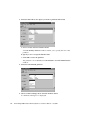
Making JBODs Visible to Hosts Running the Windows NT
Operating System 7–7
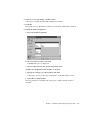
7.6.3
Making JBODs Visible to Hosts Running the Windows 2000 and
Windows 2003 Operating Systems 7–10
7.6.4
Making JBODs Visible to Hosts Running the Linux Operating
System 7–14
7.6.5
Making JBODs Visible to Hosts Running the
HP-UX Operating System 7–15
7.6.6
Making JBODs Visible to Hosts Running the
IBM AIX Operating System 7–15
Identifying a Failed Drive for Replacement
Installing FRUs
8–1
Available FRUs
8.2
Static Electricity and Other Precautions
8.3
Disk Drive and Air Management Sled FRUs
8.4
8–1
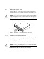
Replacing a Disk Drive
8–2
8–3
8–4
8.3.1.1
Identifying the Defective Disk Drive
8.3.1.2
Removing a Defective Disk Drive
8.3.1.3
Installing a New Disk Drive
Installing an Air Management Sled
Power and Fan Module FRUs
8.4.1
7–17
7–19
8.1
8.3.2
7–17
Verifying Operating System Device Information
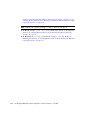
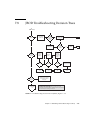
JBOD Troubleshooting Decision Trees
8.3.1
vi
7–6
7.6.1
7.7.1
7.8
7–6
8–4
8–5
8–6
8–7
8–7
Replacing an AC Power Supply/Fan Module
8–8
8.4.1.1
Removing an AC Power Supply/Fan Module
8.4.1.2
Installing an AC Power Supply/Fan Module
Sun StorEdge 3000 Family Installation, Operation, and Service Manual • July 2004
8–8
8–8
8.4.2
8.5
Replacing a DC Power Supply/Fan Module
8–9
8.4.2.1
Removing a DC Power Supply/Fan Module
8–9
8.4.2.2
Installing an DC Power Supply/Fan Module
8–10
Installing a JBOD Chassis FRU
A. SCSI Array Specifications
8–11
A–1
A.1
Summary of Physical Specifications
A.2
Summary of Sun StorEdge 3120 SCSI Array Specifications
A.3
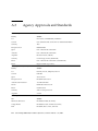
Agency Approvals and Standards
A.4
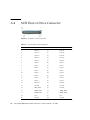
SCSI Host or Drive Connector
A.5
SCSI Host or Drive Cable
Index
A–2
A–3
A–4
A–6
A–7
Index–1
Contents
vii
viii
Sun StorEdge 3000 Family Installation, Operation, and Service Manual • July 2004
Preface
This manual provides instructions for installing, initially configuring, and operating
your Sun StorEdge™ 3120 SCSI array.
Caution – You should read the Sun StorEdge 3000 Family Safety, Regulatory, and
Compliance Manual before beginning any procedure in this manual.
How This Book Is Organized
This book contains the following topics:
Chapter 1 provides an overview of the array’s features.
Chapter 2 covers the site planning and basic safety requirements.
Chapter 3 provides general procedures for unpacking and inspecting the array.
Chapter 4 provides procedures for connecting your array to power and to the
network.
Chapter 5 provides procedures for configuring your array with software
management tools.
Chapter 6 describes the array’s front and back panel LEDs.
Chapter 7 describes maintenance and troubleshooting procedures.
Chapter 8 provides instructions for removing and installing field-replaceable units
(FRUs) in Sun StorEdge 3120 SCSI arrays.
Appendix A provides Sun StorEdge 3120 SCSI array specifications.
ix
Using UNIX Commands
This document might not contain information on basic UNIX® commands and
procedures such as shutting down the system, booting the system, and configuring
devices. See the following for this information:
See one or more of the following for this information:
■
■
■
■
Solaris Handbook for Sun Peripherals
AnswerBook2™ online documentation for the Solaris™ operating environment
Software documentation that you received with your system
Solaris™ operating environment documentation, which is at:
http://docs.sun.com
Shell Prompts
x
Shell
Prompt
C shell
machine-name%
C shell superuser
machine-name#
Bourne shell and Korn shell
$
Bourne shell and Korn shell superuser
#
Sun StorEdge 3000 Family Installation, Operation, and Service Manual • July 2004
Typographic Conventions
Typeface*
Meaning
Examples
AaBbCc123
The names of commands, files,
and directories; on-screen
computer output
Edit your .login file.
Use ls -a to list all files.
% You have mail.
AaBbCc123
What you type, when contrasted
with on-screen computer output
% su
Password:
AaBbCc123
Book titles, new words or terms,
words to be emphasized.
Replace command-line variables
with real names or values.
Read Chapter 6 in the User’s Guide.
These are called class options.
You must be superuser to do this.
To delete a file, type rm filename.
* The settings on your browser might differ from these settings.
Related Documentation
Title
Part Number
Sun StorEdge 3120 SCSI Array Release Notes
816-7955
Sun StorEdge 3000 Family Software Installation Guide
817-3764
Sun StorEdge 3000 Family Configuration Service 1.5 User’s Guide
817-3337
Sun StorEdge 3000 Family Diagnostic Reporter 1.5 User’s Guide
817-3338
Sun StorEdge 3000 Family CLI 1.6 User’s Guide
817-4951
Sun StorEdge 3000 Family Rack Installation Guide for 1U Arrays
816-7964
Sun StorEdge 3000 Family Safety, Regulatory, and Compliance Manual
816-7930
Preface
xi
Accessing Sun Documentation
All Sun StorEdge 3120 SCSI array documentation is available online in both PDF and
HTML format at the following location:
http://www.sun.com/products-n-solutions/hardware/docs/
Network_Storage_Solutions/Workgroup/3120
or
http://docs.sun.com/db/coll/3120SCSIarray
You can view, print, or purchase a broad selection of Sun documentation at:
http://www.sun.com/documentation
Contacting Sun Technical Support
For late-breaking news and troubleshooting tips, review the Sun StorEdge 3120 SCSI
Array Release Notes located at:
http://www.sun.com/products-n-solutions/hardware/docs/
Network_Storage_Solutions/Workgroup/3120
If you have technical questions about this product that are not answered in the
documentation, go to:
http://www.sun.com/service/contacting
To initiate or check on a USA-only service request, contact Sun support at:
800-USA-4SUN
To obtain international technical support, contact the sales office of each country at:
http://www.sun.com/service/contacting/sales.html
xii
Sun StorEdge 3000 Family Installation, Operation, and Service Manual • July 2004
508 Accessibility Features
The Sun StorEdge documentation is available in 508-compliant HTML files that can
be used with assistive technology programs for visually impaired personnel. These
files are provided on the Documentation CD for your product as well as on the
websites identified in the previous “Accessing Sun Documentation” section.
Additionally, the software and firmware applications provide keyboard navigation
and shortcuts, which are documented in the user's guides.
Sun Welcomes Your Comments
Sun is interested in improving its documentation and welcomes your comments and
suggestions. You can submit your comments by going to:
http://www.sun.com/hwdocs/feedback
Please include the title and part number of your document with your feedback:
Sun StorEdge 3000 Family Installation, Operation, and Service Manual, part number 8167956-11
Preface
xiii
xiv
Sun StorEdge 3000 Family Installation, Operation, and Service Manual • July 2004
CHAPTER
1
Array Overview
This chapter provides an overview of your Sun StorEdge 3120 SCSI array, which is
an LVD/SE device. Topics covered in this chapter are:
■
■
■
1.1
“Introducing the Array Model” on page 1-1
“Best Practices for the Sun StorEdge 3120 SCSI Array” on page 1-2
“Additional Software Tools” on page 1-8
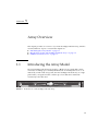
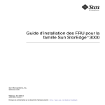
Introducing the Array Model
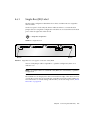
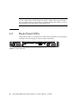
The Sun StorEdge 3120 SCSI array model is a JBOD (an array with disks and no
controller). Providing up to 584-Gbyte RAID based on 146-Gbyte drives in a 1.75inch tall by 19-inch wide storage unit, the Sun StorEdge 3120 SCSI array is a highperformance, storage device that contains up to four disk drives with SCSI
connectivity to the data host.
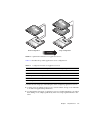
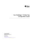
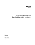
FIGURE 1-1
Front View of a Sun StorEdge 3120 SCSI Array
1-1
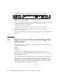
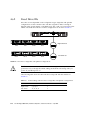
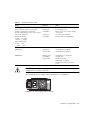
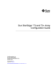
The JBOD (Just a Bunch of Disks) array connects directly to a host server.
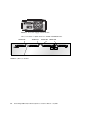
FIGURE 1-2
Rear View of a JBOD
Extensive reliability, availability, and serviceability (RAS) features include redundant
components, notification of failed components, and the ability to replace
components while the array is online.
The JBOD can be rackmounted in a server cabinet or expansion cabinet.
For information about specifications and agency approvals, see “SCSI Array
Specifications” on page A-1.
This document highlights SCSI best practices, which apply to the Sun StorEdge 3120
SCSI array.
1.2
Best Practices for the Sun StorEdge 3120
SCSI Array
The following sections outline small and large storage solutions for common entrylevel server environments:
■
■
■
Print
File
Application
These solutions can optimally use the Sun StorEdge 3120 SCSI array, a nextgeneration Ultra3 SCSI storage system designed to provide direct attached storage
(DAS) to entry-level servers.
These solutions feature many performance features using familiar SCSI technology.
Entry-level servers are used for wide range of applications with distinct storage
requirements, so the Sun StorEdge 3120 SCSI array features a modular architecture
with flexible configurations. Modularity and flexibility enable the storage solution to
quickly and easily adapt to a particular environment.
1-2
Sun StorEdge 3000 Family Installation, Operation, and Service Manual • July 2004
1.2.1
Entry-level Server Storage Requirements
Print, file, and application services are essential network requirements and are
among the most popular uses of entry-level servers. The servers used to provide
these functions are generally very inexpensive, highly compact units that are often
installed in racks for convenience.
One example of such a server is the Sun Fire V120, an expandable single-processor
server that occupies just 1 unit (1U) of rack space. Network servers are often
distributed throughout an enterprise, making the Sun StorEdge 3120 SCSI array
ideally suited for these applications due to its cost-effective direct attached storage
design.
TABLE 1-1
1.2.2
Storage Requirements for Single Processor Servers
Print Server
File Server
Application Server
Availability
Medium
Medium to high
Medium to high
Storage capacity
Low
Low to high
Low to medium
Special needs
High data rates
and low cost
High data and
transaction rates
Low cost and high
transaction rates
Access pattern
Sequential
Sequential
Random
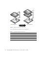
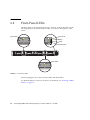
Print Server Architecture and Configuration
The following section outlines small and large storage solutions for print server
environments. FIGURE 1-3 shows the scalability between the print server and the Sun
StorEdge 3120 SCSI array.
Chapter 1
Array Overview
1-3
Small Configuration
Large Configuration
Scalability
FIGURE 1-3
Optimized Architecture for Print Servers
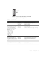
TABLE 1-2 describes the possible print server configurations.
TABLE 1-2
1-4
Configuration Details for Print Servers
Small Configuration
Large Configuration
JBOD Enclosures
1
1
Number of Disks
2
4
Bus Configuration
Split-bus
Split-bus
RAID Levels Used
Host-based RAID 1
Host-based RAID 1
Drive Configuration
1 LUN
2 LUNs
Sun StorEdge 3000 Family Installation, Operation, and Service Manual • July 2004
1.2.2.1
Tips and Techniques
Consider the following tips and techniques when configuring print servers.
1.2.3
■
Using a server’s built-in SCSI port (if compatible) to minimize cost will result in
satisfactory print server performance in most environments, even if the SCSI port
does not operate at full Ultra320 speeds.
■
Data protection should be provided by host-based software volume management
software using the operating system’s volume manager or a third-party volume
manager. The recommended configurations provide RAS similar to a single
controller RAID array.
■
Each server must be connected to a different SCSI bus when using the large
recommended configuration.
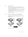
File Server Architecture and Configuration
The following section outlines small and large storage solutions for file server
environments. FIGURE 1-4 shows the scalability between the file server and the Sun
StorEdge 3120 SCSI array.
Small Configuration
FIGURE 1-4
Scalability
Large Configuration
Optimized Architecture for File Servers
Chapter 1
Array Overview
1-5
TABLE 1-3 describes the possible file server configurations.
TABLE 1-3
Configuration Details for File Servers
Small Configuration
Large Configuration
JBOD Enclosures
1
1
Number of Disks
2
4
Bus Configuration
Single-bus
Split-bus
RAID Levels Used
Host-based RAID 1
Host-based RAID 1
Drive Configuration
1 LUN
2 LUNs
Consider the following tips and techniques when configuring file servers.
1.2.4
■
You can use an Ultra3 SCSI port to connect the RAID array whenever the server is
connected to a LAN using Gigabit Ethernet. Otherwise, a slower SCSI connection
may create a performance bottleneck on the SCSI connection.
■
If the server has room for only one host adapter and you must choose between
Ultra320 SCSI or Gigabit Ethernet adapters, install the Gigabit Ethernet host
adapter and use the server’s built-in SCSI port to provide the most benefit to
users. However, this reduces the I/O to a slower SCSI speed.
■
Rapidly growing network response times as users are added is an indication the
file server is limiting performance. If this occurs, examine the utilization of server
memory, processors, and network adapters and expand those with the highest
usage.
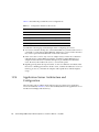
Application Server Architecture and
Configuration
The following section outlines small and large storage solutions for application
server environments. FIGURE 1-5 shows the scalability between the application server
and the Sun StorEdge 3120 SCSI array.
1-6
Sun StorEdge 3000 Family Installation, Operation, and Service Manual • July 2004
Small Configuration
Large Configuration
Scalability
FIGURE 1-5
Optimized Architecture for Application Servers
TABLE 1-4 describes the possible application server configurations.
TABLE 1-4
Configuration Details for Application Servers
Small Configuration
Large Configuration
JBOD Enclosures
1
1
Number of Disks
2
4
Bus Configuration
Split-bus
Split-bus
RAID Levels Used
Host-based RAID 1
Host-based RAID 1
Drive Configuration
1 LUN
2 LUNs
Consider the following tips and techniques when configuring application servers.
■
A single array providing storage for two servers reduces storage costs with little
to no effect on application performance.
■
Use the built-in SCSI ports of application servers to further minimize costs rather
than adding a host adapter, particularly when not using Gigabit Ethernet to the
LAN.
Chapter 1
Array Overview
1-7
■
1.3
Enhance application server availability by booting them from the RAID array
rather than their internal drives. This also facilitates the rapid replacement of
malfunctioning or failed servers.
Additional Software Tools
Additional software tools are available on the Sun Download Center located at:
http://wwws.sun.com/software/download/
The following software tools are available:
■
Sun StorEdge Configuration Service, a management and monitoring program
■
Sun StorEdge Diagnostic Reporter software, a monitoring utility
■
Sun StorEdge CLI, a command-line utility to manage the array
For details on using the software management tools with the SCSI array, see
“Software Management Tools” on page 5-1.
For other supported software tools, refer to the release notes for your array, located
at:
http://www.sun.com/products-nsolutions/hardware/docs/Network_Storage_Solutions/Workgroup/3120
1-8
Sun StorEdge 3000 Family Installation, Operation, and Service Manual • July 2004
CHAPTER
2
Site Planning
This chapter outlines the site-planning requirements and basic safety requirements
for the installation and use of Sun StorEdge 3120 SCSI arrays. Customers are asked
to complete a preinstallation worksheet and to prepare the site for installation
according to the worksheet details and the specified site planning requirements.
Review the details of this chapter before installing a Sun StorEdge 3120 SCSI array.
Topics covered in this chapter are:
■
■
■
■
■
■
■
■
■
“Customer Obligations” on page 2-2
“Safety Precautions” on page 2-2
“Environmental Requirements” on page 2-3
“Electromagnetic Compatibility (EMC)” on page 2-4
“Electrical and Power Specifications” on page 2-4
“Physical Specifications” on page 2-5
“Layout Map” on page 2-5
“Rack Placement” on page 2-6
“Preinstallation Worksheet” on page 2-6
Note – Refer to the Sun StorEdge 3120 SCSI Array Release Notes for the current lists of
supported operating environments, host platforms, software, and qualified cabinets.
2-1
2.1
Customer Obligations
The customer is obliged to inform Sun Microsystems of any and all ordinances and
regulations that would affect installation.
Caution – When selecting an installation site for the Sun StorEdge 3120 SCSI array,
choose a location that avoids excessive heat, direct sunlight, dust, or chemical
exposure. Such exposure greatly reduces the product’s longevity and might void
your warranty.
The customer is responsible for meeting all government codes and regulations
concerning facilities. The customer is also responsible for compliance with the
following requirements:
2.2
■
Meet all local, national, and international codes covered in this specification. The
subjects covered include fire and safety, building, and electrical codes.
■
Document and inform Sun Microsystems of any deviations from this
specification.
Safety Precautions
For your protection, observe the following safety precautions when setting up your
equipment:
2-2
■
Follow all safety precautions and requirements specified in the Sun StorEdge 3000
Family Safety, Regulatory, and Compliance Manual.
■
A fully loaded array weighs over 30 pounds (13.608 kg). Use two people to lift the
array to avoid injury.
■
Follow all cautions and instructions marked on the equipment.
■
Ensure that the voltage and frequency of your power source match the voltage
and frequency inscribed on the equipment’s electrical rating label.
■
Never push objects of any kind through openings in the equipment. Dangerous
voltages might be present. Conductive foreign objects could produce a short
circuit that could cause fire, electric shock, or damage to your equipment.
Sun StorEdge 3000 Family Installation, Operation, and Service Manual • July 2004
2.3
■
To reduce the risk of electric shock, do not plug Sun products into any other type
of power system. Sun products are designed to work with single-phase power
systems having a grounded neutral conductor. Contact your facilities manager or
a qualified electrician if you are not sure what type of power is supplied to your
building.
■
Your Sun product is shipped with a grounding-type (three-wire) power cord. To
reduce the risk of electric shock, always plug the cord into a grounded power
outlet.
■
Do not use household extension cords with your Sun product. Not all power
cords have the same current ratings. Household extension cords do not have
overload protection and are not meant for use with computer systems.
■
Do not block or cover the openings of your Sun product. Never place a Sun
product near a radiator or heat register. Failure to follow these guidelines can
cause overheating and affect the reliability of your Sun product.
Environmental Requirements
TABLE 2-1
Environmental Specifications
Operating
Non-Operating
Altitude
To 3000 meters (9000 feet)
To 12,000 meters (36,000 feet)
Temperature
5 degrees C to 35 degrees C
-40 degrees C to +65 degrees C
Humidity
Range
10% to 90% @ 40 degrees C
(noncondensing)
0 to 93% @ 38 degrees C
(noncondensing)
Chapter 2
Site Planning
2-3
2.4
Electromagnetic Compatibility (EMC)
The following is required for all installations:
2.5
■
All AC mains and supply conductors to power distribution boxes for the
rackmounted array must be enclosed in a metal conduit or raceway when
specified by local, national, and other applicable government codes and
regulations.
■
The supply conductors and power distribution boxes (or equivalent metal
enclosure) must be grounded at both ends.
■
The supplied arrays require voltages within minimum fluctuation.
■
The facilities voltage supplied by the customer must maintain a voltage of not
more than (+/–) 5 percent. The customer facilities must provide suitable surge
protection.
Electrical and Power Specifications
All Sun StorEdge 3120 SCSI arrays require two independent power sources. Each
array has two power-supply-and-fan modules for redundancy.
Each Sun StorEdge 3120 AC array requires two 115 VAC/15A or two 240 VAC
service outlets. All AC power supplies are autoranging and are automatically
configured to a range of 90-264 VAC and 47-63 Hz. There is no need to make special
adjustments.
Each DC array requires two –48 VDC service outlets, and has an input voltage range
of –36 VDC to –72 VDC.
Note – To ensure power redundancy, connect the two Sun StorEdge 3120 SCSI
power modules to two separate circuits (for example, one commercial circuit and
one UPS).
2-4
Sun StorEdge 3000 Family Installation, Operation, and Service Manual • July 2004
TABLE 2-2
2.6
Power Specifications
AC power:
Voltage and frequency 90 to 264 VAC, 47 to 63 Hz
Input current:
4A max
Power-supply output voltages:
+5 VDC and +12 VDC
DC power:
–48 VDC (–36 VDC to –72 VDC)
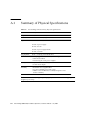
Physical Specifications
Use the following physical specifications to plan the location of your array.
TABLE 2-3
2.7
Physical Specifications
Category
Description
Dimensions
1U (1.75-inch/ 4.445 cm.) height
20-inch / 50.8 cm. chassis depth
17.5-inch / 44.45 cm. (19-inch / 48.26 cm. with ears) width
Installation clearances
For FRU removal and replacement, 15-inch (37 cm.) is required for
front and back.
Cooling clearances
6-inch (15 cm.) is required front and back. No cooling clearance is
required on the sides or the top and bottom of the array.
Layout Map
It is helpful to create a sketch or layout map to indicate the exact location for the Sun
StorEdge 3120 SCSI array installation as well as the location of the hosts.
As you lay out the components, consider the cable lengths. For more information
about cables, see “Bus and Cable Lengths” on page 4-7.
Chapter 2
Site Planning
2-5
2.8
Rack Placement
Follow these guidelines when preparing a rackmount placement for your system.
2.9
■
Ensure that the floor surface is level.
■
Leave enough space in front of the rack to access components for servicing.
■
Leave enough space in back of the rack to access components for servicing.
■
Keep power and interface cables clear of foot traffic. Route cables inside walls,
under the floor, through the ceiling, or in protective channels or raceways.
■
Route interface cables (excluding fiber-optic cables) away from motors and other
sources of magnetic or radio frequency interference.
■
Stay within the cable length limitations.
■
Provide two separate power sources for the array. These power sources must be
independent of each other, and each must be controlled by a separate circuit
breaker at the power distribution point.
Preinstallation Worksheet
When ordering a Sun StorEdge 3120 SCSI array, complete the following
Preinstallation Worksheet and then prepare the site for installation according to the
site-planning requirements.
You are responsible for ensuring that the site consistently conforms to all stipulated
standards, and that necessary peripherals are made available to the engineer during
installation.
Review the details of your specific survey before installing your Sun StorEdge 3120
SCSI array.
2-6
Sun StorEdge 3000 Family Installation, Operation, and Service Manual • July 2004
If necessary, attach or sketch a network diagram to the survey.
TABLE 2-4
Preinstallation Worksheet
Rackmounting
Customers must ensure that the appropriate service outlets are
available for installation. Requirements vary.
Will the Sun StorEdge 3120 SCSI array be rackmounted? Yes / No
• Is the rack supplied by Sun? Yes / No
• If yes, include Sun model number: ____
• If not, make/model: _____________________ /
_____________________
Does the rack mount:
• Front and back? If so, depth? ______
• Center/Telco? ______
What cable lengths are required? _________________
** Diagram preferred **
Are there any power strips or power sequencers in the rack? Yes / No
Are they supplied by Sun? Yes / No If yes, part number: ___________
If not, quantity of plugs/outlets required: __________ / __________
IP address
Array IP address: ______.______.______.______
Array network mask: ______.______.______.______
Cabling
SCSI cable lengths to connect to hosts: _______________
Chapter 2
Site Planning
2-7
TABLE 2-5
Host Connectivity Summarized
Host Connectivity - Host #1
Host Name: _____________________________________
Host Make/Model: ________________________________
HBA connector types: _____________________________
Cable distance from the array to the host(s): ___________
Operating system: ________________________________
Patches installed: ________________________________
IP addresses:
• Network ____________________
• Host ______________________
Host Connectivity - Host #2
Host Name: _____________________________________
Host Make/Model: ________________________________
HBA connector types: _____________________________
Cable distance from the array to the host(s): ___________
Operating system: ________________________________
Patches installed: ________________________________
IP addresses:
• Network ____________________
• Host ______________________
2-8
Sun StorEdge 3000 Family Installation, Operation, and Service Manual • July 2004
CHAPTER
3
Inspecting the Array Package
This chapter provides the general procedure for inspection and reviews the Sun
StorEdge 3120 SCSI array package. Topics covered in this chapter include:
■
■
■
■
3.1
“Unpacking the Array” on page 3-1
“Checking the Package Contents” on page 3-2
“Field-Replaceable Units” on page 3-3
“Customer-Provided Cables” on page 3-3
Unpacking the Array
Follow these guidelines for unpacking the equipment.
Caution – Always use two people to remove the unit from its container, to avoid
personal injury or damage to the equipment during installation. A fully loaded unit
weighs approximately 30 pounds (13.608 kg).
1. Select a suitable area for unpacking.
2. Store all packing material and boxes for possible equipment returns.
3. Check the Contents Sheet in your product package.
The Contents Sheet summarizes the standard contents for your product. See
“Checking the Package Contents” on page 3-2.
4. Compare the packing slip and the list of parts with the items you received.
If the list of parts on your packing slip does not match the items you received, or any
items appear damaged, immediately notify your carrier agent and the supplier who
prepared your shipment.
3-1
5. Carefully examine the cables provided in the package.
If any cable appears to be damaged, contact the Technical Service department for an
immediate replacement.
6. Check the list of “Customer-Provided Cables” on page 3-3.
These are required to complete your installation.
Caution – You must purchase or provide 320M-compliant SCSI cables for
connecting the Sun StorEdge 3120 SCSI array to host servers.
3.2
Checking the Package Contents
It is important to inspect your Sun StorEdge 3120 SCSI array packages for standard
items as well as purchased options before you begin installation. If any parts are
missing or damaged, contact your sales representative immediately.
Quantity
Item
1
Sun StorEdge 3120 SCSI array (a group of disks, no controller)
1
Sun StorEdge 3120 SCSI Array Contents Sheet
• To download and print the latest Sun StorEdge 3120 SCSI Array Release Notes, go to:
http://www.sun.com/products-nsolutions/hardware/docs/Network_Storage_Solutions/Workgroup/3120
1
SCSI jumper cable, 1 foot (30 cm.), VHDCI-VHDCI (for bus setting)
2
DC power cables if you ordered a DC-powered array
2
AC cord locks in a plastic bag if you ordered an AC-powered array
2
Front-bezel keys in a plastic bag, to secure the front bezel onto the chassis
Various
Purchased options. These options are ordered at the time of purchase and are integrated into or
added to the unit prior to delivery.
3-2
Sun StorEdge 3000 Family Installation, Operation, and Service Manual • July 2004
3.3
Field-Replaceable Units
Check that you received all field-replaceable units (FRUs) ordered with your Sun
StorEdge 3120 SCSI array. For a complete list of FRUS, see “Available FRUs” on
page 8-1.
3.4
Customer-Provided Cables
Customers must provide the following cables.
■
Two 3-prong AC power cables if you have an AC-powered array.
■
One Ultra 320 SCSI cable per host to connect a host to an array; up to two host
cables may be needed per array.
To obtain qualified cables, consult your Sun sales representative.
Chapter 3
Inspecting the Array Package
3-3
3-4
Sun StorEdge 3000 Family Installation, Operation, and Service Manual • July 2004
CHAPTER
4
Connecting Your SCSI Array
This chapter provides procedures for cabling the Sun StorEdge 3120 SCSI array for
single-bus or split-bus configurations and for connecting the array to power and to
network devices.
The topics covered in this chapter are as follows:
■
■
■
■
■
■
“Converting Your Front Bezel Locks So the Keys Cannot Be Removed” on
page 4-2
“Rackmounting the Array” on page 4-4
“Connecting Chassis to an AC Power Outlet” on page 4-4
“Connecting the Chassis to DC Power Outlets” on page 4-6
“Bus and Cable Lengths” on page 4-7
“Connecting Sun StorEdge 3120 SCSI Arrays to Hosts” on page 4-8
■
“Single-Bus (SB) Label” on page 4-9
■
“Fixed Drive IDs” on page 4-10
■
“Connecting Cables for a Single-Bus Configuration” on page 4-11
■
“A Single-Bus JBOD with One Host Connection” on page 4-12
■
“A Single-Bus, Multi-Initiator JBOD Configuration” on page 4-14
■
“A Split-Bus, Single-Initiator JBOD Configuration” on page 4-15
■
“A Split-Bus, Multi-Initiator JBOD Configuration Connected to One JBOD” on
page 4-18
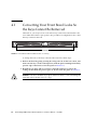
Before you connect the Sun StorEdge 3120 SCSI array to the network, position the
Sun StorEdge 3120 SCSI array in the rack or in the location where it will remain.
Caution – When positioning the array, do not block the air vents at the front or back
of the unit. Follow all safety precautions specified in the Sun StorEdge 3000 Family
Safety, Regulatory, and Compliance Manual.
Caution – When you power off the array, wait five seconds before you power it
back on. If you power the array off and on too quickly, a race condition might occur.
4-1
4.1
Converting Your Front Bezel Locks So
the Keys Cannot Be Removed
The bezel on your array has two locks whose keys can be removed when the locks
are in either the locked or open position. It is possible to reconfigure the locks so that
the keys cannot be removed.
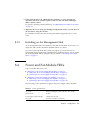
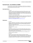
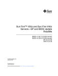
Bezel locks
FIGURE 4-1
Front Bezel and Front Bezel Locks of an Array
To change the locks so the keys cannot be removed, follow these steps:
1. Remove the bezel by gently pivoting the swing arms out of their ear sockets, and
make sure the key is in the locked position, with the pawl extending horizontally
past the edge of the bezel (see the first panel of FIGURE 4-2).
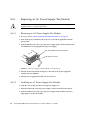
2. Hold the key in place and use a 12 mm or 3/8-inch nut driver to remove the
locking nut that holds the pawl in place as shown in the first panel of FIGURE 4-2.
Caution – Be sure to hold the key in place. Otherwise there is a risk of breaking the
small tab on the lock that serves as a stop.
4-2
Sun StorEdge 3000 Family Installation, Operation, and Service Manual • July 2004
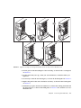
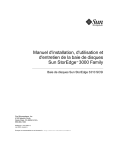
Pawl
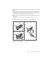
FIGURE 4-2
Sequence of Steps to Change Front Bezel Locks So Keys Cannot Be Removed
3. Lift the pawl off the threaded part of the lock body, as shown in the second panel
of FIGURE 4-2.
4. Set the pawl aside, face up, so that you can remember its orientation when you
replace it.
5. Use the key to turn the lock 180 degrees, as shown in the third panel of FIGURE 4-2.
6. Replace the pawl in the same orientation as before, as shown in the fourth panel
of FIGURE 4-2.
7. Hold the key in place and use the nut driver to refasten the locking nut that holds
the pawl in place, as shown in the fifth panel of FIGURE 4-2. Be careful not to crossthread the nut.
Chapter 4
Connecting Your SCSI Array
4-3
Caution – Be sure to hold the key in place. Otherwise there is a risk of breaking the
small tab on the lock that serves as a stop.
8. Replace the bezel.
Note – To convert your bezel locks back so that the keys can be removed, repeat the
preceding steps.
4.2
Rackmounting the Array
To rackmount the array in a rack or a cabinet, refer to the installation manual which
is provided with the rack or refer to the Sun StorEdge 3000 Family Rack Installation
Guide for 1U Arrays on the product website.
4.3
Connecting Chassis to an AC Power
Outlet
When you connect the AC power cords, you should install the provided two cord
locks at the same time. To connect the AC power cords, perform the following
procedure.
1. Connect an appropriate AC power cable to the first power supply and to a power
outlet.
The provided AC cord locks are used to securely fasten the AC cable connectors.
Caution – For AC power: If the array is connected to AC power sources not within
the designated 90–264 VAC range, damage might occur to the unit.
Note – To ensure power redundancy, be sure to connect the two power supply
modules to two separate circuits (for example, one commercial circuit and one UPS).
2. Use a screwdriver to remove the screw from one of the two cord locks provided.
4-4
Sun StorEdge 3000 Family Installation, Operation, and Service Manual • July 2004
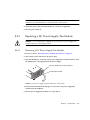
3. Turn the thumbscrew of the green ejector handle counterclockwise to release the
handle.
4. Pull the green ejector handle of the first power supply forward, and slide the cord
lock around the handle and around the AC power connector on the power supply.
The cord lock fits very snugly around the power cable connector.
5. Slide the cord lock screw through the cord lock holes, and tighten the screw with
a screwdriver.
Close the green ejector handle, and turn the thumbscrew clockwise to close the
handle.
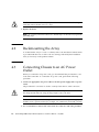
6. Repeat steps 2 through 5 for the second cord lock and second power cable.
Thumbscrew
Latch
FIGURE 4-3
Cord Lock Operation
Chapter 4
Connecting Your SCSI Array
4-5
4.4
Connecting the Chassis to DC Power
Outlets
Two DC power cords are packaged with each DC array. To connect the DC power
cords, perform the following procedure.
1. Connect a DC power cable to the first power supply and to a power outlet.
Note – Use only the DC power cables provided with the array.
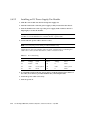
2. Check the DC cable part number and wire labels carefully before connecting the
cable to the source.
TABLE 4-1
DC Cable Wiring for Cable 35-00000148
Pin Number
Voltage
Color
A3
Return
Red
A2
GND (Chassis Ground)
Green/Yellow
A1
-48vdc
Black
TABLE 4-2
DC Cable Wiring for Cable 35-00000156
Pin Number
Voltage
Color
A3
L+
Red
A2
GND (Chassis Ground)
Green/Yellow
A1
L-
White
Caution – If the Sun StorEdge 3120 SCSI array is connected to DC power sources
not within the designated –48V DC (–36 VDC to –72 VDC) range, damage might
occur to the unit.
Note – To ensure power redundancy, be sure to connect the two power supply
modules to two separate circuits (for example, one commercial circuit and one UPS).
4-6
Sun StorEdge 3000 Family Installation, Operation, and Service Manual • July 2004
Note – To extend the length of the DC power cable as needed, strip the last 1/4 inch
of the cable, insert the stripped end into a provided Panduit tube, and crimp the
tube.
3. Tighten the cable locking screws to attach the cable securely to the power supply
power outlet.
4. Connect the second power cable to the second power supply and to a second
power outlet. Tighten the cable locking screws.
If one power supply fails, the second power supply automatically takes the full load.
4.5
Bus and Cable Lengths
The SCSI specification states that the maximum bus length for Ultra320 SCSI is 12
meters for multidrop connections. The Sun StorEdge 3120 SCSI array uses a
multidrop implementation. The ports on each channel are connected to the same
physical SCSI bus.
Taking into account the internal bus length of .7 meters, and the internal SCSI bus
length of the host, the maximum SCSI bus length for each channel is 12 meters when
connected to an LVD host adapter.
You must ensure that the length of all cables to any connected nodes, as well as the
internal bus length of .7 meters internal to the Sun StorEdge 3120 SCSI array and the
internal bus length of the host, is less than 12 meters in total. Also include the
jumper cable length of .3 meters if the JBOD is being used in a single-bus or multiinitiator configuration. In a dual-host, multi-initiator configuration, each host cable
should be 5 meters or less.
The longest Ultra320 cable qualified by Sun is 10 meters in length.
When connected to single-ended host adapters, the longest supported bus length per
channel is 1.5 meters.
Note – If you connect two hosts to the same channel, you must change the scsiinitiator-id of one host adapter as described in the host adapter documentation.
When either of these hosts is subsequently booted, SCSI reset warnings are
displayed on the other host.
Chapter 4
Connecting Your SCSI Array
4-7
4.6
Connecting Sun StorEdge 3120 SCSI
Arrays to Hosts
You can connect a JBOD (Just a Bunch of Disks, no controller) array directly to a Sun
host server using either single-bus or split-bus configurations. With the Sun
StorEdge 3120 SCSI array, you can configure the following:
■
■
■
■
“A Single-Bus JBOD with One Host Connection” on page 4-12
“A Single-Bus, Multi-Initiator JBOD Configuration” on page 4-14
“A Split-Bus, Single-Initiator JBOD Configuration” on page 4-15
“A Split-Bus, Multi-Initiator JBOD Configuration Connected to One JBOD” on
page 4-18
The array can be connected to a host by means of a 320 MB/second PCI Dual
Ultra320 SCSI host adapter installed in a host.
Connect the array to one or two hosts with SCSI cables. The TERM LED is a solid
green color when a drive is available for configuration. For details on the TERM
LED, see “Back-Panel LEDs” on page 6-4.
Note – If you use multiple host servers, they must use the same operating system.
The host server operating system release or version number can differ. For instance,
host server A can run Solaris 8 while host server B runs Solaris 9.
Caution – SCSI IDs are set based on the switch setting on the array when it is
powered on. If you change the switch setting, the SCSI IDs will change after you
power off, and then power on. For more details on switch settings, see “Fixed Drive
IDs” on page 4-10.
Caution – The I/O module is hot-serviceable which means that you can connect or
disconnect its cables while the array is powered on but the SCSI host buses
connected to the array must be inactive.
4-8
Sun StorEdge 3000 Family Installation, Operation, and Service Manual • July 2004
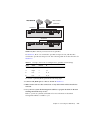
4.6.1
Single-Bus (SB) Label
The drive-bus configuration determines how drives and drive IDs are assigned to
drive channels.
On the rear panel of each unit, the SB icon indicates where to connect the SCSI
jumper cable for a single-bus configuration. The SB icons are located next to the SCSI
ports on the far right and on the far left.
= Single-bus configuration
FIGURE 4-4
Single-Bus Icon
SB icon
FIGURE 4-5
SB icon
Single-Bus Icon as it appears on the rear of the JBOD
Since no SCSI jumper cable is required for a split-bus configuration, there is no
indicator icon.
Note – If a jumper cable is not attached to the JBOD, it is automatically a split-bus
configuration.
The SCSI IDs are also displayed on the lower inside-front edge of the chassis in front
of each drive. These IDs are automatically assigned based on the switch setting. For
more information on switch settings and drive IDs, see the following section, “Fixed
Drive IDs” on page 4-10.
Chapter 4
Connecting Your SCSI Array
4-9
4.6.2
Fixed Drive IDs
Drive IDs are not dependent on the configuration type. Single-bus and split-bus
configurations use the same drive IDs. The IDs assigned for disks 1 through 4
depend on the switch settings on the JBOD array. IDs 5 and 6 are reserved for SAFTE IDs. The fixed drive IDs for a 4-drive configuration are shown in FIGURE 4-6.
ID 8 ID 12
ID 9 ID 13
ID 10 ID 14
ID8
ID9
ID10
ID12
FIGURE 4-6
ID 10 ID 14
ID 9 ID 13
ID 8 ID 12
ID13
ID14
ID 11 ID 15
Right switch set
ID11
ID 11 ID 15
Left switch set
ID15
Drive IDs for Single-Bus and Split-Bus Configurations
Caution – SCSI IDs are set based on the switch setting on the array when it is
powered on. If you change the switch setting, the SCSI IDs will change after you
power off, and then power on.
The following table shows the drive IDs that correspond with the switches in
FIGURE 4-6.
TABLE 4-3
4-10
Switch Settings and Drive IDs for Single-Bus and Split-Bus Configurations
Drive IDS
SAF-TE ID
Right Switch
8, 9, 10, 11
5
Left Switch
12, 13, 14, 15
6
Sun StorEdge 3000 Family Installation, Operation, and Service Manual • July 2004
Note – Each device in your SCSI configuration must have a unique ID. For instance,
if your HBA device uses ID 6, do not use the left-switch setting, which sets the SAFTE ID to 6. Use the right-switch setting.
The IDs are also displayed on the lower inside-front edge of the chassis in front of
each drive. These IDs are automatically assigned based on the switch setting as
shown in FIGURE 4-6.
The following illustration shows the port names. The port names, A and B, are used
for easy reference in the cabling procedures. In a single-bus configuration, the B Out
and the A In ports are available for host connections. For more information, see “A
Single-Bus JBOD with One Host Connection” on page 4-12 or “A Single-Bus, MultiInitiator JBOD Configuration” on page 4-14. In a split-bus configuration, several host
connection configurations exist. For details, see “A Split-Bus, Single-Initiator JBOD
Configuration” on page 4-15 or “A Split-Bus, Multi-Initiator JBOD Configuration
Connected to One JBOD” on page 4-18.
B In
FIGURE 4-7
4.6.3
B Out
A In
A Out
Sun StorEdge 3120 SCSI Array Port Names
Connecting Cables for a Single-Bus Configuration
A single-bus I/O configuration assigns all disk drive IDs in a chassis to one channel.
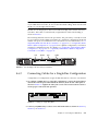
1. To configure a JBOD unit as a single-bus configuration, connect the SCSI jumper
cable between SCSI ports labeled with the SB icon, the B In and A Out ports as
shown in FIGURE 4-7. Tighten the cable jack screws with six full clockwise turns to
ensure proper connection and operation.
FIGURE 4-8
Cabling for Single-Bus JBOD
2. Connect your JBOD array to a host server with SCSI cables as shown in FIGURE 4-8,
FIGURE 4-9, or FIGURE 4-10.
Chapter 4
Connecting Your SCSI Array
4-11
Caution – When you connect the host cable in single-bus configuration, attach the
host cable in a way that does not bend or damage the jumper cable.
4.6.4
A Single-Bus JBOD with One Host Connection
Caution – BEFORE you disconnect a cable from the array, the host bus on that cable
must be inactive.
Caution – When you connect the host cable in single-bus configuration, attach the
host cable in a way that does not bend or damage the jumper cable.
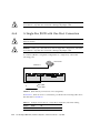
To connect a JBOD in a single-bus configuration to a single host, connect the
following ports:
Host server
Channel 1
Bus cable
Host cable
FIGURE 4-9
JBOD Directly Connected to a Host (Single-Bus)
In FIGURE 4-9, the host server is connected to port B Out. The following table shows
the drive IDs for FIGURE 4-9.
4-12
TABLE 4-4
Example of Drive IDs for a Single Host, Single-Bus, Left-Switch Setting
Channel
Switch
ID
1
Left
12, 13, 14, 15
Sun StorEdge 3000 Family Installation, Operation, and Service Manual • July 2004
To connect multiple JBODs in a single-bus configuration to a single host, connect the
following ports:
Host server
Channel 1
Channel 2
Bus cable
Host cable
FIGURE 4-10
Multiple JBODs Directly Connected to a Host (Single-Bus)
In FIGURE 4-10, the host server is connected to port B Out. The following table shows
the drive IDs for FIGURE 4-10.
TABLE 4-5
Example of Drive IDs for a Single Host, Single-Bus Switch Settings
Channel
Switch
ID
1
Left
12, 13, 14, 15
2
Right
8, 9, 10, 11
Chapter 4
Connecting Your SCSI Array
4-13
4.6.5
A Single-Bus, Multi-Initiator JBOD Configuration
A dual-host, single-bus multi-initiator configuration primarily works in conjunction
with multi-initiator software such as Sun Cluster or Veritas Cluster. In this
configuration, each host server is connected to each host channel. Without the multiinitiator software, the host servers can write to the same drive simultaneously which
may overwrite data.
You can configure a non-cluster dual-host, single-bus environment, but you must
ensure that the hosts write to different disks on the SCSI bus by setting up a special
configuration. For instance, you can specifically configure which host writes to each
disk to prevent data overwrites.
Note – Each device in your configuration must have a unique ID, including any
HBA devices. For instance, if your HBA device uses ID 6, do not use the left-switch
setting, which sets the SAF-TE ID to 6. For details on setting the HBA device ID, see
“Enabling VERITAS DMP in a Single-Bus Configuration” on page 5-17.
Caution – BEFORE you disconnect a cable from the array, the host bus on that cable
must be inactive.
Caution – When you connect the host cable in single-bus configuration, attach the
host cable in a way that does not bend or damage the jumper cable.
4-14
Sun StorEdge 3000 Family Installation, Operation, and Service Manual • July 2004
To connect a JBOD in a single-bus configuration to dual hosts, connect the following
ports:
Host server B
Host server A
Channel 1
Channel 2
Bus cable
Host cable
FIGURE 4-11
JBOD Directly Connected to Two Hosts (Single-Bus)
In FIGURE 4-11, Host A is connected to port B Out and Host B is connected to port A
In. The following table shows the drive IDs for FIGURE 4-11.
4.6.6
TABLE 4-6
Example of Drive IDs for Dual Hosts, Single-Bus, Right-Switch Setting
Server
Channel
Switch
ID
A
1
Right
8, 9, 10, 11
B
2
Right
8, 9, 10, 11
A Split-Bus, Single-Initiator JBOD Configuration
There are two important features to note with the split-bus, single-initiator mode
JBOD configuration:
■
Connect one A and one B input port on the JBOD with an HBA host connection to
the host. The I/O SCSI connectors are auto-terminated.
■
In a split-bus configuration, the SCSI ID numbers automatically change according
to the switch settings. For more informations on switch settings, see “Fixed Drive
IDs” on page 4-10.
Single-initiator mode is when there is only one host connection on a SCSI channel.
Chapter 4
Connecting Your SCSI Array
4-15
Caution – BEFORE you disconnect a cable from the array, the host bus on that cable
must be inactive.
FIGURE 4-12 shows a split-bus JBOD with two host connections, one host connection
to each channel (single-initiator mode). This is an efficient way to provide mirroring
capability for a single host.
Note – You can connect the cables to the inboard or outboard ports on a JBOD. Both
configurations work. FIGURE 4-12 shows the cables connected to the outboard ports.
Host server
HBA 1
Channel 1
FIGURE 4-12
HBA 2
Channel 2
JBOD Directly Connected to a Host (Split-Bus)
In FIGURE 4-12, HBA 1 is connected to port B In and HBA 2 is connected to port A
Out. The following table shows the drive IDs for FIGURE 4-12.
TABLE 4-7
Example of Drive IDs for a Single Host, Split-Bus, Left-Switch Setting
HBA
Channel
Switch
ID
1
1
Left
14, 15
2
2
Left
12, 13
FIGURE 4-13 shows multiple hosts with multiple JBODs in a split-bus JBOD
configuration with two host connections, one host connection to each channel
(single-initiator mode). This is an efficient way to provide mirroring capability.
Note – You can connect the cables to the inboard or outboard ports on a JBOD. Both
configurations work. FIGURE 4-13 shows the cables connected to the outboard ports
on the upper JBOD and the cables connected to the inboard ports on the lower
JBOD.
4-16
Sun StorEdge 3000 Family Installation, Operation, and Service Manual • July 2004
Host server A
Host server B
Channel 4
Channel 1
Channel 2
Channel 3
FIGURE 4-13
JBODs Directly Connected to Hosts (Split-Bus)
In FIGURE 4-13, Host A is connected to port B In and port A Out, and Host B is
connected to port B Out and port A In. The following table shows the drive IDs for
FIGURE 4-13.
TABLE 4-8
Example of Drive IDs for Multiple Hosts, Split-Bus Switch Settings
Server
Switch
Channel
ID
A
Right
1
10, 11
A
Right
2
8, 9
B
Left
3
14, 15
B
Left
4
12, 13
To connect a split-bus JBOD, perform the following steps.
1. Connect each JBOD port to a host as shown in FIGURE 4-13.
2. Make inactive the host bus connections of any cable which will be installed or
removed.
3. Use your host system disk management utilities to prepare the disks in the Sun
StorEdge 3120 SCSI array for use.
Refer to your host system documentation for more information about disk
management utilities available to you.
Chapter 4
Connecting Your SCSI Array
4-17
4.6.7
A Split-Bus, Multi-Initiator JBOD Configuration
Connected to One JBOD
A dual-host, split-bus, multi-initiator configuration primarily works in conjunction
with multi-initiator software such as Sun Cluster or Veritas Cluster. In this
configuration, each host server is connected to two host channels. Without the multiinitiator software, the host servers can write to the same drive simultaneously which
may overwrite data.
You can configure a non-cluster dual-host, split-bus, multi-initiator environment, but
you must ensure that the hosts write to different disks on the SCSI bus by setting up
a special configuration. For instance, you can specifically configure which host
writes to each disk to prevent data overwrites.
Caution – BEFORE you disconnect a cable from the array, the host bus on that cable
must be inactive.
To connect a JBOD in a split-bus configuration to two hosts, connect the following
ports:
Host server A
Host server B
Channel 3
Channel 1
FIGURE 4-14
Channel 2
Channel 4
Dual-Host, Multi-Initiator Array Connected to a Single JBOD
In FIGURE 4-14, Host A is connected to port B In and to port A In. Host B is connected
to port B Out and to port A Out. This configuration is common for failover
protection in a network cluster environment.
4-18
Sun StorEdge 3000 Family Installation, Operation, and Service Manual • July 2004
The following table shows the drive IDs for FIGURE 4-14.
TABLE 4-9
Example of Drive IDs for Multiple Hosts in a Dual-Initiator Configuration
with a Left-Switch Setting
Server
Switch
Channel
ID
A
Left
1
14, 15
A
Left
2
12, 13
B
Left
3
14, 15
B
Left
4
12, 13
Chapter 4
Connecting Your SCSI Array
4-19
4-20
Sun StorEdge 3000 Family Installation, Operation, and Service Manual • July 2004
CHAPTER
5
Software Management Tools
This chapter describes the software management tools used for monitoring and
managing the Sun StorEdge 3120 SCSI array. Topics include the following:
■
“Overview of Provided Software” on page 5-1
■
“Monitoring with the Sun StorEdge Configuration Service” on page 5-2
■
“Event Messages from the Sun StorEdge Diagnostic Reporter” on page 5-6
■
“Monitoring with the Sun StorEdge CLI” on page 5-7
■
“Managing Disks in the Sun StorEdge 3120 SCSI Array” on page 5-17
■
“Enabling VERITAS DMP in a Single-Bus Configuration” on page 5-17
Note – For other supported software, see the Release Notes for your array.
5.1
Overview of Provided Software
This section describes the software management tools available for monitoring and
managing the Sun StorEdge 3120 SCSI array with in-band connections.
The following software management tools are provided on the Sun StorEdge 3000
Family Professional Storage Manager CD, provided with your array. The Sun
StorEdge 3000 Family Documentation CD provides the related user guides.
■
Sun StorEdge Configuration Service. Provides monitoring functions. Refer to the
Sun StorEdge 3000 Family Configuration Service User’s Guide for in-band setup
procedures.
■
Sun StorEdge Diagnostic Reporter. Provides event monitoring and notification.
Refer to the Sun StorEdge 3000 Family Diagnostic Reporter User’s Guide for
information.
5-1
■
Sun StorEdge Command-Line Interface (CLI). A command-line interface utility
that provides script-based management. Refer to the Sun StorEdge 3000 Family CLI
User’s Guide for additional CLI information.
For details on how to install Sun StorEdge Configuration Service, Sun StorEdge
Diagnostic Reporter, or the Sun StorEdge CLI software, refer to the Sun StorEdge
3000 Family Software Installation Manual.
5.2
Monitoring with the Sun StorEdge
Configuration Service
Sun StorEdge Configuration Service supports standalone JBOD arrays. However,
because the Sun StorEdge 3120 SCSI array does not have a RAID controller or RAID
controller firmware to manage the disks, this software support is limited to enabling
JBOD support and viewing component and alarm characteristics.
See “Viewing Component and Alarm Characteristics” on page 5-4.
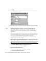
5.2.1
Enabling JBOD Support
Use JBOD support only when you have a SCSI array connected directly to a host.
This enables you to monitor peripheral device condition and events.
Note – Enabling JBOD support may impact I/O performance.
To monitor peripheral device condition and events for a JBOD device from the Sun
StorEdge Configuration Service Console, you first need to enable JBOD support.
1. Select View → Agent Options Management.
The Agent Options Management window is displayed.
2. Select the Enable JBOD Support check box.
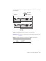
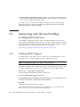
3. To immediately display the JBOD in the main window, you need to probe for new
inventory. Select View → View Server and click Probe.
4. Click OK.
The JBOD is displayed in the main window.
In a single-bus configuration, both ports of the JBOD array are connected to one
HBA on the server, as shown in the following example.
5-2
Sun StorEdge 3000 Family Installation, Operation, and Service Manual • July 2004
FIGURE 5-1
Single-Bus Configuration
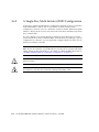
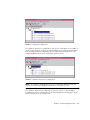
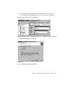
In a split-bus, dual-server configuration, each port is connected to its own HBA, as
shown in the following example. A SAF-TE limitation prevents the main window
from showing the drives connected to port A and port B. The program can only
monitor the JBOD from the server connected to port B as shown
FIGURE 5-2
Split-Bus, Dual-Server Configuration
Note – In a split-bus configuration, if each port is connected to different servers, the
program can only monitor the JBOD from the server connected to port B.
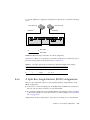
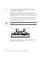
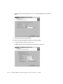
In a split-bus, single-server configuration, shown in FIGURE 5-3, Sun StorEdge
Configuration Service compensates for the SAF-TE limitation and displays all the
drives connected to port A and port B.
Chapter 5
Software Management Tools
5-3
FIGURE 5-3
5.2.2
Split-Bus, Single-Server, Dual HBA Configuration
Viewing Component and Alarm Characteristics
In Sun StorEdge Configuration Service, to view environmental component and
alarm characteristics, use the View Enclosure window or, for some components, the
main window.
You can also view environmental and drive components using the Sun StorEdge
CLIL show enclosure-status command. For details, see “show enclosurestatus” on page 5-12.
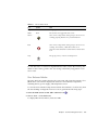
Main Window
In the main window, device states are color-coded and symbol-coded so that it is
easy to identify when a device is in a state that requires attention. The status is
propagated along the device tree, enabling you to trace a failure down to the device
level. See TABLE 5-1 for device status details.
5-4
Sun StorEdge 3000 Family Installation, Operation, and Service Manual • July 2004
TABLE 5-1
Device Status State
Color
Symbol
State
Purple
None
The group, server, or device is online.
White
None
The user has not logged into this server.
Yellow
One or more components of this group or server are not
working properly, but the array is still functional.
Red
One or more components of this group or server are not
working. For instance, a disk drive failure or an
enclosure with a failed fan would warrant a critical state
icon.
Gray
The group, server, or device is unresponsive.
?
To view the cause of a critical or degraded device status, review the event log. For
details on the event log, refer to the Sun StorEdge 3000 Family Configuration Service
User’s Guide.
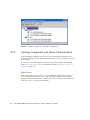
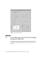
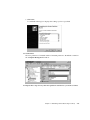
View Enclosure Window
The View Enclosure window displays the component and alarm characteristics for a
JBOD device. The window displays the status for environmental components
including the fan, power supply, and temperature sensor.
To view the environmental component and alarm characteristics of a SCSI array from
the Sun StorEdge Configuration Service Console, perform the following steps.
1. Select the EMU (SCSI) or SES (Fibre Channel) icon
.
2. Choose View → View Enclosure.
To display FRU ID information, click View FRU.
Chapter 5
Software Management Tools
5-5
FIGURE 5-4
5.3
View Enclosure Dialog Box
Event Messages from the Sun StorEdge
Diagnostic Reporter
Sun StorEdge Diagnostic Reporter supports standalone JBOD arrays. However,
triggered event notification is limited to environmental and hard drive failures.
Refer to the Sun StorEdge 3000 Family Diagnostic Reporter User’s Guide for more
information.
5-6
Sun StorEdge 3000 Family Installation, Operation, and Service Manual • July 2004
5.4
Monitoring with the Sun StorEdge CLI
The Sun StorEdge CLI supports JBOD arrays. However, because JBOD arrays do not
have a RAID controller or RAID controller firmware to manage the disks, this CLI
support is limited to the following sccli commands:
■
■
■
■
■
■
■
■
■
■
■
■
■
about
exit
help
quit
select
set led
show configuration
show enclosure-status
show frus
show inquiry-data
show led-status
show safte-devices
version
about
The about command displays version and copyright information.
about
The following example shows the about text for the CLI:
sccli> about
Sun StorEdge 3000 Family CLI
Copyright 2002 Dot Hill Systems Corporation.
All rights reserved. Use is subject to license terms.
sccli version 1.6.0
built 2004.01.26.23.49
exit
This command exits the interactive mode.
exit
Chapter 5
Software Management Tools
5-7
help
The help command displays a short synopsis of the available commands.
help [command]
If no command is specified, basic usage information is displayed.
quit
The quit command exits the interactive mode.
quit
select
The select command selects a new device to which subsequent commands are
issued. If no device is specified, and more than one choice exists, a menu of choices
is displayed. This command should not be used on the command line because a
select command is implicitly done if no device name is specified.
select device
The following command selects an in-band SCSI JBOD device.
sccli> select /dev/es/ses0
sccli: selected device /dev/es/ses2 [SUN StorEdge 3120 D SN#00029F]
5-8
Sun StorEdge 3000 Family Installation, Operation, and Service Manual • July 2004
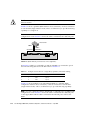
set led
This command illuminates the LED in the enclosure adjacent to the specified disk (or
slot). For JBODs, specify a disk device using a Solaris device name such as sd31 or
c1t0d0s2, or specify a slot number. Use the show led-status command to show
the status of the identified disk drive.
Note – Selecting a slot by disk name is not supported in split-bus (dual-bus)
enclosure configurations because the enclosure services processor resides on only
one of the internal buses and the CLI may not be able to unambiguously determine
the slot location of a particular device. In such configurations, use the show
enclosure-status command and the documentation provided with your
enclosure to determine the correct slot number instead.
To illuminate a disk drive LED, use the following parameters:
set led {slot n | disk sdn | disk cXtYdZ} {on | off}
In the following example, the LED adjacent to the drive with SCSI address 3 in the
enclosure is set to on:
sccli> set led slot 3 on
(enclosure sn 006498) led-slot-3: on
TABLE 5-2
Arguments for set led
Argument
Description
slot n
Illuminates the drive LED for specified disk drive slot.
disk sdn
Illuminates the drive LED for the specified Solaris disk drive slot.
disk cXtYdZ
Illuminates the drive LED for the specified Solaris disk drive slot.
ch.id
Illuminates the drive LED for the specified drive within a RAID
subsystem.
{on | off}
Specify whether to illuminate the drive LED.
Chapter 5
Software Management Tools
5-9
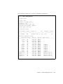
show configuration
This command displays the array configuration including inquiry information, FRU
information, and the enclosure status which includes the status for the fan, power
supply, temperature sensor, and drive slots. The configuration can be displayed
onscreen, or written to the specified file. The output is plain text by default, but
XML output may be obtained by specifying the --xml option.
show configuration [--xml | -x] [filename]
TABLE 5-3
Arguments for show configuration
Argument
Description
{--xml | -x}
If the -x or --xml options are specified, XML output is generated.
filename
Specify the filename for the configuration file that you want to
show.
Enclosure status values include:
Status
Description
OK
This component has a status of OK.
Absent
This component is absent.
Fault
The component is exhibiting a fault condition.
Unknown
This component status is not available.
The following example writes the configuration information to the myconfig.xml
file.
# sccli c2t0d0 show configuration --xml myconfig.xml
5-10
Sun StorEdge 3000 Family Installation, Operation, and Service Manual • July 2004
The following example shows a portion of the JBOD configuration.
sccli> show configuration
* inquiry-data
Vendor: SUN
Product: StorEdge 3120 D
Revision: 1159
Peripheral Device Type: 0x3
Page 80 Serial Number: 006498
Device Type: Enclosure
* enclosure-status
Id Chassis Vendor Product ID
Rev
Package
Status
-------------------------------------------------------------6 006498
SUN
StorEdge 3120 D 1159 1159
OK
Enclosure Component Status:
Type Unit Status
FRU P/N
FRU S/N
Add'l Data
---------------------------------------------------------------Fan 0
OK
370-5638 000236
-Fan 1
OK
370-5638 000287
-PS 0
OK
370-5638 000236
-PS 1
OK
370-5638 000287
-Temp 0
OK
370-6195 006498
temp=31
Temp 1
OK
370-6195 006498
temp=30
Temp 2
OK
370-5638 000236
temp=28
Temp 3
OK
370-6195 006498
temp=31
Temp 4
OK
370-6195 006498
temp=30
Temp 5
OK
370-6195 006498
temp=30
Temp 6
OK
370-5638 000287
temp=28
DiskSlot 0
OK
370-6195 006498
addr=12,led=off
DiskSlot 1
OK
370-6195 006498
addr=13,led=off
DiskSlot 2
OK
370-6195 006498
addr=14,led=off
DiskSlot 3
OK
370-6195 006498
addr=15,led=off
...
Chapter 5
Software Management Tools
5-11
show enclosure-status
The show enclosure-status command shows the status for all chassis
components including SAF-TE information, fan, power supply, temperature sensor,
and drive slot status.
Note – In split-bus configurations, half the drives display a status of Absent. The
drives are present, but because of a SAF-TE design limitation, the information does
not display.
show enclosure-status
Enclosure status values include:
Status
Description
OK
This component has a status of OK.
Absent
This component is absent.
Fault
The component is exhibiting a fault condition.
Unknown
This component status is not available.
Disk slots refer to the backplane FRU to which disks are connected.
Note – The Enclosure SCSI Channel Type values include single-bus and split-bus.
Throughout the documentation and the CLI, the term “split-bus” is interchangeable
with the term “dual-bus.” For details on configuring an array, see “Connecting Sun
StorEdge 3120 SCSI Arrays to Hosts” on page 4-8.
5-12
Sun StorEdge 3000 Family Installation, Operation, and Service Manual • July 2004
The following example shows the enclosure status for a Sun StorEdge 3120 SCSI
device.
sccli> show enclosure-status
Id Chassis Vendor Product ID
Rev
Package
Status
-------------------------------------------------------------6 006498
SUN
StorEdge 3120 D 1159 1159
OK
Enclosure Component Status:
Type Unit Status
FRU P/N
FRU S/N
Add'l Data
---------------------------------------------------------------Fan 0
OK
370-5638 000236
-Fan 1
OK
370-5638 000287
-PS 0
OK
370-5638 000236
-PS 1
OK
370-5638 000287
-Temp 0
OK
370-6195 006498
temp=30
Temp 1
OK
370-6195 006498
temp=30
Temp 2
OK
370-5638 000236
temp=30
Temp 3
OK
370-6195 006498
temp=30
Temp 4
OK
370-6195 006498
temp=30
Temp 5
OK
370-6195 006498
temp=30
Temp 6
OK
370-5638 000287
temp=28
DiskSlot 0
OK
370-6195 006498
addr=12,led=off
DiskSlot 1
OK
370-6195 006498
addr=13,led=off
DiskSlot 2
OK
370-6195 006498
addr=14,led=off
DiskSlot 3
OK
370-6195 006498
addr=15,led=off
Enclosure SCSI Channel Type: single-bus
show frus
This command displays field-replaceable units (FRU) ID and status information. All
FRU information is retrieved from the SAF-TE device.
show frus
FRU status values include:
Status
Description
OK
All subcomponents of this FRU have a status of OK.
Fault
One or more of the FRU components is exhibiting a fault condition.
Chapter 5
Software Management Tools
5-13
The following examples return all FRU information for the JBOD unit:
# sccli c2t0d0 show frus
# sccli /dev/scsi/processor/c6t15d0 show frus
The following example shows a partial list of the FRUs in a Sun StorEdge 3120 SCSI
device:
sccli> show frus
3 FRUs found in chassis SN#006498
Name: JBOD_CHASSIS_BKPLN
Description: SE3120 JBOD Chassis
Part Number: 370-6195
Serial Number: 006498
Revision: 01
Manufacturing Date: Thu Jan 15 07:33:19 2004
Manufacturing Location: Milpitas California, USA
Manufacturer JEDEC ID: 0x0301
FRU Location: 1U SCSI JBOD MIDPLANE SLOT
Chassis Serial Number: 006498
FRU Status: OK
Name: AC_POWER_SUPPLY
Description: SE3110 AC PWR SUPPLY/FAN MOD
Part Number: 370-5638
Serial Number: 000236
Revision: 01
Manufacturing Date: Tue Jul 8 22:14:33 2003
Manufacturing Location: Irvine California, USA
Manufacturer JEDEC ID: 0x048F
FRU Location: 1U AC PSU SLOT #0 (LEFT)
Chassis Serial Number: 006498
FRU Status: OK
Name: AC_POWER_SUPPLY
Description: SE3110 AC PWR SUPPLY/FAN MOD
Part Number: 370-5638
Serial Number: 000287
. . .
5-14
Sun StorEdge 3000 Family Installation, Operation, and Service Manual • July 2004
show inquiry-data
This command displays the SCSI inquiry data. The output of this command varies
from one product to another, and from one channel to another.
show inquiry-data
The following example shows an in-band Sun StorEdge 3120 SCSI array inquiry.
sccli>
show inquiry-data
Vendor: SUN
Product: StorEdge 3120 D
Revision: 1159
Peripheral Device Type: 0x3
Page 80 Serial Number: 006498
Device Type: Enclosure
show led-status
This command displays the status of the LED adjacent to the specified disk drive slot
in the array enclosure or expansion chassis.
To show the status of LVD JBOD enclosures, use the following parameters:
show led-status {slot n | disk sdn | disk cXtYdZ}
The following example shows the status of the LED adjacent to the disk assigned to
drive slot 3 for an expansion chassis:
sccli> show led-status slot 3
(enclosure sn 006498) led-slot-3: on
Chapter 5
Software Management Tools
5-15
TABLE 5-4
Arguments for show led-status
Argument
Description
slot n
Shows the status for the LED adjacent to the specified disk drive
slot. This argument is not accepted for RAID controllers.
disk sdn
Shows the status for the LED adjacent to the specified Solaris disk
drive slot. This argument is not accepted for split-bus chassis.
disk cXtYdZ
Shows the status for the LED adjacent to the specified Solaris disk
drive slot. This argument is not accepted for split-bus chassis.
ch.id
Shows the status for the LED adjacent to the specified drive within a
RAID subsystem.
show safte-devices
This command displays information returned by the SAF-TE device embedded in
SCSI LVD RAID enclosures or JBODs.
The output includes the serial number of the chassis in which it is installed, the
vendor and product IDs and SAF-TE firmware revision, and the “SAF-TE firmware
package” revision, which refers to firmware for other microprocesses in the chassis
that are managed by the SAF-TE processor.
show safte-devices
The following example shows the SAF-TE device information for a Sun StorEdge
3120 SCSI array.
sccli> show safte-devices
Id Chassis Vendor Product ID
Rev
Package
-----------------------------------------------------6 006498
SUN
StorEdge 3120 D 1159 1159
5-16
Sun StorEdge 3000 Family Installation, Operation, and Service Manual • July 2004
version
The version command displays the version number of the CLI.
version
For example:
sccli> version
sccli version 1.6.0
5.5
Managing Disks in the Sun StorEdge
3120 SCSI Array
Use your standard host system disk management utilities for all disk management in
a JBOD array, such as partitioning and formatting. Refer to your host system
documentation for more information about disk management.
For maintenance and troubleshooting information, see “Maintaining and
Troubleshooting Your Array” on page 7-1.
5.6
Enabling VERITAS DMP in a Single-Bus
Configuration
The Sun StorEdge 3120 SCSI array supports Veritas Dynamic Multi-Pathing (DMP)
software.
Note – For other supported software, see the Release Notes for your array.
To enable VERITAS Dynamic Multi-Pathing (DMP) support on VERITAS Volume
Manager Version 3.2, ensure the HBA device SCSI initiator IDs are unique and then
start the system. Perform the following steps.
Chapter 5
Software Management Tools
5-17
1. Create a single-bus, multi-initiator configuration that links two cables to two
different HBAs.
For details about creating a single-bus multi-initiator configuration, see “A SingleBus, Multi-Initiator JBOD Configuration” on page 4-14.
2. Stop the server and at the ok prompt, type:
ok setenv auto-boot? false
ok reset-all
ok probe-scsi-all
3. Issue the remaining commands on only one of the paths.
4. Edit or create the nvramrc to set the SCSI-initiator-id to a non-conflicting ID for
these devices based on the information returned in step 2.
5. From the OBP type:
ok
0:
1:
2:
3:
4:
nvedit
probe-all install-console banner
cd /pci@6,4000/scsi@3 *** your path information here ***
6 " scsi-initiator-id" integer-property
device-end
banner (Ctrl-c)
6. Press Ctrl-c, and store the nvramrc by typing:
ok nvstore
7. Set the system to use the nvramrc and reset auto-boot by typing:
ok setenv use-nvramrc? true
ok setenv auto-boot? true
8. Reset the configuration by typing:
ok reset-all
9. Reboot the hosts. A system reboot is required to implement these changes.
5-18
Sun StorEdge 3000 Family Installation, Operation, and Service Manual • July 2004
Note – SCSI arrays require a license from VERITAS in order to enable any of its
advanced features. Refer to VERITAS Volume Manager Release Notes or contact
VERITAS Software Corporation for licensing terms and information.
Chapter 5
Software Management Tools
5-19
5-20
Sun StorEdge 3000 Family Installation, Operation, and Service Manual • July 2004
CHAPTER
6
Checking LEDs
This chapter describes the front-panel and back-panel LEDs, which give the clear
status of the operation of all drives and modules. Topics covered in this chapter
include:
■
■
■
6.1
“LEDs When Array Is First Powered On” on page 6-1
“Front-Panel LEDs” on page 6-2
“Back-Panel LEDs” on page 6-4
LEDs When Array Is First Powered On
With the array powered on without the SCSI bus configuration cable installed while
the array is not connected to a server, you should see the LED conditions described
in TABLE 6-1 and TABLE 6-2.
TABLE 6-1
Front-Panel LED Status When Array Is First Powered On
Drive LEDs
Solid green
Chassis ear LEDs
Solid green
TABLE 6-2
Back-Panel LED Status When Array Is First Powered On
I/O Module:
ERROR LED
Blinking green (no bus configuration; invalid state)
TERM LED
Solid green (autotermination enabled)
Inactive (no bus configuration; invalid state)
Power/fan module LEDs
Solid green
6-1
6.2
Front-Panel LEDs
The drive LEDs are located between the rows of drives on the front panel (see the
following figure). The system operation LEDs are located on the right ear of the
chassis.
Power/Fan
Drive LEDs
Temp
Event
Reset button
Disk 1
Disk 2
ID 0
ID 1
Disk 3
ID 2
Disk 4
ID 3
Drive LEDs
FIGURE 6-1
Front-Panel LEDs
The following figure shows the front-panel LEDs and Reset button.
Use the Reset button to silence an alarm. For alarm details, see “Silencing Audible
Alarms” on page 7-3.
6-2
Sun StorEdge 3000 Family Installation, Operation, and Service Manual • July 2004
Power/Fan
Temp
Event
Reset button
FIGURE 6-2
Chassis Ear LEDs and Reset Button on Front Panel
The following table lists the front-panel LEDs.
TABLE 6-3
Front Panel LEDs
LED
LED Color
Description
Drive
Solid green
Blinking green
Solid amber
Good: Drive power-up and spin-up OK.
Good: Drive activity.
Failed: Drive failure.
Solid green
Solid amber
Power supply good.
Failed: One or more output voltages out of range.
Solid green
Solid amber
Good: Under temperature threshold of 55C.
Failed: Temperature threshold equal to or
over 55C.
Solid green
Solid amber
Normal operation.
Abnormal environment event.
Power (Light bulb icon)
Monitors the DC output voltage
within tolerance specification.
Overcurrent protection shutting
down any voltage output
displayed.
Voltage thresholds:
+5 VDC +/–.25 VDC
+12 VDC +/–.6 VDC
Current thresholds:
+5 VDC 20A
+12 VDC 12A
Temp (Thermometer icon)
Monitors the temperature level
and indicates violations of internal
temperature thresholds of 55C and
60C.
Event (Caution icon)
Indicates any abnormal or failure
event.
Chapter 6
Checking LEDs
6-3
Note – To test that the front-panel LEDs work, press and hold the Reset button for 5
seconds. All the LEDs should change from green to amber when you perform this
test. Any LED that fails to light indicates a problem with the LED. When you release
the Reset button, the LEDs return to their initial state.
6.3
Back-Panel LEDs
The back-panel LED colors indicate the conditions described in the following figures
and tables. The following figure is the back-panel with LEDs.
FIGURE 6-3
6-4
Back-Panel LEDs
Sun StorEdge 3000 Family Installation, Operation, and Service Manual • July 2004
TABLE 6-4
Back-Panel Module LEDs
Module
Power supply/fan
Monitors the DC output voltage within
tolerance specification. Overcurrent
protection shutting down any voltage output
will also be displayed.
Voltage thresholds:
+5 VDC +/–.25 VDC
+12 VDC +/–.6 VDC
Current Thresholds:
+5 VDC
20A
+12 VDC
12A
I/O module
TERM LEDs
ERROR LED
LED Color
Status
Solid green
Solid amber
Solid green
Solid amber
Power supply good.
Failed: one or more output voltages
out of range.
Good fan: Over 900 RPM.
Faulty/failed: Under 900 RPM.
Solid green
Inactive LED
Autotermination enabled.
Autotermination disabled.
Blinking green
Solid amber
Inactive LED
Invalid single- or dual-cable
configuration.
Failed I/O module.
Valid single- or split-bus
configuration, and I/O module is
good.
Caution – If you see a blinking green or amber LED, you might have an incorrect
configuration or a failed component.
The AC and DC power supply and fan modules have a single LED.
FIGURE 6-4
AC Power Supply and Fan Module
Chapter 6
Checking LEDs
6-5
FIGURE 6-5
DC Power Supply and Fan Module
The I/O modules for JBOD units have TERM and ERROR LEDs.
TERM LED
TERM LED
TERM LED TERM LED
ERROR LED
FIGURE 6-6
6-6
JBOD I/O Module
Sun StorEdge 3000 Family Installation, Operation, and Service Manual • July 2004
CHAPTER
7
Maintaining and Troubleshooting
Your Array
This chapter describes troubleshooting procedures and error messages you can use
to isolate configuration and hardware problems as well as maintenance procedures.
This chapter covers the following topics:
■
“Upgrading Firmware” on page 7-2
■
“Failed Component Alarms” on page 7-2
■
“Silencing Audible Alarms” on page 7-3
■
“General Troubleshooting Guidelines” on page 7-4
■
“Writing Events to a Log File for an IBM AIX Host” on page 7-5
■
“Troubleshooting Solaris Operating System Configuration Issues” on page 7-6
■
“JBOD Disks Not Visible to the Host” on page 7-6
■
“Making JBODs Visible to Hosts Running the Solaris Operating System” on
page 7-7
■
“Making JBODs Visible to Hosts Running the Windows NT Operating System”
on page 7-7
■
“Making JBODs Visible to Hosts Running the Windows 2000 and Windows
2003 Operating Systems” on page 7-10
■
“Making JBODs Visible to Hosts Running the Linux Operating System” on
page 7-14
■
“Making JBODs Visible to Hosts Running the HP-UX Operating System” on
page 7-15
■
“Making JBODs Visible to Hosts Running the IBM AIX Operating System” on
page 7-15
“Identifying a Failed Drive for Replacement” on page 7-17
■
“Verifying Operating System Device Information” on page 7-17
■
“JBOD Troubleshooting Decision Trees” on page 7-19
■
7-1
To check front-panel and back-panel LEDs, see “Checking LEDs” on page 6-1.
For more troubleshooting tips, refer to the Sun StorEdge 3120 SCSI Release Notes at:
http://www.sun.com/products-nsolutions/hardware/docs/Network_Storage_Solutions/Workgroup/3120
7.1
Upgrading Firmware
Firmware upgrades are made available as patches that you can download from the
Sun web site, located at:
http://sunsolve.Sun.COM
Each patch applies to a particular type of firmware, including:
■
■
Drive firmware
SAF-TE firmware (SCSI only)
Each patch includes an associated README text file that provides detailed
instructions about how to download and install that patch. Firmware downloads
follow the same general steps:
■
■
■
7.2
Locating the patch that contains the firmware upgrade you want.
Downloading the patch to a location on your network.
Following the directions in the README patch text file to load the firmware
upgrade.
Failed Component Alarms
Failed component alarm tones use Morse code dot and dash characters. The dot “.”
is a short tone sounding for one unit of time. The dash “-” is a long tone sounding
for three units of time.
Alarms, also referred to as beep codes, are presented in a sequence, starting with the
critical component failure alarm, which alerts you to a component problem or failure
or a firmware mismatch. This alarm is then followed by alarms for whichever
components or assemblies have failed. Once the beep code sequence is complete, it
repeats. To understand the beep codes, listen to the sequence of codes until you can
break down the sequence into its separate alarms. You can also check your software
or firmware for alarms, error messages, or logs to isolate and understand the cause.
7-2
Sun StorEdge 3000 Family Installation, Operation, and Service Manual • July 2004
For example, in the case of a fan failure in a power supply, you might first hear the
critical component failure alarm, followed by a power supply failure alarm from
power supply 0 or power supply 1, followed by a fan failure event alarm, followed
by an event alarm. This sequence will continue to repeat.
TABLE 7-1
7.3
Failed Component Alarm Codes
Failure
Morse Code Letter
Morse Code Sound Pattern
Critical component failure
or mismatch
8 dashes
--------
Power supply 0 failure
P0
. -- . -----
Power supply 1 failure
P1
. -- . . ----
Event alarm
E
.
Fan failure
F
..-.
Voltage failure
V
...-
Temperature failure
T
-
Silencing Audible Alarms
An audible alarm indicates that an environmental component in the array has failed.
These error conditions and events are reported by event messages and event logs.
Component failures are also indicated by LED activity on the array.
To silence the alarm:
1. Use a paperclip to push the Reset button on the right ear of the array.
For details about where the Reset button is located, see “Front-Panel LEDs” on
page 6-2.
2. Check the front-panel and back-panel LEDs to determine the cause of the alarm.
For more information, see “Checking LEDs” on page 6-1.
3. In Sun StorEdge Configuration Service, check the event log to determine the cause
of the alarm.
Component event messages include but are not limited to the following terms:
■
■
■
■
Temperature
Cooling element
Power supply
Fan
Chapter 7
Maintaining and Troubleshooting Your Array
7-3
■
Voltage sensor
For details about using Sun StorEdge Configuration Service to determine the cause
of an alarm, see “Viewing Component and Alarm Characteristics” on page 5-4.
Caution – Be particularly careful to observe and rectify a temperature failure alarm.
If you detect this alarm, shut down the JBOD and the server as well if it is actively
performing I/O operations to the affected array. Otherwise system damage and data
loss can occur.
7.4
General Troubleshooting Guidelines
When a problem is not otherwise reproducible, suspect hardware may need to be
replaced. Always make only one change at a time and carefully monitor results.
When possible, it is best to restore the original hardware before replacing another
part to eliminate the introduction of additional unknown problem sources.
After hardware replacement, a problem can usually be considered solved if it does
not resurface during a period equal to twice its original frequency of occurrence. For
example, if a problem was occurring once a week on average before a potential fix
was made, running two weeks without seeing the problem again suggests a
successful fix took place.
Troubleshooting hardware problems is usually accomplished by a FRU isolation
sequence that uses the process of elimination. Set up a minimal configuration that
shows the problem and then replace elements in this order, testing after each
replacement until the problem is solved:
■
■
■
Replace the cables.
Replace the drives.
Replace the HBAs.
Often you can also find out what causes a hardware problem by determining the
elements that do not cause it. Start out by testing the smallest configuration that
does work, and then keep adding components until a failure is detected.
7-4
Sun StorEdge 3000 Family Installation, Operation, and Service Manual • July 2004
To view error messages reported by JBODs, use any of the following:
■
Message log in the operating system
For Solaris, /var/adm/messages
For Linux, /var/log/message
■
For Windows, use the event viewer
■
For HP-UX, /var/adm/syslog/syslog.log
■
For IBM AIX, see “Writing Events to a Log File for an IBM AIX Host” on
page 7-5.
Sun StorEdge Configuration Service event log
■
■
■
For more information about replacing the chassis, see “Installing a JBOD Chassis
FRU” on page 8-11.
Caution – Back up the chassis data onto another storage device prior to replacing a
disk drive to prevent any possible data loss.
Before you begin troubleshooting JBODs, check the cables that connect the host to
the JBOD. Look for bent pins, loose wires, loose cable shields, loose cable casing and
any cables with 90 degree or more bends in them. If you find any of these problems,
replace the cable.
The FIGURE 7-1 flowchart provides troubleshooting procedures specifically for
JBODs.
7.4.1
Writing Events to a Log File for an IBM AIX Host
For an IBM AIX operating system, the event logs are not logged by default. You
might need to change /etc/syslog.conf to enable it to write to a log file.
1. Modify /etc/syslog.conf to add the following line:
*.info /tmp/syslog rotate size 1000k
2. Make sure the file that is specified in the added line exists.
If it does not exist, you need to create it. For example, in the above configuration,
you would create a file named /tmp/syslog.
3. Change to /tmp/syslog and restart the syslog by typing:
kill -HUP ‘cat /etc/syslog.pid‘
Chapter 7
Maintaining and Troubleshooting Your Array
7-5
7.5
Troubleshooting Solaris Operating
System Configuration Issues
Follow this sequence of general steps to isolate software and configuration issues.
Note – Look for storage-related messages in /var/adm/messages and identify any
suspect Sun StorEdge 3120 SCSI arrays.
1. Check the Sun StorEdge Configuration Service Console for alerts or messages.
2. Check the LEDs.
For more information, see “Checking LEDs” on page 6-1.
3. In Sun StorEdge CLI, run the show enclosure-status command.
For more information, see “show enclosure-status” on page 5-12.
4. Check revisions of software package, patches, and hardware.
5. Verify the correct device file paths.
6. Check any related software, configuration, or startup files for recent changes.
7. Search SunSolve Online for any known related bugs and problems at:
http://sunsolve.Sun.COM.
7.6
JBOD Disks Not Visible to the Host
If you attach a JBOD array directly to a host server and do not see the drives on the
host server, check that the cabling is correct and that there is proper termination. See
the special cabling procedures in “Connecting Sun StorEdge 3120 SCSI Arrays to
Hosts” on page 4-8.
7-6
Sun StorEdge 3000 Family Installation, Operation, and Service Manual • July 2004
7.6.1
Making JBODs Visible to Hosts Running the
Solaris Operating System
If the JBOD cabling is correct and the drives are still not visible, run the devfsadm
utility to rescan the drives. The new disks can be seen when you perform the
format command.
If the drives are still not visible, reboot the host(s) with the reboot -- -r
command so that the drives are visible to the host.
7.6.2
Making JBODs Visible to Hosts Running the
Windows NT Operating System
Before beginning this procedure, make sure that you are using a supported SCSI
host bus adapter (HBA) such as an Adaptec 39160. Refer to the Release Notes for
your array for current information about which HBAs are supported.
Also make sure that you are using a supported driver for your HBA. For the
Adaptec 39160, use FMS V4.0a or later.
1. Boot your system and verify that the host bus adapter (HBA) basic input/output
system (BIOS) recognizes the new SCSI device.
Note – While your system is starting, you will see the new SCSI device.
You are now ready to partition and format the new device.
2. Open the Disk Administrator application.
a. Click Start
b. Choose Administrative Tools → Disk Administrator.
A Disk Administrator is initializing progress indicator is displayed.
A Disk Administrator window then displays the drives recognized by the system.
Chapter 7
Maintaining and Troubleshooting Your Array
7-7
3. Select the disk whose Free Space you want to partition and format.
a. Choose Create from the Partition menu.
A Create Primary Partition window enables you to specify the size of the
partition.
b. Specify a size or accept the default value.
c. Click OK to create the partition.
The partition is now identified as Unformatted in the Disk Administrator
window.
4. Select the Unformatted partition.
5. Choose Commit Changes Now from the Partition menu.
A confirmation dialog box is displayed.
7-8
Sun StorEdge 3000 Family Installation, Operation, and Service Manual • July 2004
6. Click Yes to save the changes you have made.
A dialog box confirms that the disks updated successfully.
7. Click OK.
The partition is now identified as Unknown in the Disk Administrator window.
8. Format the Unknown partition.
a. Select the Unknown partition.
b. Choose Format from the Tools menu.
A Format dialog box is displayed.
c. Choose NTFS from the File System drop-down menu.
d. Make sure the Quick Format checkbox is checked.
e. Specify the settings you want and then click Start.
A dialog box warns you that any existing data on the disk will be erased.
f. Click OK to format the disk.
The new partition is formatted and a dialog box confirms that the format is
complete.
Chapter 7
Maintaining and Troubleshooting Your Array
7-9
9. Click OK.
The formatted partition is identified as NTFS in the Disk Administrator window.
10. Repeat these steps for any other new partitions and devices you want to format.
7.6.3
Making JBODs Visible to Hosts Running the
Windows 2000 and Windows 2003 Operating
Systems
Before beginning this procedure, make sure that you are using a supported SCSI
host bus adapter (HBA) such as an Adaptec 39160. Refer to the Release Notes for
your array for current information about which HBAs are supported.
Also make sure that you are using a supported driver for your HBA. For the
Adaptec 39160, use FMS V4.0a or later.
1. Boot your system and verify that the host bus adapter (HBA) basic input/output
system (BIOS) recognizes the new SCSI device.
Note – While your system is starting up, you should see the new SCSI device.
2. If a Found New Hardware Wizard is displayed, click Cancel.
You are now ready to format your new device.
3. Open the Disk Management folder.
a. Right-click the My Computer icon and choose Manage.
b. Select the Disk Management folder.
7-10
Sun StorEdge 3000 Family Installation, Operation, and Service Manual • July 2004
c. If a Write Signature and Upgrade Disk Wizard is displayed, click Cancel.
A “Connecting to Logical Disk Manager Server” status message is displayed.
4. Select the new device when it is displayed.
5. Right-click in the Unallocated partition of the device and choose Create Partition.
A Create Partition Wizard is displayed.
6. Click Next.
7. Choose Primary partition and click Next.
Chapter 7
Maintaining and Troubleshooting Your Array
7-11
8. Specify the amount of disk space to use or accept the default value, and click
Next.
9. Assign a drive letter and click Next.
10. Choose Format this partition with the following settings.
a. Specify NTFS as the File system to use.
b. Make sure the Perform a Quick Format checkbox is checked.
7-12
Sun StorEdge 3000 Family Installation, Operation, and Service Manual • July 2004
c. Click Next.
A confirmation dialog box displays the settings you have specified.
11. Click Finish.
The new partition is formatted and the formatted partition is identified as NTFS in
the Computer Management window.
12. Repeat these steps for any other new partitions and devices you want to format.
Chapter 7
Maintaining and Troubleshooting Your Array
7-13
7.6.4
Making JBODs Visible to Hosts Running the
Linux Operating System
When booting the server, watch for the host bus adapter (HBA) card BIOS message
line to display onscreen and then press the proper sequence of keys in order to get
into the HBA BIOS: Key strokes for SCSI Adaptec cards = <Ctrl><A>.
The key strokes are listed onscreen when the adapter is initializing. After you enter
the Adaptec HBA BIOS with <Ctrl><A>, perform the following steps.
1. Highlight Configure/View Host Adapter Settings and press Return.
2. Go to Advanced Configuration Options and press Return.
3. Go to Host Adapter BIOS and press Return.
a. Select disabled:scan bus if this is not going to be a bootable device.
b. If it is going to be bootable device, select the default Enabled. The * represents
the default setting.
4. Press Esc until you return to the main options screen where Configure/View Host
Adapter Settings was located.
5. Select SCSI Disk Utilities and press Return.
The BIOS will now scan the SCSI card for any SCSI devices attached to the HBA. You
will see the HBA’s SCSI ID as well as any other SCSI devices attached to the HBA. If
you only see the HBA’s SCSI ID, then something is not correct with the configuration
on the SCSI attached device, or the cable between the HBA and the SCSI device is
bad or not attached.
6. If you are satisfied with the configuration, press Esc until a screen opens and
displays Exit Utility?. Select Yes and press Return. A screen opens stating Please
press any key to reboot. Press a key to reboot the server.
7. Repeat the same steps for every HBA that you want to attach to the Sun StorEdge
3120 JBOD array.
7-14
Sun StorEdge 3000 Family Installation, Operation, and Service Manual • July 2004
7.6.5
Making JBODs Visible to Hosts Running the
HP-UX Operating System
The following steps describe how to discover drives on systems running the HP-UX
operating system.
1. Run the command:
# ioscan -fnC disk
2. If the drive is still not seen, the host might need to be rebooted. Run the
commands:
# sync;sync;sync
# reboot
7.6.6
Making JBODs Visible to Hosts Running the
IBM AIX Operating System
The following steps describe how to discover drives on systems running the IBM
AIX operating system.
Note – You must have superuser privileges to run these commands.
1. Create the logical drive and map its LUN to the correct host channel.
2. Run the command:
# cfgmgr
Chapter 7
Maintaining and Troubleshooting Your Array
7-15
3. Run the command:
# lspv
Output similar to the following is displayed.
hdisk0 000df50dd520b2e rootvg
hdisk1 000df50d928c3c98 None
hdisk1 000df50d928c3c98 None
4. If any of the drives show “none,” you need to assign a Physical Volume
IDENTIFIER.
5. Run the command:
# smitty
a. Select Devices.
b. Select Fixed Disk.
c. Select Change/Show Characteristics of a Disk.
d. Select the disk without a pvid.
e. Select ASSIGN physical volume identifier, press Tab once to display Yes for the
value, and press Return.
f. Press Return again to confirm and repeat steps a-f as necessary.
6. From the smitty main menu, select System Storage Management (Physical &
Logical Storage) → Logical Volume Manager → Volume Groups → Add a Volume
Group.
7. Specify a name for the volume group, make sure the partitions for the journaled
file system are large enough, and select the Physical Volume Name(s).
8. From the smitty main menu, select System Storage Management (Physical &
Logical Storage) → File Systems → Add / Change / Show / Delete File Systems →
(Enhanced) Journaled File System.
9. Select the volume group and set the field.
Run the command:
# umount mount point
7-16
Sun StorEdge 3000 Family Installation, Operation, and Service Manual • July 2004
7.7
Identifying a Failed Drive for
Replacement
You can identify a failed drive by checking:
■
for an amber drive LED – For details, see “Front-Panel LEDs” on page 6-2.
■
Sun StorEdge Configuration Service (SSCS) – For more information, see “Main
Window” on page 5-4.
■
Sun StorEdge CLI – For details about the show enclosure-status command,
see “show enclosure-status” on page 5-12.
■
the Operating System device list – For details, see the following section,
“Verifying Operating System Device Information” on page 7-17.
Caution – You can mix capacity in the same chassis, but not spindle speed (RPMs)
on the same SCSI bus. For instance, you can use 36 Gbyte and 73 Gbyte drives with
no performance problems if both are 10K RPM drives. Violating this configuration
guideline leads to poor performance.
7.7.1
Verifying Operating System Device Information
To identify failed disks, you can review the operating system device information to
verify drive status.
■
In Solaris, perform the format command. All attached disks are listed. Any
failed devices or disks are indicated. For details on attaching new devices, see
“Making JBODs Visible to Hosts Running the Solaris Operating System” on
page 7-7.
■
In Linux, from the HBA BIOS, select Configure/View Host Adapter Settings and
press Return. Select SCSI Disk Utilities and press Return. The BIOS scans the SCSI
card for any SCSI devices attached to the HBA. The HBA’s SCSI ID is displayed as
well as any other SCSI devices attached to the HBA. If you only see the HBA’s
SCSI ID, then something is not correct with the configuration on the SCSI
attached device, or the cable between the HBA and the SCSI device is bad or not
attached. For details on attaching new devices, see “Making JBODs Visible to
Hosts Running the Linux Operating System” on page 7-14.
■
In Microsoft Windows, boot your system and verify that the host bus adapter
(HBA) basic input/output system (BIOS) recognizes the new SCSI device. For
details on attaching new devices, follow the instructions in “Making JBODs
Chapter 7
Maintaining and Troubleshooting Your Array
7-17
Visible to Hosts Running the Windows NT Operating System” on page 7-7 or in
“Making JBODs Visible to Hosts Running the Windows 2000 and Windows 2003
Operating Systems” on page 7-10.
Note – While your system is starting, you will see the new SCSI device.
7-18
■
In HP-UX, run the ioscan -fnC disk command. For details on attaching new
devices, see “Making JBODs Visible to Hosts Running the HP-UX Operating
System” on page 7-15.
■
In IBM AIX, run # cfgmgr command followed by # lspv. For details on
attaching new devices, see “Making JBODs Visible to Hosts Running the IBM AIX
Operating System” on page 7-15.
Sun StorEdge 3000 Family Installation, Operation, and Service Manual • July 2004
7.8
JBOD Troubleshooting Decision Trees
1A
JBOD (SCSI)
Drive light
amber?
yes
Does
the amber
light move to
the new drive
slot?
Move drive to
another slot.
yes
Replace drive.
End
no
no
no
Put alternate drive
in the initial slot.
SCSI Bus
Reset Error 2
message?
Yes
Check for
proper
cabling. 1
Is
the initial
drive light still
amber?
yes
Replace
chassis.
End
Replace
drives with
known good
drives.
Reseat
drives.
no
no
Resolved?
Resolved?
Resolved?
yes
yes
yes
end
end
end
no
Replace chassis.
No
I/O
Time Out
Error 2
message?
end
Repeat the procedure for
"SCSI Bus Reset Error
message?"
No
Continue with
1B
FIGURE 7-1
Notes:
1. To check cabling, look for bent pins, loose wires, loose cable
shielding, or loose cable casing.
2. View this error in Sun StorEdge Configuration Service, message file
(or event viewer), the event log, or in the CLI.
Troubleshooting Decision Tree for JBODs, Figure 1 of 2
Chapter 7
Maintaining and Troubleshooting Your Array
7-19
1B
JBOD (SCSI)
Channel
Async
Error2
Check for
proper
cabling.1
Yes
Replace
drives with
known good
drive.
Reseat
drives.
no
no
no
Parity
Error3
yes
Resolved?
Resolved?
Resolved?
yes
yes
yes
End
End
End
Check for
proper
cabling. 1
Replace
drives with
known good
drive.
Reseat
drives.
no
no
no
Replace
chassis.
End
Resolved?
Resolved?
Resolved?
yes
yes
yes
End
End
End
no
Host requesting
driver for directly
connected JBOD 4
no
End
FIGURE 7-2
7-20
yes
Ignore / no driver
needed for JBOD.
Notes:
1. To check cabling, look for bent pins, loose wires, loose cable shielding, or loose
cable casing.
2.The Channel Async error displays if the JBOD is not connected to a host
or device.
3. View this error in Sun StorEdge Configuration Service, message file (or event
viewer), the event log, or in the CLI.
4. This message is generated when Microsoft Windows looks for an unnecessary
driver.
Troubleshooting Decision Tree for JBODs, Figure 2 of 2
Sun StorEdge 3000 Family Installation, Operation, and Service Manual • July 2004
CHAPTER
8
Installing FRUs
This chapter provides instructions for removing and installing field-replaceable units
(FRUs) in Sun StorEdge 3120 SCSI arrays. These FRU components can be replaced by
customers or by Sun service representatives.
This chapter covers the following topics:
■
■
■
■
■
“Available FRUs” on page 8-1
“Static Electricity and Other Precautions” on page 8-2
“Disk Drive and Air Management Sled FRUs” on page 8-3
“Power and Fan Module FRUs” on page 8-7
“Installing a JBOD Chassis FRU” on page 8-11
Note – Be sure to follow “Static Electricity and Other Precautions” on page 8-2 for
all procedures.
8.1
Available FRUs
Most FRUs are hot-swappable, except for a few modules that are hot-serviceable.
Hot-serviceable means that the module can be replaced while the array and hosts are
powered up, but the connected hosts must be inactive.
Caution – Please follow the FRU procedures carefully to ensure successful FRU
replacement.
The following table lists the FRUs that are currently available. For additional FRUs,
consult your sales representative or the Sun web sites.
8-1
TABLE 8-1
List of Available FRUs for the Sun StorEdge 3120 SCSI Array
FRU Model Number
Description
F370-6195-xx
1U JBOD, LVD, Chassis + I/O board with SAF-TE
F370-6193-xx
AC power supply and fan module, 1U
F370-6192-xx
DC power supply and fan module, 1U
F370-5405-xx
Cable, LVD, 1-foot, jumper
F370-5528-xx
Cable, LVD, 1.5-foot, expansion
F540-6054-xx
Drive module, 36 GB LVD, 10K RPM
F540-6055-xx
Drive module, 36 GB LVD, 15K RPM
F540-6056-xx
Drive module, 73 GB LVD, 10K RPM
F540-6057-xx
Drive module, 73 GB LVD, 15K RPM
F540-6058-xx
Drive module, 146 GB LVD, 10K RPM
XTA-3000-1URK-19U
Kit, rackmount, 1U, 19-in. wide, 18- to 28-in. deep
XTA-3000-1URK-19F
Kit, Telco rackmount center mount, 1U, 19-in. wide
XTA-3000-1URK-19C
Kit, Telco rackmount flush mount, 1U, 19-in. wide
XTA-3000-AMBS
Air management blank sled
Caution – You can mix capacity in the same chassis, but not spindle speed (RPMs)
on the same SCSI bus. For instance, you can use 36 Gbyte and 73 Gbyte drives with
no performance problems if both are 10K RPM drives. Violating this configuration
guideline leads to poor performance.
8.2
Static Electricity and Other Precautions
Follow these steps to prevent damaging the FRUs:
8-2
■
Remove plastic, vinyl, and foam from the work area.
■
Before handling a FRU, discharge any static electricity by touching a ground
surface.
■
Wear an antistatic wrist strip.
■
Do not remove a FRU from its antistatic protective bag until you are ready to
install it.
Sun StorEdge 3000 Family Installation, Operation, and Service Manual • July 2004
■
When removing a FRU from the array, immediately place it in an antistatic bag
and in antistatic packaging.
■
Handle a FRU only by its edges, and avoid touching the circuitry.
■
Do not slide a FRU over any surface.
■
Limit body movement (which builds up static electricity) during FRU installation.
Caution – To prevent any possibility of data loss, it is strongly recommended that
you back up the data prior to removing disk drives.
Caution – Do not remove a defective module unless you have a replacement FRU
module to immediately replace the defective module. If you remove a module and
do not replace it, you alter the air flow inside the chassis and could overheat the
chassis as a result.
8.3
Disk Drive and Air Management Sled
FRUs
This section provides instructions for removing and installing disk drive, air
management sled, and tabletop cover FRUs, and covers the following topics:
■
■
■
■
■
“Replacing a Disk Drive” on page 8-4
“Identifying the Defective Disk Drive” on page 8-4
“Removing a Defective Disk Drive” on page 8-5
“Installing a New Disk Drive” on page 8-6
“Installing an Air Management Sled” on page 8-7
Chapter 8
Installing FRUs
8-3
8.3.1
Replacing a Disk Drive
To replace a disk drive, you first remove the defective disk drive and then install a
replacement drive. The drive module is hot-swappable; it is replaced while the array
is powered on.
Caution – You can mix capacity in the same chassis, but not spindle speed (RPMs)
on the same SCSI bus. For instance, you can use 36 Gbyte and 73 Gbyte drives with
no performance problems if both are 10K RPM drives. Violating this configuration
guideline leads to poor performance.
Chassis notch
Thumbscrew
Drive handle
FIGURE 8-1
8.3.1.1
Handle pin
The Front View of a Drive Module Pulled Out of the Chassis
Identifying the Defective Disk Drive
To receive automatic email notification of a disk drive failure, set up Sun StorEdge
Configuration Service or Sun StorEdge Diagnostic Reporter. For details, refer to the
Sun StorEdge 3000 Family Diagnostic Reporter User’s Guide or the Sun StorEdge 3000
Family Configuration Service User’s Guide.
Before replacing a disk drive, perform the following steps to ensure that you have
identified the correct defective disk for removal.
Caution – To prevent any possibility of data loss, it is strongly recommended that
you back up the data prior to removing disk drives.
1. Examine the back of the array, and record the cable connections.
8-4
Sun StorEdge 3000 Family Installation, Operation, and Service Manual • July 2004
2. Physically locate the defective disk drive.
An amber LED next to a drive on the front panel of the JBOD indicates a failed disk
drive. For details, see “Front-Panel LEDs” on page 6-2.
Caution – Failure to identify the correct disk drive may result in replacing the
wrong disk drive and could cause a loss of data. Be sure that you have identified the
correct disk drive. It is strongly recommended that you back up the data prior to
removing disks.
3. Record the Chl and ID number for the defective disk drive (for example, Chl 0 ID
4).
For descriptions of ID settings, see “Fixed Drive IDs” on page 4-10.
4. (Optional.) In Sun StorEdge Configuration Service, a red icon
in the main
window indicates a JBOD drive failure. Review the error log to confirm the disk
drive ID for the failed drive.
For details on the Sun StorEdge Configuration Service main window, see “Main
Window” on page 5-4.
5. (Optional.) In Sun StorEdge CLI, run the show enclosure-status command. If
the drive status is “Absent” the drive may have failed, or has been removed from
the chassis.
For details on the show enclosure-status command, see “show enclosurestatus” on page 5-12.
8.3.1.2
Removing a Defective Disk Drive
Caution – Failure to identify the correct disk drive may result in replacing the
wrong disk drive and could cause a loss of data. Be sure that you have identified the
correct disk drive. An amber drive LED indicates a drive failure. For details, see
“Front-Panel LEDs” on page 6-2.
Caution – To prevent any possibility of data loss, it is strongly recommended that
you back up the data prior to removing disk drives.
Caution – Do not remove a defective module unless you have a replacement FRU
module to immediately replace the defective module. If you remove a module and
do not replace it, you alter the air flow inside the chassis and could overheat the
chassis as a result.
Chapter 8
Installing FRUs
8-5
Note – A newly installed disk drive automatically rebuilds with the correct parity,
data and association with logical drive if a functioning global or spare drive has
remained in the chassis. Therefore, do not remove and replace all drives at one time.
If more than one drive fails in a logical drive (except RAID 1+0), then the logical
drive fails, data is lost, and the logical drive must be rebuilt.
Remove the defective disk drive with the following steps.
1. Unlock the locks with the provided key, and gently pull the plastic front bezel
away from the front of the unit so that it drops down and is supported by the two
hinged brackets on the sides.
2. Turn the thumbscrew counterclockwise several full turns until the thumbscrew
and drive module are loosened.
3. Gently pull the release handle upward.
4. Pull the drive module out until the drive connector has fully disconnected from
the midplane.
5. Wait 20 seconds for the drive to stop spinning and then remove it from the chassis.
8.3.1.3
Installing a New Disk Drive
Caution – You can mix capacity in the same chassis, but not spindle speed (RPMs)
on the same SCSI bus. For instance, you can use 36 Gbyte and 73 Gbyte drives with
no performance problems if both are 10K RPM drives. Violating this configuration
guideline leads to poor performance.
To install the replacement disk drive, perform the following steps.
1. Gently slide the drive module into the drive slot until the handle pins slip into
the chassis notch.
2. Lower the disk drive handle until it is vertical.
3. Press and hold the drive handle in while you press the thumbscrew in until it
engages the threads.
4. Turn the thumbscrew clockwise until it is finger-tight.
5. Push the plastic front bezel onto the front of the unit until it is seated firmly, and
use the key to lock the locks.
A green drive LED indicates a functional drive. For details, see “Front-Panel LEDs”
on page 6-2.
8-6
Sun StorEdge 3000 Family Installation, Operation, and Service Manual • July 2004
6. If the replaced drive is in a JBOD directly attached to a server, perform any
operations your host software requires to discover the new drive and bring it
under software control.
For specific operating system instructions, see “JBOD Disks Not Visible to the Host”
on page 7-6.
7. (Optional.) If you are using Sun StorEdge Configuration Service, you can discover
the new drives using the software.
For instructions, refer to the Sun StorEdge 3000 Family Configuration Service User’s
Guide.
8.3.2
Installing an Air Management Sled
An air management sled looks identical to the disk drive module; however, it is an
empty box and is used to maintain optimum airflow in a chassis.
If you have removed a disk drive and do not replace it, you can insert an air
management sled to maintain the optimum airflow inside the chassis. You can install
the air management sled by using the same procedure as “Installing a New Disk
Drive” on page 8-6.
8.4
Power and Fan Module FRUs
Topics covered in this section are:
■
“Replacing an AC Power Supply/Fan Module” on page 8-8
■
“Removing an AC Power Supply/Fan Module” on page 8-8
■
“Installing an AC Power Supply/Fan Module” on page 8-8
■
“Replacing a DC Power Supply/Fan Module” on page 8-9
■
“Removing a DC Power Supply/Fan Module” on page 8-9
■
“Installing an DC Power Supply/Fan Module” on page 8-10
The following power specifications apply to the power supply and fan modules:
TABLE 8-2
Power Specifications
AC power:
Voltage and frequency 90 to 264 VAC, 47 to 63 Hz
Input current:
4A max
Power-supply output voltages:
+5VDC and +12 VDC
DC power:
–48V DC (–36 VDC to –72 VDC)
Chapter 8
Installing FRUs
8-7
8.4.1
Replacing an AC Power Supply/Fan Module
Caution – To avoid damage to equipment, do not remove a power supply/fan
module without a working replacement.
8.4.1.1
Removing an AC Power Supply/Fan Module
1. Be sure to follow “Static Electricity and Other Precautions” on page 8-2.
2. Turn off the power, and then remove the AC cord locks (if applicable) and the
power cable.
3. Turn the thumbscrew at the top of the power supply latch counterclockwise until
the thumbscrew is disengaged from the power supply.
Turn the thumbscrew counterclockwise.
Pull the latch forward.
FIGURE 8-2
The Power Supply Partially Pulled out of the Chassis
4. Pull the latch forward about 90 degrees to disconnect the power supply/fan
module from the midplane.
5. Pull the power supply/fan module out of the chassis.
8.4.1.2
Installing an AC Power Supply/Fan Module
1. Slide the new module into the fan and power supply slot.
2. Push the latch back so that the power supply is fully inserted into the chassis.
3. Turn the thumbscrew at the top of the power supply latch clockwise until it is
finger-tight, to secure the module.
8-8
Sun StorEdge 3000 Family Installation, Operation, and Service Manual • July 2004
Note – To ensure that a thumbscrew is finger-tight, tighten it with a screwdriver
and then loosen the thumbscrew counterclockwise a quarter-turn.
4. Attach the power cable and reinstall the AC cord locks if applicable.
5. Turn the power back on.
8.4.2
Replacing a DC Power Supply/Fan Module
Caution – To avoid damage to equipment, do not remove a power supply/fan
module without a working replacement.
8.4.2.1
Removing a DC Power Supply/Fan Module
1. Be sure to follow “Static Electricity and Other Precautions” on page 8-2.
2. Turn off the power and remove the power cable.
3. Turn the thumbscrew at the top of the power supply latch counterclockwise until
the thumbscrew is disengaged from the power supply.
Turn the thumbscrew counterclockwise.
Pull the latch forward.
FIGURE 8-3
The Power Supply Partially Pulled out of the Chassis
4. Pull the latch forward about 90 degrees to disconnect the power supply/fan
module from the midplane.
5. Pull the power supply/fan module out of the chassis.
Chapter 8
Installing FRUs
8-9
8.4.2.2
Installing an DC Power Supply/Fan Module
1. Slide the new module into the fan and power supply slot.
2. Push the latch back so that the power supply is fully inserted into the chassis.
3. Turn the thumbscrew at the top of the power supply latch clockwise until it is
finger-tight, to secure the module.
Note – To ensure that a thumbscrew is finger-tight, tighten it with a screwdriver
and then loosen the thumbscrew counterclockwise a quarter-turn.
4. Connect the DC power cable to the DC source.
Note – Use only DC power cables provided with the array.
Check the DC cable part number and wire labels carefully before connecting the
cable to the source (see the table below). GND = Chassis Ground.
TABLE 8-3
DC Cable Wiring
Cable 35-00000148
Cable 35-00000156
Pin #
Voltage
Color
Pin #
Voltage
Color
A3
Return
Red
A3
L+
White
A2
GND
Green/yellow
A2
GND
Green/yellow
A1
-48V
Black
A1
L-
White
5. To extend the length of the DC power cable as needed: Strip the last 1/4-inch of
the cable, insert it into a provided Panduit tube, and crimp the tube.
6. Attach the power cable to the array.
7. Turn the power on.
8-10
Sun StorEdge 3000 Family Installation, Operation, and Service Manual • July 2004
8.5
Installing a JBOD Chassis FRU
The Sun StorEdge 3120 SCSI array box FRU includes a chassis, its drive midplane,
and its backplane. This product is ordered to replace a box that has been damaged or
whose midplane, backplane, or terminator module has been damaged.
To make a fully functional array, you need to add the following parts from the
replaced array:
■
■
Drive modules
Two power supply/fan modules
To install the individual modules, use the replacement instructions provided in this
guide.
To configure the array, see “Connecting Your SCSI Array” on page 4-1.
To replace the chassis frame of an existing JBOD, perform the following steps.
Caution – Connected hosts must be inactive during this replacement procedure.
Note – Be sure to follow “Static Electricity and Other Precautions” on page 8-2 for
all procedures.
1. Power off both power supply modules on the defective array.
2. Ensure all SCSI cables attached to the I/O module are labeled clearly.
3. Write down the defective array's cabling configuration.
4. Write down the SCSI ID switch setting, right or left.
The IDs assigned for disks 1 through 4 depend on the switch settings on the array.
The right switch setting uses IDs 8, 9, 10, and 11. The left switch setting uses IDs 12,
13, 14, and 15.
5. Remove all SCSI cables attached to the I/O module.
6. Label each disk drive with its disk slot position in the array.
7. Remove the power supply modules and disk drives from the defective array.
8. Remove the defective chassis.
9. Obtain the replacement chassis.
Chapter 8
Installing FRUs
8-11
10. Re-install all previously removed modules in their original positions into the
replacement array.
11. Re-install all SCSI and power cables in their original positions.
12. Set the SCSI ID switch to right or left depending on your previous configuration.
Note – SCSI IDs are set based on the switch setting on the array when it is powered
on. If you change the switch setting, the SCSI IDs will change after you power off,
and then power on.
13. Power on both power supply modules on the replacement array.
14. See “Connecting Your SCSI Array” on page 4-1 for instructions about configuring
the JBOD.
8-12
Sun StorEdge 3000 Family Installation, Operation, and Service Manual • July 2004
APPENDIX
A
SCSI Array Specifications
This appendix provides the specifications for the Sun StorEdge 3120 SCSI array. The
topics covered are:
■
■
■
■
■
“Summary of Physical Specifications” on page A-2
“Summary of Sun StorEdge 3120 SCSI Array Specifications” on page A-3
“Agency Approvals and Standards” on page A-4
“SCSI Host or Drive Connector” on page A-6
“SCSI Host or Drive Cable” on page A-7
A-1
A.1
Summary of Physical Specifications
TABLE A-1
Sun StorEdge 3120 SCSI Array Physical Specifications
Feature
Description
Height
1U (1.75 inch / 4.445 cm.)
Width
19 inch / 48.26 cm. (body)
Depth
Main chassis 18 inch/ 45.72 cm.
To back of power supply:
20 inch/ 50.8 cm.
To back of power supply handle:
21 inch / 53.34 cm.
Weight (JBOD)
30 lbs. / 13.608 kg. with 146 GB drives
General
• 4 hot-pluggable drives in a 1U (1.75 inch high) chassis
• Ultra 320 SCSI buses
• Autosensing AC or DC power supplies
Density
• Up to 584GB in a SCSI array
• 21-inch chassis depth
Reliability
• Redundant hot swappable FRUs
• N+1 hot swappable power and cooling
• NEBS Level 3 and HALT test certified; Designed to meet
99.999% reliability
Note – Add 10.6 lbs. (4.8 kg.) for packaging if you want to know the shipping
weight of your array.
A-2
Sun StorEdge 3000 Family Installation, Operation, and Service Manual • July 2004
A.2
Summary of Sun StorEdge 3120 SCSI
Array Specifications
Feature
Description
General
• 4 hot-pluggable drives in a 1U (1.75 inch high) chassis
• Ultra 320 SCSI buses
• Autosensing AC or DC power supplies
Density
• Up to 584GB in a RAID array
• 21-inch chassis depth
Reliability
• Redundant hot swappable FRUs
• N+1 hot swappable power and cooling
• NEBS Level 3 and HALT test certified; Designed to meet 99.999% reliability
Array System
Storage Resource
Management
• Four Ultra320 SCSI channels
• Support for Sun StorEdge Configuration Service and Sun StorEdge Diagnostic
Reporter management software and the Sun StorEdge Command-Line Interface (CLI)
utility
Appendix A
SCSI Array Specifications
A-3
A.3
Agency Approvals and Standards
Product Safety
Country
Standard
U.S.
UL Listed to UL60950:2000, 3rd Edition
Canada
CSA Standard CAN/CSA-C22.2 No. 60950-00 3rd Edition
Germany
TÜV
European Union
EN60950:2000
Japan
Part of World-wide CB Scheme
Australia
Part of World-wide CB Scheme
Argentina
Resolution 92-98 (S-Mark)
Germany
GS mark (ergonomics) (Rheinland)
Russia
Part of World-wide CB Scheme (GOST-R mark)
Russia
Hygienic Mark-(ergonomics)
Electromagnetic Compatibility
Country
Standard
U.S.
FCC #47, Part 15, Subpart B, Class B
Canada
ICES-003
Japan
VCCI Class B
European Union
EN 55022:1998 Class B
Australia/New Zealand
AS/NZS 3548:1996
Taiwan
BSMI CNS 13438 Class B
Russia
GOST-R mark
Germany
Same as European Union
Argentina
S mark
Electromagnetic Interference
Test
Standard
Harmonics Emissions
EN 61000-3-2:2000 (No Limits)
Voltage Flicker
EN 61000-3-3:1995/A1:2001 (No Limits)
ESD
EN 55024 (8kV Contact, 15kV Air)
A-4
Sun StorEdge 3000 Family Installation, Operation, and Service Manual • July 2004
RF Field
EN 55024 (10V/m)
Electrical Fast Transient Burst
EN 55024 (1kV I/O, 2kV Power)
Surge
EN 55024 (1kV I/O, 1kV Power L-L, 2kV Power L-G)
RF Conducted
EN 55024 (3V I/O and Power)
Power Frequency Magnetic Field
EN 55024 (N/A monitors only)
Voltage Dip and Interruption
EN 55024 (0V/0.5cycle, 70%V/0.5sec, 0V/5sec)
Appendix A
SCSI Array Specifications
A-5
A.4
A-6
SCSI Host or Drive Connector
FIGURE A-1
SCSI Host or Drive Connector
TABLE A-2
SCSI Connector Pin Descriptions
Pin
Description
Pin
Description
1
Data 12 +
35
Data 12 -
2
Data 13 +
36
Data 13 -
3
Data 14 +
37
Data 14 -
4
Data 15 +
38
Data 15 -
5
Parity 1 +
39
Parity 1 -
6
Data 0 +
40
Data 0 -
7
Data 1 +
41
Data 1 -
8
Data 2 +
42
Data 2 -
9
Data 3 +
43
Data 3 -
10
Data 4 +
44
Data 4 -
11
Data 5 +
45
Data 5 -
12
Data 6 +
46
Data 6 -
13
Data 7 +
47
Data 7 -
14
Parity 0 +
48
Parity 0 -
15
Ground
49
Ground
16
DIFF_SENS
50
Ground
17
TERM_PWR
51
TERM_PWR
18
TERM_PWR
52
TERM_PWR
19
N/C
53
N/C
20
Ground
54
Ground
Sun StorEdge 3000 Family Installation, Operation, and Service Manual • July 2004
TABLE A-2
A.5
SCSI Connector Pin Descriptions (Continued)
Pin
Description
Pin
Description
21
ATN +
55
ATN -
22
Ground
56
Ground
23
BSY +
57
BSY -
24
ACK +
58
ACK -
25
RST +
59
RST -
26
MSG +
60
MSG -
27
SEL +
61
SEL -
28
C/D +
62
C/D -
29
REQ +
63
REQ -
30
I/O +
64
I/O -
31
Data 8 +
65
Data 8 -
32
Data 9 +
66
Data 9 -
33
Data 10 +
67
Data 10 -
34
Data 11 +
68
Data 11 -
SCSI Host or Drive Cable
Standard .8mm 68-pin LVD SCSI cable:
FIGURE A-2
Cross-section of the 68-Conductor SCSI Pinout for LVD/MSE SCSI
Appendix A
SCSI Array Specifications
A-7
TABLE A-3
SCSI Connector Pin Numbers and Cable Pairs
PIN#
CABLE
PAIR
SE/LVD
1
2
3
4
5
6
7
8
9
10
11
12
13
14
15
16
17
18
19
20
21
22
23
24
25
26
27
28
29
30
31
32
33
34
30SR/+DB12
31SR/+DB13
32SR/+DB14
33SR/+DB15
34SR/+DBP1
16SR/+DB0
17SR/+DB1
18SR/+DB2
19SR/+DB3
20SR/+DB4
21SR/+DB5
22SR/+DB6
23SR/+DB7
24SR/+P_CRCA
25GND/GND
15DIFFSENSE
14TPWR/TPWR
13TPWR/TPWR
12RSVD/RSVD
5GND/GND
6SR/+ATN
7GND/GND
4SR/+BSY
3SR/+ACK
8SR/+RST
9SR/+MSG
10SR/+SEL
2SR/+C/D
1SR/+REQ
11SR/+I/0
26SR/+DB8
27SR/+DB9
28SR/+DB10
29SR/+DB11
PIN#
CABLE SE/LVD
PAIR
35
36
37
38
39
40
41
42
43
44
45
46
47
48
49
50
51
52
53
54
55
56
57
58
59
60
61
62
63
64
65
66
67
68
30-DB12/-DB12
31-DB13/-DB13
32-DB14/-DB14
33-DB15/-DB15
34-DBP1/-DBP1
16-DB0/-DB0
17-DB1/-DB1
18-DB2/-DB2
19-DB3/-DB3
20-DB4/-DB4
21-DB5/-DB5
22-DB6/-DB6
23-DB7/-DB7
24-DBP/-P_CRCA
25GND/GND
15GND/GND
14TPWR/TPWR
13TPWR/TPWR
12RSVD/RSVD
5GND/GND
6-ATN/-ATN
7GND/GND
4-BSY/-BSY
3-ACK/-ACK
8-RST/-RST
9-MSG/-MSG
10-SEL/-SEL
2-C/D/-C/D
1-REQ/-REQ
11-I/O/-I/O
26-DB8/-DB8
27-DB9/-DB9
28-DB10/-DB10
29-DB11/-DB11
*SR=Signal Return, *RSVD=Reserved, *GND=Ground, *TPWR=TERMPWR
A-8
Sun StorEdge 3000 Family Installation, Operation, and Service Manual • July 2004
Index
A
about command, 5-7
AC power supply/fan module
connecting, 4-4
installing, 8-8
removing, 8-8
Agent Options Management window, 5-2
air management sled, installing, 8-7
alarms
LED indicators, 6-3, 6-5
silencing, 6-2, 7-3
viewing with SSCS, 5-4, 7-3
application servers, 1-3
array configurations, 1-2
B
beep codes, muting, 6-2
best practices, 1-2
bezel locks, 4-2
bus cable lengths, 4-7
bus configurations, 4-9
C
cables
standard package, 3-3
cabling
cables supplied, 3-2
customer-provided, 3-3
JBODs, 4-8
lengths, 4-7
procedures, 4-1
single vs split-bus configurations, 4-9
single-bus configurations, 4-9, 4-11
single-bus drive IDs, 4-11
summary, 4-1
cautions, general, 8-2
chassis
FRU, installing, 8-11
status, 5-12
checking adapter BIOS, 7-14, 7-17
clearances to allow, 2-5
CLI. See Sun StorEdge CLI.
components
viewing status with CLI, 5-12
viewing status with SSCS, 5-4
configuring arrays, 1-2
connecting arrays to hosts, 4-8
customer obligations, 2-2
D
DC power supply/fan module
connecting, 4-6
installing, 8-10
removing, 8-9
decision trees for troubleshooting, 7-19
default JBOD settings, 4-10
device status
icons, 5-5
Index-1
viewing with SSCS, 5-4
disk drives
identifying defective drives, 8-4
installing new drives, 8-6
removing, 8-5
replacing, 8-4
status, 5-12
downloading firmware, 7-2
dual-bus configuration. See split-bus configuration.
E
electrical specifications, 2-4
electromagnetic compatibility (EMC), 2-4
environmental range, 2-3
event LED, 6-3
event logs
HP-UX, 7-5
IBM AIX, 7-5
Linux, 7-5
Solaris, 7-5
Windows, 7-5
exit command, 5-7
F
fan
FRU, 8-8, 8-10
LED, 6-3, 6-5
status, 5-12
file servers, 1-3
firmware
upgrading, 7-2
FRUs
listing of, 8-2
viewing with CLI, 5-13, 5-15
G
gray device status item, 5-5
Index-2
H
hardware
overview, 1-1
specifications, A-3
troubleshooting, 7-4
HBA devices, 4-14, 4-18
help command, 5-8
HP-UX operating system, 7-15
humidity, 2-3
I
IBM AIX operating system, 7-5, 7-15
icon status in SSCS, 5-5
IDs, setting, 4-10
installing firmware patches, 7-2
J
JBOD
cabling, 4-8
default drive settings, 4-10
multi-initiator configuration, 4-14, 4-18
single-bus configuration, 4-12, 4-14, 5-2
single-initiator configuration, 4-15
split-bus configuration, 4-9, 4-15, 5-3
switch settings, 4-10
K
keys, removing from bezel locks, 4-2
L
LEDs
back panel, 6-4
blinking, 6-5
drives, 6-2
front panel, 6-3
illuminating with CLI, 5-9
status of, 5-15
left switch setting, 4-10
Linux operating system, 7-14
Sun StorEdge 3000 Family Installation, Operation, and Service Manual • July 2004
M
maintaining the array, 7-1
Microsoft Windows operating system, 7-7, 7-10
multi-initiator JBOD configuration, 4-14, 4-18
multi-path software, 4-14, 4-18, 5-17
muting alarms, 6-2
P
package contents, 3-2
performance problems, 7-17, 8-2, 8-4, 8-6
physical specifications, A-2
pinout for LVD/MSE SCSI, A-7
planning site, 2-1
ports
connecting (see cabling), 4-1
names, 4-11
power LED, 6-3
power specifications, 2-4
power supply
AC, 8-8
DC, 8-10
LED, 6-5
status, 5-12
print servers, 1-3
purple device status icon
device status state, 5-5
Q
quit command, 5-8
R
red device status item, 5-5
removing keys from bezel locks, 4-2
replacing failed drives
HP-UX, 7-15
Linux, 7-14
Microsoft Windows, 7-7
Solaris, 7-7
Windows, 7-10
requirements
application servers, 1-3
file servers, 1-3
print servers, 1-3
reset button, 7-3
resetting alarms, 6-2
right switch setting, 4-10
S
safety precautions, 2-2
SAF-TE
IDs, 4-10
status, 5-12, 5-16
SB icon, 4-9
SCSI connector, A-7
SCSI IDs, 4-8, 4-10, 5-17
select command, 5-8
set led command, 5-9
setting unique HBA device IDs, 5-17
show configuration command, 5-10
show enclosure-status command, 5-12
show frus command, 5-13
show inquiry-data command, 5-15
show led-status command, 5-15
silencing alarms, 6-2, 7-3
single processor servers, 1-3
single-bus configurations
cabling, 4-9, 4-11
drive IDs, 4-11
label, 4-9
setting unique HBA IDs for, 5-17
viewing in SSCS, 5-3
single-initiator JBOD configuration, 4-15
site planning
customer obligations, 2-2
electrical/power, 2-4
EMC, 2-4
environmental, 2-3
layout, 2-6
overview, 2-1
physical, 2-5
safety precautions, 2-2
site preparation survey, 2-6
software management tools, 1-8
Solaris operating system, 7-6, 7-7
Index-3
specifications
clearances, 2-5
electrical/power, 2-4
physical (array), 2-5
product, A-3
split-bus configurations
cabling, 4-9
limitations, 5-3, 5-12
multi-initiator, 4-18
single-initiator, 4-15
viewing in SSCS, 5-3
SSCS. See Sun StorEdge Configuration Service.
static electricity precautions, 8-2
storage requirements, 1-3
Sun cluster, 4-14, 4-18
Sun Fire V120, 1-3
Sun StorEdge CLI
about command, 5-7
exit command, 5-7
help command, 5-8
overview, 5-7
quit command, 5-8
set led command, 5-9
show configuration command, 5-10
show enclosure-status command, 5-12
show frus command, 5-13, 5-15
show inquiry-data command, 5-15
show led-status command, 5-15
version command, 5-17
viewing status with, 5-4
Sun StorEdge Configuration Service
component characteristics, 5-4
enabling JBOD support, 5-2
main window, 5-4
overview, 5-2
single-bus configurations, 5-3
split-bus configurations, 5-3
viewing alarms with, 5-4
switch settings, 4-8, 4-10
temperature LED, 6-3
troubleshooting, 7-1
U
Ultra320 cable, 4-7
unique IDs, setting, 4-10, 5-17
upgrading firmware, 7-2
V
Veritas cluster, 4-14, 4-18
Veritas software, 5-17
version command, 5-17
View and Enclosure window, 5-4
W
white device status item, 5-5
Windows servers
new devices and LUNs, 7-10
writing events to log files, 7-5
Y
yellow device status item, 5-5
T
temp LED, 6-3
temperature
environmental range, 2-3
status, 5-12
Index-4
Sun StorEdge 3000 Family Installation, Operation, and Service Manual • July 2004