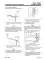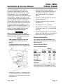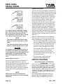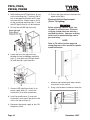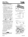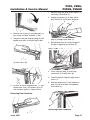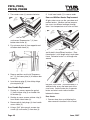
1
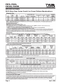
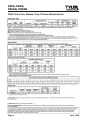
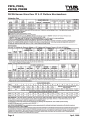
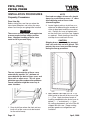
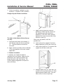
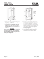
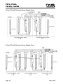
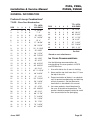
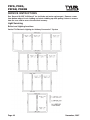
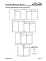
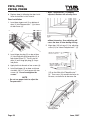
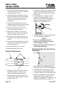
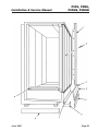
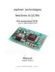
Installation & Service
Manual
P5FG, P5NG, P5FGN and P5NGN
GLASS DOOR PLATFORM MERCHANDISERS
Low Temp & Medium Temp Cases With Reversible Doors
This manual has been designed to be used in conjunction with the
General (UL/NSF) Installation & Service Manual.
Save the Instructions in Both Manuals for Future Reference!!
This merchandiser conforms to the American National Standard Institue & NSF International Health and Sanitation standard ANSI/NSF 7 - 2003.
PRINTED IN Specifications subject to REPLACES
IN U.S.A.
change without notice. EDITION
9/07
ISSUE
DATE
4/08
Tyler Refrigeration * Niles, Michigan 49120
PART
NO.
2000275
REV.
H
P5FG, P5NG,
P5FGN, P5NGN
CONTENTS
Page
Specifications
P5FG, P5NG, P5FGN and P5NGN Specification Sheets . . . . . . . . . 4
Line Sizing Requirements . . . . . . (See General-UL/NSF I&S Manual)
Pre-installation Responsibilities . . . . . (See General-UL/NSF I&S Manual)
Installation Procedures
Carpentry Procedures . . . . . . . . . . . . . . . . . . . . . . . . . . . . . . . . . . 12
Case Line-Up . . . . . . . . . . . . . . . . . . . . . . . . . . . . . . . . . . . . . . . . . 12
Trim Installation/Alignment . . . . . . . . . . . . . . . . . . . . . . . . . . . . . . . . 15
Plumbing Procedures . . . . . . . . (See General-UL/NSF I&S Manual)
Refrigeration Procedures . . . . . . . . . . . . . . . . . . . . . . . . . . . . . . . 16
P5FG/P5FGN Application Requirements . . . . . . . . . . . . . . . . . . . . . 16
Electrical Procedures . . . . . . . . . . . . . . . . . . . . . . . . . . . . . . . . . . . 16
Electrical Considerations . . . . . . . . . . . . . . . . . . . . . . . . . . . . . . . . . 16
ESM/ESS Anti-Sweat Control System . . . . . . . . . . . . . . . . . . . . . . . 16
Defrost Information . . . . . . . . . . . . . . . . . . . . . . . . . . . . . . . . . . . . 17
Defrost Control Charts . . . . . . . . . . . . . . . . . . . . . . . . . . . . . . . . . . 17
Installation Procedure Check Lists (See General-UL/NSF I&S Man.)
Wiring Diagrams . . . . . . . . . . . . . . . . . . . . . . . . . . . . . . . . . . . . . . . . . . . 18
P5FG/P5FGN Domestic & Export (50 Hz) Case Circuits
(Electric Defrost) . . . . . . . . . . . . . . . . . . . . . . . . . . . . . . . . . . . . . . . . 19
(Gas Defrost)
. . . . . . . . . . . . . . . . . . . . . . . . . . . . . . . . . . . . . . . . 24
P5NG/P5NGN Domestic & Export (50 Hz) Case Circuit
(Off Time Defrost) . . . . . . . . . . . . . . . . . . . . . . . . . . . . . . . . . . . . . . . 29
T-8 Prism Lighting Circuits with Anthony Connexxion System . . . 33
Gelcore LED Lighting with Electronic Drivers . . . . . . . . . . . . . . . . . 35
ESM/ESS Anti-Sweat Circuit . . . . . . . . . . . . . . . . . . . . . . . . . . . . . . 37
Cleaning and Sanitation . . . . . . . . . . . . (See General-UL/NSF I&S Manual)
Component Removal and Installation Instructions for Cleaning 38
Shelves with Captive Brackets . . . . . . . . . . . . . . . . . . . . . . . . . . . 38
Bottom Trays . . . . . . . . . . . . . . . . . . . . . . . . . . . . . . . . . . . . . . . . . . 38
Front Air Ducts . . . . . . . . . . . . . . . . . . . . . . . . . . . . . . . . . . . . . . . . 38
Rear Duct Panels . . . . . . . . . . . . . . . . . . . . . . . . . . . . . . . . . . . . . . 38
Discharge Air Honeycomb . . . . . . . . . . . . . . . . . . . . . . . . . . . . . . . 38
NSF Product Thermometer . . . . . . . . . . . . . . . . . . . . . . . . . . . . . . 38
Top Duct . . . . . . . . . . . . . . . . . . . . . . . . . . . . . . . . . . . . . . . . . . . . . 38
Front Cladding/Raceway Cover . . . . . . . . . . . . . . . . . . . . . . . . . . . 38
General Information . . . . . . . . . . . . . . . . . . . . . . . . . . . . . . . . . . . . . . . . 39
Preferred Line-Up Combination . . . . . . . . . . . . . . . . . . . . . . . . . . . 39
Ice Cream Recommendations . . . . . . . . . . . . . . . . . . . . . . . . . . . . 39
Preventive Maintenance . . . . . . (See General-UL/NSF I&S Manual)
Service Instructions . . . . . . . . . . . . . . . . . . . . . . . . . . . . . . . . . . . . . . . . 40
Light Servicing . . . . . . . . . . . . . . . . . . . . . . . . . . . . . . . . . . . . . . . 40
Page 2
June, 2007
Installation & Service Manual
P5FG, P5NG,
P5FGN, P5NGN
Page
Ballast and T-8 Lighting Locations . . . . . . . . . . . . . . . . . . . . . . . . . . 40
Electronic Power Supply and LED Light Fixture Locations . . . . . . 41
T-8 Lamp Replacement . . . . . . . . . . . . . . . . . . . . . . . . . . . . . . . . . 42
LED Light Fixture Replacement . . . . . . . . . . . . . . . . . . . . . . . . . . . . 43
Electronic Ballast Replacement (Prism T-8 Lighting) . . . . . . . . . . 44
Electronic Power Supply Replacement (Gelcor LED Lighting) . . . . 45
Door Servicing . . . . . . . . . . . . . . . . . . . . . . . . . . . . . . . . . . . . . . . 47
Door Removal . . . . . . . . . . . . . . . . . . . . . . . . . . . . . . . . . . . . . . . . 47
Reversing the Door Hardware . . . . . . . . . . . . . . . . . . . . . . . . . . . . 47
Reversing the Frame Hardware . . . . . . . . . . . . . . . . . . . . . . . . . . . 48
Door Handle Replacement . . . . . . . . . . . . . . . . . . . . . . . . . . . . . . 48
Door and Mullion Heater Replacement . . . . . . . . . . . . . . . . . . . . . 49
Door Installation . . . . . . . . . . . . . . . . . . . . . . . . . . . . . . . . . . . . . . . 50
Defrost & Drain Pan Heater Replacement . . . . . . . . . . . . . . . . . . 51
Drain Pan Heater Replacement (P5FG & P5FGN) . . . . . . . . . . . . 51
Electric Defrost Heater Replacement (P5FG & P5FGN) . . . . . . . . 51
Fan Blade and Motor Replacement
(See Gen.-UL/NSF I&S Man.)
Bumper Replacement . . . . . . . . . . . . . . . . . . . . . . . . . . . . . . . . . . 53
Patch End Edge Trim and Overlay Installation . . . . . . . . . . . . . . . . 53
Parts Information . . . . . . . . . . . . . . . . . . . . . . . . . . . . . . . . . . . . . . . . . . . 54
Cladding and Trim Parts List . . . . . . . . . . . . . . . . . . . . . . . . . . . . . . 54
Operational Parts List . . . . . . . . . . . . . . . . . . . . . . . . . . . . . . . . . . . . 56
TYLER Warranty . . . . . . . . . . . . . . . . . (See General-UL/NSF I&S Manual)
The following Frozen Food, Ice Cream and Medium Temperature Glass Door Platform
Merchandiser models are covered in this manual:
MODEL
DESCRIPTION
P5FG2/P5NG2
2-DR, GLASS DOOR PLATFORM MERCHANDISERS (61-5/16”)
P5FG3/P5NG3
3-DR, GLASS DOOR PLATFORM MERCHANDISERS (92”)
P5FG4/P5NG4
4-DR, GLASS DOOR PLATFORM MERCHANDISERS (122-5/8”)
P5FG5/P5NG5
5-DR, GLASS DOOR PLATFORM MERCHANDISERS (153-5/16”)
P5FGN2/P5NGN2
2-DR, NARROW GLASS DOOR PLATFORM MERCHANDISERS
(61-5/16”)
P5FGN3/P5NGN3
3-DR, NARROW GLASS DOOR PLATFORM MERCHANDISERS
(92”)
P5FGN4/P5NGN4
4-DR, NARROW GLASS DOOR PLATFORM MERCHANDISERS
(122-5/8”)
P5FGN5/P5NGN5
5-DR, NARROW GLASS DOOR PLATFORM MERCHANDISERS
(153-5/16”)
November, 2007
Page 3
P5FG, P5NG,
P5FGN, P5NGN
SPECIFICATIONS
P5FG Glass Door Frozen Food & Ice Cream Platform Merchandisers
Page 4
April, 2008
Installation & Service Manual
April, 2008
P5FG, P5NG,
P5FGN, P5NGN
Page 5
P5FG, P5NG,
P5FGN, P5NGN
P5NG Glass Door Medium Temp Platform Merchandisers
Page 6
April, 2008
Installation & Service Manual
April, 2008
P5FG, P5NG,
P5FGN, P5NGN
Page 7
P5FG, P5NG,
P5FGN, P5NGN
P5FGN Narrow Glass Door FF & IC Platform Merchandisers
Page 8
April, 2008
Installation & Service Manual
April, 2008
P5FG, P5NG,
P5FGN, P5NGN
Page 9
P5FG, P5NG,
P5FGN, P5NGN
P5NGN Narrow Glass Door Medium Temp Platform Merchandisers
Page 10
April, 2008
Installation & Service Manual
April, 2008
P5FG, P5NG,
P5FGN, P5NGN
Page 11
P5FG, P5NG,
P5FGN, P5NGN
INSTALLATION PROCEDURES
Carpentry Procedures
Case Line-Up
Before starting the case line-up, review the
store layout floorplans and survey the areas
where case line-ups are going to be installed.
WARNING
These cases are very heavy and require two
or more people to move and/or position
them. Improper handling of these cases
could result in personal injury.
NOTE
Front and rear edges of base rails should
always be used to line-up cases. 6” shims
allow adjoining ends of cases to be
shimmed together.
2. Locate highest point on chalk lines as a
reference for determining the number of
shims to be placed under the case base
rails. Position first case at highest point
on the chalk lines and shim case supports
as required. Check leveling at hand rails
and top of case and back of case.
CAUTION
Shipping braces should only be removed
from case ends that are to be joined. This
protects the cases from possible damage
during the line-up procedure.
NOTE
The rear structure design of these cases
automatically provides a 3” minimum air
space between the back of these cases and
store walls or other cases. This air space
minimizes possible condensation problems.
Forced ventilation might be necessary in
some situations.
1. Snap chalk lines where the front and rear
base rails of the cases are to be located
for the entire line-up.
Page 12
3. Apply double-sided tape and 7/8” x 3/4”
foam gasket to the end of the case at the
(– • –) line. Apply two heavy beads of
caulking compound to the end of case at
dotted (• • •) and dashed (– – –) lines.
All sealing components are in the Filler Kit
shipped with the case. Proper sealing
provides good case refrigeration and
sanitation.
April, 2008
Installation & Service Manual
P5FG, P5NG,
P5FGN, P5NGN
4. If the case requires a plexiglas system
divider or 1” partition, install as follows:
Plexiglas System Divider Installation
NOTE
The holes in the divider will only line-up
one way.
a. Line-up the four holes in the divider (1)
with the four holes for the case pull-ups
(2). Position divider on sealant on
case end.
b. Apply sealant to outside surface of divider
(1) in same position as the case sealant
application.
a. Apply sealant to outside surface of
partition (3) where the two surfaces of
the adjoining case will contact the
partition (3). Drill 3/16” holes through
partition and secure to one of the cases
with four screws (4).
After cases are joined, install the
partition trim:
b. Install vertical trim support (5) on front
edge of partition (3) with four screws (6).
c. Install vertical joint trim (7) to vertical trim
support (5) with four screws (8).
1” Partition Installation
1” partitions are shipped installed as
specified in the case order. Make sure the
partitioned case is being installed in the
proper location in the case line-up. This
assures proper refrigeration to all parts of
the case line-up.
5. Remove bottom trays (9), front duct (10)
and RH or LH rear duct panels (11) from
adjoining ends of both cases. This provides access to the case pull-ups.
January, 2006
Page 13
P5FG, P5NG,
P5FGN, P5NGN
6. Push cases tightly together making sure
the pull-ups are aligned.
7. Add shims (12), as required, under the
adjoining case base rails (13). Check
leveling at top of case (14), and back of
case (15).
CAUTION
Do not drill or use other holes through the
case end for pull-ups. This may deform
the case end and could cause joint leaks
and/or poor refrigeration.
Page 14
8. Position all pull-up bolts and mounting
hardware (16) at pull-up locations A, B,
C, and D. Do not tighten any pull-up
hardware until all of it has been installed.
Tighten all pull-up hardware equally starting at point A and finishing at point D.
Do not overtighten.
9. Install RH or LH rear duct panel (11),
front duct (10), and bottom tray (9).
April, 2008
Installation & Service Manual
P5FG, P5NG,
P5FGN, P5NGN
Trim Installation/Alignment
Horizontal & Vertical Joint Trim Installation
1. Apply bead of caulking compound from
the Filler Kit to the top of each horizontal
joint (1).
NOTE
If additional sealing is preferred, 2” wide
duct tape can be applied to the top of the
internal bottom joint between cases. The
tape will be covered by the horizontal joint
trim. Duct tape is not furnished.
2. Apply sealer to horizontal joint trim (2)
and install joint trim (2) on the top of the
horizontal joint (1).
NOTE
The following information is for joining
cases without 1” partitions. For cases with
1” partition between them, see page 13.
3. Position vertical joint trim (3) in front case
line-up joint (4) and secure with four
screws (5) and screw nuts (6) through
adjoining case door frames (7).
Front Cladding Installation
NOTE
Front cladding is shipped loose. It should
not be installed until all case piping and
electrical hook-ups are out of the way and
secured.
There is a front cladding supplied for each
case. Each front cladding comes with a
bumper preinstalled on it.
1. Position top of front cladding (1) under
bottom lip of the lower door frame
assembly (2).
2. Rotate front cladding (1) down and secure
with screws through holes in the bottom
edge of the front cladding (1).
NOTE
• Kickplate supports are factory installed.
• See “General-UL/NSF I&S Manual” for
kickplate and end closeoff installation
instructions.
April, 2005
Page 15
P5FG, P5NG,
P5FGN, P5NGN
Refrigeration Procedures
NOTE
See “General-UL/NSF I&S Manual” for all
other refrigeration procedure information.
P5FG/P5FGN/ Application Requirements
Temperature Control Strategy
• A suction stop EPR valve is the preferred
method for maintaining temperature
control on parallel compressor system
applications.
• When using a thermostat and liquid line
solenoid for temperature control, the
maximum line-up length that may be
controlled is 10 doors.
• The discharge air temperature shall be
maintained between 1°F to -1°F for frozen
food applications and between -7°F to
-9°F for ice cream applications.
Temperature Sensor Locations
• The sensor used for temperature control
shall be located in the discharge air.
• If a case controller is used, the sensor
used for defrost termination MUST be
insulated and located where the standard
defrost termination klixon is located. If a
case controller is used and the case is
defrosted using electric heaters, the defrost
termination klixon must be replaced with a
70°F fail safe klixon. This meets the safety
requirements.
ed, protected 120V circuit. See “Optional
Electric Defrost” or Optional Gas Defrost”
sections on page 18 of this manual for more
complete fan circuit operation information.
Fluorescent or LED Lamp Circuit
The standard case lighting system is T-8
Electronic Vertical (Prism) lamps. The
standard lighting is 3 to 6 rows of vertical
T-8 lighting located on each side of all doors.
LED case lighting with electronic power
supplies is available as an option.
ATTENTI0N: INSTALLER
• Do not turn on the lights inside the case
unless operating temperature has been
reached. Ballast or power supply failure
may occur when the lights are operating
without refrigeration in the case.
• Do not leave power on to the door and
frame heaters unless operating temperature inside the case has been reached.
Failure to follow this instruction could
cause damage to the door frame.
• The light switch should be left off if
refrigeration is turned off for periods
longer than normal defrosting times.
This prevents possible distortion
and/or damage to non-metal parts
from lighting heat.
NOTE
Lights will remain on during defrost cycle.
Defrost Control Strategy
ESM/ESS Anti-Sweat Control System
• High door openings loads associated with
high food product sales may require two
defrost periods per 24 hour period.
When a line-up of cases are ordered with the
optional ESM/ESS control system, up to 10
cases can be controlled by one master unit
(ESM). The ESM should be mounted on the
top right hand end of one of the cases in the
line-up. By pulling the two required wires
from the ESM to the first slave unit (ESS) in
the line-up, you can daisy chain all the ESS
together at their individual terminal blocks.
The ESS terminal blocks are located in the
lower raceway of each case (see ESM/ ESS
wiring diagram in this manual).
• Pumping down the refrigeration circuit at
the beginning of the defrost period is not
recommended.
Electrical Procedures
Electrical Considerations
Case Fan Circuit
This circuit is to be supplied by an uninterrupt-
Page 16
June, 2007
P5FG, P5NG,
P5FGN, P5NGN
Installation & Service Manual
The TYLER ESM/ESS control system is
designed to effect energy savings in the
operation of P5FG and P5FGN glass door
merchandisers. This is accomplished by
cycling the anti-sweat heat in the door frames
and door glass. Anthony 101 doors use 87
watts of heat (.73 amps) per door that can be
cycled on and off based on the dewpoint.
Anthony Eliminaator doors use 31 watts of
heat (.25 amps) per door that can be cycled
on and off based on the dewpoint. Less
energy is used as the dewpoint lowers. The
ESM draws its very small requirements of 3
watts @ 120 volts (0.03A) from the case.
Installation of the ESM Controller
WARNING
Make sure all power supplies to the
case are disconnected to avoid possible
product damage and/or personal injury.
NOTES
2. Remove ESM cover (5) from ESM
controller (6), then remove knock out (7)
nearest the wiring leads. Install 7/8”
plastic bushing (8) in the knock out
hole (7).
3. Position the ESM controller (6) over the
female receptacle (4).
4. Connect controller plug (9) to female
receptacle (4).
5. Set selector (10) on “C” setting.
6. Secure ESM controller (6) to top of case
(3) with four screws (1). Install the ESM
cover (5).
7. Position metal bracket (11) over the grill
area on the ESM cover (5) and secure to
top of case (3) with two screws (12).
Defrost Information
• ESM dewpoint controller should be
installed by an authorized service
person.
See “General-UL/NSF I&S Manual” for
operational descriptions for each type of
defrost control.
• The ESM controller must only be connected to the case it was shipped with.
Defrost Control Charts
Defrost Option Settings
Defrost
Type
P5FG/P5FGN
Electric (FF)
Electric (IC)
Gas (FF)
Gas (IC)
P5NG/P5NGN
Off Time
Defrost
Defrosts Duration Term.
Per Day
(Min) Temp.
1
1
1
1
46
46
18-20
20-25
60°F
60°F
55°F
55°F
1
34
-----
Most klixons are located on the right end of
the evaporator coil. The diagrams on the
next page show the location for each klixon.
1. Remove four screws (1) and metal cover
(2) from top of case (3). Do not discard
the screws. This will expose the female
receptacle (4).
June, 2007
Page 17
P5FG, P5NG,
P5FGN, P5NGN
Optional Gas Defrost
The area over the drain trough is heated by an
electric drain pan heater. The drain pan is also
heated by two passes of suction line which acts
as a drain pan heater during gas defrosting.
E = Electric Defrost Termination (60/30)
E/D = Electric Defrost Fan Delay (40/20)
G/D = Gas Defrost Fan Delay (25/10)
D = Gas Defrost Drain Pan Heater (70/40)
F/S = Electric Defrost Failsafe (Opt.)
NOTE
• The defrost termination klixon for gas
defrost is located at the bypass check
valve.
• The drain pan heater klixon for electric
defrost is located on the return air grill.
CAUTION
If electronic sensors are used in place of
the klixons, the sensors must be located
in the same location as the klixons for that
defrost type. Any other locations will
effect the refrigeration efficiency of the
case.
Optional Electric Defrost
At case start-up, the fans will not come on
until the fan delay thermostat on the coil
senses 20°F. After the case has been running,
the fan operation is interrupted by the fan
control relay whenever the defrost cycle is
initiated. After defrost, the defrost and drain
heaters will shut off and refrigeration will
resume.
NOTE
The fans will not restart until the coil
temperature reaches 20°F at the fan delay
thermostat.
Page 18
At the initiation of a defrost cycle, a reversing
valve introduces hot gas into the suction line
as normal flow is reversed. When the fan/
heater delay klixon senses 25°F, it turns
off the fans and activates the drain pan heater.
The defrost continues until the coil and drain
pan are completely clear. A gas defrost termination klixon senses the gas leaving the coil.
When termination temperature is reached, a
contact closure signals the rack to close a hot
gas valve and terminate defrosting. (See BUFF
section in Spec Guide.) This valve should be
allowed to cycle, if needed, until fail safe time is
reached.
When fail safe time elapses, the refrigeration
cycle resumes. Case fans will not run until
the coil temperature is brought down to 10°F.
• The fan circuit for Gas Defrost includes the
drain pan heater which is on only when the
fans are off. Since the heater draws more
current than the fans, the entire circuit is
marked to show the highest load rating.
• The fan/heater delay klixon shuts off the
fans at 25°F, and turns the heater on.
• The drain pan heater will shut off if the
drain pan heater klixon exceeds 70°F, but
stays on below 40°F.
• The fan resume running when coil
temperature pulls down to 10°F.
WIRING DIAGRAMS
ELECTRICIAN NOTE - OVERCURRENT
PROTECTION
120V circuits should be protected by 15 or 20 Amp
devices per the requirements noted on the cabinet
nameplate or the National Electrical Code, Canadian
Electrical Code - Part 1, Section 28. 208V defrost
circuits employ No. 12 AWG field wire leads for field
connections. On remote cases intended for end to
end line-ups, bonding for ground may rely upon the
pull-up bolts.
The wiring diagrams on pages 19 thru 32
will cover the most frequently used P5FG,
P5FGN, P5NG and P5NGN case circuits.
June, 2007
P5FG/P5FGN Domestic & Export (50 Hz) Case Circuits
(Electric Defrost)
January, 2006
Page 19
P5FG/P5FGN Domestic & Export (50 Hz) Case Circuits
(Electric Defrost with LED Lighting)
Page 20
July, 2007
P5FG/P5FGN Domestic & Export (50 Hz) Case Circuits
(Electric Defrost for Target)
September, 2007
Page 21
P5FG/P5FGN Domestic & Export (50 Hz) Case Circuits
(Dual Temp Electric Defrost with Front Power Input for Target)
Page 22
April, 2008
P5FG/P5FGN Domestic & Export (50 Hz) Case Circuits
(Dual Temp Electric Defrost with Top Power Input for Target)
April, 2008
Page 23
P5FG/P5FGN Domestic & Export (50 Hz) Case Circuits
(Gas Defrost)
Page 24
June, 2007
P5FG/P5FGN Domestic & Export (50 Hz) Case Circuits
(Gas Defrost with LED Lighting)
July, 2007
Page 25
P5FG/P5FGN Domestic & Export (50 Hz) Case Circuits
(Gas Defrost for Target)
Page 26
September, 2007
P5FG/P5FGN Domestic & Export (50 Hz) Case Circuits
(Dual Temp Gas Defrost with Front Power Input for Target)
September, 2007
Page 27
P5FG/P5FGN Domestic & Export (50 Hz) Case Circuits
(Dual Temp Gas Defrost with Top Power Input for Target)
Page 28
September, 2007
P5NG/P5NGN Domestic & Export (50 Hz) Case Circuits
(Off Time Defrost)
June, 2007
Page 29
P5NG/P5NGN Domestic & Export (50 Hz) Case Circuits
(Off Time Defrost with LED Lighting)
Page 30
July, 2007
P5NG/P5NGN Domestic & Export (50 Hz) Case Circuits
(Off Time Defrost for Target)
September, 2007
Page 31
P5NG/P5NGN Domestic & Export (50 Hz) Case Circuits
(Off Time Defrost with Top Power Input for Target)
Page 32
November, 2007
Installation & Service Manual
P5FG, P5NG,
P5FGN, P5NGN
T-8 Prism Lighting Circuits with Anthony Connexxion™ System
2-Door Electronic Ballast Circuit
3-Door Electronic Ballast Circuit
November, 2007
Page 33
P5FG, P5NG,
P5FGN, P5NGN
4-Door Electronic Ballast Circuit
5-Door Electronic Ballast Circuit
Page 34
June, 2007
Installation & Service Manual
P5FG, P5NG,
P5FGN, P5NGN
Gelcore LED Lighting with Electronic Power Supply Circuits
2-Door LED with Electronic Power Supply Circuit
3-Door LED with Electronic Power Supply Circuit
June, 2007
Page 35
P5FG, P5NG,
P5FGN, P5NGN
4-Door LED with Electronic Power Supply Circuit
5-Door LED with Electronic Power Supply Circuit
Page 36
June, 2007
Installation & Service Manual
P5FG, P5NG,
P5FGN, P5NGN
ESM/ESS Anti-Sweat Circuit
June, 2007
Page 37
P5FG, P5NG,
P5FGN, P5NGN
CLEANING AND SANITATION
Component Removal and
Installation Instructions for
Cleaning
Discharge Air Honeycomb
1. Loosen screws securing rear retainer
plate.
NOTE
Shelves with Captive Brackets
1. Open door and remove product from
shelves.
Note position of the honeycomb grid
during removal so it can be reinstalled
the same way.
2. Lift up and out to remove each shelf/
bracket assembly from slots in rear
uprights. Carefully remove each shelf/
bracket assembly through the door
openings.
2. Slide rear retainer plate back until the
honeycomb grid sections can be removed
from the top duct.
3. After cleaning, replace in reverse order.
Bottom Trays
1. Remove product from bottom of case.
2. Grasp and lift out each of the bottom trays
from the case interior and carefully
remove through the door openings
3. After cleaning, replace in reverse order.
Front Air Ducts
NOTE
Cases with electric defrost have the drain
pan heater klixon located on the front air
duct. Carefully remove klixon before
removing the front air duct to avoid possible damage to the klixon or it’s wiring.
1. Remove lower trays, see this page.
2. Lift out front air duct sections and
carefully remove through door openings.
3. After cleaning, replace in reverse order.
Rear Duct Panels
1. Remove shelf assemblies and bottom
trays, see above.
2. Lift up and pull out to remove rear duct
panels. Carefully remove them through
the door openings.
3. After cleaning, replace in reverse order.
Page 38
CAUTION
Improper installation of the honeycomb
grid section could result in improper air
flow and/or poor refrigeration.
3. After cleaning, replace honeycomb grid
sections as they were removed and
secure with the rear retainer plate
and screws.
NSF Product Thermometer
Remove two screws and product thermometer from left top location in the case. After
cleaning, replace product thermometer and
secure with two screws.
Top Duct
1. Remove shelf assemblies, see above.
2. Remove screws, rear retainer plate and
honeycomb grid sections from top front
of case.
3. Remove screws and top duct from case.
4. After cleaning, replace top duct and
remaining components in reverse order.
Front Cladding
1. Remove screws from bottom of front
cladding and pull down to remove it from
behind the bottom of the door frame
assembly.
2. After cleaning, replace front cladding and
remaining front components in reverse
order.
June, 2007
P5FG, P5NG,
P5FGN, P5NGN
Installation & Service Manual
GENERAL INFORMATION
Preferred Line-up Combinations*
TYLER - Glass Door Merchandiser
DRS
2
3
4
5
TTL. LGTH.
W/O ENDS
5’ 1-5/16”
33
0
1
0
6
84’ 3-7/8”
0
7’ 8”
34
0
0
1
6
86’ 10-1/2”
1
0
10’ 2-5/8”
35
0
0
0
7
89’ 5-3/16”
0
0
1
12’ 9-5/16”
36
0
2
0
6
91’ 11-7/8”
0
2
0
0
15’ 4”
37
0
1
1
6
94’ 6-1/2”
7
0
1
1
0
17’ 10-5/8”
38
0
1
0
7
97’ 1-3/16”
8
0
1
0
1
20’ 5-5/16”
39
0
0
1
7
99’ 7-13/16”
9
0
0
1
1
22’ 11-1516”
40
0
0
0
8
102’ - 2 1/2”
10
0
0
0
2
25’ 6-5/8”
11
0
2
0
1
28’ 1-5/16”
12
0
1
1
1
30’ 7-15/16”
13
0
1
0
2
33’ 2-5/8”
14
0
0
1
2
35’ 9-1/4”
15
0
0
0
3
38’ 3-15/16”
16
0
2
0
2
40’ 10-5/16”
17
0
1
1
2
43’ 5-1/4”
18
0
1
0
3
45’ 11-15/16”
19
0
0
1
3
48’ 6-9/16”
20
0
0
0
4
51’ 1-1/4”
21
0
2
0
3
53’ 7-15/16”
22
0
1
1
3
56’ 2-9/16”
23
0
1
0
4
58’ 9-1/4”
24
0
0
1
4
61’ 3-7/8”
25
0
0
0
5
63’ 10-9/16”
26
0
2
0
4
66’ 5-1/4”
27
0
1
1
4
68’ 11-7/8”
28
0
1
0
5
71’ 6-9/16”
29
0
0
1
5
74’ 1-3/16”
30
0
0
0
6
76’ 7-7/8”
31
0
2
0
5
79’ 2-9/16”
32
0
1
1
5
81’ 9-3/16”
DRS
2
3
4
5
TTL. LGTH.
W/O ENDS
2
1
0
0
0
3
0
1
0
4
0
0
5
0
6
June, 2007
Add 1 1/2”
Per End
*Based on cost effectiveness.
Ice Cream Recommendations
Use the following recommendations for
merchandising ice cream products in P5FG
and P5FGN cases.
1. Use solid shelves for all rows of shelving.
2. Never position top shelf more than 12” from
the top of the case.
3. Proper termination of defrost is an absolute
must to prevent overdefrosting and build up
of frost on product. Set the thermostat
termination as described in this manual.
4. Ice cream products should be placed in
the case at the desired temperature. The
product should be properly rotated to avoid
frost accumulation on the packaging.
Page 39
P5FG, P5NG,
P5FGN, P5NGN
SERVICE INSTRUCTIONS
See “General-UL/NSF I&S Manual” for fan blade and motor replacement. Remove screws
from bottom edge of front cladding and rotate cladding up while pulling it down to remove
from the case and to access the electrical raceway.
Light Servicing
Ballast and Lighting Locations
Vertical T-8 Electronic Lighting for Anthony Connexxion™ System
Page 40
November, 2007
Installation & Service Manual
P5FG, P5NG,
P5FGN, P5NGN
Electronic Power Supply and LED Light Fixture Locations
November, 2007
Page 41
P5FG, P5NG,
P5FGN, P5NGN
T-8 Lamp Replacement
CAUTION
Shut off light switch or disconnect power
supply before changing a lamp. Lighting
system power and/or ballast surges can
burn out adjacent lamps if power is left on.
T-8 Electronic Vertical Lamp (Prism) for
Anthony Connexxion™Systems
NOTE
Center mullion spring clips are secured
to the light cover assembly. End mullion
spring clips are separate parts that
remove completely.
NOTE
Light cover assemblies do not require
disassembly for removal.
2. Starting at top, remove light cover
assembly (3) from light fixture assembly
(2). For center mullion lights, pull light
cover assembly straight out. For end
mulion lights, rotate front of light cover
assembly back until rear side of assembly
can be pulled from light fixture.
NOTE
For Connexxion systems with mylar warning covers on the lamp/socket assemblies,
remove the mylar warning covers from the
lamp/socket assemblies.
1. Using a small flathead screwdriver,
release or remove the three spring steel
clips (1) from both sides of the light fixture
assembly (2).
3. Carefully remove lamp/socket assembly
(4) by pulling from top and bottom
retaining clips (5).
NOTE
• Some Connexxion systems have foam
insulators on the ends of the lamp/
socket assemblies. Move the foam
insulators away from ends of the
lamp/socket assemblies.
• The latest lamp/socket assemblies have
wires that are hard wired into the back
of the lamp/socket assemblies.
• If the lamp/socket wires are connected
to the lamp/socket assemblies with
electrical connectors, disconnect top
and bottom electrical connectors by
depressing locking tab and pulling
away from lamp/socket.
Page 42
November, 2007
Installation & Service Manual
4. Remove both sockets (6) from lamp (7) by
carefully grasping lamp and pulling both
sockets one at a time.
CAUTION
Sockets and foam insulators (when used)
must be properly installed. Improper installation of these components could decrease
lamp efficiency and/or product life.
NOTE
Make sure the text printed on both sockets
is facing the same way.
P5FG, P5NG,
P5FGN, P5NGN
9. Turn on the light switch or reconnect the
power to the lights.
LED Light Fixture Replacement
CAUTION
Shut off light switch or disconnect power
supply before changing a LED light fixture.
Lighting system power and/or power
supply surges can burn out adjacent
LED light fixures if power is left ON.
5. Align holes in bottom of socket (6) with
pins on lamp ends (7). Carefully grasp
new lamp close to one of the ends and
slide on the socket until it is seated
(approx. 1 5/16”) (Fig 13). Repeat for
other end.
7. Position lamp (7) with sockets (6) so
text on sockets faces away from the light
fixture assembly (2) and the socket
marked “Top” is up.
NOTES
• On older Connexxion systems, the wire
connectors need to be snapped into
place on the ends of the sockets.
• Position foam insulators on ends of
ends of sockets (where applicable).
1. To remove low profile cover (1) on top of
the fixture, pull up or twist low profile
cover (1) until tabs release form the slots
in the end cap (2).
2. Remove wire connectors (3) and disconnect LED light fixture lead (4) from power
supply leads (5).
WARNING
Make sure that wires are not routed
between the clips and the sockets.
Improper routing of the wires could result
in product damage and/or personal injury.
Carefully secure the lamp/socket
assembly (4) in the top and bottom
retaining clips (5).
NOTES
• For Connexxion systems with mylar
warning covers on the lamp/socket
assemblies, replace the mylar warning
covers on the lamp/socket assemblies.
• Make sure light cover assembly is
securely assembled before installing.
8. Install light cover assembly (3) in light
fixture assembly (2). Secure by snapping
both sides of three steel spring clips (1)
in light fixture slots or over light fixture lip.
November, 2007
3. Using a flat blade screwdriver, insert the
flat end between the LED light fixture heat
sink (6) and the mounting clip (7).
Page 43
P5FG, P5NG,
P5FGN, P5NGN
4. While holding the LED light fixture (8), pry
out the mounting clip (7) and twist the fixture in the opposite direction until it pops
free from the clip. Repeat steps 3 and 4
on the remaining mounting clips (7) until
the LED light fixture (8) can be removed.
12. Turn on the light switch or reconnect the
power to the lights.
5. Discard the old LED light fixture (8).
Before replacing a ballast, make sure
all power is off to the case. Electrical
servicing should always be done by a
qualified electrician. Improper servicing
could result in product damage and/or
personal injury.
Electronic Ballast Replacement
(Prism T-8 Lighting)
WARNING
NOTE
Refer to T-8 ballast location page and
wiring diagrams in this manual for specific
model information.
6. Center the new LED light fixture (8)
between the top and bottom mounting
clips (7), then push the LED light fixture
(8) until the clips snap into place.
1. Remove door following the door removal
instructions in this manual.
7. Connect LED light fixture leads (4) to
power supply leads (5). Install wire
connectors (3) on wire connections.
2. Using a flat-headed screwdriver under the
8. Install low profile cover (1) over wire
connections and snap it into place in the
slots in the top end cap (2).
9. Reconnect the power supply or turn ON
the power switch.
Page 44
November, 2007
Installation & Service Manual
back edge of the contact plate retainer (1),
gently pull up to unsnap both sides of
retainer (1) from mullion (2).
3. Remove contact plate (3) and heat barrier
(4) from mullion (2).
4. Remove screw (5) on top end of ballast (6).
Slide ballast (6) up and out of punched
tabs (7) in mullion (2).
5. Disconnect all wire leads (8) at connectors
to ballast (6).
6. Insert bottom of new ballast (6) in bottom
tabs (7) on mullion (2) and secure with
screw (5) in top end of ballast (6).
7. Reconnect wire leads (8) at connectors to
new ballast (6) following the wiring diagram
on the new ballast (6).
P5FG, P5NG,
P5FGN, P5NGN
Electronic Power Supply Replacement
(LED Light Fixtures)
WARNING
Before replacing a power supply, make
sure all power is off to the case. Electrical
servicing should always be done by a
qualified electrician. Improper servicing
could result in product damage and/or
personal injury.
NOTE
Refer to Electronic Power Supply and LED
Light Fixture Location page and wiring diagrams in this manual for specific model
information.
1. Remove door following the door removal
instructions in this manual.
8. Position heat barrier (4) in the mullion (3).
9. Position contact plate (3) flat on the mullion
(2). While holding contact plate (3), insert
retainer (1) into front edge of mullion (3),
then snap retainer (1) into back edge of
mullion (3). Repeat process to install
retainer (1) on opposite side.
2. Using a flat-headed screwdriver under the
back edge of the contact plate retainer
(1), gently pull up to unsnap both sides of
retainer (1) from mullion (2).
3. Remove contact plate (3) and heat barrier
(4) from mullion (2).
November, 2007
Page 45
P5FG, P5NG,
P5FGN, P5NGN
4. Remove screw (5) on top end of LED
power supply (6). Slide LED power
supply (6) up and out of punched tabs (7)
in mullion (2).
5. Disconnect all wire leads (8) at connectors to LED power supply (6).
6. Insert bottom of new LED power supply
(6) in bottom tabs (7) on mullion (2) and
secure with screw (5) in top end of LED
power supply (6).
7. Using the appropriate schematics on
pages 34 and 35, connect the LED power
supply outlet leads to the previous LED
light fixture leads using wire connectors
approved for low temperature usage.
8. The remaining gray and purple wires from
the output side of the LED power supply
(6) are used to control the optional dimming feature. These wires need to be
connected to the case controller or must
be indiviually capped off if not used.
10. Replace door following the door installation instructions in this manual.
11. Reconnect power to the case.
9. Set dip switches (9) on LED power supply
(6) for the appropriate usage as shown on
page 34 and 35 in this manual.
10. Position heat barrier (4) in the mullion (3).
11. Position contact plate (3) flat on the mullion (2). While holding contact plate (3),
insert retainer (1) into front edge of mullion (3), then snap retainer (1) into back
edge of mullion (3). Repeat process to
install retainer (1) on opposite side.
12. Replace door following the door installation instructions in this manual.
13. Reconnect power to the case.
1. Release tension on Torquemaster™ (1) by
turning screw (2) clockwise.
Door Servicing
Door Removal
CAUTION
Before removing door, decrease torque
tension clockwise to prevent possible
damage to the door.
Page 46
2. Open door (3) and lock into the
hold-open position.
June, 2007
Installation & Service Manual
P5FG, P5NG,
P5FGN, P5NGN
1. Remove hinge pin plug access covers (1)
from both side of door (2).
2. Unplug connectors (3) to door and/or
glass heater (4) and remove hinge pin
3. Remove two screws (6) and hold-open (4)
from frame and door standoffs (7 & 8).
4. Compress and pull hinge pin plug (9) with
needle nose pliers to release top of door
plug (5) through top of door (2).
3. Reroute lead wires (6) to new hinge pin
location in opposite end of door (2).
(3) from frame (10).
4. Install hinge pin plug (5) and attach
connectors (3) to lead wires (6).
5. Carefully replace hinge pin plug access
covers (1).
5. Lift door (3) out of Torquemaster™ (1) and
remove from case. Place door (3) on its
side and lean against a stable surface.
6. Slide out torque rod (7) from bottom of
door (2) and insert back into opposite
end of door (2).
Reversing Door Hardware
Reversing Frame Hardware
June, 2007
Page 47
P5FG, P5NG,
P5FGN, P5NGN
1. Turn center screw (1) counter-clockwise
5. Install new handle (7) in reverse order.
Door and Mullion Heater Replacement
All glass door cases use the same door and
mullion heaters. Medium and low temperature cases run different wattages through
them. Low temperature cases also use elec-
and remove Torquemaster™ (2) from
bottom door frame (3).
2. Pry out cover plate (4) from opposite end
of bottom door frame (3).
trically heated door glass. Mullion heaters
are located in four different locations. Door
frame heater is a full length wire in each door
frame. Perimeter heater is a full length wire
around
3. Reverse positions and install Torquemaster™ (2) and cover plate (4) in bottom door
frame (3).
4. Insert dummy plug (5) into old top hinge
pin receptacle (6).
Door Handle Replacement
1. Starting at a corner, remove the gasket
(1) from retainer strip (2) on handle side
of the door (3).
2. Starting at corner, remove retainer strip (2)
from handle side of door (3).
3. Remove plastic hole plugs (4) from handle
access holes (5).
the entire case frame. Threshold heater is a
additional wire across the lower part of the
case frame. Vertical heater has a separate
heater and wire in each vertical mullion
between the doors.
Door Heater
1. Remove door from case following the
door removal instruction in this manual.
4. Using a 5/32” allen wrench, remove two
screws (6) and handle (7) from door (2).
Page 48
June, 2007
Installation & Service Manual
2. Starting at corner, remove gasket (1) from
retainer strip (2).
P5FG, P5NG,
P5FGN, P5NGN
adjacent top contact plates. Threshold
3. Starting at a corner, remove all retainer
wire requires removal of bottom and end
contact plates. Perimeter wire requires
strips (2) from the door (3).
4. Disconnect or cut solid heater lead wire
(4) and remove from door (3). Insert
and connect new solid lead wire (4) in
door (3).
5. Replace retainer strips (2) and gasket (1)
on the door (3).
6. Replace door on case following the door
installation instructions in this manual.
removal of all contact plate (top, bottom,
end, and center).
3. Disconnect or cut defective heater wire (5)
and remove from mullion (4).
Mullion Heater
1. Remove necessary door(s) following the
door removal instructions in this manual.
2. Using a screwdriver, remove necessary
contact plate retainers (1) and contact
plates (2) and heat barriers (3), where
applicable, from mullions (4) to expose
heater wire(s). Vertical wire requires
removal of vertical contact plate and two
June, 2007
4. Connect and install new heater wire (5) in
mullion (4).
5. Replace heat barriers (3), where applicable, and contact plates (2) and contactplate retainers (1) on mullions (4)
Page 49
P5FG, P5NG,
P5FGN, P5NGN
6. Replace door(s) following the door installation instructions in this manual.
• When Torquemaster™ is properly
adjusted, the door will securely close
Door Installation
1. Insert door torque rod (1) on bottom of
door (2) into Torquemaster™ (3) at base
of door frame (4).
without slamming. Over adjusting will
cause the door to slam during closing.
5. Align door (10) in frame (11) by adjusting
screw (12) on side of Torquemaster™ (3).
2. Insert hinge pin plug (5) on top of door
(2) into hinge pin plug receptacle (6) at
top of door frame (7). Push in top of
door (2) until hinge pin plug (5) snaps
into place.
5
3. Apply loctite to threads of two screws (8).
4. Install hold-open (9) on door and frame
standoffs (10 & 11) and secure with two
screws (8). Do not overtighten the
screws.
NOTE
4
6
R
A
C
E
W
A
Y
6. Adjust closing force by turning the screw
(13) on the front of the Torquemaster™
(3). Turn screw (13) counter-clockwise to
increase, or clockwise to decrease the
• Do not use power tools to adjust the
Torquemaster™.
closing force.
Page 50
June, 2007
Installation & Service Manual
P5FG, P5NG,
P5FGN, P5NGN
5. Install new heater (4) and secure with
clips (8) and screws (7) in bottom of the
case (3).
6. Connect the heater wire (4) at the
connectors (5 & 6), one in the raceway
and one in the bottom right-hand side
of the case (3).
7. Install bottom trays (2) in case (3).
8. Install raceway cover (1) following
raceway cover installation instructions
in this manual.
9. Reconnect power to the case.
Electric Defrost Heater Replacement
(P5FG & P5FGN)
3. Remove mounting screws and top coil
closeoff (6) from coil assembly (5).
NOTE:
Defrost heater wire run completely around
the coil assembly with the connector lead
on the right side of the coil. Note routing
of wires before removing the defrost
heater, so new heater can be installed the
same way.
1. Remove bottom trays (1) from case (2).
4. Remove heater retainer clips (7) from
slots in rear of coil assembly (5).
4
3
2. Disconnect the defective defrost heater
(3) at the connector (4) on the right-hand
side of the coil assembly (5).
5. Remove mounting screws and carefully
lift and place fan panel (8) on top of coil
assembly (5).
6. Remove heater retainer clips (7) from
slots in front of coil assembly (5).
June, 2007
Page 51
P5FG, P5NG,
P5FGN, P5NGN
7. Lift and remove defective heater (3) from
slots in front and rear of coil assembly (5)
and remove from case (2).
8. Carefully position new defrost heater (3)
over the fan panel (8) and coil assembly
(5) and insert the heater wire (3) in the
slots in the front and rear of the coil
assembly (5).
9. Secure the new heater wire (3) in the
|bottom of the front slots of coil assembly
(5) with the heater retainer clips (7).
3. If bumper end cap (3) is damaged, remove
screws and slid off bumper end cap (3).
Replace with new end cap (3) and secure
with screws.
4. Use old bumper as a guide to cut new
bumper to the proper length. If old
bumper is not available, cut bumper 1/4”
longer than the measured distance
between the installed end cap.
10. Carefully reposition fan panel (8) and
secure with mounting screws.
11. Secure the new heater wire (3) in the
bottom of the rear slots of coil assembly
(5) with the heater retainer clips (7).
12. Install top coil closeoff (6) on top of coil
assembly (5) and secure with mounting
screws.
13. Connect the new defrost heater (3) at the
connector (4) on the right-hand side of
the coil assembly (5).
14. Install bottom trays (1) in case (2).
15. Reconnect power to the case.
Bumper Replacement
5. Starting at one end, snap the new bumper
(1) onto the bumper retainer (2).
NOTE
• The use of a wooden block and a
hammer may be helpful to snap hard
to install bumpers in place.
• Bumpers will shrink when the cases are
at operating temperature.
Patch End Edge Trim and Overlay
Installation
1. Remove loose or damaged edge trim (1)
from patch end (2). Discard old edge trim.
1. Starting at one of the end joints, pry one
end of the bumper (1) until it start to
release from the bumper retainer (2).
2. Grasp the loose end of the bumper (1)
and pull firmly to peel bumper (1) off the
bumper retainer (2).
Page 52
2. If installing patch end overlay, position
overlay on outer surface of patch end (2)
and secure with screws in pre-drilled holes.
3. Position new edge trim (1) over exposed
edge of patch end (2) and/or overlay.
Secure the new edge trim (1) with screw (3)
through pre-drilled holes in edge trim.
June, 2007
P5FG, P5NG,
P5FGN, P5NGN
Installation & Service Manual
Defrost & Drain Pan Heater Replacement
WARNING
Before replacing defrost or drain pan heater, shut off electrical power to the case to avoid
personal injury and/or death.
Drain Pan Heater Replacement
(P5FG & P5FGN)
1. Remove screws from bottom edge of front cladding (1). Rotate bottom edge up and pull
front cladding (1) down to remove it from the case (3).
2. Remove bottom trays (2) from case (3).
3. Disconnect the defective drain pan heater (4) at the connectors (5 & 6), one in the raceway
and one in the bottom right-hand side of the case (3).
4. Remove screws (7), clips (8) and drain pan heater (4) from bottom of case (3).
PARTS INFORMATION
Operational Parts List
Desc. (Domestic & Export)
Fan Motors (domestic)
(115 V/ 1 PH/ 50-60 HZ)
Fan Motors (export)
(230 V/ 1 PH/ 50-60 HZ)
Fan Blades (8.75” 30° 5B)
Fan Motor Brackets
Fan Bracket Plate
Opt. ECM Fan Motors
(115 V/ 1 PH/ 50-60 HZ)
Opt. ECM Fan Blades (8.75” 20° 5B)
Opt. ECM Fan Motor Brackets
T8 Vert. Ballast (1 lamp)
2DR
5243498
9 Watt
9458943
9 Watt
5187551
5235087
9041077
9025000
12 Watt
5231809
5205112
5875110
3DR
5243498
9 Watt
9458943
9 Watt
5187551
5235087
9041077
9025000
12 Watt
5231809
5205112
4DR
5243498
9 Watt
9458943
9 Watt
5187551
5235087
9041077
9025000
12 Watt
5231809
5205112
5875110
5DR
5243498
9 Watt
9458943
9 Watt
5187551
5235087
9041077
9025000
12 Watt
5231809
5205112
T8 Vert. Ballast (2 lamp)
Opt. LED Power Supply
5875111
5875000
5875111**
5875000
5875111**
5875000
5875111†
5875000
(GE Part No.)
T8 Vert. Flrscnt. Lamp F040/841
Opt. LED Light Fixture, LH End
(GE Part No.)
Opt. LED Light Fixture, RH End
(GE Part No.)
Opt. LED Light Fixture, CTR
(GE Part No.)
Electric Defrost Heater
(P5FG/P5FGN)
Elec. or Hot Gas Drain Pan Heater
(Domestic)(P5FG/P5FGN)
Opt. Elec. or Hot Gas Drain Pan
June, 2007
(60-16189-0001) (60-16189-0001) (60-16189-0001) (60-16189-0001)
5093932
5875001
5093932
5875001
5093932
5875001
5093932
5875001
(60-16194-0001) (60-16194-0001) (60-16194-0001) (60-16194-0001)
5875002
5875002
5875002
5875002
(60-16193-0001) (60-16193-0001) (60-16193-0001) (60-16193-0001)
5875003
5875003
5875003
5875003
(60-16195-0001) (60-16195-0001) (60-16195-0001) (60-16195-0001)
2003435
2003436
2003437
2003438
1200W/208V 1975W/208V 2725W/208V 3500W/208V
2008013
2008014
2008015
2008016
137W/120V 226W/120V 311W/120V 400W/120V
2008017
2008018
2008019
2008020
Page 53
P5FG, P5NG,
P5FGN, P5NGN
Cladding and Trim Parts List
Item Description
1
2DR
3DR
4DR
5DR
2000347
2000347
2000347
2000347
(Black Anod. Aluminum)
2000348
2000348
2000348
2000348
(Anodized Aluminum)
2000349
2000349
2000349
2000349
5076411 (6)
5076411 (6)
5076411 (6)
5076411 (6)
2000110
2000111
2000112
2000113
5183536 (3)
5183536 (4)
5183536 (6)
5183536 (6)
Door Joint Trim
(Satin Aluminum)
2
Binding Screw
3
Front Cladding, Ptd.
Screw
4
Bumper, 3”
Bumper Retainer, Blk.
Bumper End Cap
5
2000263
color per order
2000264
--------------------
--------------------
2000265
color per order
2000266
--------------------
Metal Kickplate, Ptd.
2000197
2000196
2000195
2000194
Kickplate Joint Trim, Ptd.
2000209
2000209
2000209
2000209
5183536 (9)
5183536 (12)
2000240
2000240
2000240
2000240
9025833 (6)
9025833 (8)
9025833 (8)
9025833 (8)
Screw
6
--------------------
Kickplate Support Assy.
Shoulder Screw
5183536 (15) 5183536 (18)
7
Raceway Assembly
2000117
2000118
2000119
2000120
8
LH or RH End Close-off, Ptd.
(P5FG/P5NG)
2000400
2000400
2000400
2000400
9
(P5FGN/N5NGN)
2000401
2000401
2000401
2000401
End Close-off Bracket
2000402
2000402
2000402
2000402
2000207
2000207
2000207
2000207
2000206
2000206
2000206
2000206
Horizontal Joint Trim
(P5FG/N5NG)
(P5FGN/P5NGN)
Page 54
June, 2007
Installation & Service Manual
June, 2007
P5FG, P5NG,
P5FGN, P5NGN
Page 55