1
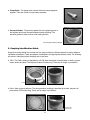
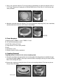
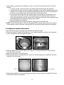
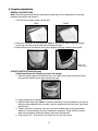
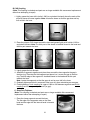
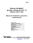
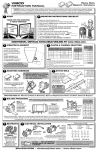
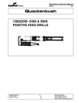
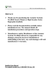
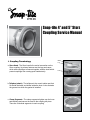
Snap-tite 4” and 5” Storz
Coupling Service Manual
1. Coupling Terminology
a. Storz Head - The Storz head is the swivel connection on the Storz coupling. Its primary features are the lugs and ramps which allow couplings to connect together, and the locks which prevent couplings from coming apart inadvertently.
b. Tailpiece (shank) - The tailpiece is the round, tubular part that fits inside the head, and slides inside the hose. It also contains the groove into which the gasket is installed.
c. Clamp Segments - The clamp segments tighten over the hose and tailpiece and secure the hose to the coupling tail piece. There are 3 identical segments in each coupling.
Ramp
Lug
Lock
d. Clamp Bolts - The clamp bolts connect the three clamp segments together. There are 3 bolts in each clamp assembly.
e. Pressure Gasket - The pressure gasket fits in the gasket groove in the tailpiece and forms the seal between mating couplings. The
pressure gasket is black and has a flat mating surface.
Pressure gasket installed in tailpiece
2. Coupling Identification Guide
Snap-tite coupling design has evolved over the years resulting in different styles that require different
installation procedures. These procedures are detailed in the appropriate sections below. The following
will assist in identifying which couplings are on the hose.
a.
CAS - The CAS coupling is identified by a 2-3/8” wide clamp and a colored (blue or black), polymer sleeve under the clamp. The tailpiece is about 5 inches long. These are no longer in production.
2-3/8”
b. Short, black, polymer tailpiece. The next generation coupling is identified by a black, polymer tail
piece about 3-3/8 inches long. These are no longer in production.
5 inch: 3-3/8”
4 inch: 3-1/8”
2
c. Short, cast, aluminum tailpiece. The current design is identified by an aluminum tailpiece which is 3-1/2” long. These were in production in 2008 and 2009 for the 5 inch Storz. A 4 inch version was never produced.
5 inch: 3-1/2”
d. Machined, extruded aluminum tailpiece. The current generation (beginning 2010), has a machined, anodized aluminum tail piece, and a unique clamp design.
5 inch: 3-3/8”
4 inch: 3-1/8”
3. Tools Required
A.Mounting plate (FMB40 = 4 inch; FMB50 = 5 inch)
B.1/2” drive ratchet/socket wrench
C.5/16” Allen socket (1/2” drive)
D.Torque wrench 1/2” drive (foot pounds)
E.Knife
F. Screwdriver or Awl
G. Grease (Lubriko L-206 or equivalent)
4. Coupling Removal
Coupling removal is similar for the various coupling styles.
a. Secure the coupling in the appropriate size mounting plate. Mounting plates are available through your Snap-tite dealer. (Note: A vise may be used to hold the coupling by the lugs, but care must be taken not to damage the lugs.)
b. Remove the coupling by cutting the hose off close to the coupling tailpiece. The hose may be cut
using a sharp utility knife.
Mounting Plate
3
c. If the coupling, or any part of the coupling, is to be re-used, the hose will need to be cut off of the tailpiece.
i. In order to do this, remove the bolts in the clamp segments and remove the segments.
ii. If possible pull the hose end off the tailpiece. Generally, the hose will be tightly adhered to the tail piece. If so, carefully cut the hose end longitudinally and peel the hose off of the tailpiece. Be careful not to heavily scratch the tailpiece as this could cause a leak.
iii.To remove the Storz head, the snap-ring will need to be removed. Use a screwdriver or an awl to pop the ring out of its groove, and then slide it off of the tailpiece. (Note: The short, black, poly tailpiece does not use a snap-ring. The tailpiece will pop out of the head by turning the coupling lug-side up and pressing down on the head.)
iv.Slide the head off of the tailpiece.
v. Clean any parts that are to be re-used with soapy water and a scrub brush.
d. NOTE: The Storz head used on CAS style couplings (with the polymer sleeve) may not fit properly on the tailpieces used on the other coupling styles. We recommend replacing the entire assembly.
5. Coupling Assembly Instructions
These instructions apply to couplings with aluminum tails and snap-rings.
a. Ensure the gasket is installed in the tailpiece. If not, install the gasket by ‘rocking’ it into the gasket groove. Soapy water may be used as lubrication.
b. Slide the tailpiece into the Storz head from the lug end. If re-using components, ensure they are clean and free of corrosion.
c. Secure the assembly in a mounting plate.
d. Slide the snap-ring over the tailpiece until it snaps into the snap-ring groove located just above the shoulder in the Storz head.
Snap-ring
Snap-ring groove
e. Remove the assembly from the mounting plate and check for free operation of the head. The head should swivel easily on the tailpiece.
4
6. Coupling Installation
GENERAL INSTRUCTIONS
Note: The following assumes that the replacement couplings are fully assembled. For coupling
assembly instructions see Section 5.
i. Trim the hose to obtain a clean, square end.
“Bad”
“Good”
ii. Secure the coupling in a mounting plate. (Note: A vise may be used to hold the coupling
by the lugs, but care must be taken not to damage the lugs.)
iii.Slide the hose over the tailpiece until it stops against the ledge inside the Storz head.
Ledge inside
the Storz head
SPECIFIC INSTRUCTIONS (All types)
A.Machined Aluminum Coupling (current 2010 design):
1. Place the clamp segments around the hose. The square corner goes towards the Storz head and the rounded corner goes towards the hose.
2. Lightly grease the bolt threads.
3. Install the bolts finger-tight. (Note: For ease of assembly it may be possible to pre-connect
the three clamp segments with two bolts, wrap the segments around the hose, then install the third bolt.)
4. Tighten each bolt in sequence a few turns at a time maintaining an even gap between
segments. Avoid pinching of the hose between the segments. A light solution of soapy
water can be used as a lubricant between the hose and segments.
5. Final torque is 25 – 30 ft-lbs for 4 inch and 5 inch. Do not over-torque.
5
B.CAS Coupling
(Note: This coupling is obsolete and parts are no longer available. We recommend replacement rather than attempting to repair).
1.Lightly grease the hose with Lubriko L-206 (or equivalent lubricant) where the ends of the
polymer sleeve will come together. Note: Locate the sleeve so that the gap does not lay
over a fold in the hose.
Lightly grease
2. Place the polymer CAS sleeve around the hose and grease lightly with Lubriko L-260 or equivalent lubricant. Note: The thick part of the sleeve is installed closest to the head and
the thin part towards the hose.
3. Lightly grease the bolt threads.
4. Assemble 2 segments together and place them around the hose opposite the gap in
the blue ring. Then take the third segment and place it so it covers the gap in the blue
ring. The thick edge of the segment is installed closest to the head and the thin part towards the hose.
Note: Locate the segments so that the gaps do not lay on a fold in the hose.
5. Gradually tighten each bolt in sequence a few turns at a time maintaining an even gap.
6. Finish tightening 5 inch couplings to a gap of .060 to .090 between segments and 4 inch
couplings until the segments just touch (no gap).
C.Short Poly Tailpiece:
(Note: This coupling is obsolete and parts are no longer available. We recommend
replacement rather than attempting to repair).
1. Place the clamp segments around the hose.
The flat edge of the segments rests on the Storz
head and the edge with the internal bevel is towards
the hose.
6
2. Lightly grease the bolt threads.
3. Install the bolts finger-tight. (Note: For ease of assembly it may be possible to pre-connect
the three clamp segments with two bolts, wrap the segments around the hose, then install the third bolt.)
4. Tighten each bolt in sequence a few turns at a time maintaining an even gap between
segments. Avoid pinching of the hose between the segments. A light solution of soapy
water can be used as a lubricant between the hose and segments.
5. Final torque is 25 – 30 ft-lbs for 4 inch and 5 inch. Do not over-torque.
D.Short Aluminum Tailpiece:
(Note: This coupling is obsolete and parts are no longer available. We recommend replace-
ment rather than attempting to repair).
1. Place the clamp segments around the hose. The flat edge of the segments rests on the Storzhead and the edge with the internal bevel is towards the hose.
2. Lightly grease the bolt threads.
3. Install the bolts finger-tight. (Note: For ease of assembly it is possible to pre-connect the
three clamp segments with two bolts, wrap the segments around the hose, and then install
the third bolt.)
4. Tighten each bolt in sequence a few turns at a time maintaining an even gap between
segments. Avoid pinching of the hose between the segments. A light solution of soapy
water can be used as a lubricant between the hose and segments.
5. Final torque is 25 – 30 ft-lbs for 4 inch and 5 inch. Do not over-torque.
7
7. Service Testing
WARNING: In accordance with NFPA 1962, par. 7.2.11, all hose is to be service tested after couplings are serviced and/or replaced. Failure to do so can result in serious injury to personnel or
damage to equipment.
WARNING: NFPA 1962, par. 6.2.12 requires that the bolts on Storz type couplings be re-torque
at least annually to the manufacturer’s specified settings, and that any components that show
signs of wear be replaced.
Consult NFPA 1962 for instructions on how to perform service testing. Service testing of hose
can be dangerous if done improperly. If Fire Department personnel are not trained in how to perform service testing Snap-tite Hose recommends hiring a hose testing service to perform annual
and repair service tests.
A copy of NFPA 1962 can be purchased from NFPA at the following: http://www.nfpa.org/
8. Maintenance Instructions
Storz couplings are simple, reliable devices that will operate safely and satisfactorily for many years with
basic care and maintenance. NFPA 1962, section 6.2 contains excellent information regarding coupling
care and maintenance. Following is additional information based on NFPA 1962 and direct experience.
a.
Lubrication: Lubricating Storz couplings is not recommended because of the possibility of pick- ing up dirt and other contamination that can interfere with proper operation. A Storz coupling in good condition will connect properly without lubrication of any kind. Lubricating the gasket faces has minimal benefit since the gaskets do not slide against each other when couplings are connected.
b. Cleaning: The couplings can be cleaned by simply spraying with water. The areas of concern are the lugs, ramps, locks, and the swivel. Ensure the lugs and ramps are free of dirt and debris. Check that the lock operates freely. Ensure that the swivel moves freely.
c.
Gasket replacement: The Storz gaskets are very durable and rarely need replaced. Should replacement be necessary, the old gasket can be pried out with a small screwdriver or awl, taking care not to damage the groove in the tailpiece. The new gasket is installed by ‘rocking’ it into the groove. Soapy water can be used as lubrication.
d. Lock: The lock is a critical safety feature which prevents accidental separation of the couplings.
It must operate freely and must securely lock the mating couplings together. Replace any parts which are damaged. A lock repair kit, part number STZLK, is available from your dealer.
e. Swivels: The Storz head is designed to swivel easily on the tailpiece. Any coupling that does
not swivel must be cleaned or repaired. Possible causes of not swiveling are: contamination;
corrosion; broken or displaced snap-ring; damaged tailpiece or Storz head.
WARRANTY AND DISCLAIMER: There are no express warranties that extend beyond the description
on the face hereof. SELLER DISCLAIMS ANY IMPLIED WARRANTIES OF MERCHANTABILITY OR
OF FITNESS FOR ANY PARTICULAR PURPOSE. Since seller cannot control the manner or use of
its products after their sale, Seller will not be responsible for any consequential or indirect damages.
Rather, Seller will, at its option, either replace the products sold or refund the purchase price. No
warranties will apply if the products are in any way altered, modified, or damaged after delivery by
the Seller.
217 Titusville Road
Union City, Pennsylvania 16438-8698 USA
Ph: 814-438-7616 Fax: 814-438-8163
e-mail: [email protected]
ISO-9001 Certified
03-1180ME-0410
8